Falmec Groupe aspirant ou filtrant Falmec GRUPPO INCASSO - notice
Falmec Groupe aspirant ou filtrant Falmec GRUPPO INCASSO - notice
Falmec Groupe aspirant ou filtrant Falmec GRUPPO INCASSO - notice
You also want an ePaper? Increase the reach of your titles
YUMPU automatically turns print PDFs into web optimized ePapers that Google loves.
N<br />
MOUNTING INSTRUCTIONS, RANGE HOODS<br />
WITH BOX<br />
<strong>GRUPPO</strong> <strong>INCASSO</strong><br />
Step 1<br />
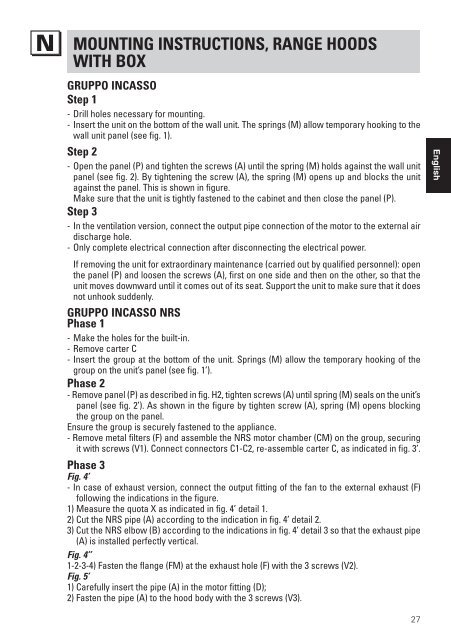
- Drill holes necessary for m<strong>ou</strong>nting.<br />
- Insert the unit on the bottom of the wall unit. The springs (M) allow temporary hooking to the<br />
wall unit panel (see fig. 1).<br />
Step 2<br />
- Open the panel (P) and tighten the screws (A) until the spring (M) holds against the wall unit<br />
panel (see fig. 2). By tightening the screw (A), the spring (M) opens up and blocks the unit<br />
against the panel. This is shown in figure.<br />
Make sure that the unit is tightly fastened to the cabinet and then close the panel (P).<br />
Step 3<br />
- In the ventilation version, connect the <strong>ou</strong>tput pipe connection of the motor to the external air<br />
discharge hole.<br />
- Only complete electrical connection after disconnecting the electrical power.<br />
If removing the unit for extraordinary maintenance (carried <strong>ou</strong>t by qualified personnel): open<br />
the panel (P) and loosen the screws (A), first on one side and then on the other, so that the<br />
unit moves downward until it comes <strong>ou</strong>t of its seat. Support the unit to make sure that it does<br />
not unhook suddenly.<br />
<strong>GRUPPO</strong> <strong>INCASSO</strong> NRS<br />
Phase 1<br />
- Make the holes for the built-in.<br />
- Remove carter C<br />
- Insert the gr<strong>ou</strong>p at the bottom of the unit. Springs (M) allow the temporary hooking of the<br />
gr<strong>ou</strong>p on the unit’s panel (see fig. 1’).<br />
Phase 2<br />
- Remove panel (P) as described in fig. H2, tighten screws (A) until spring (M) seals on the unit’s<br />
panel (see fig. 2’). As shown in the figure by tighten screw (A), spring (M) opens blocking<br />
the gr<strong>ou</strong>p on the panel.<br />
Ensure the gr<strong>ou</strong>p is securely fastened to the appliance.<br />
- Remove metal filters (F) and assemble the NRS motor chamber (CM) on the gr<strong>ou</strong>p, securing<br />
it with screws (V1). Connect connectors C1-C2, re-assemble carter C, as indicated in fig. 3’.<br />
Phase 3<br />
Fig. 4’<br />
- In case of exhaust version, connect the <strong>ou</strong>tput fitting of the fan to the external exhaust (F)<br />
following the indications in the figure.<br />
1) Measure the quota X as indicated in fig. 4’ detail 1.<br />
2) Cut the NRS pipe (A) according to the indication in fig. 4’ detail 2.<br />
3) Cut the NRS elbow (B) according to the indications in fig. 4’ detail 3 so that the exhaust pipe<br />
(A) is installed perfectly vertical.<br />
Fig. 4’’<br />
1-2-3-4) Fasten the flange (FM) at the exhaust hole (F) with the 3 screws (V2).<br />
Fig. 5’<br />
1) Carefully insert the pipe (A) in the motor fitting (D);<br />
2) Fasten the pipe (A) to the hood body with the 3 screws (V3).<br />
English<br />
27


