9362079a, Offset-Parabolantenne fuer ein, zwei oder drei ... - Kathrein
9362079a, Offset-Parabolantenne fuer ein, zwei oder drei ... - Kathrein
9362079a, Offset-Parabolantenne fuer ein, zwei oder drei ... - Kathrein
- TAGS
- fuer
- kathrein
- www.kathrein.de

You also want an ePaper? Increase the reach of your titles
YUMPU automatically turns print PDFs into web optimized ePapers that Google loves.
1. Verwendungszweck<br />
Die <strong>Parabolantenne</strong> CAS 120 ist vorgesehen:<br />
– Ausschließlich für den Empfang von Satellitensignalen<br />
und<br />
– nur für den Einsatz als Haushaltsantenne.<br />
Als Haushaltsantenne gilt gemäß DIN 4131 <strong>ein</strong>e<br />
Antenne mit höchstens 6 m freier Mastlänge und <strong>ein</strong>em<br />
Einspannmoment bis zu 1650 Nm.<br />
– Für die Montage an nicht schwingungsanfälligen<br />
Bauwerken.<br />
Die Antenne darf nur gem<strong>ein</strong>sam mit der Halterung<br />
ZAS 120, Bestell-Nr. 218672, montiert werden.<br />
Die ZAS 120 gehört nicht zum Lieferumfang der<br />
<strong>Parabolantenne</strong>.<br />
Beachten Sie unbedingt die Angaben über die Grenzlast<br />
in den Technischen Daten (rechte Spalte).<br />
Bei Überschreitung der Grenzwerte können Teile<br />
losbrechen!<br />
Die <strong>Parabolantenne</strong> CAS 120 ist geeignet für die<br />
Verwendung mit<br />
– <strong>ein</strong>em Speisesystem (LNB) zum Empfang der Signale<br />
von <strong>ein</strong>em Satelliten <strong>oder</strong><br />
– <strong>zwei</strong> <strong>oder</strong> <strong>drei</strong> Speisesystemen für Multifeed-<br />
Anwendungen zum Empfang der Signale von <strong>zwei</strong><br />
<strong>oder</strong> <strong>drei</strong> Satelliten mit 3°– 4° <strong>oder</strong> 6° Satellitenabstand.<br />
Die Speisesysteme sowie Hinweise zu deren Montage<br />
gehören nicht zum Lieferumfang der <strong>Parabolantenne</strong>.<br />
Achtung!<br />
Verwenden Sie die <strong>Parabolantenne</strong> nicht zu anderen<br />
Zwecken, als in dieser Anleitung angegeben.<br />
Insbesondere dürfen Sie niemals<br />
● irgendwelche Bauteile verändern <strong>oder</strong><br />
● andere Bauteile verwenden, als vom Hersteller<br />
ausdrücklich für die Verwendung mit der Antenne<br />
vorgesehen.<br />
Andernfalls kann es s<strong>ein</strong>, dass die Antenne nicht<br />
mehr ausreichend stabil und sicher ist!<br />
<strong>Offset</strong>-<strong>Parabolantenne</strong> CAS 120<br />
für <strong>ein</strong>, <strong>zwei</strong> <strong>oder</strong> <strong>drei</strong> Speisesysteme CAS 120/G<br />
CAS 120/R<br />
Abb. 1<br />
2. Technische Daten<br />
Die <strong>Parabolantenne</strong> CAS 120 erfüllt die Anforderungen<br />
gemäß EN 50083-1.<br />
Reflektordurchmesser: Breite: 1234 mm<br />
Höhe: 1335 mm<br />
Auslegung Tragarm: 1160 mm max. von der<br />
Rohrmitte<br />
LNB-Aufnahme: Schwenkbare Haltevorrichtung<br />
für die Adapterplatte<br />
zur Montage von<br />
bis zu <strong>drei</strong> Kathr<strong>ein</strong>-<br />
Speisesystemen<br />
Maße verpackt (L x B x H): 1500 x 1335 x 225 mm<br />
Gewicht verpackt: 29 kg<br />
Gewicht unverpackt: 18,5 kg<br />
Mastdurchmesser: 50–90 mm<br />
Elevations<strong>ein</strong>stellung: 5°–50°<br />
Azimut<strong>ein</strong>stellung: 0°–360°<br />
Windfläche: 1,35 m2 Schwingungsfestigkeit: ETS 300019-2-4 (12.94)<br />
IEC Class 4 M 5<br />
Windlast 1: 1296 N<br />
bei Montagehöhe: bis 20 m über Grund<br />
bei Windgeschwindigkeit: bis 130 km/h<br />
bei Staudruck: 800 N/m2 Windlast 2: 1776 N<br />
bei Montagehöhe: höher als 20 m über Grund<br />
(Faktor 1,37)<br />
bei Windgeschwindigkeit: bis 150 km/h<br />
Grenzlast 2646 N<br />
bei Staudruck: 1900 N/m2 (190 km/h)<br />
Achtung! Es können Teile losbrechen, wenn die<br />
Grenzlast überschritten wird!<br />
936.2079/A/0206/1.8d
3. Bevor Sie…<br />
…die <strong>Parabolantenne</strong> montieren, anschließen <strong>oder</strong><br />
verwenden, beachten Sie unbedingt die Hinweise in dieser<br />
Anleitung! Wenn Sie die Hinweise nicht beachten,<br />
� können durch Fehler bei der Montage <strong>oder</strong> beim<br />
Anschluss Schäden an der Antenne <strong>oder</strong> am<br />
Montageort entstehen,<br />
� können durch Fehlverhalten Gefahren für Ihre<br />
Gesundheit und Ihr Leben entstehen,<br />
� haftet der Hersteller nicht für darauf zurückzuführende<br />
Fehlfunktionen und Schäden!<br />
Beachten Sie bei Arbeiten an Antennenanlagen auf Ihre<br />
Verantwortung Mitmenschen gegenüber!<br />
Heben Sie diese Anleitung für später auftretende Fragen<br />
auf und geben Sie diese bei <strong>ein</strong>em Verkauf an den neuen<br />
Besitzer weiter!<br />
Vorsicht!<br />
Auf k<strong>ein</strong>en Fall dürfen Sie unter Freileitungen<br />
Antennen montieren, andernfalls können vielleicht<br />
unbedingt erforderliche Mindestabstände unterschritten<br />
s<strong>ein</strong>.<br />
Halten Sie auch zu den Seiten mindestens 1 m<br />
Abstand zu allen anderen elektrischen Einrichtungen<br />
<strong>ein</strong>!<br />
Es besteht Lebensgefahr, falls Sie <strong>oder</strong> metallische<br />
Antennenteile elektrische Einrichtungen berühren!<br />
Montieren Sie niemals Antennen auf Gebäuden mit<br />
leicht entzündbaren Dachabdeckungen, wie z. B.<br />
Stroh, Reet <strong>oder</strong> ähnlichen Materialien!<br />
Andernfalls besteht Brandgefahr bei atmosphärischen<br />
Überspannungen (statische Aufladung) <strong>oder</strong><br />
Blitzentladungen (z. B. Gewitter).<br />
Abb. 2<br />
Abb. 2<br />
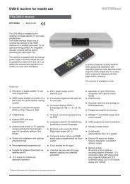
� Für <strong>ein</strong>en <strong>ein</strong>wandfreien Empfang muss <strong>ein</strong>e freie<br />
„Sicht“ in Richtung Süden (+/- 20°) gewährleistet<br />
s<strong>ein</strong>, bei <strong>ein</strong>er Erhebung von etwa 30°. Dann stehen<br />
Ihnen folgende Satelliten zur Auswahl:<br />
1 TÜRKSAT Position 42° Ost<br />
2 ASTRA 2 Position 28,2° Ost<br />
3 ASTRA 3 Position 23,5° Ost<br />
4 ASTRA 1 Position 19,2 Ost<br />
5 EUTELSAT W2 Position 16° Ost<br />
6 EUTELSAT HOTBIRD Position 13° Ost<br />
7 EUTELSAT W1 Position 10° Ost<br />
8 EUTELSAT W3 Position 7° Ost<br />
9 Thor Position 1° West<br />
10 Telecom Position 5° West<br />
11 HISPA-Sat Position 30° West<br />
� Achten Sie darauf, dass sich k<strong>ein</strong>e Hindernisse<br />
zwischen der <strong>Parabolantenne</strong> und dem jeweiligen<br />
Satelliten befinden (z. B. Bäume, Dach- <strong>oder</strong><br />
Hausecken, andere Antennen).<br />
Diese können den Empfang so be<strong>ein</strong>trächtigen, dass<br />
dieser bei ungünstiger Witterungslage völlig ausfällt.<br />
4. Montageort wählen<br />
Der richtige Montageort ist entscheidend dafür, ob Ihre<br />
<strong>Parabolantenne</strong> sicher aufgebaut und optimal<br />
funktionieren kann.<br />
Bei der Montageortwahl sind bauwerkstypische<br />
Besonderheiten zu berücksichtigen. Bei Montage an<br />
Dach- und Gebäudekanten und zylindrischen Bauwerken<br />
ist gemäß DIN 1055, Teil 4 bzw. 4131, mit erhöhten<br />
Wind- <strong>oder</strong> Schwingungsbelastungen zu rechnen.<br />
Die dynamischen Eigenschaften der Antenne und des<br />
Bauwerks können sich gegenseitig be<strong>ein</strong>flussen und<br />
negativ verändern.<br />
Bei Nichtbeachtung kann <strong>ein</strong>e Überschreitung der unter<br />
Punkt 2 genannten Grenzbelastung <strong>oder</strong><br />
Schwingungsfestigkeit auftreten.<br />
Die <strong>Parabolantenne</strong> muss nicht unbedingt auf das Dach,<br />
weil es nicht auf die Höhe über Grund ankommt,<br />
sondern nur auf die freie „Sicht“ zum Satelliten. Deshalb<br />
kann <strong>ein</strong> geeigneter Montageort zum Beispiel auch im<br />
Garten, auf dem Balkon, auf der Terrasse, an <strong>ein</strong>er<br />
Fassade <strong>oder</strong> an <strong>ein</strong>er Garage zu finden s<strong>ein</strong>.<br />
Wenn also möglich, sollten Sie besser nicht auf dem<br />
Dach montieren. Sie verringern damit Ihren Arbeitsaufwand<br />
und die Gefahren bei Montagearbeiten auf dem<br />
Dach!<br />
936.2079/A/0206/2.8d
Vorsicht!<br />
Bei der Montage der <strong>Parabolantenne</strong> können<br />
Gefahren für Ihr Leben und Ihre Gesundheit entstehen!<br />
Beachten Sie deshalb:<br />
� Die hier beschriebenen Montageschritte setzen gute<br />
handwerkliche Fähigkeiten und Kenntnisse vom<br />
Materialverhalten bei Wind<strong>ein</strong>wirkung voraus.<br />
Lassen Sie die Arbeiten daher von <strong>ein</strong>em Fachmann<br />
ausführen, wenn Sie nicht selbst über solche<br />
Voraussetzungen verfügen.<br />
� Betreten Sie Dächer <strong>oder</strong> absturzgefährdete Stellen<br />
nur mit <strong>ein</strong>em ordnungsgemäß angelegten intakten<br />
Sicherheitsgurt!<br />
� Vergewissern Sie sich, ob das Dach Ihr Gewicht<br />
aushält. Betreten Sie niemals brüchige <strong>oder</strong><br />
unstabile Flächen! Tragen Sie feste,<br />
rutschhemmende Schuhe!<br />
� Leitern <strong>oder</strong> andere Steighilfen müssen in <strong>ein</strong>wandfreiem<br />
Zustand s<strong>ein</strong>. Bauen Sie k<strong>ein</strong>e waghalsigen<br />
„Klettertürme“!<br />
� Wenn Passanten durch herabfallende Gegenstände<br />
während der Montage gefährdet werden können,<br />
müssen Sie den Gefahrenbereich absperren!<br />
� Achten Sie auf Freileitungen, falls solche in der<br />
Nähe des Montageortes vorbeiführen.<br />
Bei Berührung besteht akute Lebensgefahr!<br />
� Arbeiten Sie niemals bei aufziehendem Gewitter<br />
<strong>oder</strong> während <strong>ein</strong>es Gewitters an Antennenanlagen.<br />
Es besteht Lebensgefahr!<br />
Abb. 3<br />
5. Antenne montieren (Abb. 4)<br />
Achten Sie bei der Montage des Antennenträgers<br />
(Standfuß, Mast <strong>oder</strong> Wandausleger) darauf, dass dieser<br />
senkrecht steht. Andernfalls kann die Ausrichtung der<br />
Antenne auf den Satelliten zu Schwierigkeiten führen.<br />
Abb. 4<br />
a) Anforderungen an den Antennenträger<br />
� Verwenden Sie nur Träger <strong>oder</strong> Tragrohre, die speziell<br />
für Antennenmontage geeignet sind.<br />
Andere Träger <strong>oder</strong> Rohre erfüllen möglicherweise<br />
nicht die erforderlichen Belastungsanforderungen.<br />
� Wählen Sie für die Befestigung der Antennen Rohre<br />
mit <strong>ein</strong>em Durchmesser von 60–90 mm und <strong>ein</strong>er<br />
Wanddicke von mindestens 2 mm.<br />
Kathr<strong>ein</strong> empfiehlt für die Montage folgende Bauteile:<br />
– Ebenerdig: Standfuß ZAS 15<br />
– Wandmontage: Wandhalterung ZAS 16<br />
– Dachmontage: Mastrohr ZAS 03 <strong>oder</strong> ZAS 04<br />
Falls Sie doch auf dem Dach montieren, müssen Sie<br />
beachten, dass, entsprechend EN 50083-1, das<br />
zulässige Moment an der Einspannstellte maximal<br />
1650 Nm betragen darf.<br />
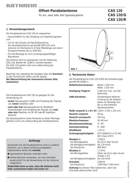
Daraus ergeben sich für die beiden Windlastfälle 1 und 2<br />
die in Abb. 3 aufgeführten maximal zulässigen Mastlängen.<br />
Bei Überschreitung des Moments von 1650 Nm an der<br />
Einspannstelle, z. B. durch <strong>ein</strong>en längeren Mast und<br />
noch zusätzliche montierte Antennen, muss gemäß<br />
EN 50083-1 für die Gewährleistung der Sicherheit der<br />
baulichen Anlage und/<strong>oder</strong> des Gebäudes <strong>ein</strong> Statiker<br />
hinzugezogen werden.<br />
936.2079/A/0206/3.8d
) Halterung montieren (Abb. 5)<br />
� Befestigen Sie die Azimut-/Elevationshalterung<br />
ZAS 120 wie aus der Abbildung ersichtlich.<br />
� Weitere Hinweise zur Montage der Halterung ZAS 120<br />
entnehmen Sie dem dort beiliegenden Anwendungshinweis.<br />
� Falls Sie beabsichtigen, die Antenne nicht auf der<br />
Mastspitze zu montieren, müssen Sie vorher den<br />
Auflagewinkel W von der Halterung abschrauben.<br />
c) Antenne vorbereiten (Abb. 6)<br />
1. Die vier Schrauben aus den Sicherungsholzleisten<br />
herausdrehen.<br />
Entfernen Sie für die weiteren Montageschritte die<br />
Kartonhülle noch nicht. Sie dient zum Schutz der<br />
Speisesystemhalterung.<br />
Den Ausleger soweit herausschwenken bis er am<br />
Kartonrand aufliegt.<br />
2. Parabolspiegel anheben. Dadurch schwenkt der<br />
Ausleger weiter, bis er in die Verriegelung V <strong>ein</strong>rastet.<br />
3. Die vier Schrauben S (SW 19) anziehen.<br />
Anziehdrehmoment 37–43 Nm.<br />
4. Hängen Sie die vorbereitete Antenne in die Halterung<br />
ZAS 120 <strong>ein</strong>.<br />
Abb. 5<br />
Abb. 6<br />
V<br />
�<br />
�<br />
�<br />
W<br />
S<br />
936.2079/A/0206/4.8d
d) Speisesystem (LNB)<br />
Die Speisesysteme sowie Hinweise zu deren Montage<br />
gehören nicht zum Lieferumfang der <strong>Parabolantenne</strong>.<br />
Entnehmen Sie daher die näheren Informationen zur<br />
sachgerechten Montage den Anleitungen, die dem<br />
jeweiligen Speisesystem beiliegen.<br />
Abb. 7<br />
� An der schwenkbaren Haltevorrichtung am Tragarm<br />
können über die Adapterplatte <strong>ein</strong>, <strong>zwei</strong> <strong>oder</strong> <strong>drei</strong><br />
Kathr<strong>ein</strong>-Speisesystem montiert werden. Auf der<br />
Adapterplatte zeigen die Markierungen<br />
– 3 die Montageposition für <strong>ein</strong> Speisesystem,<br />
– 2 und 4 die Montageposition für <strong>zwei</strong> Speisesysteme<br />
(Multifeed) bei 3°– 4° Satellitenabstand,<br />
– 1 und 5 die Montageposition für <strong>zwei</strong><br />
Speisesysteme (Multifeed) bei 6° Satellitenabstand.<br />
Bei Belegung der Positionen 1 und 5 kann auch<br />
zusätzlich mittig auf Position 3 <strong>ein</strong> Speisesystem<br />
montiert werden (3 Satelliten mit jeweils 3° Abstand)<br />
Abb. 8<br />
� Beispiel für Montagepositionen bei Multifeed-<br />
Anwendung mit 3°-4° Satellitenabstand.<br />
Pos. 2 Pos. 4<br />
ASTRA 19,2° Ost + EUTELSAT 16° Ost<br />
ASTRA 23,5° Ost + ASTRA 19,2° Ost<br />
EUTELSAT 16° Ost + HOTBIRD 13° Ost<br />
HOTBIRD 13° Ost + EUTELSAT 10° Ost<br />
EUTELSAT 10° Ost + EUTELSAT 7° Ost<br />
mit 6° Satellitenabstand.<br />
Pos. 1 (Pos. 3) Pos. 5<br />
ASTRA 23,5° Ost + (ASTRA 19,2° Ost) + EUTELSAT 16° Ost<br />
ASTRA 19,2° Ost + (EUTELSAT 16° Ost) + HOTBIRD 13° Ost<br />
EUTELSAT 16° Ost + (HOTBIRD 13° Ost) + EUTELSAT 10° Ost<br />
HOTBIRD 13° Ost + (EUTELSAT 10° Ost) + EUTELSAT 7° Ost<br />
Tipp! Bei Multifeed-Anwendungen sollte die Antenne<br />
auf den Satelliten ausgerichtet werden, der die pegelschwächsten<br />
Signale sendet.<br />
Abb. 7<br />
Satellit<br />
A<br />
Abb. 8<br />
B A<br />
Satellit<br />
B<br />
936.2079/A/0206/5.8d
6. Polarisationsvor<strong>ein</strong>stellung (Abb. 9)<br />
� Ein Speisesystem (Monofeed)<br />
In Abhängigkeit Ihres Standortes und der Position des<br />
zu empfangenden Satelliten stellen Sie am<br />
Speisesystem den Polarisationswinkel entsprechend<br />
Tabelle (siehe Speisesystem) <strong>ein</strong>.<br />
Die schwenkbare Haltevorrichtung H verbleibt dabei in<br />
der Nullposition.<br />
� Mehrere Speisesysteme (Multifeed)<br />
Bei Multifeed-Anordnung ist die schwenkbare<br />
Haltevorrichtung H entsprechend beiliegender Azimut-<br />
/Elevationstabelle für Multifeed-Anwendung um den<br />
Winkel V zu schwenken. In diesem Falle ist der<br />
Polarisationswinkel am Speisesystem nicht nach<br />
dieser Tabelle, sondern nach <strong>ein</strong>em zu berechnenden<br />
Korrekturwinkel <strong>ein</strong>zustellen:<br />
PWNEU =PWTAB - V<br />
7. Antenne ausrichten (Abb. 10)<br />
Die Antenne muss sowohl von der Richtung (Azimut),<br />
als auch von der Neigung (Elevation) her genau auf den<br />
Satelliten ausgerichtet s<strong>ein</strong>. Bei Multifeed-Lösungen<br />
sollte die Antenne auf den Satelliten mit dem<br />
schwächsten Signalpegel ausgerichtet werden.<br />
a) Neigung (Elevation) <strong>ein</strong>stellen<br />
� Beim Schwenken der Antenne um die Elelvationsachse<br />
müssen die 6 Schrauben A locker s<strong>ein</strong>.<br />
� Wenn Sie die Antenne per Hand leicht ankippen,<br />
können Sie zum Grob- <strong>oder</strong> Vor<strong>ein</strong>stellen des<br />
Elevationswinkels die Mutter B (für F<strong>ein</strong><strong>ein</strong>stellung)<br />
schneller drehen.<br />
� Stellen Sie nun die Neigung <strong>ein</strong>. Den genauen<br />
Elevationswinkel für Ihren Standort finden Sie in der<br />
Anleitung für das Speisesystem. Stellen Sie diesen<br />
Winkel an der Skala (10° bis 50°) <strong>ein</strong>. Dabei muss der<br />
entsprechende Skalenstrich auf der Halterung mit der<br />
Kante C des Reflektorhaltebleches fluchten.<br />
� Ziehen Sie die Schrauben A leicht an.<br />
Abb. 9<br />
Abb. 10<br />
936.2079/A/0206/6.8d
) Richtung (Azimut) <strong>ein</strong>stellen<br />
Für die folgenden Schritte benötigen Sie gegebenenfalls<br />
<strong>ein</strong>en Helfer, falls Sie nicht selbst an <strong>ein</strong>em Antennen-<br />
Messgerät <strong>oder</strong> Bildschirm mit angeschlossenem<br />
Satelliten-Receiver das Ergebnis der Ausrichtarbeiten<br />
beobachten können.<br />
� Stellen Sie am Satelliten-Receiver <strong>ein</strong>en bekannten<br />
Programmplatz <strong>ein</strong>, um kontrollieren zu können, ob Sie<br />
auch wirklich den gewünschten Satelliten<br />
”getroffen” haben.<br />
� Drehen Sie die Antenne grob in Richtung Süden.<br />
Drehen Sie danach die Antenne langsam um die<br />
Mastachse – nach links und rechts, bis das <strong>ein</strong>gestellte<br />
Programm am besten zu empfangen ist.<br />
c) F<strong>ein</strong><strong>ein</strong>stellung<br />
� Lösen Sie die Schrauben A der Elevationsfixierung.<br />
� Schwenken Sie die Antenne leicht nach oben und<br />
nach unten durch Drehen der F<strong>ein</strong><strong>ein</strong>stellmutter B, bis<br />
Sie<br />
– entweder am Antennen-Messgerät das stärkste Signal<br />
messen<br />
– <strong>oder</strong> bei optischer Beurteilung am Bildschirm den<br />
besten Bild<strong>ein</strong>druck erzielen (nur bei Analogempfang):<br />
Hierzu schwenken Sie die Antenne soweit nach oben<br />
und unten, bis Sie jeweils an die Grenze kommen, wo<br />
die ersten sogenannten „Fischchen“ (Spikes) am<br />
Bildschirm ersch<strong>ein</strong>en. Stellen Sie die Antenne dann in<br />
die Mitte zwischen diesen beiden Grenzpunkten.<br />
� Korrigieren Sie nun abwechselnd die Richtung<br />
(Azimut) und Neigung (Elevation), bis sich das Mess<strong>oder</strong><br />
Bildergebnis nicht mehr verbessert.<br />
Hinweis: Beim Festdrehen der Flügelmuttern an den<br />
<strong>zwei</strong> Schließschellen der Halterung kann sich die<br />
Antenne leicht verdrehen! Dies sollten Sie bei der<br />
F<strong>ein</strong><strong>ein</strong>stellung beachten (und eventuell für <strong>ein</strong>e ganz<br />
genaue Einstellung ausnutzen).<br />
Gegebenenfalls optimieren Sie am Ende nochmals den<br />
(die) Polarisationswinkel des (der) Speisesystem(e)s und<br />
den Winkel der schwenkbaren Haltevorrichtung zur<br />
Speisesystembefestigung.<br />
d) Antenne endgültig festschrauben<br />
Ziehen Sie am Ende alle Schraubverbindungen fest.<br />
Kontrollieren Sie zum Schluss noch <strong>ein</strong>mal alle<br />
Schraubverbindungen auf festen Sitz.<br />
Die Antennenkabel sind an solchen Stellen mit<br />
Kabelbindern zu befestigen, wo die Gefahr besteht, dass<br />
sie durch Windbewegungen scheuern und dadurch<br />
beschädigt werden können.<br />
Achtung!<br />
Kontrollieren Sie nach außergewöhnlichen<br />
Belastungen (schweren Stürmen, ungewöhnlich<br />
starke Vereisung, außergewöhnlichen<br />
Vorkommnissen) den Befestigungszustand<br />
der Antenne.<br />
936.2079/A/0206/7.8d
Warnung!<br />
Erdungs- und Blitzschutzarbeiten dürfen wegen<br />
der Gefahr unzulänglicher Arbeitsergebnisse nur<br />
von hierfür speziell geschulten Fachkräften des<br />
Elektrohandwerks ausgeführt werden!<br />
� Führen Sie niemals Erdungs- und Blitzschutzarbeiten<br />
durch, wenn Sie nicht selbst Fachkraft mit<br />
entsprechenden Kenntnissen sind!<br />
Die hier abgedruckten Hinweise sind k<strong>ein</strong>e Aufforderung<br />
an Nichtfachleute, Erdungs- und<br />
Blitzschutzarbeiten in eigener Verantwortung durchzuführen,<br />
sondern dienen der von Ihnen beauftragten<br />
Fachkraft als zusätzliche Information!<br />
7. Antenne erden/Blitzschutz<br />
Die Antenne muss geerdet werden, so fordert es die<br />
EN 50083-1. Hiervon ausgenommen sind nur solche<br />
Außenantennen,<br />
– die mehr als 2 m unterhalb der Dachkante<br />
– und zugleich weniger als 1,5 m von Gebäuden<br />
angebracht sind.<br />
Ungeachtet dessen empfiehlt Kathr<strong>ein</strong> generell aus<br />
Sicherheitsgründen <strong>ein</strong>en Potenzialausgleich<br />
vorzunehmen.<br />
Gefahren können nicht nur durch Gewitter entstehen<br />
(Blitzschlag), sondern auch durch statische Aufladung<br />
<strong>oder</strong> Kurzschluss in den angeschlossenen Geräten:<br />
� Deshalb müssen der Mast und die Außenleiter der<br />
Antennenkabel auf kürzestem Weg senkrecht über<br />
<strong>ein</strong>en geeigneten Erdungsleiter mit der Blitzschutzanlage<br />
des Gebäudes verbunden s<strong>ein</strong> (falls k<strong>ein</strong>e<br />
Blitzschutzanlage vorhanden ist: mit der Gebäudeerdung).<br />
a) Geeignet als Erdungsleiter<br />
– ist <strong>ein</strong> Einzelmassivdraht mit <strong>ein</strong>em Querschnitt von<br />
min. 16 mm2 Kupfer, min. 25 mm2 Aluminium <strong>oder</strong> min.<br />
50 mm2 Stahl<br />
– <strong>oder</strong> metallische Hausinstallationen (z. B. durchgehende<br />
Metallrohre der Wasser- <strong>oder</strong> Heizungsanlage),<br />
sofern diese vom Querschnitt und der<br />
Dauerhaftigkeit der elektrischen Verbindung her<br />
mindestens den Anforderungen an Erdungsleiter<br />
entsprechen.<br />
b) Nicht geeignet als Erdungsleiter<br />
– sind die Außenleiter der Antennenkabel<br />
– <strong>oder</strong> Schutzleiter <strong>oder</strong> Neutralleiter des<br />
Starkstromnetztes.<br />
Erdungsleitung<br />
Erdungsanschluss<br />
Potenzialausgleichleitung<br />
Im schraffierten Bereich<br />
ist lt. Norm <strong>ein</strong>e<br />
Antennenerdung nicht<br />
zwingend erforderlich.<br />
Potenzialausgleichsschiene<br />
Netzanschluss<br />
230 V<br />
Potenzialausgleichleitung<br />
Potenzialausgleichsschiene<br />
c) Führung von Erdungsleitern<br />
� Antennenkabel und Erdungsleiter dürfen nicht durch<br />
Räume geführt werden, die zur Lagerung von leicht<br />
entzündlichen Stoffen dienen (z. B. Heu, Stroh) <strong>oder</strong> in<br />
denen sich <strong>ein</strong>e explosive Atmosphäre bilden kann<br />
(z. B. Gase, Dämpfe).<br />
� Bei Verwendung der <strong>Parabolantenne</strong> in kompletten<br />
Antennenanlagen (z. B. Verteilanlagen) müssen zudem<br />
die Erdungsmaßnahmen so ausgeführt s<strong>ein</strong>, dass der<br />
Erdungsschutz auch dann bestehen bleibt, wenn <strong>ein</strong>zelne<br />
Einheiten entfernt <strong>oder</strong> ausgetauscht werden.<br />
KATHREIN-Werke KG · Anton-Kathr<strong>ein</strong>-Straße 1–3 · Postfach 10 04 44 · D-83004 Rosenheim · Deutschland · Telefon (0 80 31) 18 40 · Telefax (0 80 31) 18 43 06<br />
936.2079/A/0206/8.8d/SKS Technische Änderungen vorbehalten.
1. Intended use<br />
The parabolic antenna CAS 120 is exclusively destined<br />
for:<br />
– reception of satellite signals<br />
and<br />
– utilisation as a domestic antenna.<br />
A domestic or private antenna is defined acc. to<br />
DIN 4131 as an antenna with a free mast length of 6 m<br />
and a bending moment at the fixing point of up to<br />
1650 Nm.<br />
– installation on buildings not subject to oscillations.<br />
The antenna may only be mounted with the support<br />
ZAS 120, order. no 218672.<br />
The ZAS 120 is not included in the scope of delivery of<br />
the parabolic antenna.<br />
It is important to observe the maximum load as<br />
mentioned in the technical data (right column).<br />
If that value is exceeded, antenna parts can break<br />
loose!<br />
The parabolic antenna CAS 120 can be equipped with<br />
– one feed system (LNB) for reception of signals from<br />
one satellite.<br />
– two or three feed systems for multifeed reception from<br />
two or three satellites 3°–4° or 6° apart.<br />
Neither the feed systems nor the mounting instructions<br />
for the feed systems are included in the scope of delivery<br />
of the antenna.<br />
Attention!<br />
Do not use the parabolic antenna for purposes other<br />
than mentioned in these instructions.<br />
Never<br />
● modify any antenna parts or<br />
● use different components than those specifically<br />
recommended by the manufacturer for use with<br />
these antennas.<br />
As a result of that, the stability and security of the<br />
antenna can be affected.<br />
<strong>Offset</strong> parabolic antenna CAS 120<br />
for one, two or three feed systems CAS 120/G<br />
CAS 120/R<br />
Fig. 1<br />
2. Technical data<br />
The parabolic antennas CAS 120 complies with the<br />
specifications acc. to DIN EN 50083-1.<br />
Diameter of reflector: Width: 1234 mm<br />
Height: 1335 mm<br />
Length of the support arm: 1160 mm max. from<br />
centre of mast<br />
LNB support: Swivelling support for the<br />
adapter plate for mounting<br />
up to 3 Kathr<strong>ein</strong> feed<br />
systems<br />
Measurements (packed): 1500 x 1335 x 225 mm<br />
Weight (packed): 29 kg<br />
Weight (unpacked): 18.5 kg<br />
Diameter of mast: 50-90 mm<br />
Elevation angle: 5°-50°<br />
Azimuth angle: 0°-360°<br />
Wind surface area: 1.35 m 2<br />
Vibration immunity: ETS 300019-2-4 (12.94)<br />
IEC Class 4 M 5<br />
Windload 1: 1296 N<br />
for an installation height: up to 20 m above ground<br />
for a wind velocity: up to 130 km/h<br />
at a dynamic pressure: 800 N/m 2<br />
Windload 2: 1776 N<br />
for an installation height: higher than 20 m above<br />
ground (factor 1.37)<br />
for a wind velocity: up to 150 km/h<br />
Maximum load: 2646 N<br />
at a dynamic pressure: 1900 N/m 2 (190 km/h)<br />
Attention! If the max. load is exceeded, antenna parts<br />
can break loose!<br />
936.2079/A/0206/1.8e
3. Before you…<br />
begin to install, connect or utilise the parabolic antenna,<br />
observe the information you find in these mounting<br />
instructions. If you fail to pay attention to the information,<br />
one cannot exclude<br />
� that due to wrong installation and connecting, or because<br />
of having modified components or using other<br />
components, the antenna or the mounting place will<br />
be damaged.<br />
� that because of inappropriate behaviour, risks for your<br />
and other people's health and life will be created.<br />
� that the manufacturer will decline the liability for faulty<br />
function and resulted damages.<br />
It is most important that you are aware of the<br />
responsibility you have for your own and other people's<br />
safety when working on the antenna system!<br />
Retain these instructions for possible later use<br />
when questions come up. In case you sell the antenna,<br />
pass the instructions on to the new owner.<br />
Attention!<br />
Never install the antenna below overhead power lines.<br />
It can be that the required safety distance is not kept.<br />
Furthermore, make sure that the lateral distance to all<br />
other electrical systems is at least 1 m.<br />
Danger to life exists if you or the antenna make<br />
contact with live parts!<br />
Do not install the antenna on buildings with easily<br />
inflammable roofs (straw, reed or similar material).<br />
This is a fire hazard since the antenna is subject to<br />
static charge and lightning.<br />
Fig. 2<br />
East<br />
South<br />
West<br />
Fig. 2<br />
� For good reception the antenna must have an unobstructed<br />
"visibility" to the south (+/-20). The horizontal<br />
elevation angle must be 30°. The reception of the following<br />
satellites will then be possible:<br />
1 TÜRKSAT Position 42° East<br />
2 ASTRA 2 Position 28.2° East<br />
3 ASTRA 3 Position 23.5° East<br />
4 ASTRA 1 Position 19.2° East<br />
5 EUTELSAT W2 Position 16° East<br />
6 EUTELSAT HOTBIRD Position 13° East<br />
7 EUTELSAT W1 Position 10° East<br />
8 EUTELSAT W3 Position 7° East<br />
9 Thor Position 1° West<br />
10Telecom Position 5° West<br />
11 HISPA-Sat Position 30° West<br />
� Unobstructed "visibility" means that there must be no<br />
obstacles (such as trees, buildings, roofs, balconies or<br />
similar obstacles) between the antenna and the<br />
satellite.<br />
Obstacles of this kind can impair the reception or even<br />
make reception impossible.<br />
4. Mounting site<br />
The selection of the right mounting site for your antenna<br />
is important in order to ensure safe and satisfactory<br />
operation.<br />
When choosing the mounting site, pay attention to<br />
typical characteristics of the building. If the antenna is<br />
installed on the edge of a roof or building, one must<br />
reckon acc. to DIN 1055, Part 4 or 4131 with a higher<br />
wind or oscillation load. This means that the dynamic<br />
characteristics of the antenna and the building can<br />
influence each other and change the characteristics<br />
negatively. Disregard of these circumstances can lead to<br />
exceeding the max. load or dynamic strength mentioned<br />
in sect. 2.<br />
It is not essential to mount the parabolic antenna on the<br />
roof since it is not height above ground that matters but<br />
an unimpeded line-of-sight to the satellite. Thus a<br />
suitable mounting location may be found in the garden,<br />
on the balcony/terrace or on a facade or garage, for<br />
example.<br />
Thus, if at all possible, the roof should be avoided as a<br />
mounting location. In any event this reduces the amount<br />
of work and avoids the dangers of doing installation<br />
work on the roof!<br />
936.2079/A/0206/2.8e
Attention!<br />
The installation work can create dangers for your<br />
health and life.<br />
Therefore:<br />
� The mounting procedure described here demands<br />
skills and a knowledge how the antenna behaves<br />
when b<strong>ein</strong>g subjected to atmospheric conditions.<br />
If you do not have the required skills, ask a<br />
specialist to do the installation work.<br />
� When working on the roof or near to drop away<br />
sites, use a safety belt.<br />
� Make sure that the roof will support your weight.<br />
Wear non-slip shoes!<br />
� Use ladders or other climbing aids that are in perfect<br />
condition.<br />
� If passers-by can be hurt by falling objects, block<br />
the danger area.<br />
� Watch out for overhead power lines. Getting into<br />
contact with these means danger to life!<br />
� Never work on the antenna during a<br />
thunderstorm or when one is approaching.<br />
This can put your life at risk!<br />
Fig. 3<br />
Fixing point<br />
Windload Windload<br />
up to 20 m above ground (> 20 m above ground)<br />
Lmax 1.1 m 0.75 m<br />
5. Installation of the antenna (Fig. 4)<br />
Make sure that the antenna support (foot mount, mast or<br />
wall bracket) is installed in a vertical position, otherwise<br />
the alignment of the antenna to the satellite can create<br />
problems.<br />
Fig. 4<br />
a) Requirements for the antenna support<br />
� Only use masts or supports specially suited to be<br />
used as an antenna support. Other supports often do<br />
not have the necessary strength required for the environmental<br />
conditions.<br />
� Choose a mast that has a diameter of 60-90 mm and<br />
a wall thickness of at least 2 mm.<br />
For mounting, Kathr<strong>ein</strong> Werke KG recommends the<br />
following components:<br />
- Ground mounting: Tripod ZAS 15<br />
- Wall mounting: Wall support ZAS 16<br />
- Roof mounting: Mast ZAS 03 or ZAS 04<br />
When mounting takes place on the roof, keep in mind<br />
that the maximal admissible bending moment on the<br />
fixing point is 1650 Nm according to EN 50083-1.<br />
From this, the maximal admissible mast lengths, which<br />
are listed in Fig. 3, are determined for windload 1 and<br />
windload 2.<br />
In the case of a greater bending moment than 1650 Nm<br />
on the fixing point, for example, due to a longer mast<br />
and additionally mounted antennas, a static engineer is<br />
required to guarantee safety of the system and/or<br />
building according to EN 50083-1.<br />
936.2079/A/0206/3.8e
) Mounting the support arm (Fig. 5)<br />
� Mount the azimuth/elevation support arm ZAS 120 on<br />
the mast as shown in the drawing.<br />
� Refer to the operating instructions supplied with the<br />
ZAS 120 for more information regarding installation.<br />
� If you do not intend to mount the antenna on the top<br />
of the mast, you must first remove the support angle<br />
W from the support arm.<br />
c) Preparing the antenna (Fig. 6)<br />
1. Remove the four screws from the protective strip of<br />
wood.<br />
For the following mounting steps, do not remove the<br />
carton yet. It protects the feed system support.<br />
Swing out the arm until it lies on the edge of the<br />
carton.<br />
2. Lift up the parabolic antenna. The arm continues to<br />
swing out until it is fixed in the lock V.<br />
3. Tighten the four screws S (SW 19).<br />
Tightening torque 37-43 Nm.<br />
4. Connect the prepared antenna to the support<br />
ZAS 120.<br />
Fig. 5<br />
Fig. 6<br />
Installation on top of mast Installation in front of mast<br />
V<br />
�<br />
�<br />
�<br />
W<br />
Remove<br />
S<br />
936.2079/A/0206/4.8e
d) Feed system (LNB)<br />
The feed systems and their mounting instructions are not<br />
in the scope of the delivery of the parabolic antenna.<br />
Detailed information for the correct installation is<br />
supplied together with each feed system.<br />
Fig. 7<br />
� One, two or three Kathr<strong>ein</strong> feed systems can be<br />
mounted on the swivelling multifeed support on the<br />
support arm via the adapter plate! The marking on the<br />
adapter plate indicates<br />
– 3 as the mounting position for one feed system,<br />
– 2 and 4 as the mounting positions for two multifeed<br />
systems allowing signal reception from satellites<br />
3°-4° apart,<br />
– 1 and 5 as the mounting positions for two multifeed<br />
systems allowing signal reception from satellites<br />
6° apart.<br />
When using positions 1 and 5, a feed system can also<br />
be additionally mounted in the middle on position 3<br />
(3 satellites 3° apart).<br />
Fig. 8<br />
� Example for mounting positions for multifeed<br />
reception with satellites 3°-4° apart.<br />
Pos. 2 Pos. 4<br />
ASTRA 19,2° East + EUTELSAT 16° East<br />
ASTRA 23,5° East + ASTRA 19,2° East<br />
EUTELSAT 16° East + HOTBIRD 13° East<br />
HOTBIRD 13° East + EUTELSAT 10° East<br />
EUTELSAT 10° East + EUTELSAT 7° East<br />
with satellites 6° apart.<br />
Pos. 1 (Pos. 3) Pos. 5<br />
ASTRA 23,5° East + (ASTRA 19,2° East) + EUTELSAT 16° East<br />
ASTRA 19,2° East + (EUTELSAT 16° East) + HOTBIRD 13° East<br />
EUTELSAT 16° East + (HOTBIRD 13° East) + EUTELSAT 10° East<br />
HOTBIRD 13° East + (EUTELSAT 10° East) + EUTELSAT 7° East<br />
Tip! With multifeed applications the antenna should<br />
be aligned to the satellite with the weaker signal level.<br />
Fig. 7<br />
Satellite<br />
A<br />
Fig. 8<br />
B A<br />
Satellite<br />
B<br />
936.2079/A/0206/5.8e
5. Setting polarisation angle (Fig. 9)<br />
� One feed system (mono feed)<br />
Adjust the polarisation angle according to the tables<br />
(see feed system) on the feed system depending on<br />
your mounting site and the position of the received<br />
satellites.<br />
The swivelling support H remains in the zero position.<br />
� Mounting several feed systems (multifeed)<br />
For multifeed reception, the swivelling support H must<br />
be moved to the angel V according to the supplied<br />
azimuth/elevation table for multifeed reception. In this<br />
case, the polarisation angle on the feed system is not<br />
adjusted according to this table, but rather to the calculated<br />
correction angle :<br />
PWNEW =PWTAB - V<br />
7. Aligning the antenna (Fig. 10)<br />
With regard to the direction (Azimuth) and the inclination<br />
(Elevation), the antenna must be accurately aligned to<br />
the satellite. For multifeed reception, it is necessary to<br />
align the antenna to the satellite with the weaker signal<br />
level.<br />
a) Setting the inclination (Elevation)<br />
� When setting the elevation of the antenna, loosen the<br />
6 screws A on the elevation scale.<br />
� When you lightly tilt the antenna by hand, you can turn<br />
the nut B (for fine adjustment) faster for rough adjustment<br />
or pre-adjustment of the elevation angle.<br />
� Now set the elevation. You find the correct angle of<br />
the elevation for your mounting site in the mounting<br />
instructions supplied with the feed system. Set this<br />
angle on the scale (10° to 50°). Here, the respective<br />
scale line on the support must be aligned with the<br />
edge C of the reflector support sheet.<br />
� Lightly screw on the screws A.<br />
Fig. 9<br />
Fig. 10<br />
Sense of rotation for polarisation angle<br />
Sense of rotation for the angle V for swivelling part<br />
936.2079/A/0206/6.8e
) Setting the direction (Azimuth)<br />
For the following steps you need an assistant if you<br />
cannot operate an antenna measuring instrument nor<br />
watch on your television set which you have connected<br />
to a satellite receiver the result of your alignment work.<br />
� Select on your satellite receiver a programme well<br />
known in order to make sure you are aligned to the<br />
desired satellite.<br />
� Roughly align the antenna towards the south.<br />
Then slowly turn the antenna around the mast axle to<br />
the left and then to the right, until you obtain the best<br />
picture for the chosen programme.<br />
c) Fine alignment<br />
� Loosen again the screws A on the elevation scale.<br />
� Move the antenna slightly up and down by turning the<br />
fine wing nut B, until<br />
– the strongest signal is shown on the measuring<br />
instrument<br />
– or best picture quality is obtained on the TV set<br />
(only for analogue reception): Move the antenna slightly<br />
up and down until you see the first "spikes" on the<br />
screen of your TV set. The best picture quality will be<br />
found in the middle of these boundary positions.<br />
� Now alternately correct the direction (Azimuth) and the<br />
inclination (Elevation) until there is no more<br />
improvement of the measured value or the picture<br />
quality.<br />
Note: On tightening-up the nuts on the mast clamp, a<br />
slight movement of the antenna may occur! You need to<br />
take this into account during fine adjustment (and exploit<br />
it to get a very precise adjustment if need be).<br />
Also, optimise the polarisation angle(s) of the feed<br />
system(s) and the angle of the swivelling support once<br />
more.<br />
d) Final tightening up of antenna<br />
Finally, tighten all screws.<br />
Check again that all screw connections have been done<br />
properly.<br />
Secure the cable using cable ties along the full length of<br />
the antenna carrier so that it does not chafe and sustain<br />
damage due to wind effects.<br />
West<br />
Azimuth angle<br />
Zenith<br />
Horizon<br />
Elevation angle<br />
East<br />
South<br />
Attention!<br />
Check if the antenna is properly secured after<br />
unusual conditions (bad storms, heavy ice<br />
build-up, etc.).<br />
936.2079/A/0206/7.8e
Attention!<br />
Due to the danger of inadequate results from<br />
grounding and lightning conductor work, only<br />
electricians with the requisite specialised training<br />
must undertake this!<br />
� Never undertake grounding and lightning conductor<br />
work yourself unless you are a specialist with the<br />
necessary know-how!<br />
The instructions supplied here are not an invitation to<br />
non-specialists to take responsibility for carrying out<br />
grounding and lightning conductor work themselves,<br />
but serve as additional information for the specialist.<br />
7. Antenna grounding/Lightning protection<br />
The antenna must be grounded as is required by<br />
standard DIN EN 50083-1. The only external antennas<br />
exempted from this are those:<br />
– fitted more than 2 metres below the crest of the roof<br />
– and also less than 1.5 metres from the building.<br />
However, for safety reasons Kathr<strong>ein</strong> recommends to<br />
mount a potential equalisation device.<br />
Danger can arise not just from thunderstorms (lightning<br />
strikes) but also through static charge accumulation or<br />
discharge in the devices attached:<br />
� Consequently, the mast and the external conductor of<br />
the antenna cable must be connected to the building's<br />
lightning conductor system taking the shortest path<br />
vertically via a suitable grounding conductor (or to the<br />
building's grounding system if no lightning conductor<br />
system is available).<br />
a) Suitable as grounding conductor:<br />
– a single solid wire with a min. cross-section of at least<br />
16 mm 2 for copper, 25 mm 2 for aluminium or 50 mm 2<br />
for steel<br />
– or metallic domestic installations (continuous metallic<br />
water or heating system pipes, for example) provided<br />
that they at least meet the requirements for grounding<br />
conductors in terms of cross-section and permanence<br />
of the electrical connection.<br />
b) Not suitable as grounding conductor:<br />
– the external conductors of the antenna cable<br />
– or the grounding conductor or neutral conductor of the<br />
power system<br />
Grounding<br />
conductor<br />
Grounding<br />
connection<br />
Equipotential<br />
bonding<br />
conductor<br />
Grounding the antenna<br />
installed in the hatched<br />
area is not explicitly<br />
required by standard<br />
Equipotential bonding strip<br />
Mains connection<br />
230 V<br />
Equipotential<br />
bonding<br />
conductor<br />
Equipotential bonding strip<br />
c) Routing of grounding conductors<br />
� Antenna cables and grounding conductors must not<br />
be routed through rooms used for storing easily inflammable<br />
substances (hay or straw, for example) or in<br />
which an explosive atmosphere can develop (gases,<br />
vapours).<br />
� If the parabolic antenna is used in integrated antenna<br />
systems (e. g. distribution systems), the grounding<br />
measures must also be designed in such a way that<br />
grounding protection is still maintained if individual<br />
units are removed or replaced.<br />
KATHREIN-Werke KG · Anton-Kathr<strong>ein</strong>-Straße 1–3 · Postfach 10 04 44 · D-83004 Rosenheim · Deutschland · Telefon (0 80 31) 18 40 · Telefax (0 80 31) 18 43 06<br />
936.2079/A/0206/8.8e/SKS Subject to technical modifications.
1. Objectif<br />
L’antenne parabolique CAS 120 est prévue:<br />
– exclusivement pour la réception de signaux satellite<br />
et<br />
– uniquement en tant qu’antenne domestique.<br />
Selon la norme DIN 4131, la longueur du mât d’une<br />
antenne domestique ne doit pas dépasser 6 m et son<br />
moment de flexion doit être inférieur à 1650 Nm.<br />
– pour le montage sur des supports non susceptibles<br />
d’osciller.<br />
L’antenne doit être installée seulement conjointement<br />
avec le support ZAS 120, Réf. 218672. Le support n’est<br />
pas livré avec l’antenne parabolique.<br />
Tenez compte impérativement des indications relatives à<br />
la charge limite mentionnées dans les caractéristiques<br />
techniques (colonne ci-contre).<br />
En cas de dépassement, bris de pièces possible!<br />
L’antenne parabolique CAS 120 est utilisable avec<br />
– une tête SHF (LNB) pour la réception des signaux<br />
d’une position de satellite<br />
– deux ou trois têtes SHF pour réception multisatellite<br />
des signaux de deux ou trois positions satellite<br />
séparées d’un écart de 3°–4° ou 6°.<br />
Les têtes SHF et les instructions pour le montage ne<br />
sont pas livrées avec l’antenne parabolique.<br />
Attention!<br />
N’employez pas l’antenne parabolique pour d’autres<br />
buts que ceux indiqués dans cette notice.<br />
En particulier, vous ne devez jamais<br />
● modifier quelque pièce que ce soit ou<br />
● employer d’autres pièces que celles prévues par le<br />
fabricant.<br />
Dans le cas contraire, cela peut compromettre la<br />
stabilité et la sécurité de l’antenne!<br />
Antenna parabolique offset CAS 120<br />
prévue pour une, deux ou trois têtes SHF CAS 120/G<br />
CAS 120/R<br />
Fig. 1<br />
2. Caractéristiques techniques<br />
L’antenne parabolique CAS 120 satisfait aux exigences<br />
de la norme EN 50083-1.<br />
Diamètre du réflecteur: Largeur: 1234 mm<br />
Hauteur: 1335 mm<br />
Longueur du bras support: 1160 mm max. du milieu<br />
du mât<br />
Support pour LNB: Support orientable pour<br />
la plaque adaptateur qui<br />
permet de monter jusqu’à<br />
3 têtes SHF Kathr<strong>ein</strong><br />
Dimensions emballé (L x I x H): 1500 x 1335 x 225 mm<br />
Poids brut: 29 kg<br />
Poids net: 18,5 kg<br />
Diamètre du mât: 50-90 mm<br />
Réglage de l’élévation: 5°-50°<br />
Réglage de l’azimut: 0°-360°<br />
Surface au vent: 1,35 m 2<br />
Résistance aux oscillations: ETS 300019-2-4 (12.94)<br />
IEC Class 4 M 5<br />
Charge au vent 1: 1296 N<br />
si montage en hauteur: jusqu’à 20 m au-dessus<br />
du sol<br />
avec vitesse du vent: jusqu’à 130 km/h<br />
avec pression dynamique: 800 N/m 2<br />
Charge au vent 2: 1776 N<br />
si montage en hauteur: supérieur à 20 m au<br />
dessus du sol<br />
(facteur 1,37)<br />
avec vitesse du vent: jusqu’à150 km/h<br />
Charge limite: 2646 N<br />
avec pression dynamique: 1900 N/m 2 (190 km/h)<br />
Attention! Bris de pièces possible en cas de<br />
dépassement de la charge limite!<br />
936.2079/A/0206/1.8f
3. Conseils préliminaires<br />
Avant de monter, brancher ou employer l’antenne<br />
parabolique, observez obligatoirement les conseils de<br />
cette notice! Dans le cas contraire,<br />
● des erreurs de montage ou de branchement peuvent<br />
abîmer l’antenne ou endommager le lieu de montage,<br />
● votre santé ou votre vie peuvent être mises en danger<br />
suite à un comportement inadapté,<br />
● le fabricant n’assume aucune responsabilité pour<br />
les dégâts et dysfonctionnements en résultant.<br />
Lors de travaux sur des antennes, veuillez prendre en<br />
considération votre responsabilité envers toute autre<br />
personne.<br />
Conservez la notice pour pouvoir la consulter plus tard si<br />
nécessaire et, en cas de vente, remettez-la au nouveau<br />
propriétaire.<br />
Attention!<br />
Vous ne devez en aucun cas monter l’antenne en<br />
dessous de lignes électriques aériennes, sinon il se<br />
peut que les écarts obligatoirement nécessaires ne<br />
soient pas respectés.<br />
Maintenez également sur les côtés un écart d’au<br />
moins 1 m avec toutes les autres installations électriques!<br />
Danger de mort si des pièces métalliques de<br />
l’antenne touchent des installations électriques:<br />
Ne montez jamais l’antenne sur des bâtiments avec<br />
des couvertures de toit facilement inflammables,<br />
comme p. ex. paille, chaume ou autres matériaux<br />
semblables! Dans le cas contraire, il y a des risques<br />
d’incendie en cas de surtensions atmosphériques<br />
(chargement d’électricité statique) ou de foudre<br />
(p. ex. orage).<br />
Fig. 2<br />
Est<br />
Sud<br />
Ouest<br />
Fig. 2<br />
� Pour une réception parfaite, vous devez vous assurer<br />
d’avoir une „vue“ dégagée en direction du sud<br />
(+/-20°) avec une inclinaison d’environ +30°. Vous<br />
avez alors le choix parmi les satellites suivants:<br />
1 TÜRKSAT Position 42° Est<br />
2 ASTRA 2 Position 28.2° Est<br />
3 ASTRA 3 Position 23.5° Est<br />
4 ASTRA 1 Position 19.2° Est<br />
5 EUTELSAT W2 Position 16° Est<br />
6 EUTELSAT HOTBIRD Position 13° Est<br />
7 EUTELSAT W1 Position 10° Est<br />
8 EUTELSAT W3 Position 7° Est<br />
9 Thor Position 1° Ouest<br />
10 Telecom Position 5° Ouest<br />
11 HISPA-Sat Position 30° Ouest<br />
● Veillez à ce qu’il n’y ait pas d’obstacles entre l’antenne<br />
parabolique et le satellite voulu (p. ex. des arbres, un<br />
coin de toit ou de maison, d’autres antennes).<br />
Cela pourrait perturber la réception au point qu’en cas<br />
de conditions atmosphériques défavorables la<br />
réception ne soit plus du tout possible.<br />
4. Choix du lieu de montage<br />
Le lieu de montage correct est l’élément décisif pour une<br />
installation sûre et un fonctionnement optimale de<br />
l’antenne parabolique.<br />
Tenez compte des caractéristiques du support pour<br />
choisir le lieu de montage. En cas de montage sur les<br />
bords d’un toit ou d’un bâtiment et avec des supports<br />
cylindriques, il convient de tenir compte de charges<br />
élévées dues au vent ou à des oscillations<br />
conformément à la norme DIN 1055, partie 4 ou DIN<br />
4131.<br />
Les caractéristiques dynamiques de l’antenne et du<br />
support peuvent s’influencer et interagir négativement.<br />
En cas de non-observation, il peut se produire un<br />
dépassement de la charge limite mentionnée au point 2<br />
ou de la résistance aux oscillations.<br />
L’antenne parabolique ne doit pas obligatoirement être<br />
montée sur le toit, car ce qui compte n’est pas la hauteur<br />
au-dessus du sol mais uniquement la „vue“ dégagée<br />
vers le satellite. C’est pourquoi un lieu de montage<br />
approprié peut se trouver également dans le jardin, sur le<br />
balcon, sur la terrasse, sur une façade ou sur le mur d’un<br />
garage.<br />
Si cela est possible, vous devriez au mieux éviter de<br />
monter sur le toit. Aprés tout, vous aurez moins de<br />
travail et moins de risques qu’avec une installation de<br />
l’antenne sur le toit!<br />
936.2079/A/0206/2.8f
Attention!<br />
Lors du montage de l’antenne parabolique, votre<br />
santé et votre vie peuvent être mises en danger!<br />
C’est pourquoi observez ceci:<br />
� Les étapes de montage décrites ici présupposent<br />
de bonnes capacités de bricolage et la connaissance<br />
du comportement des matériaux sous<br />
l’influence du vent. Demandez à un spécialiste de<br />
réaliser ces travaux si vous ne disposez pas<br />
vous-même de ces facultés.<br />
� Déplacez-vous sur les toits ou à des endroits avec<br />
des risques de chute uniquement après avoir mis<br />
une cinture de sécurité en bon état.<br />
� Assurez-vous que le toit puisse supporter votre<br />
poids. Ne marchez jamais sur des surfaces fragiles<br />
ou instables! Portez des chaussures fermées et<br />
antidérapantes!<br />
� Les échelles ou moyens d’escalade doivent être en<br />
parfait état. Ne construisez pas d’échafaudage<br />
hasardeux!<br />
� Si des passants peuvent être mis en danger par des<br />
objets tombant du toit pendant le montage de l’antenne,<br />
vous devez interdire l’accès à la zone de<br />
danger!<br />
� Faites attention aux lignes électriques aériennes<br />
qui pourraient se trouver à proximité du lieu de<br />
montage. Danger de mort imminent en cas de<br />
contact!<br />
� N’effectuez aucuns travaux sur une antenne en<br />
cas d’orage imminent ou pendant un orage.<br />
Danger de mort!<br />
Fig. 3<br />
Point de fixation<br />
Charge au vent 1 Charge au vent 2<br />
(jusqu’à 20 m au-dessus<br />
du sol)<br />
(> 20 m dessus du sol)<br />
Lmax 1.1 m 0.75 m<br />
5. Montage de l’antenne (Fig. 4)<br />
Faites attention lors du montage du support de l’antenne<br />
(mát trépied, mât ou bras mural) que ce dernier soit<br />
vertical, car dans le cas contraire cela peut entraîner des<br />
difficultés pour positionner l’antenne vers le satellite.<br />
Fig. 4<br />
a) Conditions requises pour le support de l’antenne<br />
� N’employez que des mâts ou tubes porteurs qui sont<br />
prévus spécialement pour le montage d’antenne.<br />
D’autres tubes ou supports n’ont plus souvant pas la<br />
résistance exigée aux influences du vent et des<br />
intempéries.<br />
� Choisissez un diamétre de tube entre 60 et 90 mm<br />
avec une épaisser de paroi d’au moins 2 mm.<br />
Kathr<strong>ein</strong> recommande pour le montage les supports<br />
suivants:<br />
- Sur le sol: Mât trépied ZAS 15<br />
- Sur le mur: Support mural ZAS 16<br />
- Sur le toit: ZAS 03 ou ZAS 04<br />
En cas de montage de l’antenne sur le toit, vous devez<br />
observer selon EN 50083-1 que le moment de flexion<br />
admissible au point de fixation ne dépasse pas<br />
1650 Nm.<br />
Pour les cas 1 et 2 de la charge au vent, la Fig. 3 indique<br />
les longueurs max. admissible du mât. Au cas où le<br />
moment de flexion de 1650 NM est dépassé, p. ex. en<br />
raison d’un mât plus long ou le montage d’autres<br />
antennes, il est nécessaire de consulter un statisticien<br />
afin d’assurer la sécurité de l’édifice en conformité avec<br />
EN 50083-1.<br />
936.2079/A/0206/3.8f
) Montage du support (Fig. 5)<br />
� Montez le support Azimut/Elévation ZAS 120 comme<br />
cela est indiqué dans le dessin.<br />
� Vous touvez plus d’information pour le montage du<br />
support ZAS 120 dans la notice livrée avec le support.<br />
� Si vous ne voulez pas monter l’antenne au bout du<br />
mât, il faut d’abord dévisser la plaque d’appui<br />
angulaire W du support.<br />
c) Préparation de l’antenne (Fig. 6)<br />
1. Dévissez les quatre vis des baguettes à bois de<br />
sécurité.<br />
N’enlevez pas encore l’enveloppe de carton au cours<br />
des étapes de montage à suivre.<br />
L’enveloppe sert de protection pour le support de la<br />
tête SHF.<br />
Extraire le bras de support jusqu’à ce qu’il reste sur le<br />
bord du carton.<br />
2. Soulevez le réflecteur parabolique. Le bras de support<br />
continue à se déplier jusqu’à ce qu’il s’enclenche<br />
dans le verrouillage V.<br />
3. Serrez les quatre vis S (SW 19).<br />
Couple de serrage de 37 à 43 Nm.<br />
4. Accrochez l’antenne dans le support ZAS 120.<br />
Fig. 5<br />
Fig. 6<br />
V<br />
�<br />
�<br />
�<br />
Montage au bout Montage devant le mât<br />
W<br />
Enlevez<br />
S<br />
936.2079/A/0206/4.8f
d) Tête SHF (LNB)<br />
Les têtes SHF ainsi que leurs instructions de montage ne<br />
sont pas livrées avec l’antenne parabolique. Veuillez<br />
vous reporter aux notices livrées avec les LNB afin d’y<br />
trouver les informations pour les monter correctement.<br />
Fig. 7<br />
� Le dispositif de fixation orientable sur le bras de support<br />
permet par le moyen de la plaque adaptateur de<br />
monter une, deux ou trois têtes SHF. Les repères sur<br />
la plaque adaptateur indiquent<br />
– 3 la position de montage pour une seule tête SHF,<br />
– 2 et 4 la position de montage pour deux têtes SHF<br />
(multisatellite) à un écart de 3°–4° des satellites<br />
concernés<br />
– 1 et 5 la position de montage pour deux têtes SHF à<br />
un écart de 6° des satellites concernés.<br />
L’équipement des postions 1 et 5 permet de monter<br />
aussi une tête SHF sur la mi-position 3<br />
(3 satellites d’un écart de 3° chacun)<br />
Fig. 8<br />
� Exemple de la position de montage (réception<br />
multisatellite) à un écart de 3°-4° des satellites<br />
concernés<br />
Pos. 2 Pos. 4<br />
ASTRA 19,2° Est + EUTELSAT 16° Est<br />
ASTRA 23,5° Est + ASTRA 19,2° Est<br />
EUTELSAT 16° Est + HOTBIRD 13° Est<br />
HOTBIRD 13° Est + EUTELSAT 10° Est<br />
EUTELSAT 10° Est + EUTELSAT 7° Est<br />
à un écart de 6°<br />
Pos. 1 (Pos. 3) Pos. 5<br />
ASTRA 23,5° Est + (ASTRA 19,2° Est) + EUTELSAT 16° Est<br />
ASTRA 19,2° Est + (EUTELSAT 16° Est) + HOTBIRD 13° Est<br />
EUTELSAT 16° Est + (HOTBIRD 13° Est) + EUTELSAT 10° Est<br />
HOTBIRD 13° Est + (EUTELSAT 10° Est) + EUTELSAT 7° Est<br />
Conseil! Pour réception multisatellite il est recommandé<br />
de positionner l’antenne sur le satellite dont le<br />
niveau de signaux est plus faible.<br />
Fig. 7<br />
Satellit<br />
A<br />
Fig. 8<br />
B A<br />
Satellit<br />
B<br />
936.2079/A/0206/5.8f
5. Réglage de la polarisation (Fig. 9)<br />
� Une seule tête SHF (monofeed)<br />
Réglez à la tête SHF l’angle de polarisation en fonction<br />
du lieu de réception et la position du satellite selon<br />
le tableau (voir tête SHF).<br />
Le dispositif orientable H de fixation reste lors de ce<br />
travail en position zéro.<br />
� Plusieurs tête SHF (Réception multifeed)<br />
Pour application multisatellite il faut tourner le dispositif<br />
H de fixation autour de l’angle V selon le tableau<br />
Azimut/Elévation livré avec la parabole. Dans ce cas il<br />
est nécessaire de ne pas régler l’angle de polarisation<br />
de la tête SHF selon ce tableau, mais selon le calcul<br />
d’un angle de correction suivant:<br />
PWNEU =PWTAB - V<br />
7. Positionnement de l’antenne (Fig. 10)<br />
L’antenne doit être dirigée avec précision vers le satellite<br />
aussi bien en direction (azimut) qu’en inclinaison<br />
(élévation).<br />
Pour réception multisatellite il est recommandé de<br />
positioner l’antenne sur le satellite dont le niveau de<br />
signaux est plus faible.<br />
a) Réglage de l’inclinaison (élévation)<br />
� Les 6 vis A doivent être desserrées lors de l’orientation<br />
de l’antenne autour de son axe d’élévation.<br />
� Si vous inclinez l’antenne légèrement à la main, il est<br />
possible de tourner l’écrou B (pour réglage fin) plus vite<br />
pour un réglage préliminaire de l’angle d’élévation.<br />
� Ajustez maintenant l’inclinaison. Vous trouvez l’angle<br />
correct d’élévation pour votre lieu de réception dans la<br />
notice de montage pour la tête SHF. Ajustez cet angle<br />
à l’échelle graduée (10°–50°). Veillez à ce que la division<br />
correspondante de l’échelle s’aligne avec le bord C<br />
du support du réflecteur.<br />
� Serrez légèrement les vis A.<br />
Sens de tournement pour l’angle V au dispositif orientable<br />
Fig. 9<br />
Fig. 10<br />
Sens de tournement pour l’angle de polarisation (PW)<br />
936.2079/A/0206/6.8f
) Réglage de la direction (azimut)<br />
Pour les étapes suivants, vous aurez besoin d’une<br />
personne pour vous aider si vous ne pouvez pas<br />
observer vous-même le résultat de vos opérations de<br />
positionnement sur un appareil de mesure d’antenne<br />
ou sur un écran branché sur un récepteur de satellite.<br />
� Choisissez sur le récepteur de satellite un numéro de<br />
programme connu afin de pouvoir contrôler si vous<br />
avez vraiment „ciblé“ le satellite voulu.<br />
� Tournez l’antenne approximativement en direction du<br />
sud. Tournez ensuite l’antenne lentement autour de<br />
l’axe central – vers la droite ou la gauche jusqu`à ce<br />
que la réception du programme choisi soit optimale.<br />
c) Réglage fin<br />
� Desserrez les vis A de la fixation d’élévation.<br />
� Inclinez l’antenne légèrement vers le bas ou le haut<br />
jusqu’à ce que<br />
– vous mesuriez le signal d’antenne le plus fort sur l’appareil<br />
de mesure d’antenne,<br />
– ou vous obteniez la meilleure image sur l’écran d’après<br />
votre appréciation visuelle: Pour ce faire, inclinez l’antenne<br />
vers le haut puis vers le bas jusqu’à ce que vous<br />
arriviez à la limite où les premiers „clics“ apparaissent<br />
sur l’ècran. Placez alors l’antenne au milieu de ces<br />
deux positions limites.<br />
� Corrigez maintenant alternativement la direction<br />
(azimut) et l’inclinaison (élévation) jusqu’à ce que le<br />
résultat mesuré ou vu ne puisse plus être amélioré.<br />
Remarque: Lors du serrage des écrous de la bride du<br />
mât, l’antenne peut se tourner légèrement! Vous devriez<br />
en tenir compte lors du réglage fin (et éventuellement en<br />
tirer partie pour obtenir un réglage très précis).<br />
Il est recommandé de contrôler à la fin encore une fois<br />
le(s) angle(s) de polarisation de la (des) tête(s) SHF ainsi<br />
que l’angle du dispositif orientable pour la fixation du<br />
tête SHF.<br />
d) Serrage définitif de l’antenne<br />
Contrôlez à la fin encore une fois que toutes les vis sont<br />
bien serrées et immobilisez le câble avec des<br />
serre-câbles tout au long du support d’antenne afin<br />
qu’il ne s’abîme pas suite à des frottements contre le<br />
support dus au vent.<br />
Ouest<br />
Angle d’azimut<br />
Zenith<br />
Horizon<br />
Angle d’élevation<br />
Sud<br />
Attention!<br />
Après des chargements exceptionnels<br />
(tempete, givrage extraordinaire, événements<br />
exceptionnels) contrôlez l’état complet de la<br />
fixation du système d’antenne.<br />
Est<br />
936.2079/A/0206/7.8f
Avertissement!<br />
Les travaux de mise à la terre et de protection<br />
parafoudre doivent être effectués uniquement par<br />
des électriciens spécialement formés dans ce but<br />
en raison du danger pouvant résulter de mesures<br />
insuffisantes!<br />
� N’effectuez jamais des travaux de mise à la terre ou<br />
de protection parafoudre si vous n’êtes pas<br />
vous-même un spécialiste ayant les connaissances<br />
nécessaires!<br />
Les remarques imprimées ici ne sont pas des incitations<br />
à des non-spécialistes d’effectuer des<br />
travaux de mise à la terre et de protection parafoudre<br />
de leur propre responsabilité, mais servent au<br />
contraire d’informations supplémentaires pour les<br />
spécialistes que vous avez mandatés!<br />
7. Mise à la terre de l’antenne/protection<br />
parafoudre<br />
La norme EN 50083-1 exige la mise à la terre de<br />
l’antenne à l’exception des antennes extérieures qui sont<br />
installées<br />
– à plus de 2 m en dessous du bord d’un toit<br />
– et en même temps à moins de 1,5 m de bâtiments.<br />
En dépit de cela et pour des raisons de sécurité,<br />
Kathr<strong>ein</strong> recommande d’installer un dispositif d’égalisation<br />
du potentiel.<br />
Des dangers peuvent survenir non seulement à cause<br />
d’orages (foudre), mais aussi par chargement d’éléctricité<br />
statique ou suite à un court-circuit dans les appareils<br />
branchés à l’antenne.<br />
� Pour cette raison, le mât et le conducteur externe du<br />
câble d’antenne doivent être reliés au plus court<br />
verticalement à l’installation parafoudre du bâtiment<br />
via un câble de terre approprié (s’il n’y a pas de<br />
protection parafoudre, avec la terre du bâtiment).<br />
a) Câble de terre approprié<br />
Il s’agit<br />
– d’un fil massif monobrin avec une section minimale de<br />
16 mm2 pour un fil en cuivre, de 25 mm2 pour un fil en<br />
aluminium et de 50 mm2 pour un fil en acier,<br />
– ou d’une installation domestique métallique (p. ex.<br />
tuyau métallique pour l’eau ou le chauffage) à condition<br />
que leur section et leur durabilité au point de vue<br />
liaison électrique satisfassent aux exigences d’un<br />
conducteur de mise à la terre.<br />
b) Câbles de terre non approprié<br />
Il s’agit<br />
– des conducteurs externes du câble d’antenne<br />
– ou des conducteurs de protection ou neutres du<br />
réseau électrique à fort courant.<br />
ligne de<br />
terre<br />
prise de<br />
terre<br />
ligne de<br />
mise à la<br />
terre<br />
La norme n’exige pas<br />
qu’une antenne installée<br />
dans l’espace hachuré<br />
soit mise à la terre.<br />
rail de mise à la terre<br />
Prise secteur<br />
230 V<br />
ligne de mise<br />
à la terre<br />
rail de mise à la terre<br />
c) Passage des câbles de terre<br />
� Les câbles d’antenne et câbles de terre ne doivent<br />
pas traverser des locaux qui servent à entreposer des<br />
matériaux facilement inflammables (p. ex. foin, paille)<br />
ou dans lequels peut se former une atmosphère<br />
explosive (p. ex. gaz, vapeurs).<br />
� En cas d’utilisation de l’antenne parabolique dans des<br />
installations complètes d’antennes (p. ex. installations<br />
de distribution), les mesures de mise à la terre<br />
doivent en plus être exécutées de telle sorte que la<br />
protection de mise à la terre reste présente même en<br />
cas de retrait ou de remplacement de sous-ensembles<br />
de l’installation.<br />
KATHREIN-Werke KG · Anton-Kathr<strong>ein</strong>-Straße 1–3 · Postfach 10 04 44 · D-83004 Rosenheim · Deutschland · Telefon (0 80 31) 18 40 · Telefax (0 80 31) 18 43 06<br />
936.2079/A/0206/8.8e/SKS Nous nous réservons le droit de toutes modifications techniques.
1. Scopo previsto<br />
L'antenna parabolica CAS 120 è prevista:<br />
– esclusivamente per la ricezione di segnali satellitari e<br />
–solo per l'impiego come antenna domestica.<br />
Conformemente alla norma DIN 4131 come antenna<br />
domestica e da intendersi un'antenna con massimo 6<br />
metri di lunghezza del traliccio e una coppia di<br />
serraggio massima di 1650 Nm.<br />
– Per il montaggio su costruzioni resistenti alle vibrazioni.<br />
L'antenna può essere montata soltanto insieme al<br />
sostegno ZAS 120, codice 218672. Il sostegno ZAS 120<br />
non è compreso nella dotazione dell’antenna parabolica.<br />
Osservare assolutamente le specifiche relative al carico<br />
limite nei dati tecnici (colonna destra).<br />
In caso di un superamento non è da escludere una<br />
rottura dei componenti!<br />
L'antenna parabolica CAS 120 è adatta per l'impiego<br />
con<br />
– un sistema d'alimentazione (LNB) per la ricezione dei<br />
segnali da un satellite<br />
– due o tre sistemi d'alimentazione per applicazioni<br />
Multifeed finalizzate alla ricezione di segnali di due o<br />
tre satelliti ad una distanza di 3°- 4° o 6°.<br />
I sistemi d'alimentazione come pure le istruzioni per il<br />
montaggio degli stessi non sono compresi in dotazione<br />
con l'antenna parabolica.<br />
Attenzione!<br />
Si raccomanda di non utilizzare l'antenna parabolica<br />
per scopi diversi da quelli descritti nelle presenti<br />
istruzioni per l'uso. In particolare si raccomanda di<br />
● non modificare mai alcuni componenti costruttivi<br />
oppure<br />
● utilizzare altri componenti costruttivi, se non quelli<br />
esclusivamente previsti per l'utilizzo con l'antenna.<br />
In caso contrario non sarebbe da escludere una<br />
insufficiente stabilità e sicurezza dell'antenna!<br />
Antenna parabolica offset CAS 120<br />
per 1, 2 oppure 3 sistemi di alimentazione CAS 120/G<br />
CAS 120/R<br />
Fig. 1<br />
2. Dati tecnici<br />
L'antenna parabolica CAS 120 soddisfa i requisiti<br />
conformemente alla norma EN 50083-1.<br />
Diametro del riflettore: larghezza: 1.234 mm<br />
altezza: 1.335 mm<br />
Concezione del braccio portante: 1160 mm max.<br />
dal centro del tubo<br />
Supporto LNB: dispositivo di sostegno<br />
orientabile per la piastra di<br />
dattamento per il montaggio<br />
di massimo tre sistemi<br />
d'alimentazione Kathr<strong>ein</strong><br />
Dimensioni con imballaggio (lun. x lar. x alt.):<br />
1 500 x 1 335 x 225 mm<br />
Peso con imballaggio: 29 kg<br />
Peso senza imballaggio: 18,5 kg<br />
Diametro del traliccio: 50-90 mm<br />
Regolazione dell'elevazione: 5°-50°<br />
Regolazione dell'Azimut: 0°-360°<br />
Superficie al vento: 1,35 m 2<br />
Resistenza contro vibrazioni: ETS 300019-2-4 (12.94)<br />
IEC Classe 4 M 5<br />
Carico al vento 1: 1296 N<br />
all'altezza di montaggio: fino a 20 m sopra suolo<br />
alla velocità del vento: fino a 130 km/h<br />
a pressione statica: 800 N/m 2<br />
Carico al vento 2: 1776 N<br />
all'altezza di montaggio: oltre 20 m s.l.d.m.<br />
(fattore 1,37)<br />
alla velocità del vento: fino a 150 km/h<br />
Carico limite 2646 N<br />
a pressione statica: 1900 N/m 2 (190 km/h)<br />
Attenzione! Nei casi seguenti possono rompersi dei<br />
componenti superamento del carico massimo!<br />
936.2079/A/0206/1.8ital
3. Prima di ...<br />
... montare, collegare oppure utilizzare l'antenna<br />
parabolica, si raccomanda di osservare assolutamente le<br />
informazioni riportate nelle presenti istruzioni per l'uso! In<br />
una mancata osservanza di queste informazioni,<br />
� a causa di probabili errori di montaggio o<br />
collegamento non saranno da escludere dei danni<br />
all'antenna o al luogo di montaggio,<br />
� possono persistere imminenti pericoli per la salute o<br />
perfino di morte in seguito a comportamenti erronei,<br />
� il costruttore non si assumerà alcuna responsabilità<br />
per errori di funzionamento o danni di conseguenza<br />
risultanti!<br />
Durante i lavori agli impianti di antenne è da considerare<br />
la propria responsabilità nei confronti altrui!<br />
Si raccomanda di conservare accuratamente le istruzioni<br />
per l'uso per consultarle in un secondo momento<br />
nell'ambito di eventuali questioni e di notarle anche al<br />
futuro proprietario in caso di una vendita!<br />
Prudenza!<br />
Non montare in nessun caso antenne sotto linee<br />
aeree, poiché la distanza di installazione potrebbe<br />
essere inferiore alle minime misure di sicurezza<br />
prescritte.<br />
Inoltre, è necessario rispettare anche una distanza<br />
laterale di almeno 1 metro da tutti gli altri dispositivi<br />
elettrici!<br />
Persiste un'imminente pericolo di morte nel caso<br />
in cui i componenti metallici dell'antenna vengono<br />
in contatto con dei dispositivi elettrici!<br />
Non montare mai antenne sopra edifici con coperture<br />
di tetti facilmente infiammabili, per esempio paglia,<br />
canna o simili materiali!<br />
In caso contrario persiste un'imminente pericolo di<br />
incendio in caso di sovratensioni atmosferiche<br />
(cariche statiche) o colpi di fulmine (per esempio<br />
durante temporali).<br />
Fig. 2<br />
Fig. 2<br />
� Per una ricezione perfetta è necessario che sia<br />
garantita una "visuale" libera in direzione sud (+/- 20°),<br />
ad una elevazione di circa 30°. In tal modo si potranno<br />
scegliere i satelliti seguenti:<br />
1 TÜRKSAT Posizione 42° est<br />
2 ASTRA 2 Posizione 28,2° est<br />
3 ASTRA 3 Posizione 23,5° est<br />
4 ASTRA 1 Posizione 19,2 est<br />
5 EUTELSAT W2 Posizione 16° est<br />
6 EUTELSAT HOTBIRD Posizione 13° est<br />
7 EUTELSAT W1 Posizione 10° est<br />
8 EUTELSAT W3 Posizione 7° est<br />
9 Thor Posizione 1 ° ovest<br />
10 Telecom Posizione 5° ovest<br />
11 HISPA-Sat Posizione 30° ovest<br />
� Si raccomanda di accertarsi che tra l'antenna<br />
parabolica e il rispettivo satellite non si trovino alcuni<br />
ostacoli (per esempio alberi, angoli di tetti o<br />
caseggiati, altre antenne). Questi ostacoli possono<br />
pregiudicare la ricezione fino ad un punto tale da<br />
impedire qualsiasi ricezione in condizioni atmosferiche<br />
sfavorevoli.<br />
4. Scelta del luogo di montaggio<br />
Il corretto luogo di montaggio è determinante per<br />
garantire un funzionamento sicuro e ottimale delle<br />
antenne paraboliche.<br />
Nell'ambito della scelta del luogo di montaggio sono da<br />
considerare le particolarità tipiche dell'edificio. Per il<br />
montaggio sui bordi di tetti o di edifici e costruzioni<br />
cilindriche, conformemente alla norma DIN 1055, parte 4<br />
risp. 4131, sono da considerare elevati carichi di vento e<br />
sollecitazioni di vibrazione. Le proprietà dinamiche<br />
dell'antenna e della costruzione possono mostrare<br />
influssi reciproci e variare negativamente.<br />
In caso di una mancata osservanza, non è da escludere<br />
un superamento del carico limite menzionato al punto 2<br />
o della resistenza alle vibrazioni. L'antenna parabolica<br />
non deve essere installata assolutamente sopra il tetto,<br />
infatti, per la ricezione non è determinante l'altezza sopra<br />
il suolo, bensì la "visuale" libera verso il satellite.<br />
Pertanto, un luogo di montaggio adatto può essere, per<br />
esempio, anche in giardino, sul balcone, sul terrazzo,<br />
una facciata dell'edificio oppure sopra un garage.<br />
Perciò, se possibile, si dovrebbe rinunciare all'installazione<br />
sopra un tetto. Inoltre, in questo modo si riduce<br />
anche il dispendio di lavoro e si evita di incorrere a<br />
determinati rischi durante i lavori di montaggio sopra il<br />
tetto!<br />
936.2079/A/0206/2.8ital.
Prudenza!<br />
Durante il montaggio dell'antenna parabolica possono<br />
persistere imminenti pericoli per la salute o perfino di<br />
morte! Pertanto, si raccomanda di osservare quanto<br />
segue:<br />
� le operazioni di montaggio qui descritte premettono<br />
buone capacità artigianali come pure la conoscenza<br />
dei comportamenti dei materiali esposti al carico<br />
del vento.<br />
Per questo motivo si raccomanda di incaricare una<br />
persona specializzata all'esecuzione di questi lavori,<br />
nel caso in cui non si fosse in possesso di tali<br />
requsiti.<br />
� si raccomanda di salire sui tetti o sui punti a rischio<br />
di caduta soltanto con una cintura di sicurezza<br />
corettamente applicata e intatta!<br />
� accertarsi che il tetto mostri una sufficiente capacità<br />
per caricare il proprio peso. Non salire mai sopra<br />
superfici malferme o instabili! Portare delle scarpe<br />
robuste antiscivolo!<br />
� De scale o altri mezzi di salita devono trovarsi in<br />
uno stato perfetto e irreprensibile. Non costruire<br />
alcune „torri di salita" azzardate!<br />
� Qualora dovessero essere messi in pericolo dei<br />
passanti da una eventuale caduta di oggetti durante<br />
le operazioni di montaggio, si raccomanda di interdire<br />
la zona di pericolo!<br />
� Fare attenzione alle linee aeree, qualora dovessero<br />
passare in prossimità del luogo di montaggio.<br />
Persiste un imminente pericolo di morte acuto in<br />
seguito al contatto!<br />
� Non lavorare mai all'antenna durante<br />
l'avvicinamento di un temporale.<br />
Persiste un imminente pericolo di morte!<br />
Fig. 3<br />
5. Montaggio dell'antenna (fig. 4)<br />
Al montaggio del sostegno (piede base, traliccio oppure<br />
braccio a parete) dell'antenna si raccomanda di<br />
accertarsi che si trovi in posizione perpendicolare. In<br />
caso contrario non sarebbero da escludere delle<br />
complicazioni al centraggio dell'antenna sul satellite desiderato.<br />
Fig. 4<br />
a) Requisiti al sostegno dell'antenna<br />
� Utilizzare esclusivamente tralicci o tubi montanti<br />
specialmente concepiti per il montaggio di antenne.<br />
Altri montanti o tubi molto probabilmente non<br />
soddisfano i requisiti richiesti in relazione al carico.<br />
� Per il fissaggio delle antenne si raccomanda di<br />
utilizzare dei tubi aventi un diametro di 60-90 mm e<br />
uno spessore della parete di almeno 2 mm.<br />
Kathr<strong>ein</strong> per il montaggio raccomanda i seguenti<br />
componenti costruttivi:<br />
- Livello terra: piede di sostegno ZAS 15<br />
- Montaggio alla parete: sostegno da parete ZAS 16<br />
- Montaggio sul tetto: tubo a traliccio ZAS 03 o ZAS 04<br />
Se preferite effettuare il montaggio sul tetto, si raccomanda<br />
di osservare che, conformemente alla norma<br />
EN 50083-1, la coppia ammissibile sul punto di serraggio<br />
può corrispondere al massimo a 1 650 Nm.<br />
Per i due casi di carico al vento 1 e 2 risultano le<br />
lunghezze dei tralicci riportate alla figura tre come valore<br />
massimo.<br />
In un superamento della coppia di nel punto di serraggio,<br />
p. es. a causa di un traliccio più lungo o di antenne<br />
supplementari, conformemente alla norma EN 50083-1<br />
per, garantire la sicurezza di impianti edilizi e oppure<br />
edifici, è necessario incaricare un perito statico.<br />
936.2079/A/0206/3.8ital.
) Montaggio del sostegno (fig. 5)<br />
� Fissare il sostegno Azimut/elevazione<br />
ZAS 120 come mostrato nell'illustrazione.<br />
� Maggiori informazioni per il montaggio del sostegno<br />
sono da apprendere nella rispettiva nota<br />
d'applicazione allegata.<br />
� Se preferite non montare l'antenna sulla punta del<br />
traliccio, sarà necessario svitare innanzitutto l'angolo<br />
l'appoggio W dal sostegno.<br />
c) Preparazione dell'antenna (fig. 6)<br />
1. Svitare le quattro viti dal listelli di sicurezza.<br />
Non rimuovere ancora l'involucro di cartone per<br />
l'ulteriore operazione di montaggio. Questi serve per<br />
proteggere il sostegno del sistema di alimentazione.<br />
Estrarre il braccio fino ad un punto tale da farlo combaciare<br />
sul bordo del cartone.<br />
2. Sollevare la parabola. In tal modo il braccio viene<br />
ulteriormente orientato in uscita, fino a scattare in<br />
posizione nell’interblocco V.<br />
3. tringere le quattro viti S (del 19). Coppia di serraggio<br />
37-43 Nm.<br />
4. Sospendere l'antenna preparata nel sostegno ZAS<br />
120.<br />
Fig. 5<br />
Fig. 6<br />
V<br />
�<br />
�<br />
�<br />
Montaggio top<br />
Premontaggio sul traliccio<br />
W<br />
rimouvere<br />
S<br />
936.2079/A/0206/4.8ital.
d) Sistema d'alimentazione (LNB)<br />
I sistemi d'alimentazione come pure le istruzioni per il<br />
montaggio degli stessi non sono compresi in dotazione<br />
con l'antenna parabolica. Pertanto, si raccomanda di<br />
consultare le istruzioni per ottenere delle informazioni<br />
dettagliate riguardanti il montaggio appropriato del<br />
rispettivo sistema d'alimentazione.<br />
Fig. 7<br />
� Nel dispositivo di sostegno orientabile sul braccio<br />
portante si possono montare uno, due o tre sistemi di<br />
alimentazione Kathr<strong>ein</strong> sulla piastra di appartamento.<br />
Sulla piastra di adattamento le marcature mostrano<br />
quanto segue:<br />
– 3 indica la posizione di montaggio per un sistema<br />
d'alimentazione,<br />
– 2 e 4 indicano la posizione di montaggio per due<br />
sistemi d'alimentazione (Multifeed) ad una distanza dei<br />
satelliti di 3°-4°,<br />
– 1 e 5 indicano la posizione di montaggio per due<br />
sistemi d'alimentazione (Multifeed) ad una distanza dei<br />
satelliti di 6°.<br />
Nell'occupazione delle posizioni 1 e 5 il montaggio di<br />
un sistema di alimentazione può essere effettuato<br />
inoltre anche al centro sulla posizione 3 (3 satelliti ad<br />
una distanza di rispettivamente 3°)<br />
Fig. 8<br />
� Esempio delle posizioni di montaggio per l'applicazione<br />
Multifeed con una distanza dei satelliti di 3°-4°.<br />
Pos. 2 Pos. 4<br />
ASTRA 19,2° est + EUTELSAT 16° est<br />
ASTRA 23,5° est + ASTRA 19,2° est<br />
EUTELSAT 16° est + HOTBIRD 13° est<br />
HOTBIRD 13° est + EUTELSAT 10° est<br />
EUTELSAT 10° est + EUTELSAT 7° est<br />
ad una distanza satellite dei 6°.<br />
Pos. 1 (Pos. 3) Pos. 5<br />
ASTRA 23,5° est + (ASTRA 19,2° est) + EUTELSAT 16° est<br />
ASTRA 19,2° est + (EUTELSAT 16° est) + HOTBIRD 13° est<br />
EUTELSAT 16° est + (HOTBIRD 13° est) + EUTELSAT 10° est<br />
HOTBIRD 13° est + (EUTELSAT 10° est) + EUTELSAT 7° est<br />
Suggerimento! Per le applicazioni Multifeed si<br />
dovrebbe centrare l'antenna sul satellite che trasmette<br />
i segnali aventi il livello più debole.<br />
Fig. 7<br />
Satellit<br />
A<br />
Fig. 8<br />
B A<br />
Satellit<br />
B<br />
936.2079/A/0206/5.8ital.
6. Pre-regolazione della polarizzazione (fig. 9)<br />
� Un sistema di alimentazione (Monofeed)<br />
In dipendenza della posizione del satellite da ricevere<br />
occorre regolare il sistema di alimentazione al<br />
rispettivo angolo di polarizzazione come descritto alla<br />
tabella (si veda sistema di alimentazione). Il dispositivo<br />
di sostegno orientabile H a tal fine rimane in posizione<br />
neutra.<br />
� Parecchi sistemi di alimentazione (Multifeed)<br />
In una disposizione Multifeed il dispositivo di sostegno<br />
orientabile H deve essere spostato in corrispondenza<br />
della presente tabella Azimut/elevazione per<br />
l'applicazione Multifeed dell'angolo V. In questo caso<br />
l'angolo di polarizzazione del sistema di alimentazione<br />
non è quello specificato in questa tabella, bensì deve<br />
essere regolato secondo un angolo di correzione da<br />
dover ancora calcolare:<br />
PWNEU = PWTAB - V<br />
7. Centraggio dell'antenna (fig. 10)<br />
L'antenna deve essere esattamente centrata sul satellite<br />
sia in direzione (Azimut), che in inclinazione (elevazione).<br />
Nelle soluzioni Multifeed si dovrebbero centrare le<br />
antenne sul satellite che trasmette il segnale avente il<br />
livello più debole.<br />
a) Regolazione dell'inclinazione (elevazione)<br />
� All'orientamento dell'antenna intorno all'asse<br />
d'elevazione è necessario che siano state allentate le<br />
6 viti A.<br />
� Inclinando leggermente l'antenna a mano, si può<br />
girare più rapidamente il dado B (per la<br />
microregolazione), in modo da eseguire innanzitutto<br />
una regolazione grossolana o primaria dell'angolo di<br />
elevazione.<br />
� Regolare a questo punto l'inclinazione. L'esatto<br />
angolo d'elevazione della vostra posizione è da<br />
apprendere nelle istruzioni per l'uso del sistema di<br />
alimentazione. Regolare quest'angolo sulla scala<br />
(10° fino a 50°). A tal fine in rispettivo trattino della<br />
scala inciso sul sostegno deve essere allineato con il<br />
bordo C della lamiera del riflettore.<br />
� Stringere leggermente le viti A.<br />
Fig. 9<br />
Fig. 10<br />
Senso di rotazione per I’angolo di polarizzazione (PW)<br />
Senso di rotazione per I’angolo V nell’elemento orientabile<br />
936.2079/A/0206/6.8ital.
) Regolazione della direzione (Azimut)<br />
Per le operazioni seguenti potrebbe essere eventualmente<br />
richiesto un aiutante, nel caso in cui non si potesse<br />
osservare in un misuratore di campo per antenne o sullo<br />
schermo il risultato del centraggio con il ricevitore<br />
satellitare collegato.<br />
� Regolare nel ricevitore satellitare un programma<br />
conosciuto, per accertarsi di aver realmente "centrato"<br />
il satellite desiderato.<br />
� Girare l'antenna approssimativamente in direzione<br />
sud.<br />
Girare quindi lentamente l'antenna intorno all'asse<br />
mediano in senso antiorario oppure orario, finché si<br />
riceve al meglio il programma regolato.<br />
c) Microaggiustamento<br />
� Allentare le viti A del fissaggio d'elevazione.<br />
� Orientare leggermente verso l'alto l'antenna e quindi<br />
verso il basso girando il grado di micro regolazione B,<br />
finché<br />
- o si misura un segnale massimo col misuratore di<br />
antenne<br />
- oppure, nell'osservazione ottica sullo schermo, la<br />
migliore immagine del programma<br />
(solo in ricezione analogica).<br />
Orientare l'antenna a tal fine verso l'alto o verso il<br />
basso fino ad un punto tale da raggiungere il rispettivo<br />
limite, dove generalmente compaiono i primi cosiddetti<br />
„pesciolini" (Spikes) sullo schermo. Posizionare<br />
successivamente l'antenna al centro tra questi due<br />
punti limite.<br />
� Correggere solo alternativamente la direzione<br />
(Azimut) e l'inclinazione (elevazione), finché non<br />
migliora più ulteriormente il risultato di misura o di<br />
immagine.<br />
Nota: Mentre si stringono i dadi a farfalla nelle due<br />
fascette di chiusura del sostegno, l'antenna potrebbe<br />
girarsi leggermente! Ciò dovrebbe essere osservato<br />
nell'ambito dell'aggiustamento fine (e da sfruttare eventualmente<br />
per una regolazione completamente esatta).<br />
Ottimizzare necessariamente alla fine dell'operazione<br />
ancora una volta l'angolo di polarizzazione dei sistemi di<br />
alimentazione e gli angoli del dispositivo di sostegno<br />
orientabile rispetto alla posizione di fissaggio del sistema<br />
di alimentazione.<br />
d) Serraggio definitivo dell'antenna<br />
Stringere infine tutti i collegamenti a vite. Controllare<br />
infine ancora volta tutti collegamenti a vite, per accertarne<br />
la sede fissa. In questi punti i cavi dell'antenna<br />
devono essere fissati con delle fascette serracavo, in<br />
particolare dove persiste un certo pericolo di<br />
spostamento dovuto ai carichi del vento con la<br />
conseguenza di eventuali danneggiamenti.<br />
Angolo Azimut 200° 190° 180°<br />
West<br />
Zenit<br />
Slid<br />
Angolo d’elevazione<br />
Attenzione!<br />
Controllare lo stato di fissaggio di tutta<br />
l'antenna in particolare in seguito a carichi<br />
insoliti (forti tempeste, notevole deposito di<br />
ghiaccio, eventi insoliti).<br />
Ost<br />
936.2079/A/0206/7.8ital.
Avvertenza!<br />
I lavori di messa a terra e ai parafulmini devono<br />
essere eseguiti esclusivamente da parte di<br />
persone specializzate e appositamente addestrate<br />
in elettricità, a causa del rischio di insufficienti<br />
risultati di lavoro!<br />
� Non eseguire mai i lavori di messa a terra e ai<br />
parafulmini nel caso in cui non si fosse in possesso<br />
dei necessari requisiti elettrotecnici e delle rispettive<br />
nozioni!<br />
Le informazioni qui riportate non sono un invito rivolto<br />
a persone non specializzate ad eseguire lavori di<br />
messa a terra o ai parafulmini su propria<br />
responsabilità, bensì sono previste come informazioni<br />
supplementari per la persona specializzata incaricata!<br />
7. Messa a terra dell'antenna / parafulmine<br />
L'antenna deve essere collegata alla terra, come<br />
richiesto ai sensi della norma EN 50083-1. Da qui sono<br />
escluse soltanto antenne esterne, che<br />
– sono montate ad una misura di oltre 2 metri al di sotto<br />
del bordo del tetto<br />
– e allo stesso tempo ad una misura inferiore di 1,5 m d<br />
l'edificio.<br />
A prescindere da questa circostanza, per motivi di<br />
sicurezza, la Kathr<strong>ein</strong> raccomanda di eseguire una<br />
compensazione del potenziale.<br />
I pericoli non possono derivare soltanto da temporali<br />
(colpo di fulmine), bensì anche a causa di cariche<br />
statiche oppure cortocircuito negli apparecchi collegati:<br />
� Pertanto, è necessario collegare sulla via più breve<br />
possibile il traliccio e i conduttori esterni per il<br />
collegamento dell'antenna in perpendicolare<br />
attraverso un conduttore di terra adatto con un<br />
impianto di protezione contro colpi di fulmine installato<br />
nell'edificio (qualora non fosse disponibile alcun<br />
impianto di protezione contro colpi di fulmine: con<br />
collegamento alla terra dell'edificio).<br />
a) Come conduttori di terra sono particolarmente<br />
indicati<br />
– un cavo massiccio singolo avente una sezione di min.<br />
16 mm2 di rame, min. 25 mm2 d'alluminio oppure min.<br />
50 mm2 d'acciaio,<br />
– o installazioni domestiche di metallo (per esempio tubi<br />
di metallo passanti dell'impianto idrico e di<br />
riscaldamento), purché corrispondano alla sezione e<br />
alla resistenza continua del collegamento elettrico e<br />
almeno alle rivendicazioni del conduttore di terra.<br />
b) Conduttori di terra non adatti<br />
– sono i conduttori esterni per il collegamento dell'antenna<br />
– oppure conduttori di protezione o conduttori neutri<br />
della rete d'alta corrente.<br />
Conduttore<br />
di terra<br />
Collegament<br />
o alla terra *<br />
del<br />
potenziale<br />
Nella zona tratteggiata,<br />
secondo la norma, non è<br />
assolutamente richiesto<br />
un collegamento alla<br />
terra dell'antenna.<br />
Barra collettrice per compensazione<br />
potenziale<br />
Allacciamento<br />
alla rete 230 V<br />
Linea di<br />
compensazione<br />
Barra collettrice per compensazione<br />
potenziale<br />
c) Posatura dei conduttori di terra<br />
� I cavi di collegamento dell'antenna e i conduttori di<br />
terra non devono essere posati in locali adibiti allo<br />
stoccaggio di materiali facilmente infiammabili (per<br />
esempio paglia, fieno) o nei quali può formarsi<br />
un'atmosfera esplosiva (per esempio gas oppure<br />
vapori).<br />
� Nell'utilizzo dell'antenna parabolica in impianti<br />
completi (per esempio in impianti di distribuzione) i<br />
collegamenti alla terra devono, inoltre, essere eseguiti<br />
in maniera tale da garantire una protezione di terra<br />
anche nel caso in cui venissero sconnesse oppure<br />
sostituite delle singole unità.<br />
KATHREIN-Werke KG · Anton-Kathr<strong>ein</strong>-Straße 1–3 · Postfach 10 04 44 · D-83004 Rosenheim · Deutschland · Telefono (0 80 31) 18 40 · Telefax (0 80 31) 18 43 06<br />
936.2079/A/0206/8.8ital./SKS Con riserva di modifiche techniche.