( ) split unit air conditioner installation manual for service personnel ...
( ) split unit air conditioner installation manual for service personnel ...
( ) split unit air conditioner installation manual for service personnel ...

You also want an ePaper? Increase the reach of your titles
YUMPU automatically turns print PDFs into web optimized ePapers that Google loves.
9<br />
HITACHI<br />
●<br />
●<br />
●<br />
●<br />
●<br />
●<br />
●<br />
●<br />
●<br />
●<br />
●<br />
●<br />
●<br />
●<br />
●<br />
●<br />
●<br />
SPLIT UNIT AIR CONDITIONER<br />
INSTALLATION MANUAL<br />
Indoor Unit<br />
RAS-X10CZ<br />
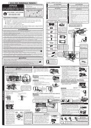
FOR SERVICE PERSONNEL ONLY<br />
HFC<br />
R410A<br />
SAFETY PRECAUTION<br />
Outdoor Unit<br />
RAC-X10CZ<br />
● Carefully read through the procedures of proper<br />
<strong>installation</strong> be<strong>for</strong>e starting <strong>installation</strong> work.<br />
● The sales agent should in<strong>for</strong>m customers regarding<br />
the correct operation of <strong>installation</strong>.<br />
Tools Needed For Installation Work<br />
( mark is tool exclusive use <strong>for</strong> R410A)<br />
● + – Screwdriver ● Measuring Tape ● Knife ● Saw<br />
● Pipe Cutter ● Hexagonal Wrench Key ( 4mm)<br />
● Power Drill (ø 65mm ~ ø 80mm) ● Vacuum Pump<br />
● Pliers or Wrench ● Torque Wrench Vacuum Pump<br />
Adaptor Flare Tool Gas Leakage Detector<br />
Manifold Valve Charge Hose<br />
Read the safety precautions carefully be<strong>for</strong>e operating the <strong>unit</strong>.<br />
The contents of this section are vital to ensure safety. Please pay special attention to the following sign.<br />
! WARNING ........ Incorrect methods of <strong>installation</strong> may cause death or serious injury.<br />
! CAUTION ......... Improper <strong>installation</strong> may result in serious consequence.<br />
Be sure that the <strong>unit</strong> operates in proper condition after <strong>installation</strong>. Explain to customer the proper way of operating<br />
the <strong>unit</strong> as described in the user’s guide.<br />
This <strong>air</strong> <strong>conditioner</strong> uses new refrigerant HFC (R410A).<br />
The basic <strong>installation</strong> work procedures are the same as conventional refrigerant (R22) models.<br />
However, pay careful attention to the following points:<br />
(1) Since the working pressure is 1.6 times higher than that of conventional refrigerant (R22) models, some of the piping and <strong>installation</strong> and <strong>service</strong> tools are special.<br />
Especially, when replacing a conventional refrigerant (R22) model with a new refrigerant R410A model, always replace the conventional piping and flare nuts with the<br />
R410A piping and flare nuts.<br />
(2) Models that use refrigerant R410A have a different charging port thread diameter to prevent erroneous charging with conventional refrigerant (R22) and <strong>for</strong> safety. There<strong>for</strong>e,<br />
check be<strong>for</strong>ehand. [The charging port thread diameter <strong>for</strong> R410A is 1/2 UNF 20 threads per inch.]<br />
(3) Be more careful that <strong>for</strong>eign matter (oil, water, etc.) does not enter the piping than with refrigerant (R22) models. Also, when storing the piping, securely seal the<br />
openings by pinching, taping, etc.<br />
(4) When charging the refrigerant, take into account the slight change in the composition of the gas and liquid phases, and always charge from the liquid phase side whose<br />
composition is stable.<br />
!<br />
WARNING<br />
Please request your sales agent or qualified technician to install your <strong>unit</strong>. Water leakage, short circuit or fire may occur if you do the <strong>installation</strong> work yourself.<br />
Please observe the instructions stated in the <strong>installation</strong> <strong>manual</strong> during the process of <strong>installation</strong>. Improper <strong>installation</strong> may cause water leakage, electric shock and<br />
fire.<br />
Make sure that the <strong>unit</strong>s are mounted at locations which are able to provide full support to the weight of the <strong>unit</strong>s. If not, the <strong>unit</strong>s may collapse and impose danger.<br />
Observe the rules and regulations of the electrical <strong>installation</strong> and the methods described in the <strong>installation</strong> <strong>manual</strong> when dealing with the electrical work. Use power<br />
cables approved by the authorities of your country.<br />
Be sure to use the specified wire <strong>for</strong> connecting the indoor and outdoor <strong>unit</strong>s. Please ensure that the connections are tight after the conductors of the wire are inserted<br />
into the terminals. Improper insertion and loose contact may cause over-heating and fire.<br />
Please use the specified components <strong>for</strong> <strong>installation</strong> work. Otherwise, the <strong>unit</strong>s may collapse or water leakage, electric shock and fire may occur.<br />
Be sure to use the specified piping set <strong>for</strong> R-410A. Otherwise, this may result in broken copper pipes or faults.<br />
When installing or removing an <strong>air</strong> <strong>conditioner</strong>, only specified refrigerant (R410A) shall be allowed, do not allow <strong>air</strong> or moisture to remain in the refrigeration cycle.<br />
Otherwise, pressure in the refrigeration cycle may become abnormally high so that a rupture may be caused.<br />
Be sure to ventilate fully if a refrigerant gas leak while at work. If the refrigerant gas comes into contact with fire, a poisonous gas may occur.<br />
After completion of <strong>installation</strong> work, check to make sure that there is no refrigeration gas leakage. If the refrigerant gas leaks into the room, coming into contact with<br />
fire in the fan-driven heater, space heater, etc., a poisonous gas may occur.<br />
Unauthorized modifications to the <strong>air</strong> <strong>conditioner</strong> may be dangerous. If a breakdown occurs please call a qualified <strong>air</strong> <strong>conditioner</strong> technician or electrician. Improper<br />
rep<strong>air</strong>s may result in water leakage, electric shock and fire, etc.<br />
! CAUTION<br />
A circuit breaker or fuse (16A time delay) must be installed. Without a circuit breaker or fuse the danger of electric shock exists.<br />
A main switch with a contact gap of more than 3mm has to be installed in the power supply line to the outdoor <strong>unit</strong>.<br />
Do not install the <strong>unit</strong> near a location where there is flammable gas. The outdoor <strong>unit</strong> may catch fire if flammable gas leaks around it.<br />
Please ensure smooth flow of water when installing the drain hose.<br />
Piping shall be suitable supported with a maximum spacing of 1m between the supports.<br />
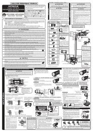
THE CHOICE OF MOUNTING SITE (Please note the following matters and obtain permission from customer be<strong>for</strong>e <strong>installation</strong>).<br />
! WARNING<br />
! WARNING<br />
INDOOR UNIT<br />
● The <strong>unit</strong> should be mounted at stable, non-vibratory location which<br />
can provide full support to the <strong>unit</strong>.<br />
!<br />
CAUTION<br />
● No nearby heat source and no obstruction near the <strong>air</strong> outlet is<br />
allowed.<br />
● The clearance distances from top, right and left are specified in<br />
figure below.<br />
● The location must be convenient <strong>for</strong> water drainage and pipe<br />
connection with the Outdoor <strong>unit</strong>.<br />
● To avoid interference from noise please place the <strong>unit</strong> and its<br />
remote controller at least 1m from the radio, television and inverter<br />
type fluorescent lamp.<br />
● To avoid any error in signal transmission from the remote controller,<br />
please put the controller far away from high-frequency machines<br />
and high-power wireless systems.<br />
● The <strong>installation</strong> height of indoor <strong>unit</strong> must be 2.3m or more.<br />
Names of Indoor Components<br />
No.<br />
Hanger<br />
Item<br />
Qty<br />
1 1<br />
Screw <strong>for</strong> Hanger<br />
2<br />
(4.1x32)<br />
6<br />
Holder <strong>for</strong> Remote<br />
Controller<br />
3 1<br />
AAA Size Battery<br />
4 2<br />
Screw <strong>for</strong> holder of<br />
5<br />
Remote Controller<br />
(3.1x16)<br />
2<br />
6<br />
7<br />
Remote Controller<br />
Purifying Filter<br />
Hole cover sticker<br />
8 1<br />
1<br />
1<br />
Direction of Piping<br />
Connection<br />
Horizontally<br />
perpendicular<br />
to the <strong>unit</strong><br />
There are 4 directions<br />
allowed, namely, horizontally<br />
perpendicular to the <strong>unit</strong>,<br />
vertically down from right,<br />
horizontally out from right and<br />
horizontally out to left.<br />
Don’t <strong>for</strong>m the piping<br />
downward at the left of the <strong>unit</strong>.<br />
Dimension of Mounting Stand<br />
of the Outdoor <strong>unit</strong><br />
(<strong>unit</strong> : mm)<br />
45<br />
mounting stand<br />
30<br />
16<br />
12<br />
30<br />
500 102<br />
20<br />
above 100mm<br />
282 9<br />
300<br />
above 700mm<br />
OUTDOOR UNIT<br />
about 300mm<br />
above 200mm<br />
above 50mm when<br />
installed on the<br />
( )<br />
ceiling of balcony<br />
● The Outdoor <strong>unit</strong> must be mounted at a location which can support<br />
heavy weight. Otherwise, noise and vibration will increase.<br />
! CAUTION<br />
● Do not expose the <strong>unit</strong> under direct sunshine or rain. Besides,<br />
ventilation must be good and clear of obstruction.<br />
● The <strong>air</strong> blown out of the <strong>unit</strong> should not point directly to animals<br />
or plants.<br />
● The clearances of the <strong>unit</strong> from top, left, right and front are specified<br />
in figure below. At least 3 of the above sides must be open <strong>air</strong>.<br />
● Be sure that the hot <strong>air</strong> blown out of the <strong>unit</strong> and noise do not<br />
disturb the neighbourhood.<br />
● Do not install at a location where there is flammable gas, steam,<br />
oil and smoke.<br />
● The location must be convenient <strong>for</strong> water drainage.<br />
● Place the Outdoor <strong>unit</strong> and its connecting cord at least 1m away<br />
from the antenna or signal line of television, radio or telephone.<br />
This is to avoid noise interference.<br />
● Do not install outdoor <strong>unit</strong> facing strong wind direction. It may<br />
damage the fan motor.<br />
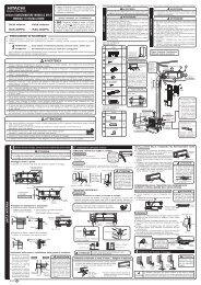
Figure showing the Installation<br />
of Indoor and Outdoor Unit.<br />
Be sure to<br />
completely<br />
seal any<br />
gap with<br />
putty.<br />
about 400mm<br />
must not bend<br />
! CAUTION<br />
In case the pipe length is more than<br />
8m, add refrigerant R410A at 15 gram<br />
per every meter exceeds. However,<br />
pipe length shall not exceed 20m.<br />
Maximum pipe length 20m<br />
Minimum pipe length 4m<br />
above 100mm<br />
Plug<br />
above 50mm<br />
3<br />
5<br />
above 100mm<br />
give clearance as<br />
wide as possible<br />
above 200mm<br />
1<br />
2,300mm or more<br />
4<br />
! CAUTION<br />
• The <strong>installation</strong> height<br />
of indoor <strong>unit</strong> must be<br />
2.3m or more.<br />
6<br />
2<br />
above 100mm<br />
The indoor piping should be<br />
insulated with the enclosed<br />
insulation pipe. (If the<br />
insulator is insufficient,<br />
please use commersial<br />
products).<br />
● The difference in height<br />
between the indoor and<br />
outdoor <strong>unit</strong> should be<br />
kept max 10m.<br />
● The connecting pipe, no<br />
matter big or small,<br />
should all be insulated<br />
with insulation pipe and<br />
then wrapped with vinyl<br />
tape. (The insulator will<br />
deteriorate if it is not<br />
wrapped with tape).<br />
The connection of insulated<br />
drain hose.<br />
inner diameter ø 16mm<br />
Please use insulated drain<br />
hose <strong>for</strong> the indoor piping<br />
(commercial product).<br />
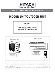
INDOOR UNIT<br />
1<br />
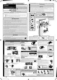
Installation of Hanger, Wall Penetration and Installation of Protection Pipe<br />
!<br />
CAUTION<br />
● The draining of the water container inside the indoor <strong>unit</strong> can be done from the left.<br />
There<strong>for</strong>e the hanger must be fixed horizontally or slightly tilted towards the side of<br />
drain hose. Otherwise, condensed water may overflow the water container.<br />
Direct Mounting On The Wall<br />
● Please use hidden beams in the wall to hold the hanger.<br />
Procedures of Installation and Precautions<br />
● Procedures to fix the hanger.<br />
1.Drill holes on wall. 2. Push plug into the holes. 3. Fix the hanger on wall<br />
(As shown below) (As shown below) with 4.1 x 32 screw<br />
(As shown in figure below)<br />
ø4.8mm<br />
Wall<br />
● Procedures to fix the holder of remote control.<br />
1.Drill holes on wall. 2. Push plug into the holes.<br />
(As shown below) (As shown below)<br />
Wall<br />
ø4.4mm<br />
45mm<br />
60mm<br />
Wall Penetration and Installation of Protection Pipe<br />
● Drill a ø 65mm hole on<br />
wall which is slightly tilted<br />
towards the outdoor side.<br />
Drill the wall at a small<br />
angle.<br />
● Cut the protection pipe<br />
according to the wall<br />
thickness.<br />
● Empty gap in the sleeve<br />
of protection pipe should<br />
be completely sealed<br />
with putty to avoid<br />
dripping of rain water into<br />
the room.<br />
<br />
32mm<br />
20mm<br />
125mm<br />
1 Hanger<br />
2 Screw<br />
3<br />
200mm<br />
Wall<br />
Remote<br />
Control<br />
Holder<br />
Indoor<br />
Seal with<br />
putty<br />
Protection<br />
pipe<br />
80mm<br />
Screw <strong>for</strong> Hanger<br />
Please use more<br />
than 4 screws.<br />
780mm<br />
WALL<br />
Mark<br />
Plug<br />
Plug<br />
5 Screw<br />
Outdoor<br />
2 ~ 5mm<br />
Seal with<br />
putty<br />
Sleeve of<br />
protection<br />
pipe<br />
280mm<br />
above 50mm<br />
125mm<br />
45mm<br />
115mm<br />
450mm<br />
Line<br />
Weight<br />
4.1 x 32 Screw<br />
Level<br />
Ceiling<br />
! WARNING<br />
Hanger<br />
Hole <strong>for</strong> pipe<br />
Be sure that the wire is not<br />
in contact with any metal<br />
in the wall. Please use the<br />
protection pipe as wire<br />
passing through the hollow<br />
part of the wall so as to<br />
prevent the possibility of<br />
damaged by mouse.<br />
Unless it seals completely,<br />
any <strong>air</strong> with high humidity<br />
flows from outdoor and<br />
any dew may drop.<br />
2 Installation of the Indoor Unit<br />
VERTICALLY DOWNWARD PIPING<br />
Preparation<br />
● Connect connecting cord.<br />
● Pull out the pipe, connecting cord and drain hose.<br />
Connecting cords, pipe and<br />
Installation<br />
drain hose must be laid<br />
together with Vinyl tape.<br />
● The upper part of the Indoor <strong>unit</strong> is hanged on the hanger.<br />
● The projection at the lower part of the Indoor <strong>unit</strong> is hooked onto the hanger.<br />
Hanger<br />
HORIZONTAL PIPING<br />
Preparation<br />
Refrigerating<br />
Pipe<br />
Protection<br />
Pipe Drain Hose Connecting<br />
Cord<br />
Lift the body<br />
of the <strong>unit</strong><br />
upwards and<br />
then <strong>for</strong>ce it<br />
downwards.<br />
Hanger<br />
Change of Drain Hose and Installation Procedures.<br />
! CAUTION<br />
Please pull the lower part of<br />
the Indoor <strong>unit</strong> outwards to<br />
check if the <strong>unit</strong> is hooked<br />
onto the hanger. Improper<br />
<strong>installation</strong> may cause<br />
vibration and noise.<br />
● Exchange the location of drain hose and drain cap during horizontal piping as shown in<br />
figure below. Be sure to plug in the drain hose until the insulating material folds upon itself.<br />
● Please use pliers to pull out the drain cap.<br />
(This is an easier way to remove the drain cap).<br />
Drain cap<br />
Please insert<br />
until here<br />
Drain cap<br />
2<br />
1<br />
Projection<br />
Drain hose<br />
[Push] mark positions<br />
! CAUTION Condensed water may leak out if not inserted properly.<br />
HORIZONTAL & DOWNWARD PIPING – MAKING OPENINGS<br />
● During horizontal or downward piping, use a knife to cut<br />
openings as shown in figure. Then smoothen the edges of<br />
openings with a file.<br />
Pipe<br />
support<br />
HOW TO REMOVE INDOOR UNIT<br />
● Push up the (PUSH) sections at the<br />
bottom of the indoor <strong>unit</strong> and pull the<br />
bottom plate towards you. Then the<br />
claws are released from the stationary<br />
plate.<br />
(The (PUSH) sections are indicated by<br />
2 arrows in the right figure)<br />
Pull up the pipe after<br />
bending downward<br />
Drain hose<br />
Please insert<br />
until here<br />
Openings<br />
● Turn the piping while holding down the lower<br />
portion of pipe-support by hand.<br />
INSTALLATION OF REFRIGERATING PIPES AFTER CONNECTION<br />
● The refrigerating pipes should be adjusted to fit into<br />
the hole on the wall and then ready <strong>for</strong> further<br />
connection.<br />
● The terminals of 2 connected pipes must be covered<br />
with insulator used <strong>for</strong> terminal connection. Then the<br />
pipes are wrapped with insulation pipe.<br />
● Connect the connecting cord after removing electrical<br />
cover. (Refer to “CONNECTION OF POWER CORD”)<br />
● After adjustment, fit the connecting cord and pipes<br />
into the space available under the indoor <strong>unit</strong>. Use<br />
holder to hold them tight.<br />
●<br />
Holder can be attached at the either of 2 places.<br />
Please select the easier position.<br />
! CAUTION<br />
● The rubber strap used <strong>for</strong><br />
fixing the insulator should<br />
not be tied with great <strong>for</strong>ce.<br />
Otherwise, this will damage<br />
heat insulation and causes<br />
water condensation.<br />
THE CONNECTION OF REFRIGERATING PIPE DURING THE<br />
INSTALLATION OF INDOOR UNIT<br />
Preparation To Install Refrigerating Pipes ! CAUTION<br />
● The refrigerating pipes and connecting cord<br />
trans<strong>for</strong>m and are attached.<br />
● The end of the refrigerating pipes are at locations<br />
marked with “ ” symbol.<br />
3<br />
Installation<br />
Hang the Indoor <strong>unit</strong> onto the hanger. Use the temporary stand<br />
at the back of the Indoor <strong>unit</strong> to push its lower part 15cm<br />
<strong>for</strong>wards.<br />
● Place the drain hose through the hole on the wall.<br />
● Wrap the refrigerating pipes with insulation pipe after<br />
connecting refrigerating pipe.<br />
● Connect the connecting cord after removing electrical cover.<br />
(Refer to “Connection of Power Cord”)<br />
● After adjustment, the connecting cord and refrigerating pipes<br />
are placed into the space available under the Indoor <strong>unit</strong>.<br />
● The projection of Indoor <strong>unit</strong> must hook to the hanger.<br />
!<br />
CAUTION<br />
Insulation pipe (must be wrapped with<br />
vinyl tape at every 120mm).<br />
Heat insulation pipe<br />
Refrigerating pipe<br />
0.85m<br />
Connecting<br />
cord<br />
Pull this to the front<br />
during the connection<br />
of refrigerating pipes<br />
to ease task.<br />
Installation of Drain Hose<br />
Bending<br />
upwards<br />
Condensed<br />
water pond<br />
Ditch<br />
● Please fix in the plastic core<br />
after flaring to avoid plastic<br />
chips entering the pipes.<br />
! CAUTION<br />
Be sure that the<br />
drain hose is not<br />
loosely connected<br />
or bend.<br />
You are free to choose the side (left or right) <strong>for</strong> the <strong>installation</strong> of drain<br />
hose. Please ensure the smooth flow of condensed water of the Indoor<br />
<strong>unit</strong> during <strong>installation</strong>. (Carelessness may result in water leakage.)<br />
Pipe<br />
Please bend at a small<br />
radius to <strong>for</strong>m an arc<br />
Protection pipe<br />
Condensed<br />
water pond<br />
Drain hose<br />
Connecting cord<br />
Pipe<br />
Drain hose<br />
Connecting<br />
cord<br />
Rubber strap tied with great <strong>for</strong>ce<br />
Projection<br />
Holder<br />
below<br />
5mm<br />
about 15cm<br />
Hook<br />
Connected<br />
section<br />
(EN1) INS RAS-X10CZ 1<br />
18/12/09, 9:29
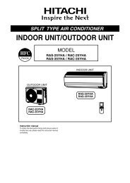
OUTDOOR UNIT<br />
● Please mount the outdoor <strong>unit</strong> on stable ground to prevent vibration<br />
and increase of noise level.<br />
● Decide the location <strong>for</strong> piping after sorting out the different types of<br />
pipe available.<br />
● Open the side plate by unscrewing the screws as shown below.<br />
Please face this side<br />
(suction side) of the <strong>unit</strong> to<br />
the wall.<br />
Please remove side cover<br />
when connecting the<br />
connecting cord.<br />
INSTALLATION OF REFRIGERATING PIPES AND AIR REMOVAL<br />
1<br />
Preparation of Pipe<br />
● Use a pipe cutter to cut the copper pipe.<br />
● Jagged edge will cause leakage.<br />
● Point the side to be trimmed downwards during trimming to prevent copper<br />
chips from entering the pipe.<br />
● Be<strong>for</strong>e flaring, please put on the flare nut.<br />
2<br />
!<br />
Wrench<br />
Die<br />
Outer<br />
Diameter (mm)<br />
6.35 (1/4)<br />
9.52 (3/8)<br />
12.70 (1/2)<br />
15.88 (5/8)<br />
Pipe Connection<br />
CAUTION<br />
!<br />
Copper pipe<br />
CAUTION<br />
Die<br />
A<br />
Copper pipe<br />
Trimming tool<br />
● Recommend to use<br />
R410A flaring tool.<br />
A (mm)<br />
Flare tool <strong>for</strong> R410A Conventional flare tool<br />
Clutch type Clutch type Wing nut type<br />
0.0 ~ 0.5<br />
0.0 ~ 0.5<br />
0.0 ~ 0.5<br />
0.0 ~ 0.5<br />
1.0~1.5<br />
1.0~1.5<br />
1.0~1.5<br />
1.0~1.5<br />
1.5~2.0<br />
1.5~2.0<br />
1.5~2.5<br />
1.5~2.5<br />
In case of removing flare nut of an Indoor <strong>unit</strong>, first remove a nut<br />
of small diameter side, or a seal cap of big diameter side will fly<br />
out. Prevent water from entering into the piping when working.<br />
Flare nut<br />
Thickness<br />
(mm)<br />
Torque<br />
wrench<br />
0.8<br />
0.8<br />
0.8<br />
1.0<br />
Small dia. side<br />
Large dia. side<br />
Valve<br />
head cap<br />
Valve core cap<br />
Small dia. side<br />
Large dia. side<br />
Outer<br />
dia.of pipe<br />
6.35 (1/4")<br />
9.52 (3/8")<br />
12.7 (1/2")<br />
6.35 (1/4")<br />
9.52 (3/8")<br />
12.7 (1/2")<br />
Torque N·m<br />
(kgf · cm)<br />
13.7 – 18.6 (140 – 190)<br />
34.3 – 44.1 (350 – 450)<br />
44.1 – 53.9 (450 – 550)<br />
19.6 – 24.5 (200 ~ 250)<br />
19.6 – 24.5 (200 ~ 250)<br />
29.4 – 34.3 (300 – 350)<br />
12.3 – 15.7 (125 ~ 160)<br />
3<br />
AIR REMOVAL<br />
Removal Of Air From The Pipe And Gas Leakage Inspection<br />
1<br />
2<br />
3<br />
4<br />
Procedures of using Vacuum Pump <strong>for</strong> Air Removal<br />
As shown in right figure, remove the cap<br />
of valve core. Then, connect the charge<br />
hose. Remove the cap of valve head.<br />
Connect the vacuum pump adapter to<br />
the vacuum pump and connect the<br />
charge hose to the adapter.<br />
Fully tighten the “Hi” shuttle of the<br />
manifold valve and completely unscrew<br />
the “Lo” shuttle. Run the vacuum pump<br />
<strong>for</strong> about 10–15 minutes, then completely<br />
tighten the “Lo” shuttle and switch off<br />
the vacuum pump.<br />
Completely unscrew the spindle of the<br />
<strong>service</strong> valve (at 2 places) in anticlockwise<br />
direction to allow the flow of<br />
refrigerant (using Hexagonal Wrench<br />
key).<br />
Remove the charge hose and tighten the<br />
cap of valve head. Check the cap’s<br />
periphery if there is any gas leakage.<br />
The task is then completed.<br />
Gas Leakage Inspection<br />
Please use gas leakage detector to check if leakage<br />
occurs at the connection of Flare nut as shown on<br />
the right.<br />
If gas leakage occurs, further tighten the connection<br />
to stop leakage. (Use the detector provided <strong>for</strong><br />
R410A)<br />
When the meter reaches - 101KPa<br />
(-76cmHg) during pumping, fully<br />
tighten the shuttle.<br />
Meter showing pressure<br />
Closed<br />
Charge hose<br />
Valve<br />
Lo<br />
Valve<br />
Vacuum pump<br />
adapter<br />
R410A<br />
Manifold valve<br />
Vacuum<br />
pump<br />
When pumping starts, slightly loosen the<br />
flare nut to check of <strong>air</strong> sucked in. Then<br />
tighten the flare nut.<br />
Cap of valve head<br />
Hi<br />
The body of<br />
<strong>service</strong> valve<br />
Cap of<br />
valve core<br />
Hexagonal<br />
Wrench Key<br />
Cap of valve head<br />
!<br />
WARNING<br />
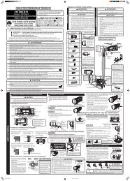
Procedures of Wiring<br />
● THIS APPLIANCE MUST<br />
BE EARTHED.<br />
Power supply shall be connected at the rated voltage, otherwise<br />
the <strong>unit</strong> will be broken or could not reach the specified capacity.<br />
Wiring Of The Indoor Unit<br />
● For wire connection of the Indoor <strong>unit</strong>, you need to remove Low Cover and Indicator Cover.<br />
1<br />
2<br />
3<br />
● Pull the cover at 1 and 2 in<br />
the directions as shown by<br />
arrows to remove the low<br />
cover.<br />
Indoor Unit<br />
Outdoor Unit<br />
TEMPORARY<br />
SWITCH<br />
TEMPORARY<br />
SWITCH<br />
C D<br />
1.6 or<br />
2.0<br />
L N C D<br />
Indicator<br />
Cover<br />
Screw<br />
Low cover<br />
CONNECTION OF POWER CORD<br />
Outdoor Unit<br />
Connecting Cord<br />
Strip wires<br />
25mm 25mm<br />
10mm<br />
10mm<br />
GRN + 10mm<br />
YEL 35mm<br />
Power line<br />
Control line<br />
Detail of cutting the connecting cord<br />
Connecting Cord<br />
2.0<br />
AC 220 - 240V<br />
Indoor Unit<br />
30mm<br />
10mm<br />
10mm<br />
70mm<br />
GRN + YEL<br />
Strip wires<br />
When removing the connecting wires <strong>for</strong> the Indoor <strong>unit</strong>,<br />
please remove the low cover panel in front of the <strong>unit</strong>.<br />
!<br />
WARNING<br />
● The naked part of the wire core should be 10 mm and<br />
fix it to the terminal tightly. Then try to pull the individual<br />
wire to check if the contact is tight. Improper insertion<br />
may burn the terminal.<br />
● Be sure to use only power cables approved from the<br />
authorities in your country. For example in Germany:<br />
Cable type: NYM 3x1.5mm 2 (Fuse = 16A time delay).<br />
● Please refer to the <strong>installation</strong> <strong>manual</strong> <strong>for</strong> wire connection<br />
to the terminals of the <strong>unit</strong>s. The cabling must meet the<br />
standards of electrical <strong>installation</strong>.<br />
● There is a AC voltage of 220-240V between the L and<br />
N terminals. There<strong>for</strong>e, be<strong>for</strong>e servicing, be sure to<br />
remove the plug from the AC outlet or switch off the<br />
main switch.<br />
● Do not make any connection in the middle of the<br />
connecting cable. It may cause the wire over heated,<br />
emit smoke and fire.<br />
TEMPORARY<br />
SWITCH<br />
Attach Indicator Cover and tightened screw<br />
(do not tightened too hard as the screw hole<br />
at front cover might be broken)<br />
7<br />
TEMPORARY<br />
SWITCH<br />
5<br />
Remove Screw and Indicator Cover<br />
Attach back Low Cover<br />
Wiring of The Outdoor Unit<br />
● Please remove the side plate <strong>for</strong> wire connection.<br />
!<br />
WARNING<br />
● If you cannot attach the side<br />
plate due to the connecting<br />
cord, please press the<br />
connecting cord in direction<br />
to the front panel to fix it.<br />
● Be sure that the hooks of the<br />
side plate is fixed in certainly.<br />
Otherwise water leakage may<br />
occur and this causes short<br />
circuit or faults.<br />
4<br />
!<br />
WARNING<br />
● Investigate the power supply capacity and other<br />
electrical conditions at the <strong>installation</strong> location.<br />
Depending on the model of room <strong>air</strong> <strong>conditioner</strong><br />
to be installed, request the customer to make<br />
arrangements <strong>for</strong> the necessary electrical work<br />
etc.<br />
The electrical work includes the wiring work up<br />
the outlet. In localities where electrical<br />
conditions are poor, use of a voltage regulation<br />
is recommended.<br />
● Install outlet <strong>for</strong> the room <strong>air</strong> <strong>conditioner</strong> within<br />
the reaching range of the line cord.<br />
IMPORTANT<br />
D<br />
C<br />
● Please fix back the electrical<br />
plate after wiring work is<br />
complete. Otherwise if short<br />
circuit occur it may cause<br />
<strong>unit</strong> burn.<br />
Fuse Capacity<br />
16A time delay fuse<br />
After remove the screw and cover,<br />
and put the connecting cords and fix<br />
the cover with screw.<br />
Connect the<br />
earth cord<br />
Earth terminal<br />
LNC D<br />
FINAL STAGE OF INSTALLATION<br />
1<br />
Insulation And Maintenance Of Pipe Connection<br />
● The connected terminals should be completely sealed with<br />
heat insulator and then tied up with rubber strap.<br />
● Please tie the pipe and power line together with vinyl tape as<br />
shown in the figure showing the <strong>installation</strong> of Indoor and<br />
Outdoor <strong>unit</strong>s. Then fix their position with holders.<br />
● To enchance the heat insulation and to prevent water<br />
condensation, please cover the outdoor part of the drain hose<br />
and pipe with insulation pipe.<br />
● Completely seal any gap with putty.<br />
Insulation material <strong>for</strong> pipe connection<br />
3<br />
Sleeve of<br />
protection pipe<br />
Power Source And Operation Test<br />
Power Source<br />
Putty<br />
!<br />
CAUTION<br />
Putty<br />
2<br />
Installation Of Remote Controller<br />
● The remote controller can be placed in its holder which is<br />
fixed on wall or beam.<br />
● To operate the remote controller at its holder, please ensure<br />
that the <strong>unit</strong> can receive signal transmitted from the controller<br />
at the place where the holder is to be fixed. The <strong>unit</strong> will beep<br />
when signal is received from the remote controller. The signal<br />
transmission is weaken by the fluorescent light. There<strong>for</strong>e,<br />
during the <strong>installation</strong> of the remote control holder, please<br />
switch on the light, even during day time, to determine the<br />
mounting location of the holder.<br />
The controller should be<br />
insert from top into<br />
bottom side of the holder<br />
as shown in figure below.<br />
Remote<br />
Controller<br />
Screw (2 pieces)<br />
Holder <strong>for</strong><br />
Remote Controller<br />
Pump Down Method When Reuse<br />
Existing Piping (R22 Model) <strong>for</strong><br />
R410A Model<br />
● Compressor oil of R22 model is insoluble in compressor<br />
oil of R410A model. The mixing of compressor oil may<br />
cause damage of compressor.<br />
Possibility of Mixing<br />
● Reuse of piping of R22 model is dangerous because of its<br />
compressor oil.<br />
● When reuse piping of R22 model, pump down must be<br />
carried out properly to ensure compressor oil which is<br />
remained inside piping is collected away.<br />
!<br />
CAUTION<br />
Reuse of piping R-22 model only apply if previous model<br />
is Hitachi and proper pump down method is used.<br />
To Reuse Old Piping<br />
● Piping of R22 model can be reused only when <strong>air</strong><strong>conditioner</strong><br />
is properly pumped down.<br />
● The purpose of pump down is to collect back the<br />
compressor oil (which is mixed with refrigerant and<br />
circulating inside refrigeration cycle) properly into the<br />
outdoor <strong>unit</strong> of <strong>air</strong> <strong>conditioner</strong>.<br />
Proper Pump Down Method<br />
1 Operate <strong>air</strong> <strong>conditioner</strong> 2 After 10~15 minutes of pre<br />
at cooling mode <strong>for</strong><br />
operation, close 2s valve.<br />
10~15 minutes. After 3 minutes, close 4s valve.<br />
Most Important Process<br />
Purpose: To make the oil &<br />
refrigerant mix together.<br />
They are in separated<br />
condition when<br />
<strong>air</strong> <strong>conditioner</strong> is<br />
stopped.<br />
Mixed<br />
refrigerant & oil<br />
will be collected<br />
into outdoor<br />
<strong>unit</strong>.<br />
3 Take out <strong>air</strong> <strong>conditioner</strong> 4 Install New Refrigerant <strong>air</strong><br />
<strong>unit</strong>.<br />
<strong>conditioner</strong><br />
It is advisable to flush the<br />
piping with R410A to avoid<br />
any contamination remain<br />
be<strong>for</strong>e new <strong>installation</strong>.<br />
● Please use a new socket. Accident may occur due to the use<br />
of old socket because of poor contact.<br />
● Please plug in and then remove the plug <strong>for</strong> 2 – 3 times. This<br />
is to ensure that the plug is completely plugged into the socket.<br />
● Keep additional length <strong>for</strong> the power cord and do not render<br />
the plug under external <strong>for</strong>ce as this may cause poor contact.<br />
● Do not fix the power cord with U-shape nail.<br />
Operation Test<br />
● Please ensure that the <strong>air</strong> <strong>conditioner</strong> is in normal operating<br />
condition during the operation test.<br />
● Explain to your customer the proper operation procedures<br />
as described in the user’s <strong>manual</strong>.<br />
<br />
(EN2) INS RAS-X10CZ 1<br />
18/12/09, 9:30
9<br />
HITACHI<br />
●<br />
●<br />
●<br />
●<br />
●<br />
●<br />
●<br />
●<br />
●<br />
●<br />
●<br />
●<br />
●<br />
●<br />
●<br />
●<br />
●<br />
●<br />
UNTUK KEGUNAAN JURUTEKNIK SAHAJA<br />
RISALAH PANDUAN PEMASANGAN<br />
PENGHAWA DINGIN BILIK<br />
Unit dalam bilik<br />
RAS-X10CZ<br />
HFC<br />
R410A<br />
Unit luar bilik<br />
RAC-X10CZ<br />
● Sila baca dengan teliti cara-cara pemasangan sebelum<br />
melakukan kerja-kerja pemasangan.<br />
● Wakil jualan harus memberi keterangan mengenai cara<br />
pengendalian kepada pelanggan mengikut arahan<br />
pengendalian.<br />
Alat-alat diperlukan untuk kerja pemasangan<br />
( adalah simbol bagi alat yang khusus untuk R410A.)<br />
● + – Pemutar skru ● Pita pengukur ● Pisau ● Gergaji<br />
● Pemotong paip ● Kunci Alen ( 4mm) ● Gerudi elektrik<br />
(ø 65mm ~ ø 80mm) ● Pam vakum ● Playar atau spana<br />
● Sepana kilas Adaptor Pam Vakum Flare tool Pengesan<br />
Kebocoran Gas Injap Pancarongga Hos Pengecas<br />
PERKARA YANG PERLU DIAMBIL PERHATIAN UNTUK KESELAMATAN<br />
Sebelum menggunakan mesin, sila telitikan “perkara-perkara yang perlu diambil perhatian untuk keselamatan” bagi mengendalikan mesin dengan betul.<br />
Perkara-perkara yang dicatatkan di bahagian ini mengandungi isi-isi penting berkenaan dengan keselamatan, oleh itu mesti mengambil perhatian terhadap perkara di<br />
bahagian ini.<br />
! AMARAN ........ Pemasangan yang salah mungkin boleh mengakibatkan kematian atau kecederaan yang serius<br />
! PERHATIAN .... Pemasangan yang salah boleh mendatangkan akibat yang teruk.<br />
Setelah kerja-kerja pemasangan siap, pastikan penyaman udara beroperasi dengan baik. Terangkan secara teliti kepada pelanggan mengenai cara pengendalian<br />
mengikut arahan pengendalian.<br />
Penghawa dingin ini menggunakan bahan penyejuk HFC (R410A)<br />
Asas prosedur-prosedur kerja pemasangan adalah sama seperti model-model bahan penyejuk (R22) yang konvensional. Walaubagaimana pun, perkara-perkara yang berikut perlu<br />
diambil perhatian:<br />
(1) Memandangkan tekanan kerja adalah 1.6 kali lebih tinggi daripada model-model bahan penyejuk (R22) yang konvensional, terdapat sesetengah paip serta peralatan pemasangan<br />
dan servis yang khas.<br />
Khususnya apabila menukar model bahan penyejuk (R22) yang konvensional dengan model bahan penyejuk R410A yang baru, paip konventional dan nat kembang (flare nut)<br />
hendaklah diganti dengan paip dan nat kembang (flare nut) R410A.<br />
(2) Model-model yang menggunakan bahan penyejuk R410A mempunyai diameter ulir liang pengecasan yang berbeza bagi mengelakkan kerosakan serta untuk keselamatan<br />
semasa mengecas dengan bahan penyejuk (R22) yang konventional. Oleh itu, pastikan dahulu. (Diameter ulir liang pengecasan bagi R410A adalah 1/2 UNF 20 ulir setiap inci.)<br />
(3) Hati-hati agar benda-benda asing (minyak, <strong>air</strong> dan lain-lain) tidak masuk ke dalam paip bagi model bahan penyejuk (R22). Semasa menyimpan paip, tutup bukaan paip.<br />
(4) Semasa mengecas bahan penyejuk, perhatikan perubahan komposisi gas dan fasa cec<strong>air</strong>. Cas daripada bahagian fasa cec<strong>air</strong> yang komposisinya stabil.<br />
!<br />
!<br />
AMARAN<br />
Minta wakil jualan atau juruteknik untuk melakukan kerja pemasangan. Kerja pemasangan yang dilakukan sendiri mungkin akan menyebabkan kebocoran <strong>air</strong>, kejutan elektrik dan kebakaran.<br />
Sila lakukan kerja pemasangan mengikut risalah panduan pemasangan.<br />
Pemasangan yang tidak sempurna mungkin akan menyebabkan kebocoran <strong>air</strong>, kejutan elektrik dan kebakaran.<br />
Semasa pemasangan, pastikan <strong>unit</strong>-<strong>unit</strong> dipasang pada tempat yang dapat menampung beratnya. Kalau tidak, <strong>unit</strong>-<strong>unit</strong> mungkin akan jatuh ke bawah.<br />
Patuhi peraturan-peraturan mengenai pemasangan elektrik dan kaedah-kaedah yang dihuraikan dalam <strong>manual</strong> pemasangan apabila melakukan kerja-kerja elektrik. Gunakan kabel kuasa<br />
yang diluluskan oleh pihak berkuasa negara anda.<br />
Penyambungan antara <strong>unit</strong> luar bilik dan <strong>unit</strong> dalam bilik mesti menggunakan kabel penyambung yang ditetapkan. Setelah dawai dicacahkan ke dalam terminal, pastikan cacahan itu adalah<br />
kukuh.<br />
Pemasangan yang tidak kukuh dan tidak sempurna boleh membawa kesan pemanasan dan kebakaran.<br />
Alat-alat yang diperlukan untuk kerja pemasangan mesti adalah alat-alat yang ditetapkan.<br />
Jika tidak, mungkin akan mengakibatkan <strong>unit</strong> terhempas, kebocoran <strong>air</strong>, kejutan elektrik dan kebakaran.<br />
Pastikan anda mengguna set pempaipan yang telah ditetapkan untuk R410. Kalau tidak, ini mungkin akan menyebabkan kepecahan paip tembaga atau keretakan.<br />
Semasa memasang atau menanggalkan penyaman udara, hanya bahan penyejuk (R410A) yang dibolehkan. Jangan biarkan udara atau kelembapan kekal di dalam pengitar (cycle) bahan<br />
penyejuk. Ini kerana tekanan di dalam pengitar (cycle) bahan penyejuk akan menjadi terlalu tinggi dan kerosakan boleh berlaku.<br />
Pastikan pengudaraan yang sepenuhnya sekiranya berlaku kebocoran gas pendingin semasa melakukan kerja. Jika gas pendingin menyentuhi api, suatu gas beracun mungkin dikeluarkan.<br />
Selepas kerja pemasangan disempurnakan, periksa untuk memastikan bahawa tidak ada sebarang kebocoran gas pendingin. Jika gas pendingin itu bocor dan memasuki bilik, dan<br />
menyentuhi api pada alat pemanas yang dipacu kipas, pemanas ruang, dan lain-lain, maka suatu gas beracun mungkin dikeluarkan.<br />
Pengubahsuaian yang tidak dibenarkan kepada alat penyaman udara mungkin berbahaya. Jika kerosakan berlaku, sila hubungi juruteknik atau juruelektrik yang bertauliah dalam bidang<br />
alat penyaman udara. Pembaikan yang tidak wajar mungkin akan menyebabkan kebocoran <strong>air</strong>, kejutan elektrik bahkan kebakaran, dan lain-lain.<br />
PERHATIAN<br />
Satu pemutus litar atau fius (masa tunda 16A) mesti dipasangkan. Tanpa pemutus litar atau fius mungkin wujud bahaya kejutan elektrik. Satu suis utama dengan jurang sentuhan yang<br />
melebihi 3mm hendaklah dipasangkan dalam saluran bekalan kuasa kepada <strong>unit</strong> diluar rumah.<br />
Jangan pasang di tempat yang terdapat gas mudah terbakar kerana mungkin berlaku kebakaran jika gas terbocor di sekitar <strong>unit</strong> luar bilik.<br />
Semasa memasang salur <strong>air</strong>, pastikan <strong>air</strong> dapat mengalir keluar dengan mudah.<br />
Pempaipan hendaklah sesuai dan disokong oleh peruangan maksimum 1m di antara penyokong-penyokong.<br />
PEMILIHAN UNTUK TEMPAT PEMASANGAN (Sila ambil perhatian dan dapatkan kebenaran pelanggan terlebih dahulu).<br />
! AMARAN<br />
! AMARAN<br />
UNIT DALAM BILIK<br />
Alat-alat tambahan berserta dengan <strong>unit</strong> dalam bilik<br />
No.<br />
Nama alat<br />
Plat pemasangan<br />
Bil.<br />
1 1<br />
Skru plat pemasangan<br />
2 6<br />
(4.1x32)<br />
Pemegang alat kawalan<br />
jauh<br />
3 1<br />
Bateri AAA saiz<br />
4 2<br />
Skru pemegang alat<br />
5<br />
kawalan jauh<br />
(3.1x16)<br />
2<br />
6<br />
7<br />
8<br />
● Unit ini mesti dipasang pada tempat yang dapat memberi<br />
sokongan, tidak bergetar dan kukuh.<br />
Alat kawalan jauh<br />
Pembersih penapis<br />
udara<br />
!<br />
PERHATIAN<br />
● Tiada sumber haba yang berhampiran dan tiada halangan di<br />
hadapan lubang udara keluar.<br />
● Di atas, kiri dan kanan <strong>unit</strong> ini mesti meninggalkan ruangan<br />
mengikut ukuran tanda seperti dalam gambarajah di bawah.<br />
● Dipasangkan di tempat yang mudah menyalurkan <strong>air</strong> dan dapat<br />
bersambung dengan paip <strong>unit</strong> luar bilik.<br />
● Untuk mengelakkan gangguan isyarat, sila pasangkan <strong>unit</strong> ini<br />
dan alat kawalan jauh berjarak lebih dari 1m televisyen dan radio.<br />
● Untuk mengelakkan berlaku kesilapan pada alat kawalan jauh,<br />
sila jauhkan alat kawalan jauh dari alat yang menghasilkan<br />
gelombang elektromagnet atau alat pemancar gelombang.<br />
● Tinggi <strong>unit</strong> dalam haruslah lebih dari 2.3m.<br />
Pelekat lubang skru<br />
1<br />
1<br />
1<br />
Arah paip ditarik keluar<br />
Terdapat 4 arah paip ditarik<br />
keluar iaitu lurus ke belakang,<br />
ke kanan dan ke bawah,<br />
melintang ke kanan.<br />
Jangan bentukkan paip kearah<br />
bawah di kiri <strong>unit</strong>.<br />
Ukuran tapak <strong>unit</strong> luar bilik<br />
(<strong>unit</strong> : mm)<br />
tapak <strong>unit</strong><br />
Penyambungan<br />
12<br />
30<br />
500 102<br />
Ditarik keluar<br />
secara<br />
melintang dari<br />
belakang<br />
45<br />
30<br />
16<br />
20<br />
282 9<br />
300<br />
UNIT LUAR BILIK<br />
● Unit luar bilik mesti dipasang di tempat yang boleh menampung<br />
beratnya, kalau tidak bunyi <strong>unit</strong> dan getaran mungkin bertambah kuat.<br />
! PERHATIAN<br />
● Jangan pasang di tempat yang terdedah kepada <strong>air</strong> hujan dan pancaran cahaya<br />
matahari. Tempat itu perlu mempunyai pengaliran udara yang baik.<br />
● Jangan biarkan lubang udara keluar menghadap haiwan atau tumbuhan.<br />
● Di bahagian atas, kiri, kanan, depan dan belakang mesti meninggalkan ruangan<br />
mengikut ukuran tanda seperti dalam gambarajah di bawah, dan mesti<br />
mempunyai sekurang-kurangnya tiga sisi yang terbuka.<br />
● Jangan biarkan udara yang ditiup keluar dan bunyi <strong>unit</strong> mengganggu jiran.<br />
● Di larang memasang di tempat yang terdapat gas mudah terbakar, wap <strong>air</strong> dan<br />
asap minyak.<br />
● Di tempat yang mudah untuk penyaluran <strong>air</strong>.<br />
● Semasa memasang <strong>unit</strong> luar bilik dan kabel penyambung, jauhkan dari kabel aerial,<br />
kabel isyarat dan kabel bekalan kuasa bagi televisyen, radio dan telefon dengan<br />
jarak sekurang-kurangnya 1m. Ini adalah untuk mengelakkan gangguan isyarat lain.<br />
● Jangan pasang <strong>unit</strong> luar di luar bangunan yang terdedah kearah angin yang kuat.<br />
Ini mungkin akan merosakkan motor kipas.<br />
Ilustrasi pemasangan <strong>unit</strong><br />
dalam bilik dan <strong>unit</strong> luar bilik<br />
! PERHATIAN<br />
• Jika panjang paip melebihi 8m,<br />
tambahkan refrigeran R410A sebanyak<br />
15 gram pada setiap tambahan 1<br />
meter. Walaubagaimanapun panjang<br />
paip tidak boleh melebihi 20m.<br />
Sumbatkan<br />
liang-liang<br />
dengan<br />
gam<br />
penampal<br />
! PERHATIAN<br />
• Tinggi <strong>unit</strong> dalam bilik<br />
haruslah lebih dari<br />
2.3m.<br />
Sila balut paip <strong>unit</strong> dalaman<br />
dengan salur penebat yang<br />
diberikan, (jika salur<br />
penebat tidak cukup,<br />
gunakan bahan servis).<br />
● Jarak tegak antara <strong>unit</strong><br />
dalam bilik dan <strong>unit</strong> luar<br />
bilik tidak melebihi 10 m.<br />
● Paip kecil dan paip besar<br />
juga perlu dibalut dengan<br />
bahan penebat,<br />
kemudian dibalut dengan<br />
tape getah di luarnya.<br />
Jika tidak dibalut dengan<br />
tape getah, bahan<br />
penebat akan menjadi<br />
lapuk dengan cepat.<br />
Penyambungan salur <strong>air</strong><br />
yang bertebat.<br />
Sila gunakan salur <strong>air</strong><br />
bertebat (bahan servis)<br />
untuk paip melintang yang<br />
lalu ke dalam bilik.<br />
UNIT DALAM BILIK<br />
1<br />
Memasang plat pemasangan, menebuk lubang dan memasang salur pelindung<br />
! PERHATIAN<br />
● Bekas <strong>air</strong> terkondensasi <strong>unit</strong> dalaman adalah dipasang di sebelah kiri. Oleh itu, plat<br />
pemasangan mesti dipasang selari dengan aras <strong>air</strong> atau senget sedikit ke sebelah<br />
salur <strong>air</strong>. Kalau tidak, <strong>air</strong> terkondesasi mungkin akan mengalir keluar.<br />
Kawasan dinding yang sesuai untuk pemasangan<br />
● Sila pasangkan plat pemasangan pada tiang dalam dinding.<br />
45mm<br />
60mm<br />
125mm<br />
Prosedur pemasangan dan perkara yang perlu diambil perhatian<br />
● Prosedur memasang plat pemasangan pada dinding.<br />
1.Tebuk lubang pada 2. Masukkan pasak 3. Menggunakan skru 4.1 x 32<br />
dinding. (Seperti penyangkut. (Seperti untuk memakukan plat<br />
gambarah di bawah) gambarajah di bawah) pemasangan pada dinding.<br />
(Seperti gambarajah di bawah)<br />
● Prosedur memasang pemegang alat kawalan jauh pada dinding.<br />
1.Tebuk lubang pada 2. Masukkan pasak penyangkut.<br />
dinding. (Seperti<br />
(Seperti gambarajah di bawah)<br />
gambarajah di bawah)<br />
Menebuk lubang pada dinding dan pemasangan salur pelindung<br />
Sebelah<br />
Sebelah<br />
! PERHATIAN 3<br />
dalam dinding luar dinding<br />
! PERHATIAN Air terkondensasi mungkin mengalir keluar jika salur <strong>air</strong> ditekan.<br />
● Semasa menebuk lubang<br />
ø 65 mm, condongkan ke<br />
bawah sedikit di sebelah<br />
dinding luar, kekalkan<br />
kecondongan ini.<br />
● Keratkan salur pelindung<br />
mengikut ketebalan<br />
dinding.<br />
● Liang-liang pada penutup<br />
paip hendaklah disumbat<br />
dengan gam penampal<br />
untuk mengelakkan <strong>air</strong><br />
masuk ke dalam bilik.<br />
200mm<br />
80mm<br />
780mm<br />
Skru untuk<br />
plat pemasangan<br />
Gunakan lebih<br />
dari 4 skru.<br />
Sumbat dengan<br />
gam penampal<br />
Salur<br />
pelindung<br />
Penanda<br />
DINDING<br />
2 ~ 5mm<br />
Sumbat dengan<br />
gam penampal<br />
Penutup paip<br />
280mm<br />
125mm<br />
45mm<br />
115mm<br />
450mm<br />
Garisan<br />
Pemberat<br />
Alat aras <strong>air</strong><br />
Lubang<br />
untuk paip<br />
Plat<br />
pemasangan<br />
Semasa memasang kabel<br />
penyambung, jangan bersentuhan<br />
dengan palang logam dalam<br />
dinding. Jika kabel penyambung<br />
melalui dinding yang kosong di<br />
bahagian tengahnya, terdapat<br />
kemungkinan kabel digigit oleh tikus<br />
dan mendatangkan bahaya. Oleh itu<br />
mesti menggunakan salur<br />
pelindung.<br />
Sekiranya tidak dimaterikan<br />
sepenuhnya, sebarang udara yang<br />
mempunyai kelembapan tinggi akan<br />
mengalir masuk dari luar rumah dan<br />
embun akan menitis.<br />
2 Pemasangan <strong>unit</strong> dalam bilik<br />
Pemasangan paip secara lurus atau ke bawah<br />
Persediaan memasang<br />
● Sambungkan kabel kuasa.<br />
● Keluarkan paip, kabel kuasa dan salur <strong>air</strong>.<br />
Pemasangan<br />
● Bahagian atas <strong>unit</strong> dalam bilik mesti digantung pada plat<br />
pemasangan.<br />
● Bahagian yang tertonjol di bawah <strong>unit</strong> dalam bilik pula<br />
perlu bersangkut pada pencangkuk plat pemasangan.<br />
Plat pemasangan<br />
Pelindung<br />
Paip<br />
Paip penyejuk<br />
Salur <strong>air</strong><br />
Kabel kuasa<br />
Angkat <strong>unit</strong><br />
ke atas dan<br />
kemudian<br />
tekankan ke<br />
bawah.<br />
CARA MENGELUARKAN UNIT DALAM BILIK<br />
● Tolak bahagian (PUSH) ke atas di<br />
bawah <strong>unit</strong> dalam bilik dan tarik plat di<br />
bawah ke arah anda, kemudian sepit<br />
akan keluar dari plat pemasangan.<br />
(Bahagian (PUSH) ditandakan dengan<br />
2 anak panah dalam gambarajah di<br />
sebelah kanan)<br />
Penutup<br />
Sila tekankan<br />
hingga garisan ini<br />
Penutup<br />
2<br />
1<br />
Plat<br />
pemasangan<br />
Bahagian tertonjol<br />
Salur <strong>air</strong><br />
arah tanda [Push]<br />
SEMASA MEMASANG PAIP SECARA MELINTANG<br />
Persediaan Memasang<br />
Salur <strong>air</strong><br />
Kabel kuasa, paip<br />
dan salur <strong>air</strong> mestilah<br />
diikat dengan tape.<br />
Sila tekankan<br />
hingga garisan ini<br />
MEMBUAT BUKAAN SEMASA MEMASANG PAIP SECARA MELINTANG DAN KE BAWAH<br />
Pemegang<br />
paip<br />
Perubahan kedudukan<br />
selepas dibengkok<br />
ke bawah<br />
!<br />
PERHATIAN<br />
Sila tarik bahagian bawah<br />
<strong>unit</strong> dengan tangan untuk<br />
memastikan pencangkuk<br />
plat pemasangan telah<br />
bersangkut dengan<br />
bahagian tertonjol <strong>unit</strong>.<br />
Pemasangan yang tidak<br />
sempurna akan<br />
menyebabkan <strong>unit</strong> dalam<br />
bilik bergegar dan<br />
mengeluarkan bunyi bising.<br />
Kerja penukaran dan pemasangan salur <strong>air</strong><br />
● Semasa memasang paip secara melintang, salur <strong>air</strong> dan penutup lubang <strong>air</strong> ditukar<br />
dan dipasang seperti gambarajah di bawah. Selain itu, pastikan salur <strong>air</strong> dimasukkan<br />
sehingga bahagian penebat haba yang bonjol.<br />
● Sila pusing dan tarik penutup lubang <strong>air</strong> dengan playar<br />
(cara ini lebih mudah untuk keluarkan penutup).<br />
● Semasa memasang paip secara melintang ataupun lurus<br />
ke bawah, sila buat bukaan di bahagian bawah dengan<br />
pisau, kemudian kemaskan dengan kikir.<br />
Bukaan<br />
● Ubah kedudukan paip dengan memegang<br />
bahagian bawah pemegang paip dengan<br />
tangan.<br />
MEMASANG PAIP PENYEJUK SELEPAS PENYAMBUNGAN<br />
● Pembentukan dan penyambungan paip agen penyejuk<br />
dilakukan mengikut kedudukan lubang pada dinding.<br />
● Bahagian sambungan paip harus dibalut dengan bahan<br />
penebat haba, kemudian dibaluti lagi dengan salur penebat.<br />
● Sambungkan dawai penyambung selepas menanggalkan<br />
penutup elektrik. (Rujuk kepada “PENYAMBUNGAN DAWAI<br />
KUASA”)<br />
● Selepas menyambung kabel penyambung dan membentuk<br />
paip, masukkan ke dalam ruangan bawah <strong>unit</strong> dalam bilik.<br />
Gunakan pemegang untuk memegangnya dengan rapat.<br />
Salut penebat (diikat dengan tape<br />
setiap 120mm).<br />
● Pemegang boleh disangkut pada salah satu daripada 2<br />
tempat. Sila pilih tempat yang lebih mudah.<br />
0.85m<br />
Pemasangan<br />
Bengkokkan keatas<br />
!<br />
PERHATIAN<br />
Takungan <strong>air</strong><br />
Takungan<br />
Bengkokkan sedikit<br />
Pelindung paip<br />
Salur <strong>air</strong><br />
Takungan<br />
<strong>air</strong><br />
!<br />
!<br />
Paip<br />
Paip<br />
Bahagian<br />
tertonjol<br />
Kabel kuasa<br />
Pemegang<br />
Salur <strong>air</strong><br />
Kabel kuasa<br />
PERHATIAN<br />
● Pengikatan bahan penebat yang<br />
terlalu ketat oleh tape boleh<br />
mengurangkan kesan penebatan<br />
haba dan menyebabkan<br />
pembentukan wap. Oleh itu<br />
jangan ikat dengan terlalu ketat.<br />
Tape getah diikat dengan kuat<br />
PENYAMBUNGAN PAIP SEMASA MEMASANG UNIT DALAM BILIK<br />
Pemasangan paip agen penyejuk<br />
● Paip-paip pendingin dan dawai penyambung<br />
pengubah ada dikepilkan.<br />
● Penghujung paip-paip pendingin terletak di<br />
lokasi-lokasi yang bertanda dengan<br />
lambang “ ”.<br />
Gantungkan <strong>unit</strong> dalam bilik pada plat pemasangan. Gunakan penyokong di<br />
belakang <strong>unit</strong> dalam bilik untuk menahan ke hadapan sejauh kira-kira 15cm.<br />
● Masukkan salur <strong>air</strong> ke dalam lubang dinding.<br />
● Balutkan paip-paip pendingin bersama paip penebatan selepas<br />
menyambungkan paip pendingin.<br />
● Sambungkan dawai penyambung selepas menanggalkan penutup elektrik.<br />
(Rujuk kepada “Penyambungan Dawai Kuasa”).<br />
● Selepas melakukan penyelarasan, dawai penyambung dan paip-paip<br />
pendingin hendaklah diletakkan ke dalam ruang yang boleh didapati di bawah<br />
<strong>unit</strong> dalam rumah. Gunakan pemegang untuk memegangnya dengan ketat.<br />
● Bahagian tertonjol di bawah <strong>unit</strong> dalam bilik hendaklah bersangkut dengan<br />
pencangkuk plat pemasangan.<br />
Salur penebat<br />
Paip penyejuk<br />
Kabel<br />
kuasa<br />
Tarikkan paip ke<br />
depan sedikit untuk<br />
memudahkan kerja<br />
penyambungan.<br />
Kepastian penyaluran <strong>air</strong><br />
PERHATIAN<br />
● Jika menggunakan tiub plastik,<br />
pastikan anda masukkannya<br />
selepas melakukan pengembangan<br />
paip untuk mengelakkan serpihan<br />
masuk ke dalam paip.<br />
5mm<br />
ke bawah<br />
anggaran 15cm<br />
Penyangkuk<br />
Penyambungan<br />
! PERHATIAN<br />
Pastikan salur <strong>air</strong><br />
tidak tercabut<br />
atau terbengkok.<br />
Semasa pemasangan <strong>unit</strong> dalam bilik anda boleh memilih kedudukan pemasangan<br />
salur <strong>air</strong> (kiri atau kanan), oleh itu pastikan pengaliran <strong>air</strong> terkondensasi adalah<br />
tiada masalah. (Kecuaian dalam hal ini boleh membawa kepada penitisan <strong>air</strong>).<br />
<br />
(BM1) INS RAS-X10CZ 1<br />
18/12/09, 9:31
UNIT LUAR BILIK<br />
● Sila pasang di tempat yang kukuh untuk mengelakkan<br />
getaran dan penghasilan bunyi yang kuat.<br />
● Semua paip disusun, kemudian tentukan kedudukan<br />
masing-masing.<br />
● Buka panel sisi dengan membuka skru seperti rajah di<br />
bawah.<br />
Bahagian ini (bahagian penyedut)<br />
dipasang menghadap ke dinding<br />
Keluarkan penutup untuk<br />
kerja penyambungan wayar<br />
PENGURUSAN DAN PENYAMBUNGAN PAIP SERTA PROSES PENYINGKIRAN UDARA<br />
1<br />
2<br />
!<br />
Spana<br />
Penyediaan paip<br />
● Gunakan alat pemotong paip untuk memotong paip tembaga.<br />
Acuan<br />
Penyambungan Paip<br />
PERHATIAN<br />
Puting<br />
heksagon<br />
Paip tembaga<br />
!<br />
Acuan<br />
A<br />
Paip tembaga<br />
Pemulas<br />
● Disyorkan agar<br />
menggunakan alat<br />
R410A flaring tool.<br />
Jika menanggalkan “flare nut” daripada sebuah <strong>unit</strong> dalam rumah, mula-mula<br />
tanggalkan nat yang sisinya berdiameter kecil, kalau tidak tudung penyumbat<br />
yang sisinya berdiameter besar akan meloncat keluar. Cegahkan <strong>air</strong> daripada<br />
memasuki ke dalam pempaipan semasa menjalankan kerja.<br />
Soket<br />
Spana<br />
kilas<br />
PERHATIAN<br />
● Pemotongan tidak sekata boleh menghasilkan kebocoran gas.<br />
● Semasa pemotongan, paip tembaga harus dihala ke bawah untuk mengelakkan<br />
serpihan masuk ke dalam paip.<br />
● Sila pasangkan soket dahulu sebelum melakukan proses pengembangan paip.<br />
Diameter<br />
Luar (mm)<br />
6.35 (1/4)<br />
9.52 (3/8)<br />
12.70 (1/2)<br />
15.88 (5/8)<br />
Ketebalan<br />
(mm)<br />
0.8<br />
0.8<br />
0.8<br />
1.0<br />
A (mm)<br />
Flare tool untuk R410A Flare tool original<br />
Jenis ketatan Jenis ketatan Jenis soket<br />
0.0 ~ 0.5<br />
0.0 ~ 0.5<br />
0.0 ~ 0.5<br />
0.0 ~ 0.5<br />
1.0~1.5<br />
1.0~1.5<br />
1.0~1.5<br />
1.0~1.5<br />
1.5~2.0<br />
1.5~2.0<br />
1.5~2.5<br />
1.5~2.5<br />
Diameter<br />
luar paip (ø)<br />
Garis pusat paip halus 6.35 (1/4")<br />
Garis pusat paip besar 9.52 (3/8")<br />
12.7 (1/2")<br />
Garis pusat paip halus 6.35 (1/4")<br />
Palam<br />
Garis pusat paip besar<br />
kepala injap<br />
9.52 (3/8")<br />
12.7 (1/2")<br />
Palam pusat injap<br />
Daya memutar N.m<br />
[kgf • cm]<br />
13.7 – 18.6 (140 – 190)<br />
34.3 – 44.1 (350 – 450)<br />
44.1 – 53.9 (450 – 550)<br />
19.6 – 24.5 (200 ~ 250)<br />
19.6 – 24.5 (200 ~ 250)<br />
29.4 – 34.3 (300 – 350)<br />
12.3 – 15.7 (125 ~ 160)<br />
3<br />
PENYINGKIRAN UDARA<br />
Penyingkiran Udara dari paip dan pemeriksaan kebocoran<br />
1<br />
2<br />
3<br />
4<br />
Cara menggunakan pam vakum<br />
Seperti yang ditunjukkan dalam rajah di<br />
sebelah kanan, tanggalkan tudung pada<br />
teras injap. Kemudian, sambungkan hos<br />
cas. Tanggalkan tudung di kepala injap.<br />
Sambungkan adaptor pam vakum<br />
kepada pam vakum dan kemudian<br />
sambungkan hos cas kepada adaptor.<br />
Tutupkan butang “Hi” sepenuhnya<br />
manakala butang “Lo” dibuka<br />
sepenuhnya, biarkan pam vakum<br />
berfungsi selama 10 ~ 15 minit,<br />
kemudian bukakan butang “Lo”<br />
sepenuhnya, hentikan pam vakum.<br />
Putarkan nat injap servis (terdapat 2 nat)<br />
mengikut arah lawan jam sehingga<br />
maksimum untuk membenarkan gas<br />
penyejuk mengalir (gunakan Kunci<br />
Allen).<br />
Tanggalkan hos cas dan ketatkan tudung<br />
kepala injap. Periksa sekitaran tudung<br />
itu untuk memastikan tidak ada sebarang<br />
kebocoran gas. Setelah itu tugas ini<br />
dianggap sempurna.<br />
Pemeriksaan kebocoran gas<br />
Gambarajah di sebelah kanan menunjukkan<br />
penggunaan alat penguji kebocoran untuk memastikan<br />
sama ada terdapat agen penyejuk terbocor keluar dari<br />
bahagian sambungan soket atau tidak.<br />
Jika terdapat kebocoran, sila ketatkan lagi sambungan<br />
untuk menghalang kebocoran. (Gunakan pengesan<br />
(detector) yang khas untuk R410A)<br />
Semasa pemvakuman, tutupkan<br />
sepenuhnya butang apabila meter<br />
tekanan menunjuk —101KPa (—76cmHg)<br />
Meter tekanan<br />
Lo Hi<br />
Paip<br />
Injap<br />
pengisi<br />
Injap<br />
Adaptor Pam<br />
vakum<br />
Tutup<br />
Injap servis<br />
Injap pembahagi<br />
Pam vakum<br />
Semasa pemvakuman dimulakan, tolong<br />
longgarkan sedikit soket untuk memastikan<br />
udara disedut ke dalam, kemudian<br />
ketatkan semula soket.<br />
Palam<br />
pusat injap<br />
Kunci Allen<br />
Palam kepala injap Palam kepala injap<br />
!<br />
AMARAN<br />
Bekalan kuasa hendaklah disambungkan pada kadar voltan yang<br />
telah ditetapkan. Jika tidak, kerosakan boleh berlaku pada <strong>unit</strong> atau<br />
ia tidak akan dapat mencapai kapasiti yang ditetapkan.<br />
Cara menyambungkan kabel penyambung<br />
Unit Dalam Bilik<br />
● UNIT INI MESTI DIBUMIKAN.<br />
Unit Luar Bilik<br />
Cara penyambungan <strong>unit</strong> dalam bilik<br />
● Bagi penyambungan wayar <strong>unit</strong> dalam rumah, anda perlu membuka Penutup Bawah dan Penutup Penunjuk.<br />
1<br />
TEMPORARY<br />
SWITCH<br />
2<br />
TEMPORARY<br />
SWITCH<br />
3<br />
● Tarik penutup pada 1 dan 2<br />
mengikut arah anak panah bagi<br />
membuka Penutup Bawah.<br />
PENYAMBUNGAN KABEL PENYAMBUNG<br />
Unit Luar Bilik<br />
HIJAU +<br />
KUNING<br />
C D<br />
1.6 atau<br />
2.0<br />
Dawai Penyambung<br />
Kabel Tanpa Penebat<br />
25mm 25mm<br />
10mm<br />
10mm<br />
10mm<br />
35mm<br />
Talian bekalan kuasa<br />
Talian kontrol<br />
Cara memotong kabel penyambung<br />
!<br />
L N C D<br />
AMARAN<br />
Dawai Penyambung<br />
AC 220 - 240V<br />
Unit Dalam Bilik<br />
30mm<br />
10mm<br />
● Bahagian teras dawai yang terdedah hendaklah berukuran<br />
10mm dan dipasang dengan ketat kepada terminal.<br />
Kemudian cuba menarik setiap satu dawai untuk<br />
memastikan bahawa sambungan itu cukup kuat.<br />
Penyisipan yang tidak baik mungkin akan membakar<br />
terminal itu.<br />
● Pastikan bahawa anda menggunakan hanya kabel-kabel<br />
kuasa yang diluluskan oleh pihak berkuasa di negara anda.<br />
Contohnya di negeri Jerman: Jenis kabel NYM 3x1.5mm 2 ,<br />
(fius = masa tunda 16A)<br />
● Sila rujuk kepada Manual Pemasangan untuk<br />
penyambungan dawai ke terminal-terminal <strong>unit</strong> itu.<br />
Pengkabelan mestilah mematuhi piawaian pemasangan<br />
elektrik.<br />
● Terdapat voltan AC yang mempunyai kuasa 220-240V di<br />
antara terminal L dan N. Oleh itu, sebelum melakukan<br />
servis, pastikan anda mencabut palam daripada saluran<br />
keluar AC ataupun matikan suis utama.<br />
● Jangan buat sambungan pada pertengahan kabel<br />
penyambungan. Ini boleh menyebabkan wayar menjadi<br />
panas, berasap dan terbakar.<br />
2.0<br />
10mm<br />
70mm<br />
HIJAU + KUNING<br />
Kabel Tanpa Penebat<br />
Semasa hendak mengeluarkan kabel penyambung <strong>unit</strong> dalam<br />
bilik, sila tanggalkan penutup hiasan di depannya dahulu.<br />
7<br />
Penutup<br />
Penunjuk<br />
TEMPORARY<br />
SWITCH<br />
Skru<br />
TEMPORARY<br />
SWITCH<br />
Pasang Penutup Penunjuk dan pasangkan<br />
skru (jangan pasang dengan tekanan yang<br />
kuat kerana berkemungkinan lubang skru<br />
akan pecah).<br />
Lekatkan pelekat lubang<br />
skru 8 (disediakan di<br />
dalam aksesori) dengan<br />
cermat untuk menutup skru.<br />
Penutup<br />
Bawah<br />
5<br />
Buka Skru dan Penutup Penunjuk<br />
Pasang semula Penutup Bawah<br />
Cara penyambungan <strong>unit</strong> luar bilik<br />
● Sila buka plat di sisi bagi penyambungan wayar.<br />
!<br />
PERHATIAN<br />
● Jika anda tidak dapat melekatkan plat<br />
di sisi oleh kerana dawai penyambung,<br />
tekan dawai penyambung ke arah<br />
panel hadapan untuk memasangnya.<br />
● Pastikan bahawa cangkuk-cangkuk<br />
pada plat di sisi terpasang dengan<br />
rapi. Jika tidak, kebocoran <strong>air</strong> mungkin<br />
berlaku dan ini mungkin menyebabkan<br />
kejadian litar pintas atau kegagalan.<br />
4<br />
!<br />
PERHATIAN<br />
● Pastikan penutup diskru semula selepas<br />
kerja penyambungan selesai.<br />
● Periksa bekalan kuasa dan segala<br />
keadaan barangan elektrik sebelum<br />
pemasangan.<br />
Bergantung kepada <strong>unit</strong> penghawa<br />
dingin yang dipasang, minta kebenaran<br />
pemasangan dari pelanggan sebelum<br />
pendawaian dilakukan.<br />
Di kawasan di mana bekalan elektrik<br />
tidak stabil, penggunaan “voltage<br />
regulation” diperlukan.<br />
● Laluan keluar bagi penyaman udara<br />
hendaklah dipasangkan pada jarak yang<br />
boleh dicapai oleh talian dawai.<br />
PENTING<br />
Kapasiti fius<br />
Fius masa tunda 16A<br />
D<br />
C<br />
Pastikan memasang kabel<br />
penyambung dengan skru, selepas<br />
mengeluarkan skru dan penutup.<br />
Sambungan<br />
ke wayar bumi<br />
Terminal Bumi<br />
L N C D<br />
PENGEMASAN TERAKHIR<br />
1<br />
Penebatan dan kemasan pada bahagian sambungan paip<br />
● Bahagian sambungan paip hendaklah disaluti dengan bahan<br />
penebat haba, kemudian dibalut dengan tape getah.<br />
● Sila ikut cara pemasangan <strong>unit</strong> dalam bilik dan <strong>unit</strong> luar bilik untuk<br />
mengikatkan paip dan kabel penyambung dengan tape getah,<br />
kemudian gunakan pengepit untuk kukuhkan penyambungan.<br />
● Bagi mengelakkan bahagian salur <strong>air</strong> dan paip yang terdedah<br />
menghasilkan titisan <strong>air</strong>, sila balutkan bahagian ini dengan salur<br />
penebat untuk menambahkan lagi kesan penebatan haba.<br />
● Sila sumbatkan liang-liang kecil dengan gam penampal.<br />
Bahan penebat haba<br />
3<br />
Penutup paip<br />
Gam penampal<br />
Gam penampal<br />
Bekalan kuasa elektrik dan Ujian operasi<br />
Bekalan kuasa elektrik<br />
! PERHATIAN<br />
● Sila gunakan plag yang baru. Penggunaan plag yang lama mungkin akan<br />
menyebabkan kemalangan atau kerosakan kerana terdapat kelonggaran.<br />
● Sila tarik dan masukkan plag ke dalam soket 2 – 3 kali supaya plag boleh<br />
masuk ke dalam soket sepenuhnya.<br />
● Tolong lebihkan sedikit kepanjangan kabel untuk mengelakkan tindakan daya<br />
luar ke atas plag serta sentuhan di antara plag dengan soket adalah sempurna.<br />
● Jangan pakukan kabel elektrik dengan paku bentuk U.<br />
2<br />
Pemasangan alat kawalan jauh<br />
● Alat kawalan jauh boleh diletakkan di atas pemegangnya yang<br />
dipasang pada dinding atau tiang.<br />
● Jika anda ingin mengendalikan alat kawalan jauh di atas<br />
pemegangnya, sila pastikan isyaratnya boleh diterima oleh<br />
mesin penyaman udara terlebih dahulu bagi menentukan<br />
kedudukan pemegangnya. Penyaman udara akan<br />
mengeluarkan bunyi “beep” apabila menerima isyarat dari alat<br />
kawalan jauh. Selain itu, cahaya lampu juga boleh<br />
mempengaruhi penerimaan isyarat, oleh itu sila pasangkan<br />
lampu semasa hendak menentukan kedudukan pemegang<br />
walaupun pada siang.<br />
Alat kawalan jauh hendaklah disisipkan daripada atas ke<br />
bawah pemegangnya seperti ditunjukkan dalam gambarajah<br />
di bawah.<br />
Ujian operasi<br />
Alat kawalan jauh<br />
Skru (2 batang)<br />
Pemegang alat<br />
kawalan jauh<br />
● Semasa ujian operasi dilakukan pastikan penghawa dingin<br />
udara dapat berfungsi dengan sempurna.<br />
● Sila beri penerangan yang mudah difahami dan betul kepada<br />
pelanggan mengikut turutan dalam arahan pengendalian.<br />
Kaedah “Pump Down” Apabila Menggunakan Semula<br />
Perpaipan Sedia Ada (R22 Model) untuk Model R410A<br />
● Minyak pemampat model R22 adalah tidak larut dalam minyak<br />
pemampat bagi model R410A. Pencampuran minyak pemampat<br />
boleh menyebabkan kerosakan terhadap pemampat.<br />
Kemungkinan Pencampuran<br />
● Penggunaan semula perpaipan model R22 adalah berbahaya<br />
disebabkan minyak pemampatnya.<br />
● Apabila menggunakan perpaipan bagi model R22, “Pump Down”<br />
mestilah dijalankan dengan betul bagi memastikan minyak<br />
pemampat yang masih berada di dalam perpaipan dikumpulkan<br />
kesemuanya.<br />
! PERHATIAN<br />
Paip model R-22 hanya boleh digunakan sekiranya model lama yang digunakan<br />
adalah Hitachi dan kaedah “Pump Down” dilakukan dengan betul.<br />
Untuk Menggunakan Semula Perpaipan Lama<br />
● Perpaipan model R22 hanya boleh digunakan semula sekiranya<br />
penyaman udara di “Pump Down” dengan betul.<br />
● Tujuan “Pump Down” adalah untuk mengumpulkan semula<br />
minyak pemampat (yang bercampur dengan bahan pendingin<br />
dan berkitar di dalam kitaran pendinginan) dengan betul ke dalam<br />
<strong>unit</strong> luar penyaman udara.<br />
Kaedah “Pump Down” yang Betul<br />
1 Jalankan penyaman udara 2 Selepas 10~15 minit prakendalian,<br />
pada mod pendinginan tutup injap 2 hala.<br />
selama 10~15 minit.<br />
Selepas 3 minit, tutup injap 3 hala.<br />
Proses paling Mustahak<br />
Tujuan: Untuk mencampurkan<br />
minyak & bahan pendingin<br />
supaya sebati. Ia berada dalam<br />
keadaan<br />
terasing apabila<br />
penyaman udara<br />
berhenti.<br />
Bahan pendingin<br />
& minyak<br />
tercampur akan<br />
dikumpulkan ke<br />
dalam <strong>unit</strong> luar.<br />
3 Keluarkan <strong>unit</strong> penyaman 4 Pasang penyaman udara Bahan<br />
udara.<br />
Pendingin Baru.<br />
Adalah dinasihatkan agar<br />
membersihkan paip dengan<br />
menggunakan R410A bagi<br />
mengelakkan sebarang<br />
kontaminasi tertinggal<br />
sebelum memasang<br />
yang baru.<br />
<br />
(BM2) INS RAS-X10CZ 1<br />
18/12/09, 9:31