( ) split unit air conditioner installation manual for service personnel ...
( ) split unit air conditioner installation manual for service personnel ...
( ) split unit air conditioner installation manual for service personnel ...

Create successful ePaper yourself
Turn your PDF publications into a flip-book with our unique Google optimized e-Paper software.
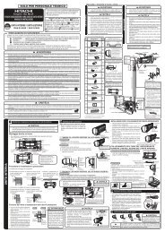
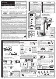
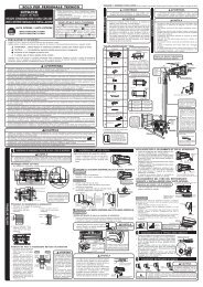
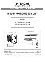
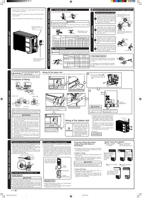
OUTDOOR UNIT<br />
● Please mount the outdoor <strong>unit</strong> on stable ground to prevent vibration<br />
and increase of noise level.<br />
● Decide the location <strong>for</strong> piping after sorting out the different types of<br />
pipe available.<br />
● Open the side plate by unscrewing the screws as shown below.<br />
Please face this side<br />
(suction side) of the <strong>unit</strong> to<br />
the wall.<br />
Please remove side cover<br />
when connecting the<br />
connecting cord.<br />
INSTALLATION OF REFRIGERATING PIPES AND AIR REMOVAL<br />
1<br />
Preparation of Pipe<br />
● Use a pipe cutter to cut the copper pipe.<br />
● Jagged edge will cause leakage.<br />
● Point the side to be trimmed downwards during trimming to prevent copper<br />
chips from entering the pipe.<br />
● Be<strong>for</strong>e flaring, please put on the flare nut.<br />
2<br />
!<br />
Wrench<br />
Die<br />
Outer<br />
Diameter (mm)<br />
6.35 (1/4)<br />
9.52 (3/8)<br />
12.70 (1/2)<br />
15.88 (5/8)<br />
Pipe Connection<br />
CAUTION<br />
!<br />
Copper pipe<br />
CAUTION<br />
Die<br />
A<br />
Copper pipe<br />
Trimming tool<br />
● Recommend to use<br />
R410A flaring tool.<br />
A (mm)<br />
Flare tool <strong>for</strong> R410A Conventional flare tool<br />
Clutch type Clutch type Wing nut type<br />
0.0 ~ 0.5<br />
0.0 ~ 0.5<br />
0.0 ~ 0.5<br />
0.0 ~ 0.5<br />
1.0~1.5<br />
1.0~1.5<br />
1.0~1.5<br />
1.0~1.5<br />
1.5~2.0<br />
1.5~2.0<br />
1.5~2.5<br />
1.5~2.5<br />
In case of removing flare nut of an Indoor <strong>unit</strong>, first remove a nut<br />
of small diameter side, or a seal cap of big diameter side will fly<br />
out. Prevent water from entering into the piping when working.<br />
Flare nut<br />
Thickness<br />
(mm)<br />
Torque<br />
wrench<br />
0.8<br />
0.8<br />
0.8<br />
1.0<br />
Small dia. side<br />
Large dia. side<br />
Valve<br />
head cap<br />
Valve core cap<br />
Small dia. side<br />
Large dia. side<br />
Outer<br />
dia.of pipe<br />
6.35 (1/4")<br />
9.52 (3/8")<br />
12.7 (1/2")<br />
6.35 (1/4")<br />
9.52 (3/8")<br />
12.7 (1/2")<br />
Torque N·m<br />
(kgf · cm)<br />
13.7 – 18.6 (140 – 190)<br />
34.3 – 44.1 (350 – 450)<br />
44.1 – 53.9 (450 – 550)<br />
19.6 – 24.5 (200 ~ 250)<br />
19.6 – 24.5 (200 ~ 250)<br />
29.4 – 34.3 (300 – 350)<br />
12.3 – 15.7 (125 ~ 160)<br />
3<br />
AIR REMOVAL<br />
Removal Of Air From The Pipe And Gas Leakage Inspection<br />
1<br />
2<br />
3<br />
4<br />
Procedures of using Vacuum Pump <strong>for</strong> Air Removal<br />
As shown in right figure, remove the cap<br />
of valve core. Then, connect the charge<br />
hose. Remove the cap of valve head.<br />
Connect the vacuum pump adapter to<br />
the vacuum pump and connect the<br />
charge hose to the adapter.<br />
Fully tighten the “Hi” shuttle of the<br />
manifold valve and completely unscrew<br />
the “Lo” shuttle. Run the vacuum pump<br />
<strong>for</strong> about 10–15 minutes, then completely<br />
tighten the “Lo” shuttle and switch off<br />
the vacuum pump.<br />
Completely unscrew the spindle of the<br />
<strong>service</strong> valve (at 2 places) in anticlockwise<br />
direction to allow the flow of<br />
refrigerant (using Hexagonal Wrench<br />
key).<br />
Remove the charge hose and tighten the<br />
cap of valve head. Check the cap’s<br />
periphery if there is any gas leakage.<br />
The task is then completed.<br />
Gas Leakage Inspection<br />
Please use gas leakage detector to check if leakage<br />
occurs at the connection of Flare nut as shown on<br />
the right.<br />
If gas leakage occurs, further tighten the connection<br />
to stop leakage. (Use the detector provided <strong>for</strong><br />
R410A)<br />
When the meter reaches - 101KPa<br />
(-76cmHg) during pumping, fully<br />
tighten the shuttle.<br />
Meter showing pressure<br />
Closed<br />
Charge hose<br />
Valve<br />
Lo<br />
Valve<br />
Vacuum pump<br />
adapter<br />
R410A<br />
Manifold valve<br />
Vacuum<br />
pump<br />
When pumping starts, slightly loosen the<br />
flare nut to check of <strong>air</strong> sucked in. Then<br />
tighten the flare nut.<br />
Cap of valve head<br />
Hi<br />
The body of<br />
<strong>service</strong> valve<br />
Cap of<br />
valve core<br />
Hexagonal<br />
Wrench Key<br />
Cap of valve head<br />
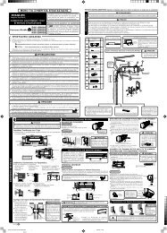
!<br />
WARNING<br />
Procedures of Wiring<br />
● THIS APPLIANCE MUST<br />
BE EARTHED.<br />
Power supply shall be connected at the rated voltage, otherwise<br />
the <strong>unit</strong> will be broken or could not reach the specified capacity.<br />
Wiring Of The Indoor Unit<br />
● For wire connection of the Indoor <strong>unit</strong>, you need to remove Low Cover and Indicator Cover.<br />
1<br />
2<br />
3<br />
● Pull the cover at 1 and 2 in<br />
the directions as shown by<br />
arrows to remove the low<br />
cover.<br />
Indoor Unit<br />
Outdoor Unit<br />
TEMPORARY<br />
SWITCH<br />
TEMPORARY<br />
SWITCH<br />
C D<br />
1.6 or<br />
2.0<br />
L N C D<br />
Indicator<br />
Cover<br />
Screw<br />
Low cover<br />
CONNECTION OF POWER CORD<br />
Outdoor Unit<br />
Connecting Cord<br />
Strip wires<br />
25mm 25mm<br />
10mm<br />
10mm<br />
GRN + 10mm<br />
YEL 35mm<br />
Power line<br />
Control line<br />
Detail of cutting the connecting cord<br />
Connecting Cord<br />
2.0<br />
AC 220 - 240V<br />
Indoor Unit<br />
30mm<br />
10mm<br />
10mm<br />
70mm<br />
GRN + YEL<br />
Strip wires<br />
When removing the connecting wires <strong>for</strong> the Indoor <strong>unit</strong>,<br />
please remove the low cover panel in front of the <strong>unit</strong>.<br />
!<br />
WARNING<br />
● The naked part of the wire core should be 10 mm and<br />
fix it to the terminal tightly. Then try to pull the individual<br />
wire to check if the contact is tight. Improper insertion<br />
may burn the terminal.<br />
● Be sure to use only power cables approved from the<br />
authorities in your country. For example in Germany:<br />
Cable type: NYM 3x1.5mm 2 (Fuse = 16A time delay).<br />
● Please refer to the <strong>installation</strong> <strong>manual</strong> <strong>for</strong> wire connection<br />
to the terminals of the <strong>unit</strong>s. The cabling must meet the<br />
standards of electrical <strong>installation</strong>.<br />
● There is a AC voltage of 220-240V between the L and<br />
N terminals. There<strong>for</strong>e, be<strong>for</strong>e servicing, be sure to<br />
remove the plug from the AC outlet or switch off the<br />
main switch.<br />
● Do not make any connection in the middle of the<br />
connecting cable. It may cause the wire over heated,<br />
emit smoke and fire.<br />
TEMPORARY<br />
SWITCH<br />
Attach Indicator Cover and tightened screw<br />
(do not tightened too hard as the screw hole<br />
at front cover might be broken)<br />
7<br />
TEMPORARY<br />
SWITCH<br />
5<br />
Remove Screw and Indicator Cover<br />
Attach back Low Cover<br />
Wiring of The Outdoor Unit<br />
● Please remove the side plate <strong>for</strong> wire connection.<br />
!<br />
WARNING<br />
● If you cannot attach the side<br />
plate due to the connecting<br />
cord, please press the<br />
connecting cord in direction<br />
to the front panel to fix it.<br />
● Be sure that the hooks of the<br />
side plate is fixed in certainly.<br />
Otherwise water leakage may<br />
occur and this causes short<br />
circuit or faults.<br />
4<br />
!<br />
WARNING<br />
● Investigate the power supply capacity and other<br />
electrical conditions at the <strong>installation</strong> location.<br />
Depending on the model of room <strong>air</strong> <strong>conditioner</strong><br />
to be installed, request the customer to make<br />
arrangements <strong>for</strong> the necessary electrical work<br />
etc.<br />
The electrical work includes the wiring work up<br />
the outlet. In localities where electrical<br />
conditions are poor, use of a voltage regulation<br />
is recommended.<br />
● Install outlet <strong>for</strong> the room <strong>air</strong> <strong>conditioner</strong> within<br />
the reaching range of the line cord.<br />
IMPORTANT<br />
D<br />
C<br />
● Please fix back the electrical<br />
plate after wiring work is<br />
complete. Otherwise if short<br />
circuit occur it may cause<br />
<strong>unit</strong> burn.<br />
Fuse Capacity<br />
16A time delay fuse<br />
After remove the screw and cover,<br />
and put the connecting cords and fix<br />
the cover with screw.<br />
Connect the<br />
earth cord<br />
Earth terminal<br />
LNC D<br />
FINAL STAGE OF INSTALLATION<br />
1<br />
Insulation And Maintenance Of Pipe Connection<br />
● The connected terminals should be completely sealed with<br />
heat insulator and then tied up with rubber strap.<br />
● Please tie the pipe and power line together with vinyl tape as<br />
shown in the figure showing the <strong>installation</strong> of Indoor and<br />
Outdoor <strong>unit</strong>s. Then fix their position with holders.<br />
● To enchance the heat insulation and to prevent water<br />
condensation, please cover the outdoor part of the drain hose<br />
and pipe with insulation pipe.<br />
● Completely seal any gap with putty.<br />
Insulation material <strong>for</strong> pipe connection<br />
3<br />
Sleeve of<br />
protection pipe<br />
Power Source And Operation Test<br />
Power Source<br />
Putty<br />
!<br />
CAUTION<br />
Putty<br />
2<br />
Installation Of Remote Controller<br />
● The remote controller can be placed in its holder which is<br />
fixed on wall or beam.<br />
● To operate the remote controller at its holder, please ensure<br />
that the <strong>unit</strong> can receive signal transmitted from the controller<br />
at the place where the holder is to be fixed. The <strong>unit</strong> will beep<br />
when signal is received from the remote controller. The signal<br />
transmission is weaken by the fluorescent light. There<strong>for</strong>e,<br />
during the <strong>installation</strong> of the remote control holder, please<br />
switch on the light, even during day time, to determine the<br />
mounting location of the holder.<br />
The controller should be<br />
insert from top into<br />
bottom side of the holder<br />
as shown in figure below.<br />
Remote<br />
Controller<br />
Screw (2 pieces)<br />
Holder <strong>for</strong><br />
Remote Controller<br />
Pump Down Method When Reuse<br />
Existing Piping (R22 Model) <strong>for</strong><br />
R410A Model<br />
● Compressor oil of R22 model is insoluble in compressor<br />
oil of R410A model. The mixing of compressor oil may<br />
cause damage of compressor.<br />
Possibility of Mixing<br />
● Reuse of piping of R22 model is dangerous because of its<br />
compressor oil.<br />
● When reuse piping of R22 model, pump down must be<br />
carried out properly to ensure compressor oil which is<br />
remained inside piping is collected away.<br />
!<br />
CAUTION<br />
Reuse of piping R-22 model only apply if previous model<br />
is Hitachi and proper pump down method is used.<br />
To Reuse Old Piping<br />
● Piping of R22 model can be reused only when <strong>air</strong><strong>conditioner</strong><br />
is properly pumped down.<br />
● The purpose of pump down is to collect back the<br />
compressor oil (which is mixed with refrigerant and<br />
circulating inside refrigeration cycle) properly into the<br />
outdoor <strong>unit</strong> of <strong>air</strong> <strong>conditioner</strong>.<br />
Proper Pump Down Method<br />
1 Operate <strong>air</strong> <strong>conditioner</strong> 2 After 10~15 minutes of pre<br />
at cooling mode <strong>for</strong><br />
operation, close 2s valve.<br />
10~15 minutes. After 3 minutes, close 4s valve.<br />
Most Important Process<br />
Purpose: To make the oil &<br />
refrigerant mix together.<br />
They are in separated<br />
condition when<br />
<strong>air</strong> <strong>conditioner</strong> is<br />
stopped.<br />
Mixed<br />
refrigerant & oil<br />
will be collected<br />
into outdoor<br />
<strong>unit</strong>.<br />
3 Take out <strong>air</strong> <strong>conditioner</strong> 4 Install New Refrigerant <strong>air</strong><br />
<strong>unit</strong>.<br />
<strong>conditioner</strong><br />
It is advisable to flush the<br />
piping with R410A to avoid<br />
any contamination remain<br />
be<strong>for</strong>e new <strong>installation</strong>.<br />
● Please use a new socket. Accident may occur due to the use<br />
of old socket because of poor contact.<br />
● Please plug in and then remove the plug <strong>for</strong> 2 – 3 times. This<br />
is to ensure that the plug is completely plugged into the socket.<br />
● Keep additional length <strong>for</strong> the power cord and do not render<br />
the plug under external <strong>for</strong>ce as this may cause poor contact.<br />
● Do not fix the power cord with U-shape nail.<br />
Operation Test<br />
● Please ensure that the <strong>air</strong> <strong>conditioner</strong> is in normal operating<br />
condition during the operation test.<br />
● Explain to your customer the proper operation procedures<br />
as described in the user’s <strong>manual</strong>.<br />
<br />
(EN2) INS RAS-X10CZ 1<br />
18/12/09, 9:30