CA6-95…180 Contactor Instruction sheet - Sprecher + Schuh
CA6-95…180 Contactor Instruction sheet - Sprecher + Schuh
CA6-95…180 Contactor Instruction sheet - Sprecher + Schuh

You also want an ePaper? Increase the reach of your titles
YUMPU automatically turns print PDFs into web optimized ePapers that Google loves.
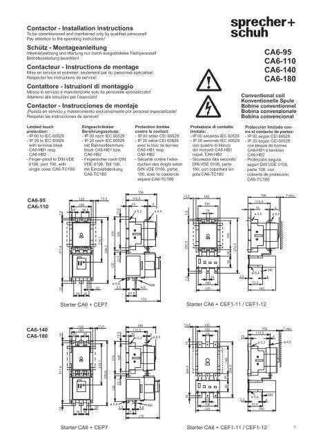
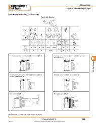
<strong>Contactor</strong> - Installation instructions<br />
To be commissioned and maintained only by qualified personnel!<br />
Pay attention to the operating instructions!<br />
Schütz - Montageanleitung<br />
Inbetriebsetzung und Wartung nur durch ausgebildetes Fachpersonal!<br />
Betriebsanleitung beachten!<br />
Contacteur - <strong>Instruction</strong>s de montage<br />
Mise en service et entretien: seulement par du personnel spécialisé!<br />
Respecter les instructions de service!<br />
Contattore - Istruzioni di montaggio<br />
Messa in servizio e manutenzione solo da personale specializzato!<br />
Attenersi alle istruzioni per l’esercizio!<br />
<strong>Contactor</strong> - Instrucciones de montaje<br />
¡Puesta en servicio y mantenimiento exclusivamente por personal especializado!<br />
Respetar las instrucciones de servicio!<br />
Limited touch<br />
protection:<br />
- IP 00 to IEC 60529<br />
- IP 20 to IEC 60529<br />
with terminal block<br />
<strong>CA6</strong>-HB1 resp.<br />
<strong>CA6</strong>-HB2<br />
- Finger-proof to DIN VDE<br />
0106, part 100, with<br />
single cover <strong>CA6</strong>-TC180<br />
<strong>CA6</strong>-95<br />
<strong>CA6</strong>-110<br />
<strong>CA6</strong>-140<br />
<strong>CA6</strong>-180<br />
7,5<br />
12 311,8<br />
10<br />
317,8<br />
12<br />
120<br />
100<br />
16 38,5<br />
Eingeschränkter<br />
Berührungsschutz:<br />
- IP 00 nach IEC 60529<br />
- IP 20 nach IEC 60529<br />
mit Rahmenklemmenblock<br />
<strong>CA6</strong>-HB1 bzw.<br />
39 39<br />
<strong>CA6</strong>-HB2<br />
- Fingersicher nach DIN<br />
VDE 0106, Teil 100,<br />
mit Einzelabdeckung<br />
<strong>CA6</strong>-TC180<br />
Starter <strong>CA6</strong> + CEP7<br />
120<br />
100<br />
13,5<br />
20 39<br />
39 39<br />
20<br />
216,1<br />
20<br />
216,1<br />
13,5<br />
336,3<br />
339,8<br />
Starter <strong>CA6</strong> + CEP7<br />
Protection limitée<br />
contre le contact:<br />
- IP 00 selon CEI 60529<br />
- IP 20 selon CEI 60529<br />
avec le bloc de bornes<br />
<strong>CA6</strong>-HB1 resp.<br />
<strong>CA6</strong>-HB2<br />
ø 5,6<br />
3,5 4,8<br />
51,5<br />
175<br />
170<br />
145<br />
135<br />
12,5<br />
135 170<br />
22,3<br />
145<br />
ø 5,6<br />
12,5<br />
22,3<br />
- Sécurité contre l’introduction<br />
des doigts selon<br />
DIN VDE 0106, partie<br />
100, avec le couvercle<br />
séparé <strong>CA6</strong>-TC180<br />
156<br />
110,5<br />
15 4<br />
ø 5,2 ø 6,5<br />
M8<br />
M8<br />
156<br />
110,5<br />
15 4<br />
ø 5,2 ø 8,5<br />
3,5 4,8<br />
51,5<br />
175<br />
Protezione di contatto<br />
limitata:<br />
- IP 00 secondo IEC 60529<br />
- IP 20 secondo IEC 60529<br />
con quadro di blocco<br />
dei morsetti <strong>CA6</strong>-HB1<br />
rispet. <strong>CA6</strong>-HB2<br />
- Sicurezza dita secondo<br />
DIN VDE 0106, parte<br />
100, con copertura sin<br />
gola <strong>CA6</strong>-TC180<br />
13,5 120<br />
7,5<br />
252,5<br />
7,5<br />
Conventional coil<br />
Konventionelle Spule<br />
Bobine conventionnel<br />
Bobina convenzionale<br />
Bobina convencional<br />
Protección limitada contra<br />
el contacto de partes:<br />
- IP 00 según CEI 60529<br />
- IP 20 según CEI 60529<br />
con bloque de bornes<br />
<strong>CA6</strong>-HB1 o tambien<br />
<strong>CA6</strong>-HB2<br />
Starter <strong>CA6</strong> + CEF1-11 / CEF1-12<br />
13,5<br />
10<br />
10 264,5<br />
100<br />
16<br />
16<br />
100<br />
120<br />
120<br />
100<br />
20<br />
20<br />
100<br />
120<br />
145<br />
35<br />
145<br />
35<br />
272,5<br />
55<br />
55<br />
284,5<br />
Starter <strong>CA6</strong> + CEF1-11 / CEF1-12<br />
15<br />
- Protección segura<br />
según DIN VDE 0106,<br />
parte 100, con<br />
cubierta de protección<br />
<strong>CA6</strong>-TC180<br />
110,5<br />
156<br />
15 4<br />
ø 5,2 ø 6,5<br />
M6<br />
ø 5,4<br />
2,5 4<br />
72,5<br />
140<br />
156<br />
110,5<br />
ø 5,2<br />
2,5<br />
ø 5,4<br />
72,5<br />
M8<br />
4<br />
140<br />
<strong>CA6</strong>-95<br />
<strong>CA6</strong>-110<br />
<strong>CA6</strong>-140<br />
<strong>CA6</strong>-180<br />
4<br />
7 min.<br />
7 min.<br />
ø 8,5<br />
1
2<br />
90°<br />
clic<br />
90°<br />
115°<br />
25<br />
1<br />
2<br />
Pozidriv No. 2<br />
1<br />
2<br />
L1 1 L2 3 L3 5<br />
2<br />
T1 4<br />
T2 6<br />
T3<br />
A1<br />
A2<br />
3<br />
1<br />
2<br />
A1 B1<br />
A2<br />
1<br />
<strong>CA6</strong> (A1-A2,B1)<br />
1<br />
13 83<br />
14 84<br />
2<br />
Cat.<br />
2<br />
Cat.<br />
1<br />
2<br />
3<br />
Cat.<br />
1<br />
2<br />
3<br />
21<br />
3<br />
c<br />
3<br />
71<br />
22 72<br />
<strong>CA6</strong>-S...<br />
CAS6-S...<br />
3<br />
b<br />
s<br />
s b<br />
<strong>CA6</strong>-95 <strong>CA6</strong>-140<br />
<strong>CA6</strong>-110 <strong>CA6</strong>-180<br />
<strong>CA6</strong>-HF110 <strong>CA6</strong>-HF180<br />
10 mm 5 mm 13 mm 6 mm<br />
T: 9 Nm (80 lb-in)<br />
b 20 mm max.<br />
ø 6,1 mm min.<br />
c 10 mm max.<br />
s 5 mm max.<br />
DIN 46234<br />
b 20 mm max.<br />
ø 6,1 mm min.<br />
s 5 mm max.<br />
16...35 mm 2<br />
16...70 mm 2<br />
3...9 x 16 mm<br />
3...12 x 16 mm<br />
T: 8...10 Nm (71...88 lb-in)<br />
14 mm<br />
12...70 mm<br />
(No. 8...2/0AWG)<br />
2<br />
CM6-C..<br />
CM6-D..<br />
b 25 mm max.<br />
ø 8,3 mm min.<br />
c 12,5 mm max.<br />
s 5 mm max.<br />
<strong>CA6</strong>-HB1 <strong>CA6</strong>-HB2<br />
T: 12 Nm (106 lb-in)<br />
2<br />
5 mm<br />
T: 22 Nm (195 lb-in)<br />
T: 14 Nm (124 lb-in)<br />
22 mm 25 mm<br />
16...50 mm 2 (No. 6...1/0 AWG)<br />
16...95 mm 2 (No. 6...3/0 AWG)<br />
16...35 mm 2<br />
16...95 mm 2<br />
3...9 x 20 mm<br />
3...14 x 20 mm<br />
<strong>CA6</strong>-L110 <strong>CA6</strong>-L180<br />
5 mm<br />
8 mm<br />
3<br />
1<br />
2<br />
3<br />
DIN 46234<br />
b 25 mm max.<br />
ø 8,3 mm min.<br />
s 5 mm max.<br />
16...50 mm 2 (No. 6...1/0 AWG)<br />
16...120 mm 2 (No. 6...250 MCM)<br />
210 A encl. max.<br />
T: 10...12 Nm (88...106 lb-in)<br />
22 mm<br />
16...120 mm<br />
(No. 6 AWG...300MCM)<br />
2<br />
T: 1,5 Nm<br />
(13 lb-in)<br />
T: 1 Nm<br />
(9 lb-in)<br />
9 mm<br />
2 x 1...2,5 mm 2<br />
2 x 1...4 mm 2<br />
2 x No. 16...12 AWG
<strong>CA6</strong>-<br />
S0-11/S0-B11H<br />
S0-20/S0-B20H<br />
S0-L11<br />
S0-B11<br />
S1-11/S1-B11H<br />
S1-20/S1-B20H<br />
S1-L11<br />
S1-B11<br />
S2-11/S2-B11H<br />
S2-20/S2-B20H<br />
2.<br />
4.<br />
_3/_4 - _1/_2 - -<br />
_3/_4 _3/_4 - - -<br />
_3/_4 - - _5/_6 -<br />
- - - - _2/_1/_4<br />
13/14 - 21/22 - -<br />
43/44 - 31/32 - -<br />
13/14 23/24 - - -<br />
43/44 33/34 - - -<br />
13/14 - - 25/26 -<br />
43/44 - - 35/36 -<br />
- - - - 32/31/34<br />
- - - - 62/61/64<br />
53/54 - 61/62 - -<br />
83/84 - 71/72 - -<br />
53/54 63/64 - - -<br />
83/84 73/74 - - -<br />
1 L1 3 L2 5 L3<br />
2 T1 4 T2<br />
6 T3<br />
1.<br />
3.<br />
2<br />
Safety<br />
<strong>Contactor</strong><br />
Both N.C. feedback<br />
contacts must be<br />
monitored to provide<br />
mirror contact<br />
performance.<br />
T = 1 Nm<br />
9 lb-in<br />
4<br />
13/14 -<br />
33/34 -<br />
5<br />
CM6<br />
3<br />
21/22 -<br />
41/42 -<br />
CM6-C<br />
CM6-D<br />
2<br />
-<br />
-<br />
+ -<br />
1 L1 3 L2 5 L3<br />
2 T1 4 T2<br />
Sicherheitsschütz<br />
Beide Oeffner<br />
Kontakte müssen<br />
überwacht werden,<br />
um die Mirror<br />
Kontaktbedingung zu<br />
erfüllen.<br />
6 T3<br />
N.C. feedback contacts monitored with 1 safety relay<br />
channel (series wired).<br />
Öffner Kontakte werden mit 1 Sicherheitsrelais überwacht<br />
(Serieschaltung).<br />
Contacts à ouverture sont surveillés avec 1 relais de<br />
sécurité le (circuit de série).<br />
Contatti NC controllati con 1 scanalatura del relè di<br />
sicurezza (circuito serie).<br />
Contactos N.C. supervisados con 1 canal del relevador<br />
de seguridad (circuito de serie ).<br />
1<br />
Contacteur de<br />
sécurité<br />
Les deux contacts à<br />
ouverture doivent être<br />
surveillés pour remplir<br />
la condition de Mirror<br />
contact.<br />
CAS6-<br />
Contattore di<br />
sicurezza<br />
Entrambi i contatti NC<br />
devono essere<br />
controllati per fornire<br />
le prestazioni del<br />
contatto Mirror.<br />
13/14 - 21/22 - -<br />
33/34 - 41/42 - -<br />
T = 1 Nm<br />
9 lb-in<br />
<strong>Contactor</strong> de<br />
seguridad<br />
Ambos N.C. contactos<br />
deben ser<br />
supervisados para<br />
satisfacer la condición<br />
de Mirror contacto.<br />
+ - + -<br />
1 L1 3 L2 5 L3<br />
2 T1 4 T2<br />
N.C. feedback contacts monitored with 2 safety relay<br />
channels (parallel wired).<br />
Öffner Kontakte werden mit 2 Sicherheitsrelais überwacht<br />
(Parallelschaltung).<br />
Contacts à ouverture sont surveillés avec 2 relais de<br />
sécurité le (circuit de parallèle).<br />
Contatti NC controllati con 1 scanalature del relè di<br />
sicurezza (circuito parallelo).<br />
Contactos N.C. supervisados con 2 canales del<br />
relevador de seguridad (circuito paralelo).<br />
6 T3<br />
3
Operation and Maintenance:<br />
Dangerous electric voltage!<br />
Will cause death or serious<br />
injury.<br />
Disconnect power before<br />
working on equipment!<br />
After a short circuit the main<br />
contacts and arc-chute must be<br />
examined!<br />
With the arc-chute removed the<br />
contactor is mechanically locked.<br />
When the coil is energized the arcchute<br />
is mechanically locked.<br />
Before removing the arc-chute,<br />
switch off the contactor!<br />
If the contacts are welded, the arcchute<br />
can be removed by exerting<br />
more force. Slight welds can be<br />
separated with a screwdriver.<br />
Attention: do not bend the<br />
contacts!<br />
Do not lubricate or degrease<br />
magnet assemblies.<br />
The main contacts, arc-chute,<br />
auxiliary switch block and magnet<br />
coil and can be replaced.<br />
Maximum number of auxiliary<br />
contact blocks allowable per<br />
contactor:<br />
- 2 auxiliary contact blocks maximum<br />
with contactor mounted in the<br />
horizontal position.<br />
- 4 auxiliary contact blocks for all<br />
other mounting positions.<br />
Use original spare parts only to<br />
assure the reliability of the<br />
contactor!<br />
WARNING!<br />
Betrieb und Wartung:<br />
Bei entfernter Löschkammer ist das<br />
Schütz mechanisch verriegelt. Bei<br />
erregter Spule ist die Löschkammer<br />
mechanisch verriegelt.<br />
Vor dem Abnehmen der Löschkammer<br />
ist das Schütz auszuschalten!<br />
Bei verschweissten Kontaktstücken<br />
kann die Löschkammer mit erhöhter<br />
Betätigungskraft entfernt werden.<br />
Leichte Verschweissungen können<br />
mit Schraubendreher getrennt<br />
werden.<br />
Achtung: Kontaktstücke nicht<br />
verbiegen!<br />
Der Magnetkern darf nicht geölt<br />
oder gefettet werden.<br />
Austauschbar sind Hauptschaltstücke,<br />
Löschkammer, Magnetspule<br />
und Hilfsschalterblöcke.<br />
Maximal zulässige Anzahl<br />
Hilfsschalterblöcke pro Schütz:<br />
- Maximal 2 Hilfsschalterblöcke in<br />
horizontaler Montagelage.<br />
- Maximal 4 Hilfsschalterblöcke in<br />
allen anderen Montagelagen.<br />
Nur Original-Ersatzteile verwenden,<br />
um die Betriebssicherheit der<br />
Schütze zu gewährleisten!<br />
Emploi et maintenance:<br />
"0"<br />
Gefährliche elektrische Spannung! Tension électrique dangereuse!<br />
Lebensgefahr oder Gefahr Danger de mort ou risque de<br />
schwerer Verletzungen.<br />
blessures graves.<br />
Vor Beginn der Arbeiten Anlage Déclencher l'appareil avant de<br />
und Gerät spannungsfrei schalten! commencer les travaux!<br />
Nach einem Kurzschluss müssen<br />
Hauptschaltstücke und Löschkammer<br />
überprüft werden!<br />
Après un court-circuit, il faut vérifier<br />
les pièces de la commutation<br />
principale ainsi que la chambre<br />
d'extinction!<br />
Le contacteur est verrouillée<br />
mécaniquement lorsque l'on enlève<br />
la chambre d'extinction. La chambre<br />
d'extinction est verrouillée<br />
mécaniquement lorsque la bobine<br />
est excitée.<br />
Déclencher le contacteur avant<br />
d'enlever la chambre d'extinction!<br />
Si les pièces de contact sont<br />
soudées, la chambre d'extinction<br />
peut être enlevée en exerçant une<br />
force accrue. Des soudures légères<br />
peuvent être défailes, le cas<br />
échéant, au moyen d'un tournevis.<br />
Attention: ne pas plier les pièces<br />
de contact!<br />
Ne jamais lubrifier ou dégraisser<br />
l'assemblage de l'aiment.<br />
Les éléments suivants peuvent être<br />
remplacés: pièces de commutation<br />
principale, chambre d'extinction,<br />
bobine magnétique et bloc de<br />
commutation auxiliaire<br />
Nombre maximum de blocs<br />
de commutation auxiliaires permis<br />
sur un même appareil:<br />
- 2 blocs max. lorsque l´appareil est<br />
installé horizontale.<br />
- 4 blocs max. lorsque l´appareil est<br />
installé dans toutes les autres<br />
positions.<br />
N’utiliser que des pièces de<br />
rechange d’origine afin d’assurer la<br />
sécurité de fonctionnement des<br />
contacteurs!<br />
"I"<br />
Funzionamento e manutenzione:<br />
Tensione elettrica pericolosa!<br />
Può provocare morte o lesioni<br />
gravi.<br />
Prima di iniziare i lavori, disinserire<br />
la corrente dell'apparecchio!<br />
Dopo un cortocircuito, i pezzi di<br />
contatto principale e la camera di<br />
spegnimento sono da verificare!<br />
A camera di spegnimento distaccata, Cuando se retira la cámara de extinción el<br />
il relé è bloccato meccanicamente. contactor queda enclavado mecánicamente<br />
A bobina eccitata, la camera di en posición desconectado. Cuando el<br />
spegnimento è bloccata mecc- contactor está conectado la cámara de<br />
anicamente.<br />
extinción está enclavada mecánicamente.<br />
Prima di smontare la camera di ¡Desconectar el contactor antes de retirar la<br />
spegnimento, disinserire il contattore! cámara de extinción!<br />
In presenza di pezzi di contatto<br />
fissati con saldatura, la camera di<br />
spegnimento è smontabile solo<br />
applicando una ragguardevole forza<br />
fisica. Saldature leggere possono<br />
casomai essere separate con un<br />
cacciavite.<br />
Attenzione: non storcere i pezzi<br />
di contatto!<br />
Non lubrificare o sgrassare<br />
l'insieme del magnete.<br />
Scambiabili sono i pezzi di contatto Los contactos principales, la cámara de<br />
principale, la camera di spegnimento, extinción, la bobina y los bloques de<br />
la bobina magnetica e i blocchi di contactos auxiliares pueden ser<br />
contatto ausiliari.<br />
reemplazados.<br />
Massimo numero di elementi di<br />
contatto ausiliari consentiti per<br />
contattore:<br />
- massimo 2 elementi di contatto<br />
ausiliari in caso di installazione<br />
orizzontale.<br />
- massimo 4 elementi di contatto<br />
ausiliari in tutti gli altri casi di<br />
installazione.<br />
Impiegare solo pezzi di ricambio<br />
originali, affinché garantire la<br />
sicurezza del contattore!<br />
Servicio y mantenimiento:<br />
¡Tensión eléctrica peligrosa!<br />
Puede causar la muerte o lesiones<br />
graves.<br />
Desconectar la tensión en el aparato<br />
antes de comenzar los trabajos!<br />
¡Después de un cortocircuito es necesario<br />
verificar los contactos principales y la<br />
cámara de extinción!<br />
En caso de soldadura de contactos, es<br />
posible desmontar la cámara de extinción<br />
actuando sobre los tornillos con un mayor<br />
esfuerzo. Si la soldadura de contactos es<br />
ligera, estos pueden separarse con un<br />
atornillador.<br />
¡Atención: no doblar las piezas de<br />
contacto!<br />
No lubrique o desengrase los conjuntos<br />
magnéticos.<br />
Máximo numero de bloques de contacto<br />
auxiliar por cada contacto:<br />
- 2 bloques de contacto auxiliar maximo<br />
cuando el contactor esta montado en la<br />
posición horizontal.<br />
- 4 bloques de contacto auxiliar maximo en<br />
todas las otras posiciones de montaje.<br />
¡Utilizar únicamente piezas de<br />
recambio originales para<br />
asegurar el funcionamiento<br />
correcto de los contactores!<br />
4
5<br />
8<br />
4<br />
4<br />
CRC6<br />
CRV6<br />
5<br />
DC:<br />
T = 3 Nm,<br />
26 lb-in<br />
11<br />
A1<br />
A1<br />
A2<br />
9<br />
B1 A2<br />
3<br />
2<br />
3<br />
6<br />
No. 4<br />
Torx T20<br />
A1 B1<br />
A2<br />
<strong>CA6</strong>-S1-L11<br />
1<br />
T = 3 Nm,<br />
26 lb-in<br />
10<br />
5<br />
Type No.<br />
12<br />
<strong>CA6</strong>-95<br />
<strong>CA6</strong>-110<br />
<strong>CA6</strong>-140<br />
<strong>CA6</strong>-180<br />
7<br />
6<br />
7<br />
1<br />
2<br />
No. 4<br />
Torx T20<br />
8<br />
2<br />
1<br />
2<br />
33<br />
44<br />
1<br />
90°<br />
No. 4<br />
Torx T20<br />
<strong>CA6</strong>-C95<br />
<strong>CA6</strong>-C110<br />
<strong>CA6</strong>-C140<br />
<strong>CA6</strong>-C180<br />
12
Technische Änderungen vorbehalten. Für späteren Gebrauch aufbewahren!<br />
22.801.956-02 / 01. 2008<br />
Ausgabe 3<br />
6<br />
9<br />
380,7<br />
362,7<br />
CEP7-...<br />
<strong>CA6</strong>-MY110<br />
ø6,6<br />
1<br />
4<br />
5<br />
Type L L1<br />
<strong>CA6</strong>-MY110 360 335<br />
<strong>CA6</strong>-MU110 240 215<br />
<strong>CA6</strong>-MS110 120 95<br />
L<br />
L1<br />
CS3<br />
CS4<br />
2<br />
3<br />
6<br />
CWE4-VM<br />
CWE4-VM2<br />
<strong>CA6</strong>-180-VT<br />
<strong>CA6</strong>-MU110<br />
12,5<br />
1<br />
4<br />
CWE4-VS<br />
CWE4-VS2<br />
1 2<br />
K1M<br />
K2M<br />
<strong>CA6</strong>-95<br />
<strong>CA6</strong>-110<br />
CM6<br />
CM6-C..<br />
<strong>CA6</strong>-95<br />
<strong>CA6</strong>-110<br />
<strong>CA6</strong>-140 CM6-D.. <strong>CA6</strong>-140<br />
<strong>CA6</strong>-95<br />
<strong>CA6</strong>-110<br />
<strong>CA6</strong>-140<br />
<strong>CA6</strong>-180<br />
CM6<br />
CM6-C..<br />
CM6-D..<br />
<strong>CA6</strong>-95<br />
<strong>CA6</strong>-110<br />
<strong>CA6</strong>-140<br />
<strong>CA6</strong>-180<br />
2<br />
5<br />
<strong>CA6</strong>-MS110<br />
RZ7-FSY2D<br />
CEF1-11<br />
CEF1-12<br />
<strong>CA6</strong>-180-VLHB<br />
CM6-C..<br />
CM6<br />
CM6-C..<br />
CM6-D..<br />
1<br />
4<br />
<strong>CA6</strong>-S0<br />
<strong>CA6</strong>-S2<br />
<strong>CA6</strong>-180-VTHB<br />
<strong>CA6</strong>-S0<br />
<strong>CA6</strong>-S1<br />
<strong>CA6</strong>-HB1<br />
<strong>CA6</strong>-HB2 <strong>CA6</strong>-HF110<br />
<strong>CA6</strong>-HF180<br />
CRC6<br />
CRV6<br />
<strong>CA6</strong>-L110<br />
<strong>CA6</strong>-L180<br />
<strong>CA6</strong>-180-VYU<br />
<strong>CA6</strong>-95<br />
<strong>CA6</strong>-110<br />
<strong>CA6</strong>-140<br />
<strong>CA6</strong>-180<br />
<strong>CA6</strong>-TC180<br />
3 4 5 6<br />
K3M<br />
CA7-60<br />
CA7-72<br />
F1 F2 K4T K1A<br />
CA7-85<br />
<strong>CA6</strong>-95<br />
<strong>CA6</strong>-95<br />
<strong>CA6</strong>-95<br />
<strong>CA6</strong>-110<br />
CEF1-11<br />
CEF1-12<br />
CEP7-...<br />
CEF1-11<br />
CEF1-12<br />
CEP7-...<br />
RZ7-FSY2D<br />
CS3<br />
CS4<br />
CM6<br />
CM6-C<br />
CM6-D<br />
<strong>CA6</strong>-S0<br />
<strong>CA6</strong>-S2<br />
<strong>CA6</strong>-S0<br />
<strong>CA6</strong>-S1<br />
<strong>CA6</strong>-HA1<br />
<strong>CA6</strong>-HA2
![Download Terms & Conditions of Sale [PDF] - Sprecher + Schuh](https://img.yumpu.com/51208389/1/190x245/download-terms-conditions-of-sale-pdf-sprecher-schuh.jpg?quality=85)


![PF Softstarter User manual [PDF] - Sprecher + Schuh](https://img.yumpu.com/48207512/1/190x245/pf-softstarter-user-manual-pdf-sprecher-schuh.jpg?quality=85)