Emulatore Sonda Lambda EOBD memory5
Emulatore Sonda Lambda EOBD memory5
Emulatore Sonda Lambda EOBD memory5

You also want an ePaper? Increase the reach of your titles
YUMPU automatically turns print PDFs into web optimized ePapers that Google loves.
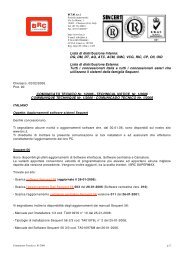
FI010073<br />
M.T.M. s.r.l.<br />
istruzioni di montaggio<br />
assembling instructions<br />
instructions de montage<br />
instrucciones de montaje<br />
Via La Morra, 1<br />
12062 - Cherasco (Cn) - Italy<br />
Tel. ++39 0172 48681<br />
Fax ++39 0172 488237<br />
<strong>Emulatore</strong> <strong>Sonda</strong> <strong>Lambda</strong> <strong>EOBD</strong><br />
<strong>EOBD</strong> <strong>Lambda</strong> Oxygen Sensor Emulator<br />
Emulateur Sonde <strong>Lambda</strong> <strong>EOBD</strong><br />
Emulador <strong>Sonda</strong> <strong>Lambda</strong> <strong>EOBD</strong><br />
memory 5<br />
cod. 06LB00020025<br />
schemi d’installazione ed elenco vetture<br />
installation diagrams and list of vehicles<br />
schémas d’installation et liste des voitures<br />
esquemas de instalación y lista de los vehículos<br />
03 05 01
2 <strong>memory5</strong><br />
Descrizione generale<br />
L’emulatore “Memory 5” evita che si alteri la carburazione a benzina durante il funzionamento a gas. Questo impedisce<br />
che si accenda la spia di Check Engine durante il funzionamento a gas.<br />
L’emulatore “Memory 5” è dotato dell’uscita sonda <strong>Lambda</strong> (filo Giallo) per la centralina controllo gas.<br />
Attenzione<br />
Con l’emulatore “Memory 5” il sistema diagnostico della vettura rimane attivo. Di conseguenza, è necessario che la<br />
carburazione a GAS della vettura sia corretta, in quanto la sonda lambda posteriore potrebbe rilevare delle anomalie<br />
di funzionamento provocando l’accensione della spia check-engine.<br />
Per poter eseguire alla vettura una diagnosi del sistema d’iniezione originale è necessario che la vettura sia commutata<br />
a BENZINA.<br />
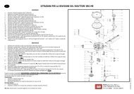
<strong>Sonda</strong> <strong>Lambda</strong> Bosch a 5 fili (fig. 1)<br />
Prima di effettuare l’installazione dell’emulatore verificare i colori della sonda <strong>Lambda</strong> PRIMA del catalizzatore.<br />
<strong>Sonda</strong> <strong>Lambda</strong> NTK a 5 fili (fig. 2)<br />
Prima di effettuare l’installazione dell’emulatore verificare i colori della sonda <strong>Lambda</strong> PRIMA del catalizzatore.<br />
BOSCH<br />
ROSSO<br />
BIANCO<br />
GIALLO<br />
NERO<br />
GRIGIO<br />
Regolazione microinterruttori per auto con iniezione Siemens e sonda lambda Bosch a 5 fili<br />
(fig. 3)<br />
I Microinterruttori sono posizionati nella parte inferiore della scatola, sotto al tappo in gomma. Per un corretto funzionamento<br />
su questi tipi di vetture i microinterruttori devono essere regolati come da schema di fig. 3.<br />
Regolazione microinterruttori per auto con iniezione Marelli e sonda lambda NTK a 5 fili (fig.<br />
4)<br />
I Microinterruttori sono posizionati nella parte inferiore della scatola, sotto al tappo in gomma. Per un corretto funzionamento<br />
su questi tipi di vetture i microinterruttori devono essere regolati come da schema di fig. 4.<br />
BOSCH<br />
FIG. 1<br />
FIG. 3<br />
Descrizione del funzionamento dei LED<br />
Il LED VERDE nella parte superiore della scatola fornisce, durante il funzionamento a gas, le seguenti informazioni:<br />
LED VERDE<br />
Acceso: L’emulatore funziona correttamente.<br />
Lampeggiante o Spento: L’emulatore è alimentato ma vi sono dei problemi<br />
di connessione con la centralina d’iniezione (verificare il collegamento<br />
dei fili sulla presa diagnosi).<br />
Spento: <strong>Emulatore</strong> non alimentato (verificare il collegamento dei fili<br />
LED Verde<br />
Marrone, Verde e Nero).<br />
NTK<br />
BLU<br />
BIANCO<br />
GIALLO<br />
NERO<br />
GRIGIO<br />
ON 1 2 3 ON 1 2 3<br />
NTK<br />
FIG. 2<br />
FIG. 4
<strong>memory5</strong><br />
General description<br />
The “Memory 5” emulator prevents the petrol carburation from altering while running on gas. This saves the checkengine<br />
warning light from turning on while running on gas.<br />
The “Memory 5” emulator is provided with the <strong>Lambda</strong> oxygen sensor outlet (Yellow wire) for the gas ECU.<br />
Warning<br />
With the “Memory 5” emulator the diagnostic system of the vehicle remains operating. It is consequently necessary<br />
for the GAS carburation of the vehicle to be correct, since the rear <strong>Lambda</strong> oxygen sensor could detect malfunctions<br />
by making the check-engine warning light turn on.<br />
In order to carry out a diagnosis of the original injection system, the vehicle ought to change over to PETROL.<br />
5-wire Bosch <strong>Lambda</strong> oxygen sensor (fig. 1)<br />
Before installing the emulator, check the colours of the <strong>Lambda</strong> oxygen sensor BEFORE the catalyser.<br />
5-wire NTK <strong>Lambda</strong> oxygen sensor (fig. 2)<br />
Before installing the emulator, check the colours of the <strong>Lambda</strong> oxygen sensor BEFORE the catalyser.<br />
BOSCH<br />
Adjustment of microswitches for vehicles with Siemens injection and 5-wire Bosch <strong>Lambda</strong><br />
oxygen sensor (fig. 3)<br />
The Microswitches are positioned in the box lower part, under the rubber cap. For a correct working on these types<br />
of vehicles the microswitches ought to be adjusted as per the diagram of the fig. 3.<br />
Adjustment of microswitches for vehicles with Marelli injection and 5-wire NTK <strong>Lambda</strong> oxygen<br />
sensor (fig. 4)<br />
The Microswitches are positioned in the box lower part, under the rubber cap. For a correct working on these types<br />
of vehicles the microswitches ought to be adjusted as per the diagram of the fig. 4.<br />
BOSCH<br />
RED<br />
WHITE<br />
YELLOW<br />
BLACK<br />
GREY<br />
Description of the LEDs working<br />
The GREEN LED in the box upper part supplies, while running on gas, the following data:<br />
GREEN LED<br />
On: The emulator works correctly.<br />
Blinking or Off: The emulator is fed but there are some problems in the<br />
connection with the injection ECU (check the wiring on the diagnostic<br />
point).<br />
Off: The emulator is not fed (check the connection of the Brown, Green<br />
and Black wires).<br />
Green LED<br />
FIG. 1<br />
FIG. 3<br />
BLUE<br />
WHITE<br />
YELLOW<br />
BLACK<br />
ON 1 2 3 ON 1 2 3<br />
NTK<br />
NTK<br />
GREY<br />
3<br />
FIG. 2<br />
FIG. 4
4 <strong>memory5</strong><br />
Description générale<br />
L’émulateur “Memory 5” évite l’altération de la carburation à l’essence lorsque l’on roule au gaz. Ceci empêche l’allumage<br />
de la lampe témoin de check-engine lorsque l’on roule au gaz.<br />
L’émulateur “Memory 5” est pourvu de la sortie sonde <strong>Lambda</strong> (fil Jaune) pour la centrale contrôle gaz.<br />
Attention<br />
Avec l’émulateur “Memory 5” le système diagnostique du véhicule reste actif. Par conséquent, il faut que la carburation<br />
au GAZ du véhicule soit correcte, parce que la sonde <strong>Lambda</strong> postérieure pourrait détecter des anomalies<br />
de fonctionnement en provoquant l’allumage de la lampe témoin check-engine.<br />
Pour effectuer sur le véhicule un diagnostic du système d’injection original, il faut que le véhicule soit commuté à<br />
l’ESSENCE.<br />
Sonde <strong>Lambda</strong> Bosch à 5 fils (fig. 1)<br />
Avant d’effectuer l’installation de l’émulateur, vérifier les couleurs de la sonde <strong>Lambda</strong> AVANT le catalyseur.<br />
Sonde <strong>Lambda</strong> NTK à 5 fils (fig. 2)<br />
Avant d’effectuer l’installation de l’émulateur, vérifier les couleurs de la sonde <strong>Lambda</strong> AVANT le catalyseur.<br />
BOSCH<br />
ROUGE<br />
BLANC<br />
JAUNE<br />
NOIR<br />
GRIS<br />
Réglage microinterrupteurs pour véhicules à injection Siemens et sonde lambda Bosch à 5<br />
fils (fig. 3)<br />
Les Microinterrupteurs sont positionnés dans la partie inférieure de la boîte, au-dessous du bouchon en caoutchouc.<br />
Pour un correct fonctionnement sur ces types de véhicules les microinterrupteurs doivent être réglés d’après<br />
le schéma de la fig. 3.<br />
Réglage microinterrupteurs pour véhicules à injection Marelli et sonde lambda NTK à 5 fils<br />
(fig. 4)<br />
Les Microinterrupteurs sont positionnés dans la partie inférieure de la boîte, au-dessous du bouchon en caoutchouc.<br />
Pour un correct fonctionnement sur ces types de véhicules les microinterrupteurs doivent être réglés d’après<br />
le schéma de la fig. 4.<br />
BOSCH<br />
FIG. 1<br />
FIG. 3<br />
Description du fonctionnement des LEDs<br />
Le LED VERT dans la partie supérieure de la boîte fournit, lorsque l’on roule au gaz, les informations suivantes:<br />
LED VERT<br />
Allumé: L’émulateur fonctionne correctement.<br />
Clignotant ou Eteint: L’émulateur est alimenté mais il y a des problèmes<br />
de connexion avec la centrale d’injection (vérifier la connexion des fils sur<br />
la prise diagnostic).<br />
Eteint: Emulateur non alimenté (vérifier la connexion des fils Marron, Vert<br />
LED Vert<br />
et Noir).<br />
BLEU<br />
BLANC<br />
JAUNE<br />
ON 1 2 3 ON 1 2 3<br />
NTK<br />
NTK<br />
NOIR<br />
GRIS<br />
FIG. 2<br />
FIG. 4
<strong>memory5</strong><br />
Descripción general<br />
El emulador “Memory 5” evita que se altere la carburación de gasolina al funcionar a gas. Esto impide que se<br />
encienda la luz de check-engine al funcionar a gas.<br />
El emulador “Memory 5” está provisto de la salida sonda <strong>Lambda</strong> (cable Amarillo) para la centralita control gas.<br />
Cuidado<br />
Con el emulador “Memory 5” el sistema de diagnóstico del vehículo se queda activo. Por consiguiente, es preciso<br />
que la carburación de GAS del vehículo esté correcta, porque la sonda <strong>Lambda</strong> posterior podría detectar anomalías<br />
de funcionamiento provocando el encendido de la luz check-engine.<br />
Para poder ejecutar en el vehículo un diagnóstico del sistema de inyección original es preciso que el vehículo esté<br />
conmutado a GASOLINA.<br />
<strong>Sonda</strong> <strong>Lambda</strong> Bosch de 5 cables (fig. 1)<br />
Antes de efectuar la instalación del emulador, verifiquen los colores de la sonda <strong>Lambda</strong> ANTES del catalizador.<br />
<strong>Sonda</strong> <strong>Lambda</strong> NTK de 5 cables (fig. 2)<br />
Antes de efectuar la instalación del emulador, verifiquen los colores de la sonda <strong>Lambda</strong> ANTES del catalizador.<br />
BOSCH<br />
Ajuste microinterruptores para vehículos de inyección Siemens y sonda lambda Bosch de 5<br />
cables (fig. 3)<br />
Los Microinterruptores están posicionados en la parte inferior de la caja, debajo de la tapa en goma. Para un correcto<br />
funcionamiento en estos tipos de vehículos los microinterruptores deben ajustarse según el esquema de la<br />
fig. 3.<br />
Ajuste microinterruptores para vehículos de inyección Marelli y sonda lambda NTK de 5<br />
cables (fig. 4)<br />
Los Microinterruptores están posicionados en la parte inferior de la caja, debajo de la tapa en goma. Para un correcto<br />
funcionamiento en estos tipos de vehículos los microinterruptores deben ajustarse según el esquema de la<br />
fig. 4.<br />
BOSCH<br />
ROJO<br />
BLANCO<br />
AMARILLO<br />
NEGRO<br />
GRIS<br />
FIG. 1<br />
FIG. 3<br />
Descripción del funcionamiento de los LEDs<br />
El LED VERDE en la parte superior de la caja suministra, al funcionar a gas, las siguientes informaciones:<br />
LED VERDE<br />
Encendido: El emulador funciona correctamente.<br />
Relampagueante o Apagado: El emulador está alimentado pero hay<br />
problemas de conexión con la centralita de inyección (verifiquen la<br />
conexión de los cables en la toma diagnóstico).<br />
Apagado: Emulador no alimentado (verifiquen la conexión de los cables<br />
LED Verde<br />
Marrón, Verde y Negro).<br />
AZUL<br />
BLANCO<br />
AMARILLO<br />
NEGRO<br />
ON 1 2 3 ON 1 2 3<br />
NTK<br />
NTK<br />
GRIS<br />
5<br />
FIG. 2<br />
FIG. 4
6 <strong>memory5</strong><br />
Marca - Car-maker Modello - Model Iniezione - Injection Schema - Diagram<br />
Marque - Marca Modèle - Modelo Injection - Inyección Schéma - Esquema<br />
AUDI A2 1.4i 16V MPI - AVA 5<br />
SKODA Felicia 1.4i MPI Siemens 5WP44 1<br />
Fabia 1.4i MPI Siemens 5WP44 - ATZ 1<br />
Octavia 1.6i MPI Siemens 5WP40 - AVU 1<br />
SUBARU Forester 2.0i 16V MPI 4<br />
VOLKSWAGEN Polo 1.4i Multipoint - AKK 1<br />
Polo 1.4i 16V MPI Marelli IAW 4LV.KA 2<br />
Golf 1.4i 16V MPI 1<br />
Golf 1.6i MPI Siemens 5WP40 4<br />
Golf 1.6i 16V MPI 5<br />
Bora 1.6i 16V MPI - AZD 5<br />
VOLVO V70 20V T. Multipoint Bosch B5204T5 5<br />
Raccomandazioni<br />
Installare l’emulatore in posizione verticale, lontano da possibili infiltrazioni d’acqua e da eccessive fonti di calore (es. collettori di<br />
scarico).<br />
Installare lontano dalla bobina d’accensione e far passare il cablaggio lontano dai cavi alta tensione.<br />
Realizzare delle buone connessioni elettriche evitando l’uso di “rubacorrente”, eseguendo saldature debitamente isolate.<br />
Non aprire per nessun motivo la scatola dell’emulatore, soprattutto con il motore in moto o con il quadro inserito.<br />
La M.T.M. s.r.l. declina ogni responsabilità per danni a cose o persone derivanti dalla manomissione dell’emulatore da parte di personale<br />
non autorizzato.<br />
Attenzione<br />
Per poter effettuare una diagnosi del sistema d’iniezione originale della vettura è necessario commutare in posizione “forzato benzina”.<br />
Recommendations<br />
Install the emulator in the vertical position, far from any possible water seepage and excessive heat sources (ex. exhaust<br />
manifolds).<br />
Install far from the ignition coil and let the harness pass far from high voltage cables.<br />
Realise good electrical connections without using any shunt cable clamps, by making a duly insulated welding.<br />
Do not open the emulator box, above all with the engine running or with the control board switched on.<br />
The M.T.M. s.r.l. Co. declines all responsibility for damages to things or persons due to unauthorised personnel’s alterations of the<br />
emulator.<br />
Warning<br />
In order to carry out a diagnosis of the vehicle’s original injection system it is necessary to change over to the “forced petrol” mode.<br />
Recommandations<br />
Installer l’émulateur en position verticale, loin de possibles infiltrations d’eau et d’excessives sources de chaleur (ex. collecteurs de<br />
décharge).<br />
Installer loin de la bobine d’allumage et faire passer le câblage loin de câbles à haute tension.<br />
Réaliser de bonnes connexions électriques, en évitant l’emploi de bornes de dérivation et en exécutant des soudures dûment<br />
isolées.<br />
Ne pas ouvrir la boîte de l’émulateur, surtout avec le moteur roulant ou le tableau de bord branché.<br />
La M.T.M. s.r.l. décline toute responsabilité pour des dommages à choses ou personnes dus à une altération de l’émulateur par<br />
personnel non autorisé.<br />
Attention<br />
Pour pouvoir effectuer une diagnostique du système d’injection original de la voiture il faut commuter en position “forcé essence”.<br />
Recomendaciones<br />
Instalen el emulador en posición vertical, lejos de posibles infiltraciones de agua y de excesivas fuentes de calor (ej. colectores de<br />
escape).<br />
Instalen lejos de la bobina de encendido y hagan pasar el cableado lejos de cables de alta tensión.<br />
Realicen buenas conexiones eléctricas evitando el empleo de conectadores toma-señal, ejecutando soldaduras adecuadamente<br />
aisladas.<br />
No abran la caja del emulador, sobre todo con el motor en marcha o con el cuadro de control encendido.<br />
La M.T.M. s.r.l. declina toda responsabilidad por daños a cosas o personas debidos a alteraciones del emulador por parte de personal<br />
no autorizado.<br />
Cuidado<br />
Para poder efectuar un diagnóstico del sistema de inyección original del vehículo hay que conmutar en posición “forzado gasolina”.
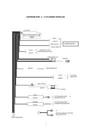
SCHEMA1<br />
Connettore, lato centralina iniezione,<br />
della <strong>Sonda</strong> <strong>Lambda</strong> tipo Bosch posta prima<br />
del catalizzatore<br />
<strong>Lambda</strong> Oxygen Sensor Connector of the<br />
Bosch type, injection ECU side, placed<br />
before the catalyser<br />
SCHEMA2<br />
Sistema di controllo<br />
<strong>Lambda</strong> BRC<br />
BRC <strong>Lambda</strong> Control System<br />
Azzurro-Lt Blue<br />
Non Collegare<br />
Do not connect<br />
Giallo-Yellow<br />
1 3 5<br />
2 4 6<br />
Sistema di controllo<br />
<strong>Lambda</strong> BRC<br />
BRC <strong>Lambda</strong> Control System<br />
Azzurro-Lt Blue<br />
Non Collegare<br />
Do not connect<br />
Giallo-Yellow<br />
1 3 5<br />
2 4 6<br />
Connettore, lato centralina iniezione,<br />
della <strong>Sonda</strong> <strong>Lambda</strong> tipo NTK posta prima<br />
del catalizzatore<br />
<strong>Lambda</strong> Oxygen Sensor Connector of the<br />
NTK type, injection ECU side, placed<br />
before the catalyser<br />
<strong>memory5</strong><br />
Giallo-Yellow<br />
Giallo/Nero-Yellow/Black<br />
Azzurro/Nero-Lt Blue/Black<br />
Giallo-Yellow<br />
Giallo/Nero-Yellow/Black<br />
Azzurro/Nero-Lt Blue/Black<br />
memory 5<br />
memory 5<br />
Marrone-Brown +12V Sotto chiave<br />
+12V After contact<br />
Nero-Black<br />
Massa Motore<br />
Engine Earth<br />
Verde-Green<br />
Elettrovalvola Gas<br />
LPG Solenoid Valve<br />
Bianco-White<br />
Connettore Diagnosi <strong>EOBD</strong><br />
(situato nell’abitacolo)<br />
<strong>EOBD</strong> Diagnostic Connector<br />
(placed in the dashboard)<br />
Bianco/Nero-White/Black<br />
Marrone-Brown<br />
Nero-Black<br />
Verde-Green<br />
Bianco-White<br />
Al filo Verde<br />
E.V. GPL<br />
To the LPG S.V.<br />
Green Wire<br />
Centralina Iniezione<br />
Originale<br />
Original Injection ECU<br />
✂<br />
1<br />
9<br />
2<br />
10<br />
3<br />
11<br />
4<br />
12<br />
Centralina Iniezione<br />
Originale<br />
Original Injection ECU<br />
30<br />
86 85<br />
87<br />
Bianco/Nero-White/Black<br />
5<br />
13<br />
+12V Sotto chiave<br />
+12V After contact<br />
Massa Motore<br />
Engine Earth<br />
6<br />
14<br />
Elettrovalvola Gas<br />
LPG Solenoid Valve<br />
7<br />
15<br />
7<br />
15<br />
8<br />
16<br />
Connettore Diagnosi <strong>EOBD</strong><br />
(situato nell’abitacolo)<br />
<strong>EOBD</strong> Diagnostic Connector<br />
(placed in the dashboard)<br />
1<br />
9<br />
2<br />
10<br />
3<br />
11<br />
4<br />
12<br />
5<br />
13<br />
6<br />
14<br />
7<br />
15<br />
7<br />
15<br />
8<br />
16<br />
7
8 <strong>memory5</strong><br />
SCHEMA3<br />
Connettore, lato centralina iniezione,<br />
della <strong>Sonda</strong> <strong>Lambda</strong> tipo NTK posta prima<br />
del catalizzatore<br />
<strong>Lambda</strong> Oxygen Sensor Connector of the<br />
NTK type, injection ECU side, placed<br />
before the catalyser<br />
SCHEMA4<br />
Sistema di controllo<br />
<strong>Lambda</strong> BRC<br />
BRC <strong>Lambda</strong> Control System<br />
Azzurro-Lt Blue<br />
Non Collegare<br />
Do not connect<br />
Giallo-Yellow<br />
1 3 5<br />
2 4 6<br />
Sistema di controllo<br />
<strong>Lambda</strong> BRC<br />
BRC <strong>Lambda</strong> Control System<br />
Azzurro-Lt Blue<br />
Non Collegare<br />
Do not connect<br />
Giallo-Yellow<br />
1 3 5<br />
2 4 6<br />
Connettore, lato centralina iniezione,<br />
della <strong>Sonda</strong> <strong>Lambda</strong> tipo Bosch posta prima<br />
del catalizzatore<br />
<strong>Lambda</strong> Oxygen Sensor Connector of the<br />
Bosch type, injection ECU side, placed<br />
before the catalyser<br />
Giallo-Yellow<br />
Giallo/Nero-Yellow/Black<br />
Azzurro/Nero-Lt Blue/Black<br />
Giallo-Yellow<br />
Giallo/Nero-Yellow/Black<br />
Azzurro/Nero-Lt Blue/Black<br />
memory 5<br />
memory 5<br />
Marrone-Brown +12V Sotto chiave<br />
+12V After contact<br />
Nero-Black<br />
Massa Motore<br />
Engine Earth<br />
Verde-Green<br />
Elettrovalvola Gas<br />
LPG Solenoid Valve<br />
Bianco-White<br />
Connettore Diagnosi <strong>EOBD</strong><br />
(situato nell’abitacolo)<br />
<strong>EOBD</strong> Diagnostic Connector<br />
(placed in the dashboard)<br />
Bianco/Nero-White/Black<br />
Centralina Iniezione<br />
Originale<br />
Original Injection ECU<br />
Marrone-Brown +12V Sotto chiave<br />
+12V After contact<br />
Nero-Black<br />
Massa Motore<br />
Engine Earth<br />
Verde-Green<br />
Elettrovalvola Gas<br />
LPG Solenoid Valve<br />
Bianco-White<br />
Connettore Diagnosi <strong>EOBD</strong><br />
(situato nell’abitacolo)<br />
<strong>EOBD</strong> Diagnostic Connector<br />
(placed in the dashboard)<br />
Bianco/Nero-White/Black<br />
1<br />
9<br />
2<br />
10<br />
3<br />
11<br />
4<br />
12<br />
Centralina Iniezione<br />
Originale<br />
Original Injection ECU<br />
1<br />
9<br />
2<br />
10<br />
3<br />
11<br />
4<br />
12<br />
5<br />
13<br />
5<br />
13<br />
Non Collegare<br />
Do not connect<br />
6<br />
14<br />
6<br />
14<br />
7<br />
15<br />
7<br />
15<br />
7<br />
15<br />
7<br />
8<br />
16<br />
8<br />
16
SCHEMA5<br />
SCHEMA6<br />
Sistema di controllo<br />
<strong>Lambda</strong> BRC<br />
BRC <strong>Lambda</strong> Control System<br />
Azzurro-Lt Blue<br />
Non Collegare<br />
Do not connect<br />
Giallo-Yellow<br />
1 3 5<br />
2 4 6<br />
Connettore, lato centralina iniezione,<br />
della <strong>Sonda</strong> <strong>Lambda</strong> tipo NTK posta prima<br />
del catalizzatore<br />
<strong>Lambda</strong> Oxygen Sensor Connector of the<br />
NTK type, injection ECU side, placed<br />
before the catalyser<br />
<strong>memory5</strong><br />
Giallo-Yellow<br />
Giallo/Nero-Yellow/Black<br />
Azzurro/Nero-Lt Blue/Black<br />
memory 5<br />
Marrone-Brown +12V Sotto chiave<br />
+12V After contact<br />
Nero-Black<br />
Massa Motore<br />
Engine Earth<br />
Verde-Green<br />
Elettrovalvola Gas<br />
LPG Solenoid Valve<br />
Bianco-White<br />
Connettore Diagnosi <strong>EOBD</strong><br />
(situato nell’abitacolo)<br />
<strong>EOBD</strong> Diagnostic Connector<br />
(placed in the dashboard)<br />
Bianco/Nero-White/Black<br />
Centralina Iniezione<br />
Originale<br />
Original Injection ECU<br />
1<br />
9<br />
2<br />
10<br />
3<br />
11<br />
4<br />
12<br />
5<br />
13<br />
Non Collegare<br />
Do not connect<br />
6<br />
14<br />
7<br />
15<br />
7<br />
8<br />
16<br />
9
10 <strong>memory5</strong><br />
SCHEMA1<br />
Connecteur, côté centrale injection,<br />
de la Sonde <strong>Lambda</strong> type Bosch située avant<br />
le catalyseur<br />
Conectador, lado centralita inyección,<br />
de la <strong>Sonda</strong> <strong>Lambda</strong> tipo Bosch situada<br />
antes del catalizador<br />
SCHEMA2<br />
Système de contrôle<br />
<strong>Lambda</strong> BRC<br />
Sistema de control<br />
<strong>Lambda</strong> BRC<br />
Bleu ciel-Celeste<br />
Jaune-Amarillo<br />
Ne pas Connecter<br />
No conecten<br />
1 3 5<br />
2 4 6<br />
Système de contrôle<br />
<strong>Lambda</strong> BRC<br />
Sistema de control<br />
<strong>Lambda</strong> BRC<br />
Bleu ciel-Celeste<br />
Ne pas connecter<br />
No conecten<br />
Jaune-Amarillo<br />
1 3 5<br />
2 4 6<br />
Connecteur, côté centrale injection,<br />
de la Sonde <strong>Lambda</strong> type NTK située avant<br />
le catalyseur<br />
Conectador, lado centralita inyección,<br />
de la <strong>Sonda</strong> <strong>Lambda</strong> tipo NTK situada antes<br />
del catalizador<br />
Jaune-Amarillo<br />
Jaune/Noir-Amarillo/Negro<br />
Bleu ciel/Noir-Celeste/Negro<br />
Jaune-Amarillo<br />
Jaune/Noir-Amarillo/Negro<br />
Bleu ciel/Noir-Celeste/Negro<br />
memory 5<br />
memory 5<br />
Marron-Marrón<br />
Noir-Negro<br />
Vert-Verde<br />
Blanc-Blanco<br />
Connecteur Diagnostic <strong>EOBD</strong><br />
(situé dans l’habitacle)<br />
Conectador Diagnóstico<br />
<strong>EOBD</strong> (en el habitáculo)<br />
Blanc/Noir-Blanco/Negro<br />
Marron-Marrón<br />
Noir-Negro<br />
Verde-Vert<br />
Blanc-Blanco<br />
Au fil Vert<br />
E.V. GPL<br />
Al cable Verde<br />
E.V. GPL<br />
Centrale Injection Originale<br />
Centralita Inyección<br />
Original<br />
✂<br />
+12V Après le contact<br />
+12V Después del<br />
contacto<br />
Masse Moteur<br />
Tierra Motor<br />
Electrovanne Gaz<br />
Electroválvula Gas<br />
1<br />
9<br />
2<br />
10<br />
3<br />
11<br />
4<br />
12<br />
Centrale Injection Originale<br />
Centralita Inyección<br />
Original<br />
30<br />
86 85<br />
87<br />
Blanc/Noir-Blanco/Negro<br />
5<br />
13<br />
6<br />
14<br />
+12V After contact<br />
+12V Después del<br />
contacto<br />
Masse Moteur<br />
Tierra Motor<br />
Electrovanne GPL<br />
Electroválvula GPL<br />
7<br />
15<br />
7<br />
15<br />
8<br />
16<br />
Connecteur Diagnostic <strong>EOBD</strong><br />
(situé dans l’habitacle)<br />
Conectador Diagnóstico<br />
<strong>EOBD</strong> (en el habitáculo)<br />
1<br />
9<br />
2<br />
10<br />
3<br />
11<br />
4<br />
12<br />
5<br />
13<br />
6<br />
14<br />
7<br />
15<br />
7<br />
15<br />
8<br />
16
SCHEMA3<br />
SCHEMA4<br />
Système de contrôle<br />
<strong>Lambda</strong> BRC<br />
Sistema de control<br />
<strong>Lambda</strong> BRC<br />
Bleu ciel-Celeste<br />
Ne pas Connecter<br />
No conecten<br />
Jaune-Amarillo<br />
1 3 5<br />
2 4 6<br />
Connecteur, côté centrale injection,<br />
de la Sonde <strong>Lambda</strong> type NTK située avant<br />
le catalyseur<br />
Conectador, lado centralita inyección,<br />
de la <strong>Sonda</strong> <strong>Lambda</strong> tipo NTK situada antes<br />
del catalizador<br />
Système de contrôle<br />
<strong>Lambda</strong> BRC<br />
Sistema de control<br />
<strong>Lambda</strong> BRC<br />
Bleu ciel-Celeste<br />
Jaune-Amarillo<br />
Ne pas Connecter<br />
No conecten<br />
1 3 5<br />
2 4 6<br />
Connecteur, côté centrale injection,<br />
de la Sonde <strong>Lambda</strong> type Bosch située avant<br />
le catalyseur<br />
Conectador, lado centralita inyección,<br />
de la <strong>Sonda</strong> <strong>Lambda</strong> tipo Bosch situada<br />
antes del catalizador<br />
<strong>memory5</strong><br />
Jaune-Amarillo<br />
Jaune/Noir-Amarillo-Negro<br />
Bleu ciel/Noir-Celeste/Negro<br />
Jaune-Amarillo<br />
Jaune/Noir-Amarillo/Negro<br />
Bleu ciel/Noir-Celeste/Negro<br />
memory 5<br />
memory 5<br />
Marron-Marrón<br />
Noir-Negro<br />
Vert-Verde<br />
Blanc/Blanco<br />
Connecteur Diagnostic <strong>EOBD</strong><br />
(situé dans l’habitacle)<br />
Conectador Diagnóstico<br />
<strong>EOBD</strong> (en el habitáculo)<br />
Blanc/Noir-Blanco/Negro<br />
Marron-Marrón<br />
Noir-Negro<br />
Vert-Verde<br />
Blanc-Blanco<br />
Connecteur Diagnostic<br />
<strong>EOBD</strong><br />
(situé dans l’habitacle)<br />
Conectador Diagnóstico<br />
<strong>EOBD</strong> (en el habitáculo)<br />
Blanc/Noir-Blanco/Negro<br />
Centrale Injection Originale<br />
Centralita Inyección<br />
Original<br />
+12V Après le contact<br />
+12V Después del<br />
contacto<br />
Masse Moteur<br />
Tierra Motor<br />
Electrovanne Gaz<br />
Electroválvula Gas<br />
1<br />
9<br />
2<br />
10<br />
3<br />
11<br />
4<br />
12<br />
Centrale Injection Originale<br />
Centralita Inyección<br />
Original<br />
Masse Moteur<br />
Tierra Motor<br />
5<br />
13<br />
Electrovanne Gaz<br />
Electroválvula Gas<br />
6<br />
14<br />
+12V Après le contact<br />
+12V Después del<br />
contacto<br />
1<br />
9<br />
2<br />
10<br />
3<br />
11<br />
4<br />
12<br />
5<br />
13<br />
Ne pas Connecter<br />
No conecten<br />
6<br />
14<br />
7<br />
15<br />
7<br />
15<br />
7<br />
15<br />
7<br />
8<br />
16<br />
8<br />
16<br />
11
12 <strong>memory5</strong><br />
SCHEMA5<br />
SCHEMA6<br />
Système de contrôle<br />
<strong>Lambda</strong> BRC<br />
Sistema de control<br />
<strong>Lambda</strong> BRC<br />
Bleu ciel-Celeste<br />
Jaune-Amarillo<br />
Ne pas Connecter<br />
No conecten<br />
1 3 5<br />
2 4 6<br />
Connecteur, côté centrale injection,<br />
de la Sonde <strong>Lambda</strong> type NTK située avant<br />
le catalyseur<br />
Conectador, lado centralita inyección,<br />
de la <strong>Sonda</strong> <strong>Lambda</strong> tipo NTK situada antes<br />
del catalizador<br />
Jaune-Amarillo<br />
Jaune/Noir-Amarillo/Negro<br />
Bleu ciel/Noir-Celeste/Negro<br />
memory 5<br />
Marron-Marrón<br />
Noir-Negro<br />
Vert-Verde<br />
Blanc-Blanco<br />
Connecteur Diagnostic <strong>EOBD</strong><br />
(situé dans l’habitacle)<br />
Conectador Diagnóstico<br />
<strong>EOBD</strong> (en el habitáculo)<br />
Blanc/Noir-Blanco/Negro<br />
Centrale Injection Originale<br />
Centralita Inyección<br />
Original<br />
+12V Après le contact<br />
+12V Después del<br />
contacto<br />
Masse Moteur<br />
Tierra Motor<br />
Electrovanne Gaz<br />
Electroválvula Gas<br />
1<br />
9<br />
2<br />
10<br />
3<br />
11<br />
4<br />
12<br />
5<br />
13<br />
Ne pas Connecter<br />
No conecten<br />
6<br />
14<br />
7<br />
15<br />
7<br />
8<br />
16