Installer's handbook - 1/3 Types of installation - 2/3 Software guide ...
Installer's handbook - 1/3 Types of installation - 2/3 Software guide ...
Installer's handbook - 1/3 Types of installation - 2/3 Software guide ...

Create successful ePaper yourself
Turn your PDF publications into a flip-book with our unique Google optimized e-Paper software.
TA010976 - N. 8 dtd 24.01.2005<br />
M.T.M. s.r.l.<br />
Via La Morra, 1<br />
12062 - Cherasco (Cn) - Italy<br />
Tel. +39 0172 4860140<br />
Fax +39 0172 488237<br />
Installer’s <strong>handbook</strong> - 1/3<br />
<strong>Types</strong> <strong>of</strong> <strong>installation</strong> - 2/3<br />
S<strong>of</strong>tware <strong>guide</strong> - 3/3
INDEX<br />
USEFUL REFERENCES<br />
1. PRESENTATION<br />
2. WHY CHOOSING SEQUENT<br />
3. UNDERSTANDING SEQUENT AND SEQUENT FASTNESS<br />
SYSTEMS<br />
3.1 STRUCTURE<br />
3.2 WORKING PRINCIPLE<br />
3.3 CHANGE-OVER FUNCTION<br />
3.3.1 PETROL OPERATION<br />
3.3.2 GAS OPERATION<br />
3.3.3 FUEL GAUGE: LPG OPERATION<br />
3.3.4 FUEL GAUGE: CNG OPERATION<br />
4. DETAILED DESCRIPTION OF THE COMPONENTS<br />
4.1 SEQUENT GENIUS REDUCER (LPG VERSION)<br />
4.2 SEQUENT GENIUS MAX REDUCER (LPG VERSION)<br />
4.3 SEQUENT GENIUS.M REDUCER (CNG VERSION)<br />
4.4 ZENITH REDUCER (CNG VERSION)<br />
4.5 GAS TEMPERATURE SENSOR<br />
4.6 WATER TEMPERATURE SENSOR (FOR ZENITH REDUCERS)<br />
4.7 “FJ1” FILTER<br />
4.8 “FJ1 TWIN” FILTER<br />
4.9 “FJ1 HE” FILTER (HIGH EFFICIENCY)<br />
4.10 RAIL<br />
4.11 INJECTORS<br />
4.11.1 BRC INJECTOR<br />
4.11.2 KEIHIN INJECTOR<br />
4.12 GAS TEMPERATURE AND PRESSURE SENSOR<br />
4.13 GAS PRESSURE AND MANIFOLD ABSOLUTE PRESSURE (MAP) SENSORS<br />
4.14 MANIFOLD ABSOLUTE PRESSURE (MAP-RAIL SEQUENT FASTNESS)<br />
4.15 “FLY SF” ECU<br />
4.16 CHANGE-OVER SWITCH WITH LEVEL GAUGE<br />
4.17 LEVEL SENSOR<br />
4.18 EMULATING FUNCTION OF INJECTORS<br />
4.19 HARNESS<br />
4.20 NORMAL WP “ET98” LPG SOLENOID VALVE<br />
4.21 SUPER WP “ET98” LPG SOLENOID VALVE<br />
4.22 “VM A3/E” CNG ELECTRO-ASSISTED VALVE<br />
5. MECHANICAL INSTALLATION<br />
5.1 SEQUENT GENIUS REDUCER<br />
5.2 SEQUENT LPG MAX REDUCER<br />
2
5.3 ZENITH CNG REDUCER<br />
5.4 “FJ1” GASEOUS PHASE FILTER<br />
5.5 “FJ1 TWIN” GASEOUS PHASE FILTER<br />
5.6 “FJ1 HE” GASEOUS PHASE FILTER<br />
5.7 RAIL AND INJECTORS GROUP<br />
5.7.1 INSTALLATION OF BRC INJECTORS ON THE RAIL<br />
5.7.2 INSTALLATION OF KEHIN INJECTORS ON THE RAIL<br />
5.7.3 INSTALLATION OF BRC INJECTORS ON THE RAIL WITH PRESSURE SENSOR AND GAS<br />
TEMPERATURE (IN CASE OF ZENITH REDUCER)<br />
5.7.4 INJECTORS’RAIL INSTALLATION IN THE VEHICLE<br />
5.8 PRESSURE SENSOR (P1-MAP, P1-MAP TURBO)<br />
5.9 MAP SENSOR<br />
5.10 PIPES<br />
5.11 NOZZLES<br />
5.12 ECU (ELECTRONIC CONTROL UNIT)<br />
5.13 CHANGE-OVER SWITCH<br />
5.14 HARNESS<br />
5.15 INSTALLATION TYPES<br />
6. ELECTRICAL CONNECTIONS<br />
6.1 CAUTIONS AND DIFFERENCES COMPARED WITH PREVIOUS SYSTEMS<br />
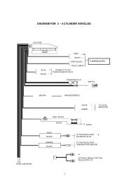
6.2 SEQUENT MAIN HARNESS (REFER TO GENERAL WIRING PLAN PICTURE 2)<br />
6.2.1 CONNECTION OF THE SOLENOID VALVES<br />
6.2.2 56-POLE HARNESS<br />
6.2.3 SEQUENT GENIUS AND GAS TEMPERATURE SENSOR<br />
6.2.4 SUPPLIES AND GROUND FROM BATTERY<br />
6.2.5 FUSES AND RELAY<br />
6.2.6 CHANGE-OVER SWITCH<br />
6.2.7 DIAGNOSTIC POINT<br />
6.2.8 LEVEL SENSOR<br />
6.2.9 SOLENOIDVALVES<br />
6.2.10 GAS TEMPERATURE SENSOR<br />
6.2.11 RAIL P1 PRESSURE SENSOR AND MANIFOLD ABSOLUTE PRESSURE SENSOR (MAP)<br />
6.2.12 GAS INJECTORS<br />
6.2.13 RPM SIGNAL<br />
6.2.14 TPS SIGNAL<br />
6.2.15 OXYGEN SENSOR SIGNAL<br />
6.2.16 POSITIVE KEY CONTACT<br />
6.2.17 10-POLE-CONNECTOR FOR PETROL INJECTORS HARNESS CONNECTION<br />
6.2.17.A Polarity <strong>of</strong> the injectors<br />
6.2.17.B Modular LD<br />
6.2.18 10-POLE CONNECTOR FOR AUXILIARY HARNESS CONNECTION<br />
6.2.18.A Crankshaft Sensor Signal<br />
6.2.18.B Signal for the Ignition Timing Advance Variation<br />
6.2.18.C Engine Water Temperature Signal<br />
3
6.2.18.D Lambda Oxygen Sensor Signal<br />
6.3 SEQUENT MAIN HARNESS (REFER TO GENERAL WIRING PLAN PICTURE 15)<br />
6.3.1 ZENITH SEQUENT AND WATER TEMPERATURE SENSOR<br />
6.3.2 PRESSURE AND GAS TEMPERATURE SENSOR<br />
6.3.3 ABSOLUTE PRESSURE SENSOR MAP<br />
6.3.4 OXYGEN SENSOR SIGNAL (ROW 1) - (ROW 2)<br />
6.3.5 5-POLE-CONNECTOR FOR CRANKSHAFT TO MANAGE ADVANCING AND/OR RPM READING<br />
6.3.5 A Crankshaft Sensor Signal<br />
6.3.5 B Signal for the Ignition Timing Advance Variation<br />
6.4 DESCRIPTION OF THE 5-6-8 CYLINDER HARNESS (FOR ALL<br />
SEQUENT CONFIGURATIONS)<br />
6.4.1 GROUND FROM BATTERY<br />
6.4.2 SUPPLY<br />
6.4.3 RAIL “P1” PRESSURE SENSOR AND MANIFOLD ABSOLUTE PRESSURE SENSOR (MAP)<br />
6.4.4 GAS INJECTORS<br />
6.4.5 10-POLE CONNECTOR FOR PETROL INJECTORS HARNESS CONNECTION<br />
7. GLOSSARY OF TERMS AND<br />
ACRONYMS USED IN THE HANDBOOK<br />
4
USEFUL<br />
REFERENCES<br />
For further information on<br />
“SEQUENT” and “SEQUENT<br />
FASTNESS” systems, it is recommended<br />
to refer to the other <strong>handbook</strong>s<br />
and informative documents<br />
published by BRC.<br />
• Installation types.<br />
They contain the general wiring<br />
diagrams and the <strong>installation</strong><br />
instructions related to the<br />
various types <strong>of</strong> <strong>installation</strong> that<br />
can be found. The cases listed<br />
are mainly distinguished on the<br />
basis <strong>of</strong> the number <strong>of</strong> cylinders,<br />
their location and the vehicle<br />
power. It is especially useful<br />
when the installer works without<br />
specific kits.<br />
• S<strong>of</strong>tware <strong>handbook</strong>.<br />
It is the indispensable <strong>guide</strong> for<br />
those who want to learn managing<br />
the system by means <strong>of</strong> a<br />
personal computer, realising<br />
configurations, programming<br />
ECUs, making diagnosis,<br />
modifying working parameters. It<br />
describes the operation <strong>of</strong> the<br />
“SEQUENT” and “SEQUENT<br />
FASTNESS” s<strong>of</strong>tware, which<br />
runs on Personal Computers, by<br />
driving the user in the various<br />
steps <strong>of</strong> each function.<br />
The modular Common Rail for gas<br />
5
1. INTRODUCTION<br />
Dear installer,<br />
in thanking you for choosing<br />
BRC we wish to give you full information<br />
on “SEQUENT”, the<br />
gaseous LPG or CNG multipoint<br />
sequential injection system. It is a<br />
highly advanced injection system,<br />
result <strong>of</strong> the experience and continuos<br />
BRC’S research in the<br />
gaseous injection field, that can be<br />
installed on vehicles with<br />
sequential multipoint petrol injection.<br />
Thanks to its high level <strong>of</strong> integration,<br />
SEQUENT can assure<br />
higher performances without giving<br />
up simplicity <strong>of</strong> assembly.<br />
Thanks to the high integration <strong>of</strong><br />
the system, SEQUENT can assure<br />
higher performances without compromising<br />
the simplicity <strong>of</strong> the <strong>installation</strong>.<br />
Indeed inside the ECU there<br />
are several functions which allow, in<br />
most cases, avoiding fastidious and<br />
cumbersome devices that, by this<br />
time, each installer is used to<br />
assemble, as Modular, electronic<br />
timing advance processor, crankshaft<br />
sensor adapter, Memory, etc.<br />
From the functional and performance<br />
point <strong>of</strong> view SEQUENT has<br />
the same basic characteristics <strong>of</strong> all<br />
BRC injection systems as a reduce<br />
power loss, no mixer, very small<br />
reducer, no backfire risk but also<br />
adds some new important ones<br />
such as:<br />
• Sequential Injection obtained<br />
by using an electronic injector in<br />
each cylinder;<br />
• High precision for gas dosage<br />
thanks to very precise injectors;<br />
• Auto-diagnosis on ECU<br />
inlet/outlet;<br />
• Protection against short-circuits<br />
<strong>of</strong> the ECU inlet/outlet;<br />
• Communication on K line and<br />
on CAN bus;<br />
Differences compared to other<br />
systems are not only these ones:<br />
some conventions you were used to<br />
have been radically changed. For<br />
this reason please read carefully the<br />
<strong>installation</strong> <strong>guide</strong>s even if you are a<br />
very skilful technician in gas injection<br />
systems.<br />
To convert a vehicle, the installer<br />
will have to use a basic kit and a<br />
standard one. Then he will have to<br />
buy a two-position built-inn changeover<br />
switch, place the components<br />
inside the engine compartment as<br />
indicated in this <strong>guide</strong> and personally<br />
realise the fixing brackets.<br />
The LPG basic kit includes:<br />
• 1 FLY SF ECU without configuration,<br />
• 1 harness (studied for BRC or<br />
Keihin Injectors),<br />
• 1 roll <strong>of</strong> copper pipe ø 6 or ø 8,<br />
• 1 Water pipe 16x23.<br />
• 1 GENIUS or GENIUS MAX<br />
SEQUENT LPG pressure reducer<br />
with gas temperature sensor<br />
at thermistore,<br />
• 1 “FJ1”cartridge filter for gas or<br />
“FJ1 Twin” with double cartridge<br />
• 1 P1 - MAP or P1 - MAP Turbo<br />
pressure sensor,<br />
• 1 LPG “ET98 Normal WP or<br />
ET98 Super WP” solenoid valve,<br />
• 1 bag containing screws, nuts<br />
and various fittings,<br />
The CNG basic kit contains:<br />
• 1 FLY SF ECU without configuration,<br />
• 1 harness (studied for BRC or<br />
Keihin Injectors),<br />
• 1 auxiliary harness<br />
• 1 roll <strong>of</strong> copper or steel pipe,<br />
• 1 Water pipe 8x15<br />
• 1 GENIUS SEQUENT CNG<br />
pressure reducer with gas temperature<br />
sensor at thermistore,<br />
• 1 “FJ1”cartridge filter for gas,<br />
• 1 P1 - MAP CNG pressure<br />
sensor 2,5-4 bar<br />
• 1 “VM A3/E WP classic” CNG<br />
electro-assisted valve,<br />
• 1 CNG pressure gauge with<br />
resistive pressure sensor<br />
• 1 bag containing screws, nuts<br />
6<br />
and various fittings.<br />
The CNG basic kit (Sequent<br />
Fastness version) contains:<br />
• 1 FLY SF ECU without configuration,<br />
• 1 harness (studied for BRC<br />
Injectors),<br />
• 1 auxiliary harness<br />
• 1 roll <strong>of</strong> copper or steel pipe,<br />
• 1 Water pipe 8x15.<br />
• 1 CNG Zenith pressure reducer<br />
with water temperature sensor<br />
at thermistore,<br />
• 1 High efficiency “FJ1 HE” cartridge<br />
filter for gas,<br />
• 1 MAP sensor,<br />
• 1 “VM A3/E WP classic” CNG<br />
electro-assisted valve,<br />
• 1 CNG pressure gauge with<br />
resistive pressure sensor<br />
• 1 bag containing screws, nuts<br />
and various fittings,<br />
The BRC standard kit contains:<br />
• 3 (or 4,5 or 6 depending on the<br />
n. <strong>of</strong> cylinders) BRC gas injectors<br />
with nozzles,<br />
• 1 injectors rail for BRC injectors<br />
with findings,<br />
• Gas pipe 10x17,<br />
• Gas pipes 5x10.5 to be used<br />
on the injectors and pressure<br />
points<br />
• A bag containing: manifold<br />
pressure nozzle, nylon Y piece,<br />
nuts, junctions and “click” clamps<br />
for gas pipe 5x10.5 and<br />
10x17, “click” clamps for the<br />
pressure points, cap M8x1 for<br />
possible RAIL closure.<br />
The Keihin standard kit contains:<br />
• 3 (4, 5 or 6 depending on the<br />
n. <strong>of</strong> cylinders) Keihin gas injectors<br />
with nozzles<br />
• 1 injectors rail for Keihin injectors<br />
with findings,<br />
• Gas pipe 10x17,<br />
• Gas pipes 5x10.5 to be used<br />
on the injectors and pressure<br />
points<br />
• A bag containing: manifold<br />
pressure nozzle, nylon Y piece,<br />
nuts, junctions and “click” clamps<br />
for gas pipe 5x10.5 and<br />
10x17, “click” clamps for the<br />
pressure points, cap M8x1 for
possible RAIL closure.<br />
The BRC standard kit (Sequent<br />
Fastness version) contains:<br />
• 3 (or 4,5 or 6 depending on the<br />
n. <strong>of</strong> cylinders) BRC gas injectors<br />
with nozzles and pressure<br />
and gas temperature sensor<br />
• 1 injectors rail for BRC injectors<br />
with findings,<br />
• Gas pipe 10x17,<br />
• Gas pipes 5x10.5 to be used<br />
on the injectors and pressure<br />
points<br />
• A bag containing: manifold<br />
pressure nozzle, nylon Y piece,<br />
nuts, junctions and “click” clamps<br />
for gas pipe 5x10.5 and<br />
10x17, “click” clamps for the<br />
pressure points, cap M8x1 for<br />
possible RAIL closure.<br />
REDUCERS<br />
Genius LPG LPG<br />
Genius MAX LPG<br />
Zenith CNG<br />
Genius.M CNG<br />
The combinations <strong>of</strong> Gas Injectors/Reducers allow converting<br />
to LPG or CNG the vehicles as in the table hereunder (please<br />
refer to “<strong>Types</strong> <strong>of</strong> Installation” Guide 2/3).<br />
Keihin<br />
LPG<br />
LPG<br />
7<br />
INJECTORS<br />
BRC<br />
LPG<br />
LPG<br />
CNG<br />
Tab.1
2. WHY<br />
CHOOSING<br />
SEQUENT<br />
SEQUENT represents the most<br />
advanced level <strong>of</strong> evolution for what<br />
concerns the equipment <strong>of</strong> gas<br />
injection, and it can be defined to<br />
all intents and purposes as a<br />
“COMMON RAIL” system.<br />
In fact it first introduces, in the<br />
gas propelled field, the winning<br />
evolution used for modern Diesel<br />
engines: a “rail-line” in pressure<br />
(rail) that supplies fuel to all injectors<br />
(true injectors) that are assigned<br />
to inject it in each cylinder <strong>of</strong><br />
the engine.<br />
SEQUENT in addition introduces<br />
the concept <strong>of</strong> modularity <strong>of</strong> the<br />
harness. This operation consists in<br />
the possibility to install the<br />
SEQUENT equipment on the vehicle<br />
through the connection <strong>of</strong> only<br />
three electrical wires and to add<br />
further electrical connections only<br />
and exclusively in case <strong>of</strong> particularly<br />
sophisticated vehicles.<br />
In the SEQUENT system, unlike<br />
an injection at continuos flow<br />
(stream), the ECU calculates the<br />
opening times <strong>of</strong> the injectors,<br />
cylinder per cylinder, and it acts<br />
them separately on each gas injector<br />
with the highest precision and<br />
with the best timing if compared<br />
with the opening instant <strong>of</strong> the<br />
intake valve. The sequential injection<br />
control allows consequently<br />
obtaining the top timeliness and<br />
precision <strong>of</strong> the fuel dosage.<br />
As per all electronic injection<br />
systems, a mixer does not aspirate<br />
the gaseous fuel, but the correct<br />
quantity is determined through the<br />
calculations made by the ECU. It<br />
allows obtaining the well known<br />
advantages <strong>of</strong> the injection<br />
systems, such as:<br />
• No disadvantages in the<br />
performances on petrol, caused<br />
by the absence <strong>of</strong> a mixer,<br />
• Maximum performances on<br />
gas, typical <strong>of</strong> the injection<br />
systems,<br />
• No additional overall dimensions<br />
on the intake pipes,<br />
• Elimination <strong>of</strong> the backfire<br />
risks, due to the injection near<br />
the intake valves and increased<br />
by the fact that injection is in a<br />
timed way with the opening <strong>of</strong><br />
the intake valve.<br />
The result is that the original<br />
sequential injection operation <strong>of</strong> the<br />
vehicle, the engine had been studied,<br />
built and optimised for, is<br />
absolutely unchanged, with the following<br />
practical results:<br />
• Better driving fluidity,<br />
• Consumption optimisation,<br />
• Reduction <strong>of</strong> polluting<br />
exhaust emissions.<br />
Other advantages <strong>of</strong> the system,<br />
which are typical <strong>of</strong> the “in series”<br />
working type and therefore already<br />
known by the BRC installers, are<br />
the following:<br />
• There is no need <strong>of</strong> any specific<br />
emulation for the injectors.<br />
This is usually made by the<br />
same ECU,<br />
• It is normally not necessary to<br />
delete the error codes in the<br />
petrol ECU, because they do not<br />
appear anymore,<br />
• it is not necessary anymore to<br />
install the “Memory” devices on<br />
those vehicles provided by OBD<br />
diagnosis,<br />
• all the petrol ECU functions<br />
remain perfectly efficient even<br />
while running on gas, assuring<br />
the respect <strong>of</strong> the OBD regulations,<br />
• no particular adjustment is<br />
needed, if the configuration is<br />
available.<br />
In addition, thanks to the strong<br />
integration <strong>of</strong> the ECU:<br />
8<br />
• In several cases it is not<br />
necessary to install any outside<br />
devices <strong>of</strong> emulation and interruption<br />
<strong>of</strong> the injectors, as<br />
Modular LD are integrated in the<br />
system harness.<br />
• Possibility <strong>of</strong> reading the<br />
rpm from the crankshaft sensor<br />
without need <strong>of</strong> external<br />
adapters.<br />
• The ECU is provided with an<br />
internal timing advanced processor,<br />
suitable for most vehicles,<br />
• It is possible to connect two<br />
Lambda Sensors without need<br />
<strong>of</strong> adapters,<br />
• The ECU contains the main<br />
adapters for “UEGO” and “in<br />
need <strong>of</strong> power supply” sensors,<br />
• Possibility <strong>of</strong> converting<br />
vehicles up to 8 cylinders in<br />
the two-connector ECU version.
3. UNDERSTANDING<br />
SEQUENT AND<br />
SEQUENT FASTNESS<br />
SYSTEMS<br />
3.1 STRUCTURE<br />
The evolution <strong>of</strong> SEQUENT<br />
system allows introducing new and<br />
more sophisticated components<br />
trying to obtain higher performance.<br />
The system can be used with<br />
different configurations and different<br />
components (LPG Genius,<br />
CNG Genius. M, LPG MAX Genius,<br />
the new Zenith Reducer, BRC or<br />
Keihin rail, etc.) - Table 1 page 7.<br />
This <strong>guide</strong> and the <strong>Types</strong> <strong>of</strong><br />
Installation 2/3 one has the aim to<br />
teach the technician the correct and<br />
different use <strong>of</strong> Sequent and<br />
Sequent Fastness systems.<br />
The SEQUENT systems, starting<br />
from the gas tank to the reducer<br />
included, utilise components,<br />
which are already well known by<br />
the BRC installers. The pressure<br />
reducer, in particular, will be the<br />
GENIUS SEQUENT. It is the same<br />
little-sized reducer <strong>of</strong> simple <strong>installation</strong><br />
already installed on the<br />
Flying Injection, with the difference<br />
that it will be provided with brass<br />
water elbows and a new temperature<br />
sensor, which is not compatible<br />
with the Flying Injection one. The<br />
differences if compared to the previous<br />
conception equipment start<br />
with the rail, connected through the<br />
proper pipe to the GENIUS<br />
SEQUENT outlet, which connects<br />
the gas injectors, supplying them<br />
heated and vaporised gas. A pressure<br />
sensor, that measures the<br />
absolute gas pressure and supplies<br />
injectors, is connected to the rail. If<br />
it is possible to say that the ECU is<br />
the brain <strong>of</strong> the system, the injec-<br />
tors represent its heart. They are<br />
electro-injectors, whose working<br />
principle is quite similar to the one<br />
<strong>of</strong> the petrol injectors, but they differ<br />
from these last ones for:<br />
• Larger passage sections, suitable<br />
for the gaseous fuel,<br />
• Lower electric impedance, to<br />
have quick opening times,<br />
• “Peak & hold” electric piloting,<br />
to have small piloting currents<br />
without disadvantaging performances.<br />
At every injector outlet, the gas<br />
is directly introduced, through proper<br />
pipes, in the air-intake manifold,<br />
downstream the throttle valve.<br />
The changeover switch with<br />
level gauge is <strong>of</strong> the two-position<br />
type, with buzzer. It allows carrying<br />
out the changeover functions from<br />
the petrol-gas and gas-petrol operations,<br />
indicating the gas quantity<br />
present in the tank and moreover<br />
displaying some diagnostic signals<br />
in case <strong>of</strong> malfunction, lack <strong>of</strong> fuel,<br />
not correct programming, etc.<br />
Not least, there is the very<br />
powerful, extremely rugged, completely<br />
waterpro<strong>of</strong> FLY SF ECU,<br />
complying with the EMC regulations,<br />
realised with electronic specific<br />
components for automotive use,<br />
which allow to install it even in the<br />
engine compartment. The ECU collects<br />
and elaborates full information<br />
and checks completely the various<br />
system functions; in particular the<br />
injectors, managing the instant<br />
when the injection happens and its<br />
duration with the precision <strong>of</strong> few<br />
microseconds (microsecond =<br />
1/1000000 <strong>of</strong> second).<br />
The ECU had been studied to<br />
bear short-circuits <strong>of</strong> unlimited<br />
duration on each <strong>of</strong> its inlet/outlet<br />
wires, both towards the ground and<br />
towards the battery positive. It had<br />
been subjected to stringent tests in<br />
order to verify its compliance with<br />
the regulations in the automotive<br />
field.<br />
9<br />
The SEQUENT system communicates<br />
with the outside through a<br />
computer, by means <strong>of</strong> which, with<br />
a valid and powerful interface program,<br />
it is possible to transfer any<br />
information to the ECU, program<br />
itself, calibrate the system, verify<br />
the correct operation, read and<br />
delete the possible error codes<br />
memorised and have information<br />
about the <strong>installation</strong> and about the<br />
memory contents <strong>of</strong> the ECU. The<br />
interface on the computer is therefore<br />
the instrument by means <strong>of</strong><br />
which the installer interacts with the<br />
whole SEQUENT system and by<br />
means <strong>of</strong> which he could “shape”<br />
the gas equipment to fit it to the<br />
vehicle in the different driving conditions.<br />
The tidy collection <strong>of</strong> all files<br />
related to the different <strong>installation</strong>s<br />
made may constitute a very useful<br />
proper historic archive, both to keep<br />
under control the evolutions <strong>of</strong><br />
equipment in the time, and to constitute<br />
a starting point for new<br />
<strong>installation</strong>s.<br />
The <strong>guide</strong> 3/3 has been entirely<br />
dedicated to the interface program<br />
on computer.<br />
NEW<br />
The new sequential gaseous<br />
injection FASTNESS version<br />
comes from Sequent experience<br />
and is for CNG only.<br />
Based on the SEQUENT consolidated<br />
structure, it has new innovations<br />
coming from BRC experience<br />
and recent experimentation with the<br />
aim to make the system stronger,<br />
easy to install and able to solve<br />
even the most difficult problems.<br />
The innovation and changes will<br />
be deeply described in the following<br />
paragraphs <strong>of</strong> the present <strong>guide</strong>:<br />
- System components (reducers,<br />
sensors, etc.)<br />
- S<strong>of</strong>tware and engine control<br />
(new strategies).<br />
Both components and s<strong>of</strong>tware<br />
have been studied to obtain the
easiest operation.<br />
3.2 WORKING PRINCIPLE<br />
SEQUENT is a system that is<br />
placed “in series” with the petrol<br />
system. While running on gas, the<br />
petrol ECU still determinates the<br />
fuel quantity to supply the engine.<br />
SEQUENT is a “passive system” or<br />
“slave”, SEQUENT works as an<br />
“interpreter” between the petrol<br />
system and the gaseous fuel control.<br />
The operation <strong>of</strong> the<br />
SEQUENT system is based on the<br />
fact that the Fly SF ECU is connected<br />
to the petrol ECU terminal/s<br />
piloting injectors (picture 1).<br />
It recognises this way the petrol<br />
injection time (Ti). (While running<br />
on gas, the injectors signal will be<br />
recognised due to the presence <strong>of</strong><br />
the injectors integrated emulation<br />
inside the ECU).<br />
Due to the Ti and the engine<br />
rpm signal, the Fly SF ECU calculates<br />
the petrol flow that the original<br />
ECU tends to supply to the engine,<br />
then converts it into gas flow and<br />
realises it piloting opportunely the<br />
gas injectors. This choice is <strong>of</strong> the<br />
utmost importance, because the<br />
fact <strong>of</strong> enabling the petrol ECU to<br />
be constantly working and piloting<br />
the gas dosage, allows carrying out<br />
clearly and transparently functions<br />
such as stoichiometric control, enrichment<br />
in full load and cut-<strong>of</strong>f following<br />
the criterions expected by<br />
the manufacturer, the restriction <strong>of</strong><br />
the peak rpm, the coherent control<br />
<strong>of</strong> petrol vapours, the correct communication<br />
with the air conditioner<br />
equipment, etc. All this without the<br />
possibility that some counterfeit<br />
error codes could appear. For what<br />
concerns the petrol equipment,<br />
everything remains unchanged,<br />
that is why any error message,<br />
while running on petrol or on gas,<br />
has to be considered real and<br />
believable. Furthermore, if the vehicle<br />
shows some problems in the<br />
Emulator<br />
Injectors<br />
Petrol ECU<br />
Genius or Zenith<br />
petrol operations, they will be maintained<br />
in the gas operation too. It is<br />
absolutely necessary when you<br />
want to comply with the more and<br />
more stringer OBD anti-pollution<br />
regulations, even in the gas operation.<br />
The low impedance gas injectors<br />
are controlled in the peak &<br />
hold mode (see paragraph 4.12),<br />
keeping in mind the physical gas<br />
parameters (temperature and absolute<br />
pressure) read by the Fly SF<br />
ECU in real time (picture 2).<br />
It is important to underline how<br />
the Ti is a precise and precious<br />
parameter, being the result <strong>of</strong><br />
10<br />
Injector/s<br />
Petrol<br />
PETROL<br />
RPM t<br />
Ti<br />
TPS, MAP<br />
Petrol<br />
Flow<br />
Calculation<br />
Gas Flow<br />
Calculation<br />
Problem:<br />
“If we know the gas flow we want to<br />
obtain and knowing the temperature<br />
and gas pressure, compute the Ti<br />
gas <strong>of</strong> the gas injectors”<br />
t<br />
Rail<br />
p1<br />
Gas<br />
flow<br />
Ti<br />
Gas<br />
calculation<br />
Gas flow<br />
p1<br />
Fly SF ECU<br />
Picture 01<br />
Fig. 02<br />
sophisticated calculating elaboration<br />
carried out by the petrol ECU<br />
on the basis <strong>of</strong> a complete and specific<br />
system <strong>of</strong> sensors.<br />
Due to the fact that the temperature<br />
and pressure conditions can<br />
change depending on the conditions<br />
<strong>of</strong> use <strong>of</strong> the vehicle, the<br />
system has temperature sensors<br />
and suitable absolute pressure sensors<br />
placed on the gaseous supply<br />
<strong>of</strong> the injectors and on the airintake<br />
manifolds. The Fly SF ECU<br />
can thus adjust in real time its calculus<br />
and, above all, can correctly<br />
operate even in the presence <strong>of</strong><br />
Ti<br />
Ti<br />
Gas<br />
injector<br />
GAS<br />
(t < 0,005 s)
strong drift <strong>of</strong> aforesaid parameters.<br />
The SEQUENT reducers<br />
(GENIUS, GENIUS.M GENIUS<br />
MAX or ZENITH) tend to keep practically<br />
constant a differential <strong>of</strong><br />
pressure between the gas outlet<br />
pressure and the air-intake<br />
manifold, exactly how it happens in<br />
many petrol systems. This helps<br />
optimising the system working, but<br />
it is not an indispensable fact, as<br />
the control electronics is quicker<br />
than the pressure steady state. For<br />
example, due to a sudden acceleration,<br />
the pressure in the reducer<br />
increases in a fraction <strong>of</strong> second. In<br />
this lapse <strong>of</strong> time, the ECU carries<br />
out several cycles <strong>of</strong> calculus and<br />
obviously compensates every delay<br />
<strong>of</strong> mechanical cause.<br />
Another important aspect <strong>of</strong> the<br />
SEQUENT system is the gas injector.<br />
As it will be subsequently<br />
described, they are low impedance<br />
fuel injectors with large passage<br />
sections, able to obey, in a very<br />
quick way and with great repetitiveness,<br />
to the controls by the Fly SF<br />
ECU, enabling to supply even big<br />
engines.<br />
The Fly SF ECU, in addition to<br />
the general program <strong>of</strong> the system<br />
working, has to contain the specific<br />
data for every vehicle (it is about a<br />
pretty complex whole <strong>of</strong> configurations<br />
and other calibration parameters).<br />
The calibration details can<br />
come from an archive that BRC will<br />
leave at your disposal, or they can<br />
be obtained directly from the installer<br />
through a proper self-calibration<br />
process, driven step to step by the<br />
PC program. The personal computer<br />
works also as a diagnostic<br />
instrument to verify the good<br />
working <strong>of</strong> the system or to spot<br />
any possible anomalies. Inside the<br />
ECU there is also a powerful selforganising<br />
s<strong>of</strong>tware that, perceiving<br />
any possible changes in the vehicle<br />
operation, is able to rectify them<br />
automatically and without any<br />
external help.<br />
3.3 CHANGE-OVER<br />
FUNCTION<br />
The changeover switch (picture<br />
3) has two positions, which allow<br />
the petrol operation and the petrol<br />
starting with automatic changeover<br />
to gas.<br />
The latter one is to be used<br />
for the normal gas operation.<br />
3.3.1 PETROL OPERATION<br />
In this position, the two-colour<br />
LED turns red, the petrol injectors<br />
are working, while the gas ones are<br />
closed, likewise the gas solenoid<br />
valves and the spark advances go<br />
back to default values. The vehicle<br />
regularly runs on petrol, as if the<br />
system were not present (normal<br />
petrol operation).<br />
3.3.2 GAS OPERATION<br />
In this position, the vehicle<br />
starts up on petrol, then, as soon<br />
as the temperature conditions <strong>of</strong><br />
the reducer and the working conditions<br />
<strong>of</strong> the engine (rpm, manifold<br />
pressure, etc.) programmed are<br />
achieved, it changes over automatically<br />
on gas.<br />
While the engine works on<br />
petrol, the two-colour LED turns<br />
red; during the changeover phase<br />
from petrol to gas the LED turns<br />
11<br />
Picture 03<br />
Two-position<br />
changeover switch<br />
with buzzer and<br />
support<br />
orange for an instant (red and<br />
green at the same time); last, when<br />
the changeover phase is over, the<br />
LED turns green and the engine<br />
works on gas (gas normal operation).<br />
In case <strong>of</strong> accidental engine<br />
shutdown, the ECU re-changes<br />
automatically to petrol, independently<br />
<strong>of</strong> the position <strong>of</strong> the changeover<br />
button, and the two-colour LED<br />
turns red (this function is also called<br />
“Safety”). Such a function<br />
moreover prevents the on-<strong>of</strong>f gas<br />
solenoid valves from being energised<br />
for a period longer than 5<br />
seconds after the engine stop.<br />
During gas operation, the ECU<br />
cuts <strong>of</strong>f and emulates injectors, the<br />
gas solenoid valves are open and<br />
the gas injectors are controlled<br />
depending on the fuel demand and<br />
time calculated by the ECU.<br />
3.3.3 FUEL GAUGE: LPG OPE-<br />
RATION<br />
The changeover has moreover<br />
the function <strong>of</strong> fuel gauge through<br />
the four green LEDs. To know how<br />
much LPG is contained in the tank<br />
it is sufficient to see how many<br />
LEDs are turned on. Four LEDs turned<br />
on indicate the full filling <strong>of</strong> the<br />
tank (80% <strong>of</strong> the total tank capacity),<br />
three LEDs on indicate the 3/4<br />
<strong>of</strong> the total filling, two LEDs on<br />
mean half tank, one LED on<br />
mean1/4 <strong>of</strong> tank.<br />
The indication <strong>of</strong> fuel stock is
obtained through the first LED flashing<br />
and is purely indicative. The<br />
correct signal is obtained when the<br />
vehicle is on a level surface and<br />
after a few seconds from the starting,<br />
even if the indication is immediately<br />
present. It is recommended<br />
to use the partial trip odometer<br />
to control the fuel distance. Four<br />
green LEDs flashing mean that<br />
there could be an excessive quantity<br />
<strong>of</strong> LPG in the tank. In this case<br />
it is suggested to run few kilometres<br />
until the flashing ends.<br />
3.3.4 FUEL GAUGE:<br />
CNG OPERATION<br />
To know how much CNG is contained<br />
in the cylinders it is necessary<br />
to connect the level sensor<br />
connector to the BRC manometer<br />
equipped with a pressure sensor.<br />
Four green LEDs lit indicate the<br />
maximum pressure inside the cylinders;<br />
the gradual turning <strong>of</strong>f <strong>of</strong> leds<br />
corresponds to lower pressures<br />
inside the cylinders. As per the LPG<br />
version, also in this case the indication<br />
<strong>of</strong> the fuel stock is obtained<br />
through the first LED flashing and is<br />
purely indicative.<br />
It is recommended to use the<br />
partial trip odometer to control the<br />
fuel distance.<br />
Precautions must be taken<br />
to ensure that the petrol<br />
tank is never allowed to become<br />
empty.<br />
It is necessary to maintain a<br />
petrol quantity corresponding to<br />
1/4 or 1/2 <strong>of</strong> the tank at all times<br />
and to renew it periodically both<br />
for the LPG and for the CNG versions.<br />
12
4. DETAILED<br />
DESCRIPTION OF<br />
THE COMPONENTS<br />
4.1 SEQUENT GENIUS<br />
REDUCER (LPG VERSION)<br />
In the LPG version, the<br />
SEQUENT GENIUS reducer (picture<br />
1) only consists <strong>of</strong> one stage,<br />
with a variable outlet pressure,<br />
which stands approx. 1,2 bar higher<br />
than the air-intake manifold pressure.<br />
Inside the SEQUENT GENIUS<br />
room the LPG evaporation takes<br />
place due to the heat exchange<br />
with the engine coolant liquid, as in<br />
a common reducer. The gas outlet<br />
pressure is controlled by a springdiaphragm-shutter<br />
system, equipped<br />
with proper vibration-damping<br />
systems.<br />
You should observe that (picture<br />
2), a room opens onto the surface<br />
<strong>of</strong> the diaphragm opposite to the<br />
11\one on which the gas pressure<br />
acts. This room is connected to the<br />
air-intake manifold through a pipe.<br />
The gas outlet pressure is therefore<br />
not constant, but follows the intake<br />
manifold pressure course. For<br />
example, in idling conditions, the<br />
manifold pressure if compared with<br />
the ambient could be - 0,6 bar and<br />
the reducer outlet pressure could<br />
be + 0,6 bar.<br />
On the other hand, with a complete<br />
acceleration, the manifold<br />
pressure will be around 0 bar<br />
(atmospheric pressure) and the gas<br />
pressure around +1 bar. Despite<br />
the particular compact dimensions,<br />
the reducer guarantees high gas<br />
flows, to satisfy powers up to 140<br />
kW (190 CV). As it only consists <strong>of</strong><br />
one stage, it does not need any<br />
TEMPERATURE SENSOR<br />
FEEDBACK<br />
WATER<br />
VAPORISED LPG<br />
LIQUID INLET<br />
draining operations. There is a temperature<br />
sensor (picture 3) near the<br />
gas outlet hole which gives full<br />
requisite information to the Fly SF<br />
ECU for a correct flow control. The<br />
petrol-gas changeover is also affected<br />
by temperature, to avoid the<br />
13<br />
Picture 01<br />
Sequent Genius<br />
Reducer<br />
Picture 02<br />
Sequent Genius<br />
Reducer - Sectional<br />
view -<br />
Picture 03<br />
Temperature sensor<br />
passage <strong>of</strong> not completely vaporised<br />
LPG.
4.2 SEQUENT GENIUS MAX<br />
REDUCER (LPG VERSION)<br />
Genius Max reducer has been<br />
studied and studied for being installed<br />
on motor vehicles with elevated<br />
powers motor and for LPG applications.<br />
The outer aspect <strong>of</strong> the reducer<br />
is different from the Genius<br />
Sequent one, while the working<br />
principles are similar.<br />
The reducer is constituted from<br />
a single stage with a variable outlet<br />
pressure that is maintained approximately<br />
1.2 bar more than the pressure<br />
<strong>of</strong> the induction manifold. The<br />
status change <strong>of</strong> the LPG is obtained<br />
through a system shutter-leverspring-diaphragm.<br />
The reducer also contains a circuit<br />
where the engine cooling liquid<br />
allows the thermal exchange<br />
necessary to make the LPG completely<br />
gaseous. A temperature<br />
sensor is on the reducer, too.<br />
This allows the ECU to acquire<br />
the necessary information on Gas<br />
conditions for a correct dosing.<br />
Check the possible cases described<br />
in the <strong>Types</strong> <strong>of</strong> <strong>installation</strong> - 2/3<br />
<strong>guide</strong>.<br />
TEMPERATURE SENSOR<br />
14<br />
WATER VAPORISED LPG LIQUID INLET<br />
Picture 04<br />
Sequent MAX<br />
Genius Reducer<br />
Picture 05<br />
Sequent MAX<br />
Genius Reducer -<br />
Sectional view -<br />
FEEDBACK<br />
Picture 06<br />
Temperature sensor
4.3 SEQUENT GENIUS.M<br />
REDUCER (CNG VERSION)<br />
In the CNG version the reducer,<br />
called SEQUENT GENIUS.M (picture<br />
7), consists <strong>of</strong> two reduction<br />
stages, which have the following<br />
operations:<br />
- to face every CNG pressure<br />
level coming from the tank (load<br />
pressure around 22 MPa corresponding<br />
to 220 bar),<br />
- to spread the CNG at the intermediate<br />
pressure, <strong>of</strong> 500 - 600 kPa<br />
(5 - 6 bar) in a first stage,<br />
- to bring the heat necessary to<br />
avoid an excessive cooling <strong>of</strong> fuel<br />
due to a sudden expansion,<br />
- to spread the CNG further on<br />
at the requested pressure, <strong>of</strong> 200<br />
kPa (2 bar), useful to supply the<br />
injection system. Such a value <strong>of</strong><br />
outlet pressure is conditioned by<br />
the pressure signal <strong>of</strong> the air intake<br />
manifold: in practice, the differential<br />
pressure is kept constant between<br />
the CNG pipe at the outlet <strong>of</strong> the<br />
reducer and the air-intake manifold.<br />
As can be seen from picture 8,<br />
the second stage <strong>of</strong> the SEQUENT<br />
GENIUS.M CNG reducer is very<br />
similar to the first and only stage <strong>of</strong><br />
the SEQUENT GENIUS LPG reducer<br />
version.<br />
Despite the particular compact<br />
dimensions, the reducer guarantees<br />
high gas flows, in order to satisfy<br />
powers up to 140 kW (190CV).<br />
4.4 ZENITH REDUCER<br />
(CNG VERSION)<br />
This is the new reducer for CNG<br />
<strong>installation</strong> and for Sequent<br />
Fastness system only and has<br />
important innovation and improvement.<br />
The reducer consists <strong>of</strong> two<br />
reduction stages with the following<br />
aim:<br />
- to face every CNG pressure<br />
level coming from the tank (load<br />
pressure around 22 MPa corre-<br />
TEMPERATURE SENSOR<br />
FEEDBACK<br />
WATER<br />
GAS INLET<br />
2 ND STAGE<br />
1 ST STAGE<br />
sponding to 220 bar),<br />
- to spread the CNG at the intermediate<br />
pressure, <strong>of</strong> 500 - 600 kPa<br />
(5 - 6 bar) in a first stage,<br />
- to bring the heat necessary to<br />
avoid an excessive cooling <strong>of</strong> fuel<br />
due to a sudden expansion,<br />
15<br />
Picture 07<br />
Sequent M.<br />
Genius Reducer<br />
Picture 08<br />
Sequent M. Genius<br />
Reducer - Sectional<br />
view -<br />
Picture 09<br />
Temperature sensor<br />
- to spread the CNG further on<br />
at the requested pressure, <strong>of</strong> 200<br />
kPa (2 bar), useful to supply the<br />
injection system. Such a value <strong>of</strong><br />
outlet pressure is conditioned by<br />
the pressure signal <strong>of</strong> the air intake<br />
manifold: in practice, the differential
pressure is kept constant between<br />
the CNG pipe at the outlet <strong>of</strong> the<br />
reducer and the air-intake manifold.<br />
In spite <strong>of</strong> the compact dimensions,<br />
the reducer assures high gas<br />
flow able to satisfy engine up to 230<br />
kW.<br />
Zenith pressure reducer is supplied<br />
with a Delta p (∆p) adjustment<br />
equal to about 2000 mbar.<br />
If necessary, this value can be<br />
changed between 1600 and 2500<br />
mbar by the technician by acting on<br />
the suitable screw.<br />
Among the improvements we<br />
point out:<br />
- Swivel-connection with integrated<br />
high efficiency filter (*).<br />
- 1 st reduction stage with lever.<br />
- Safety valve on the 1 st stage.<br />
- 2 nd stage reduction with direct<br />
and desmodromic connection.<br />
- Water circuit built inside the<br />
aluminium body (no washers).<br />
- Temperature water sensor placed<br />
on the reducer (no need to<br />
adjust it) - picture 12.<br />
- Fixing thanks to two M6 holes.<br />
- Pressure compensation<br />
system adjusted according to the<br />
flow.<br />
- Connection on the outlet to the<br />
12x19 pipe rubber holder.<br />
Advantages are the following:<br />
more precise and stable adjustment,<br />
faster response time, possibility<br />
to feed more powerful vehicles<br />
(with equal injectors and basic<br />
Delta P adjustment).<br />
As for its <strong>installation</strong> and the<br />
indications for the power, please<br />
refer to Sequent 2/3 “TYPES OF<br />
INSTALLATIONS” <strong>guide</strong>.<br />
(*) The use <strong>of</strong> the Zenith reducer<br />
excludes the use <strong>of</strong> the filters<br />
described in paragraphs 4.7, 4.8<br />
and 4.9.<br />
WATER<br />
GAS INLET<br />
16<br />
TEMPERATURE SENSOR<br />
Picture 10<br />
CNG Sequent<br />
Zenith reducer<br />
Picture 11 A<br />
CNG Sequent<br />
Zenith reducer -<br />
Sectional view -<br />
1 ST STAGE<br />
2 ND STAGE<br />
FEEDBACK<br />
Picture 11 B<br />
CNG Sequent<br />
Zenith reducer -<br />
Sectional view -
4.5 GAS TEMPERATURE<br />
SENSOR<br />
As mentioned in the previous<br />
paragraphs, a temperature sensor<br />
is installed on LPG and CNG<br />
GENIUS and GENIUS MAX reducers.<br />
The sensor (picture 3,6 and 9)<br />
is resistive, with two wires, based<br />
on NTC thermistore.<br />
All the gas changeover strategies<br />
<strong>of</strong> the system as well as the<br />
calculus <strong>of</strong> the gas injection times<br />
are based on the temperature measured<br />
by the sensor.<br />
The sensor is different from the<br />
one used in the Flying Injection<br />
equipment. Confusing the two sensors<br />
and installing the wrong one,<br />
the ECU will not be able to determine<br />
the correct gas temperature, to<br />
carry out correctly the programmed<br />
changeover strategies and to make<br />
the corrections in the injection<br />
times that depend on gas temperature,<br />
during gas operation.<br />
4.6 WATER TEMPERATURE<br />
SENSOR (FOR ZENITH<br />
REDUCERS)<br />
The temperature sensor shown in<br />
picture 12 is used exclusively on<br />
the new ZENITH reducer.<br />
This is a resistive sensor, with three<br />
wires based on a NTC thermistore.<br />
All strategies for the system changeover<br />
to gas are based on the<br />
water temperature taking.<br />
This sensor differs from previous<br />
one for the mechanical structure: it<br />
is more compact and integrates the<br />
sensor and connector in its inside.<br />
4.7 “FJ1” FILTER<br />
Exclusively used with LPG<br />
Sequent with BRC Injectors and<br />
Genius Reducer, the FJ1 filter carries<br />
out the important function to<br />
trap the LPG or CNG impurities<br />
protecting the injectors working.<br />
It is a cartridge filter, (picture 13)<br />
that is installed just after the redu-<br />
cer-vaporiser and therefore acts on<br />
the gaseous phase. This fact really<br />
differs it from the filter present in<br />
the ET98 solenoid valve, which<br />
works on the liquid. The filtration <strong>of</strong><br />
the gaseous phase allows trapping<br />
all those impurities (oils, waxes,<br />
etc…) on which it would not possible<br />
to act only filtrating the liquid<br />
phase.<br />
Its constructive solution allows<br />
screwing the filtering cartridge on a<br />
17<br />
Picture 12<br />
Water temperature<br />
sensor on the<br />
Zenith reducer<br />
Picture 13<br />
“FJ1” filter with<br />
single cartridge<br />
and threaded<br />
connections<br />
Picture 14<br />
“FJ1 Twin” filter<br />
with double<br />
cartridge and<br />
rubber holder<br />
connections<br />
support and therefore a smooth<br />
intervention <strong>of</strong> substitution.<br />
It is suggested to change it<br />
every 15000 km.<br />
4.8 “FJ1 TWIN” FILTER<br />
Exclusively used with LPG<br />
Sequent System, BRC injectors<br />
and Genius MAX reducer, the FJ1<br />
Twin FILTER has a double cartridge<br />
with characteristics similar to the
previous one but with inlet and<br />
outlet without threaded connection<br />
but with rubber holder ones (picture<br />
14 pag. 17).<br />
4.9 “FJ1 HE” FILTER (HIGH<br />
EFFICIENCY)<br />
Exclusively used with CNG and<br />
LPG Sequent System with Keihin<br />
injectors. FJ1 HE is a very small<br />
cartridge filter. In spite <strong>of</strong> this, the<br />
filter has in its inside a cartridge<br />
that has been studied with innovative<br />
filtering elements allowing it to<br />
have an higher filtering power compared<br />
to the ones used till now (picture<br />
15).<br />
4.10 RAIL<br />
It is the part where the injectors<br />
are assembled on; it enables the gas<br />
distribution to every injector at the<br />
requested pressure.<br />
Available in the following versions:<br />
- for BRC injectors - gas outlet with<br />
threaded union (picture 16) or with<br />
rubber holder one (picture 17),<br />
- for BRC injectors - gas outlet with<br />
rubber holder union and gas temperature<br />
and pressure sensor inside<br />
the rail body. This version is exclusively<br />
used for Sequent Fastness<br />
(picture 18).<br />
- for Keihin injectors - gas outlet with<br />
threaded connection (picture 19) or<br />
with rubber holder one (picture 20).<br />
The first and third rail described<br />
have a threaded connection for the<br />
pipe direct to P1 pressure sensor<br />
while the second (for application<br />
with Zenith reducer) is without and<br />
has a tap to close the hole.<br />
Two threaded holes allow an easy<br />
<strong>installation</strong> <strong>of</strong> the fixing bracket to<br />
the vehicle.<br />
4.11 INJECTORS<br />
4.11.1 BRC INJECTOR<br />
A patent that protects its constructive<br />
details covers BRC<br />
18<br />
Picture 15<br />
“FJ1 HE” filter<br />
with rubber-holder<br />
connections<br />
Picture 16<br />
Version with BRC<br />
injectors and<br />
threaded<br />
connection<br />
Picture 17<br />
Version with BRC<br />
injectors and rubber<br />
holder connection<br />
Picture 18<br />
Version with BRC<br />
injectors, pressure<br />
and gas<br />
temperature sensor<br />
and rubber-holder<br />
connection for<br />
Sequent Fastness<br />
Applications.
injector.<br />
It is a “bottom feed” injector type<br />
(supplied from the bottom).<br />
Referring to fig. 21, the gas contained<br />
inside the rail goes into the<br />
lower side <strong>of</strong> the injector and is<br />
injected in the air intake manifold<br />
when the shutter, moved by the<br />
electromagnet, frees the passage<br />
section.<br />
The tightness is assured by the<br />
rubber final part <strong>of</strong> shutter, which<br />
presses on a volcano.<br />
The pressure differential acting<br />
on the shutter enables it remaining<br />
in the closure position when the coil<br />
is not energised, and prevents gas<br />
from being discharged in the air<br />
intake manifold.<br />
The injector is expressively studied<br />
to have a long life in extreme<br />
conditions <strong>of</strong> use:<br />
• The diaphragms insulate the<br />
very delicate zone <strong>of</strong> the<br />
magnetic circuit, preventing any<br />
gas residual products from<br />
modifying its geometry.<br />
• Working temperature: from –40<br />
°C a +120 °C.<br />
• 15 g accelerations.<br />
• Intense electromagnetic forces<br />
guarantee opening even when<br />
oils or waxes, present in the<br />
dirty gas and not trapped by the<br />
filter, tend to stick the shutter to<br />
its seat.<br />
It is a low impedance injector<br />
(2,04 ohm / 2,35 mH a 20 °C) and<br />
therefore requires a peak & hold<br />
piloting.<br />
The shutter opening time is very<br />
short; it allows having a good control<br />
on the injected gas even in<br />
small dosages, like in idling conditions.<br />
The gas passage sections<br />
allow a correct supply even in the<br />
more powerful vehicles nowadays<br />
available on the market.<br />
To better meet the needs <strong>of</strong> a<br />
fine idling control and a good supply<br />
at high r.p.m. there are two<br />
kinds <strong>of</strong> injectors, with different passage<br />
sections. The injectors (pictu-<br />
19<br />
Picture 19<br />
Version with Keihin<br />
injectors and<br />
threaded<br />
connection<br />
Picture 20<br />
Version with Keihin<br />
injectors and rubber<br />
holder connection<br />
Picture 21<br />
BRC injector -<br />
Sectional view -<br />
Picture 22<br />
Trend <strong>of</strong> the<br />
current inside<br />
BRC injector
e 23) are distinguishable by a<br />
coloured label, that can be Blue for<br />
the BRC injectors Normal type and<br />
Orange for the BRC injectors Max<br />
type.<br />
The table <strong>of</strong> picture 24 shows<br />
the powers that can be supplied by<br />
the BRC injectors depending on the<br />
reducer used*.<br />
4.11.2 KEIHIN INJECTOR<br />
It is a “top feed” injector.<br />
Referring to picture 25, the gas<br />
enters from the top and axially goes<br />
through the shutter to reach the<br />
lower room. When the shutter<br />
opens, attracted towards the top by<br />
the electromagnet, the gas is injected<br />
in the air-intake manifold.<br />
The pressure differential that<br />
acts on the shutter enables it<br />
remaining in the closure position<br />
when the coil is not energised, and<br />
prevents gas from being discharged<br />
in the air intake manifold. The vulcanised<br />
rubber on the bottom <strong>of</strong> the<br />
shutter guarantees both the seal<br />
and the low noise <strong>of</strong> the injector (<<br />
90 dB).<br />
The injector has been expressively<br />
studied to withstand more than<br />
290 million <strong>of</strong> cycles, equal to<br />
100.000 km, in extreme conditions<br />
<strong>of</strong> use:<br />
• The shutter is covered by<br />
teflon so that the injector can<br />
work with no problems <strong>of</strong> wear<br />
with LPG and CNG.<br />
• Working temperature: from<br />
–35°C to +120°C.<br />
• 15 g accelerations.<br />
• Intense electromagnetic forces<br />
guarantee opening even when<br />
oils or waxes, present in the<br />
dirty gas and not trapped by the<br />
filter, tend to stick the shutter to<br />
its seat.<br />
It is a low impedance injector<br />
(1.25 ohm/ 3,5 mH a 20 °C) and<br />
therefore requires a peak & hold<br />
piloting.<br />
LPG feeding capabilities<br />
Genius 800 Genius 1200 Genius 1500 Genius MAX<br />
Injectors Max Type Asp. - 26 kW/cil. 30 kW/cil. 30 kW/cil.<br />
Superch. - 32 kW/cil. 36 kW/cil. 36 kW/cil.<br />
Injectors Normal Type Asp. 17 kW/cil. 21 kW/cil. - -<br />
Superch. 22 kW/cil. 26 kW/cil. - -<br />
CNG feeding capabilities<br />
Zenith ∆p.1600 Zenith ∆p.2000 Zenith ∆p. 2500<br />
Injectors Max Type Asp. 19 kW/cil. 22 kW/cil. 25 kW/cil.<br />
Superch. 22 kW/cil. 25 kW/cil. 29 kW/cil.<br />
Injectors Normal Type Asp. 15 kW/cil. 17 kW/cil. 20 kW/cil.<br />
Superch. 18 kW/cil. 20 kW/cil. 23 kW/cil.<br />
20<br />
Picture 23<br />
BRC Injectors type<br />
“Normal” and “Max”<br />
Picture 24<br />
• The data in the<br />
following chart are<br />
merely indicative.<br />
For the selection <strong>of</strong><br />
the type <strong>of</strong> injectors<br />
please refer to<br />
“<strong>Types</strong> <strong>of</strong><br />
Installation” <strong>guide</strong>.<br />
Picture 25<br />
Keihin injectors -<br />
sectional view<br />
Picture 26<br />
Trend <strong>of</strong> the<br />
current inside<br />
Keihin<br />
injector
Picture 26 shows the typical<br />
trend <strong>of</strong> current in the injector. The<br />
shutter is opened by applying all<br />
the battery voltage during the peak<br />
phase; then the voltage which supplies<br />
the injector becomes the one<br />
called “hold”, as it is sufficient to<br />
keep it open for the necessary time.<br />
The shutter opening time is very<br />
short; it allows having a good control<br />
on the injected gas even in<br />
small dosages, like in the idling<br />
conditions. The gas passage sections<br />
allow a correct supply even in<br />
the more powerful vehicles nowadays<br />
available on the market.<br />
To better meet the needs <strong>of</strong> a<br />
fine idling control and a good supply<br />
at high r.p.m. there are two<br />
kinds <strong>of</strong> injectors, with different passage<br />
sections.<br />
The injectors (picture 27) are<br />
distinguishable by a coloured mark,<br />
placed on the label, that can be<br />
Blue for the Keihin injectors Normal<br />
type, Orange for the Keihin injectors<br />
Max type and Yellow for Keihin<br />
Super Max ones.<br />
Picture 28 depicts the powers<br />
that can be supplied by the Keihin<br />
injectors depending on the used<br />
reducer**.<br />
4.12 GAS TEMPERATURE<br />
AND PRESSURE SENSOR<br />
This new concept sensor with a<br />
small body and integrated inside the<br />
connector also includes the P1 pressure<br />
sensor and the gas temperature<br />
one. As already described in the<br />
previous paragraph, this sensor has<br />
to be installed directly on the injectors<br />
rail for Sequent Fastness applications.<br />
In this position the pressure and<br />
gas temperature measurement is<br />
more precise and allows a quick<br />
intervention for gas carburation corrections.<br />
4.13 GAS PRESSURE<br />
AND MANIFOLD<br />
ABSOLUTE PRESSURE<br />
LPG feeding capabilities<br />
Genius 800 Genius 1200 Genius 1500 Genius Max<br />
Inj. Sup. Max Type Asp. - - 35 kW/cil. 35 kW/cil.<br />
Superch. - - 42 kW/cil. 42 kW/cil.<br />
Inj. Max Type Asp. - 26 kW/cil. 30 kW/cil. 30 kW/cil.<br />
Superch. - 32 kW/cil. 36 kW/cil. 36 kW/cil.<br />
Inj. Normal Type Asp. 17 kW/cil. 21 kW/cil. - -<br />
Superch. 22 kW/cil. 26 kW/cil. - -<br />
CNG feeding capabilities<br />
GeniusM 2000 GeniusM 2500<br />
Inj. Sup. Max Type Asp. - 27 kW/cil.<br />
Superch. - 29 kW/cil.<br />
Inj. Max Type Asp. 20 kW/cil. 23 kW/cil.<br />
Superch. 23 kW/cil. 26 kW/cil.<br />
Inj. Normal Type Asp. 18 kW/cil. 20 kW/cil.<br />
Superch. 20 kW/cil. 23 kW/cil.<br />
(MAP) SENSORS<br />
P1-MAP device (picture 30 and<br />
31) contains two sensors: the P1<br />
sensor that measures the absolute<br />
pressure present in the injectors rail<br />
and the manifold absolute pressure<br />
(MAP) that gives to the Fly SF ECU<br />
the information on the absolute<br />
pressure present inside the airintake<br />
manifold.<br />
The device is pre-amplified so<br />
21<br />
Picture 27<br />
Keihin injectors type<br />
“Normal”, “Max” and<br />
“Super MAX”<br />
Picture 28<br />
** The data in the<br />
following chart are<br />
merely indicative.<br />
For the selection <strong>of</strong><br />
the type <strong>of</strong> injectors<br />
please refer to<br />
“<strong>Types</strong> <strong>of</strong><br />
Installation” <strong>guide</strong>.<br />
Picture 29<br />
Pressure and gas<br />
temperature sensor<br />
inside the Sequent<br />
Fastness rail body<br />
that the signal is not easily disturbed.<br />
The pre-cabled connection<br />
makes the <strong>installation</strong> very simple.<br />
4.14 MANIFOLD ABSOLU-<br />
TE PRESSURE (MAP - RAIL<br />
SEQUENT FASTNESS)<br />
This new sensor (picture 32) is<br />
used for Sequent Fastness only. It<br />
is light, very small and easy to be<br />
installed to the body.
As all the other sensors described<br />
before, its body is compact and<br />
integrated with the connector. It has<br />
in its inside a pressure sensor suitable<br />
for both vacuum and turbo<br />
engines allowing a precise set up<br />
for all vehicles.<br />
4.15 “FLY SF” ECU (SEQUENT<br />
E SEQUENT FASTNESS)<br />
UA detailed description would lie<br />
outside the purposes <strong>of</strong> this <strong>handbook</strong>.<br />
What is important is to know<br />
that it is the operating unit controlling<br />
the whole system. It is completely<br />
made by automotive components,<br />
being therefore suitable to<br />
bear the temperature inside the<br />
engine compartment, even though<br />
precautions must be taken to ensure<br />
that it is not assembled near redhot<br />
devices such as the exhaust<br />
manifold. It is waterpro<strong>of</strong> and is in<br />
compliance with the EMC standards.<br />
It incorporates components<br />
<strong>of</strong> the latest conception (Motorola<br />
32 bit microprocessor), with a data<br />
processing speed higher than most<br />
original petrol ECUs. The memory<br />
that contains calibration program<br />
and data is not volatile, so, once<br />
programmed, the Fly SF ECU (picture<br />
33) can be disconnected from<br />
the battery with no loss <strong>of</strong> data. It<br />
can be programmed more times<br />
without problems, for example it<br />
can be transferred from a vehicle to<br />
another and re-programmed.<br />
Some data acquisition channels<br />
are shared to be connected to different<br />
signals according to the<br />
various vehicles (e.g. TPS, MAP,<br />
etc.).<br />
The task <strong>of</strong> the ECU consists in<br />
collecting and processing full information<br />
and, as a consequence,<br />
controlling the various functions <strong>of</strong><br />
the system; in particular the injectors,<br />
controlling the injection time<br />
and its duration, with a precision <strong>of</strong><br />
few microseconds (microsecond =<br />
1/1000000 <strong>of</strong> second).<br />
The ECU is contained in an alu-<br />
minium rugged waterpro<strong>of</strong> case,<br />
able to bear very high temperatures<br />
and to protect the inside electronic<br />
parts, both from external atmospheric<br />
agents and from mechanical<br />
stresses it is subjected to, and from<br />
electromagnetic radiation irradiated<br />
by the electrical components <strong>of</strong> the<br />
engine or other sources (transmitter,<br />
repeater, mobile phones, etc.).<br />
The ECU has been studied to<br />
withstand prolonged short-circuits,<br />
22<br />
Picture 30<br />
P1-MAP sensor for<br />
aspirated LPG<br />
applications<br />
Picture 31<br />
P1-MAP sensor for<br />
Turbo LPG and<br />
CNG applications<br />
Picture 32<br />
MAP sensor for<br />
Sequent Fastness<br />
applications<br />
both towards the ground and the<br />
battery positive contact, on each <strong>of</strong><br />
its proper inlet/outlet wires (naturally<br />
except for grounds and supplies).<br />
This allows not ruining the ECU<br />
even when in presence <strong>of</strong> the more<br />
common harness errors (inversion<br />
<strong>of</strong> polarity, wrong connection <strong>of</strong> one<br />
or more wires, etc).<br />
The harness connection takes<br />
place through a unique 56-way connector,<br />
which contains all the
necessary signals for the various<br />
functions, as regards the piloting <strong>of</strong><br />
4 injectors at most.<br />
In the two-connector version<br />
(picture 21), a 56-way and a 24way,<br />
two additional types <strong>of</strong> Fly<br />
SF ECU are available: one for<br />
vehicles up to 6 cylinders and<br />
the other for vehicles up to 8<br />
cylinders.<br />
The ECU incorporates the following<br />
functions that were previously<br />
obtained through the <strong>installation</strong><br />
<strong>of</strong> external various components:<br />
• “modular” function to interrupt<br />
and emulate injectors,<br />
• crankshaft sensor adapter<br />
function, more and more useful<br />
on new vehicle models,<br />
• timing advance processor<br />
function, particularly useful for<br />
CNG applications (this function<br />
can not be used for Sequent Fly<br />
SF and Sequent Fastness ECUs<br />
for 8 cylinder vehicles)<br />
• it is possible to connect 2<br />
Lambda oxygen sensors with<br />
no need <strong>of</strong> adapters,<br />
• the ECU contains the main<br />
adapters for “UEGO” and “in<br />
need <strong>of</strong> power supply” oxygen<br />
sensors, to be assembled<br />
externally in other systems.<br />
4.16 CHANGE-OVER<br />
SWITCH<br />
WITH LEVEL GAUGE<br />
It is the BRC two-position changeover<br />
switch, in the standard or<br />
built-in versions, equipped with a<br />
buzzer and a LEDs indicating the<br />
level.<br />
The changeover switch (picture<br />
35 page 24), as mentioned in paragraph<br />
3.3, allows carrying out the<br />
following functions: changeover,<br />
gas level gauging and diagnosis<br />
and can signal irregular situations<br />
(lack <strong>of</strong> gas, breakdowns, automatic<br />
petrol re-changeover, etc.), both<br />
through the LEDs, and the buzzer.<br />
4.17 LEVEL SENSOR<br />
The FLY SF ECU controls the<br />
indication <strong>of</strong> gas level by means <strong>of</strong><br />
a signal on the GREEN LEDs <strong>of</strong> the<br />
changeover switch. To do that, the<br />
ECU is able to elaborate the signal<br />
coming from the BRC resistive level<br />
sensor (PICTURE 36) located on<br />
the multivalve <strong>of</strong> the tank (LPG<br />
equipment), or from the BRC resistive<br />
pressure sensor (PICTURE<br />
37) <strong>of</strong> the CNG equipment. The<br />
thresholds <strong>of</strong> the LEDs are freely<br />
programmable from PC (refer to the<br />
s<strong>of</strong>tware <strong>handbook</strong>), to allow an<br />
accurate precision in the indication.<br />
4.18 EMULATING<br />
FUNCTION OF INJECTORS<br />
The function <strong>of</strong> interrupting the<br />
petrol injectors is completely carried<br />
out by the FLY SF ECU.<br />
The emulating function <strong>of</strong> the<br />
injectors is also carried out by the<br />
23<br />
Picture 33<br />
Fly SF ECU<br />
Picture 34<br />
Fly SF ECU: two<br />
connectors’ version<br />
FLY SF ECU, which incorporates a<br />
proper resistive load.<br />
By “interruption”, we mean the<br />
function that, interrupting the electrical<br />
connection between the petrol<br />
ECU and the injectors, prevents<br />
them from introducing petrol into<br />
the engine cylinders while running<br />
on gas.<br />
During this phase the<br />
SEQUENT system should actually<br />
supply the engine with the gaseous<br />
fuel; a simultaneous introduction <strong>of</strong><br />
petrol, that will damage the engine<br />
and the catalyst, must absolutely<br />
be avoided.<br />
Naturally the petrol ECU diagnosis<br />
is opportunely designed to recognise<br />
the interruptions in the connection<br />
with its actuators, in particular<br />
with the injectors.<br />
It is therefore necessary to<br />
“emulate” the load that was represented<br />
by the petrol injectors, in<br />
other words, to substitute from the<br />
electrical point <strong>of</strong> view the petrol
injectors that have been disconnected,<br />
with “false” injectors, that the<br />
petrol ECU will not distinguish from<br />
the real ones.<br />
As we told before a resistive<br />
type <strong>of</strong> emulation is already present<br />
in the FLY SF ECU anyway some<br />
kind <strong>of</strong> petrol ECUs need not only a<br />
resistive load but a resistive-inductive<br />
one<br />
For this reason inside<br />
SEQUENT harness a suitable<br />
Modular LD has been introduced to<br />
supply the inductive load required<br />
by the petrol ECU during the gas<br />
operation when petrol injectors are<br />
disconnected through the FLY SF<br />
ECU. For further information please<br />
refer to § 6.2.17.B.<br />
4.19 HARNESS<br />
As we indicated before, the harness<br />
is one <strong>of</strong> the main novelties<br />
introduced with the SEQUENT<br />
system. In this paragraph we will<br />
analyse two types with different<br />
characteristics according to the<br />
type <strong>of</strong> Sequent configuration.<br />
The first (picture 38) is the usual<br />
harness used till now for Sequent<br />
application while the second one<br />
(picture 39) is the new harness for<br />
Sequent Fastness only.<br />
The innovative modular harness<br />
allows installing the simpler vehicles<br />
with the only connection <strong>of</strong><br />
three wires (rpm, key contact, TPS:<br />
respectively grey, brown and<br />
white/violet wires), naturally in addition<br />
to the positive and negative<br />
battery.<br />
For more sophisticated vehicles,<br />
that consequently can require more<br />
connections, it is possible to integrate<br />
the harness with further connections<br />
that allow optimising the<br />
vehicle setting up and driving conditions.<br />
Both the main harnesses <strong>of</strong> the<br />
SEQUENT system have a 56-way<br />
connector, used by some <strong>of</strong> the<br />
more important European car<br />
manufacturers.<br />
24<br />
Picture 35<br />
Two positions changeover<br />
switch with<br />
buzzer and without<br />
body<br />
Picture 36<br />
Resistive level<br />
sensor for BRC<br />
Europa Multivalve<br />
Picture 37<br />
Resistive pressure<br />
sensor for BRC<br />
CNG reducers<br />
Picture 38<br />
Fly SF ECU main<br />
harness
If using the two-connector<br />
ECU, a second part <strong>of</strong> harness will<br />
be necessary, to fit a 24-way connector<br />
(picture 40).<br />
Two types 5,6,8-cylinder harness<br />
are available: one for vehicles<br />
up to 6 cylinders and the<br />
other for vehicles up to 8 cylinders.<br />
Shielded conductors have been<br />
used to comply with the EMC standards.<br />
The connectors present on<br />
the harness are waterpro<strong>of</strong>, except<br />
for the one <strong>of</strong> the changeover switch<br />
that is placed in the passenger<br />
compartment and is therefore protected<br />
from water. As regards the<br />
connections <strong>of</strong> wires and harness<br />
connectors you should refer to<br />
chap. 6 <strong>of</strong> the present <strong>handbook</strong>.<br />
NOTE: as the 56 poles connector<br />
used in SEQUENT system is<br />
the same used for Flying Injection<br />
one, considering the similarity <strong>of</strong><br />
the external structure <strong>of</strong> both<br />
systems ECUs, it is possible to<br />
mistake the two ECUs and using<br />
the wrong one for the wrong<br />
system.<br />
Such an error is to be<br />
accurately avoided, because<br />
it can cause the damaging <strong>of</strong><br />
the original components <strong>of</strong> the<br />
vehicle.<br />
Both the main harness (picture<br />
38) and the 5,6,8- cylinder harness<br />
(picture 40) are both available in<br />
the Keihin injectors’ version and in<br />
the BRC injectors one. It is recommended<br />
not to invert such harnesses.<br />
On the other hand, the main<br />
harness for Sequent Fastness<br />
application is available only for BRC<br />
injectors so that you have to pair<br />
the suitable 5-6-8 cylinder harness<br />
with BRC injectors.<br />
4.20 NORMAL WP “ET98”<br />
LPG SOLENOID VALVE<br />
The LPG solenoid valve used in<br />
the SEQUENT system is a waterpro<strong>of</strong><br />
type (with watertight connec-<br />
tors) and is an evolution <strong>of</strong> the wellknown<br />
LPG BRC ET98 solenoid<br />
valve, from which it can be externally<br />
distinguished for the white galvanising<br />
(picture 41). Inside the<br />
LPG solenoid valve, the filtering<br />
system has been improved, in particular<br />
for the iron-magnetic particles.<br />
Due to the precise working <strong>of</strong><br />
the injectors, it is compulsory to use<br />
this kind <strong>of</strong> solenoid valve, in the<br />
whole assembly <strong>of</strong> SEQUENT.<br />
4.21 SUPER WP “ET98”<br />
LPG SOLENOID VALVE<br />
The Super WP “ET98” solenoid<br />
valve is an interception device for<br />
LPG necessary and designed to<br />
grant higher performances compared<br />
to previous ones. An improved<br />
coil allows a more efficient opening<br />
power with the same current. This<br />
permits to have bigger passage<br />
sections and a higher LPG flown.<br />
25<br />
Picture 39<br />
Fly SF ECU main<br />
harness for<br />
Sequent Fastness<br />
applications<br />
Picture 40<br />
5-6-8-cylinder FLY<br />
SF ECU connection<br />
harness<br />
Even in this case the solenoidvalve<br />
has been conceived to allow the<br />
feeding <strong>of</strong> high power engines keeping<br />
a high filtering grade. With<br />
waterpro<strong>of</strong> connectors, the solenoidvalve<br />
body is brass colour<br />
without external covering while the<br />
coil is red (picture 42).<br />
4.22 “VM A3/E” CNG ELEC-<br />
TRO-ASSISTED VALVE<br />
The “VM A3/E” CNG electroassisted<br />
valve used in the<br />
SEQUENT system is <strong>of</strong> the waterpro<strong>of</strong><br />
type (with watertight connectors)<br />
and is an evolution <strong>of</strong> the wellknown<br />
CNG VMA3/E solenoid valve<br />
(picture 43)<br />
The valve, that is usually installed<br />
inside the engine compartment<br />
along the pipes connecting the<br />
CNG cylinder/s to the reducer, if<br />
combined to the IM series CNG filling<br />
adapter, allows refuelling and,<br />
at the same time, the free passage
<strong>of</strong> fuel supply.<br />
The use <strong>of</strong> this kind <strong>of</strong> refuelling<br />
solenoid valve, in the SEQUENT<br />
system context, has a very important<br />
role as the solenoid valve is<br />
controlled and operated by the<br />
electronic control system. It opens<br />
when the starting up begins and<br />
closes in case <strong>of</strong> shutdown, even if<br />
the driver does not turn <strong>of</strong>f the ignition<br />
key (i.e. as it can happen in<br />
case <strong>of</strong> accident).<br />
26<br />
Picture 41<br />
LPG “ET98” WP<br />
solenoidvalve<br />
Picture 42<br />
“ET98 SUPER” WP<br />
LGP solenoidvalve<br />
Picture 43<br />
“VMA3/E” WP<br />
CNG<br />
electro-assisted<br />
valve
5. MECHANICAL<br />
INSTALLATION<br />
The following <strong>installation</strong><br />
rules are to be considered as<br />
general.<br />
Before installing the various<br />
components <strong>of</strong> the Sequent system<br />
it is recommended to check the<br />
petrol operation <strong>of</strong> the vehicle. In<br />
particular, it is necessary to carefully<br />
check the state <strong>of</strong> the electronic<br />
ignition equipment, the air-filter, the<br />
catalyst and the Lambda Oxygen<br />
sensor.<br />
5.1 SEQUENT GENIUS<br />
REDUCER<br />
The following general <strong>installation</strong><br />
rules are to be considered<br />
effective both for the LPG version<br />
and CNG.<br />
The reducer must be firmly<br />
fastened to the bodywork so that it<br />
is not subjected to vibrations during<br />
its operation. With the engine under<br />
stress, the reducer must not hit any<br />
other device. The SEQUENT<br />
GENIUS may be installed with any<br />
orientation (picture 1,2 and 3); it is<br />
not important that the diaphragm is<br />
parallel to the running direction.<br />
The pipe that connects the reducer<br />
to the filter should not be longer<br />
than 200-300 mm. For the connection<br />
see paragraphs 5.10.<br />
If you need to tighten or loosen<br />
the gas inlet fitting or any other fitting,<br />
we recommend to always use<br />
two spanners, in order not to move<br />
the component screwed on the<br />
reducer body.<br />
The temperature sensor wire<br />
should not be too tight or twisted, it<br />
27<br />
Picture 01<br />
Sequent Genius<br />
reducer <strong>installation</strong><br />
with diaphragm<br />
parallel to the<br />
driving direction<br />
Picture 02<br />
Sequent Genius<br />
reducer <strong>installation</strong><br />
with diaphragm<br />
perpendicular to the<br />
driving direction<br />
Picture 03<br />
Sequent Genius<br />
Reducer: further<br />
<strong>installation</strong> position<br />
Picture 04<br />
LPG Sequent<br />
Genius MAX:<br />
possible <strong>installation</strong><br />
position
should nor make sudden folds at<br />
the outlet <strong>of</strong> the sensor.<br />
The copper pipe that goes from<br />
the solenoid valve to the SEQUENT<br />
GENIUS must not go through too<br />
hot areas <strong>of</strong> the engine compartment.<br />
As no adjustment is programmed<br />
on the SEQUENT GENIUS, it<br />
is not essential it is assembled in<br />
an easily accessible area. However<br />
the installer should avoid uneasy<br />
places, in order to make any maintenance<br />
operations without too<br />
many difficulties.<br />
For what concerns the LPG version<br />
it is important to note that<br />
there are rubber-holders connections<br />
for 17x23 pipes on the water<br />
side; they are quite large pipes<br />
because LPG needs to be vaporised<br />
and therefore needs a good<br />
water flow. The water connection<br />
can be made in series or in parallel<br />
as regards the passenger compartment<br />
heating circuit (picture 6 and<br />
7). In phase <strong>of</strong> functional inspection<br />
<strong>of</strong> the equipment installed it is<br />
important to check that the gas<br />
temperature will not reach low<br />
values particularly after a long use<br />
in power.<br />
The CNG Sequent Genius, as it<br />
does not have to perform the vaporisation<br />
function, is equipped with<br />
rubber-holders for 8x15 water<br />
pipes. The connection must be<br />
necessarily parallel: indeed a<br />
connection in series made with<br />
pipes <strong>of</strong> such dimensions would<br />
strongly decrease the passenger<br />
compartment heating.<br />
It is suggested, in this case, to<br />
carefully follow the indications <strong>of</strong><br />
water inlet “IN” and water outlet<br />
“OUT” placed on the reducer.<br />
5.2 SEQUENT LPG<br />
GENIUS MAX REDUCER<br />
General <strong>installation</strong> criteria<br />
described in the previous para-<br />
graph have to be applied for the<br />
SEQUENT LPG GENIUS MAX<br />
reducer.<br />
Unlike Sequent Genius reducer,<br />
the Genius Max has rubber-holders<br />
connections on the outlet so that<br />
pipes have to be tightened using<br />
the suitable supplied click clamps.<br />
5.3 ZENITH CNG REDUCER<br />
General <strong>installation</strong> criteria<br />
28<br />
Picture 05<br />
CNG Sequent<br />
Zenith Reducer:<br />
example <strong>of</strong> <strong>installation</strong><br />
Picture 06<br />
Reducer heating<br />
circuit – parallel<br />
type<br />
Picture 07<br />
Reducer heating<br />
circuit – series type<br />
described in § 5.1 have to be<br />
applied for the Zenith reducer,<br />
too.<br />
As for Genius MAX, the Zenith<br />
reducer has rubber-holders connections<br />
on the outlet so that pipes<br />
have to be tightened using the suitable<br />
supplied click clamps.
5.4 “FJ1” GASEOUS<br />
PHASE FILTER<br />
The filter may be fastened to the<br />
vehicle’s structure or to the engine<br />
with any orientation; but it would be<br />
better to position it with the cartridge<br />
turned downward (picture 8).<br />
The pipe that connects the filter<br />
to the rail should not be longer than<br />
200-300 mm. If you need to tighten<br />
or loosen the fittings, we recommend<br />
to use always two spanners,<br />
in order not to move the component<br />
that is screwed on the filter body.<br />
It is recommended to place the<br />
filter in an accessible area in order<br />
to be able make its programmed<br />
replacement.<br />
N.B. During the filter <strong>installation</strong><br />
it is recommended to follow<br />
the direction <strong>of</strong> the arrow printed<br />
on the upper side <strong>of</strong> the same filter.<br />
It represents the exact course<br />
<strong>of</strong> gas flow, or rather from the<br />
Sequent Genius reducer to the rail.<br />
5.5 “FJ1 TWIN” GASEUOS<br />
PHASE FILTER<br />
The above indications are valid<br />
for the “FJ1 TWIN” filter too (picture<br />
9). The described filter is available<br />
only with rubber-holders connections<br />
and can be used only with the<br />
Genius MAX.<br />
5.6 “FJ1 HE” GASEUOS<br />
PHASE FILTER<br />
The indications in the paragraph<br />
5.4 are valid for the “FJ1 HE” filter,<br />
too. The filter is available only with<br />
rubber-holders connections.<br />
5.7 RAIL AND INJECTORS<br />
GROUP<br />
5.7.1 INSTALLATION OF BRC<br />
INJECTORS ON THE RAIL<br />
The rail always has a connection<br />
to fix the pipe going to the P1<br />
pressure and it is available is two<br />
versions as for the gas inlet that is<br />
with threaded connection or with<br />
rubber-holder one (see picture 11<br />
page 30).<br />
BRC injectors has to be installed<br />
as follow:<br />
• Introduce the O-Ring (1) on<br />
the rail seat (2).<br />
• Introduce the O-Ring (3) on<br />
the injector threaded part (4).<br />
• Introduce the injector (4) in the<br />
29<br />
Picture 08<br />
“FJ1” gaseous<br />
phase filter<br />
Picture 09<br />
“FJ1 TWIN”<br />
gaseous phase filter<br />
Picture 10<br />
“FJ1 HE” gaseous<br />
phase filter<br />
rail seat (2).<br />
• Fix the injector to the rail with<br />
the washer and nut (5). During<br />
the tightening block the injector<br />
in the desired position with one<br />
hand avoiding its rotation.<br />
Do not use pliers or spanners to<br />
block the injector as they can<br />
damage the steel body or the<br />
plastic covering. Use a maximum<br />
torque <strong>of</strong> 8 ± 0,5 Nm.<br />
• Place the fixing bracket (pictu-
e 6) in the car using the screws<br />
and the washers (picture 7).<br />
Please pay attention to the<br />
cleaning during assembly<br />
to avoid dirtiness damage the<br />
injector.<br />
The injector ends with a threaded<br />
part to which you have to connect<br />
the pipe as indicated in § 5.10.<br />
5.7.2 INSTALLATION OF KEHIN<br />
INJECTORS ON THE RAIL<br />
The rail always has a connection<br />
to fix the pipe going to the P1<br />
pressure and it is available is two<br />
versions as for the gas inlet that is<br />
with threaded connection or with<br />
rubber-holder one (see picture 12).<br />
Keihin Injectors must be assembled<br />
as indicated below (fig. 30A):<br />
• Mount the rubber ring (1) and<br />
the O-Ring (2) in its seat on the<br />
injector (3),<br />
• Fit the injector on the rail (4)<br />
without cutting or damaging the<br />
O-Ring (2). It is suggested to<br />
apply a minimum quantity <strong>of</strong><br />
grease on the O-Ring before the<br />
<strong>installation</strong>. Do not apply too<br />
much grease that may overflow<br />
and go inside the injector while<br />
working.<br />
• Once the injectors are mounted<br />
they are fastened to the rail<br />
through a suitable bracket (5).<br />
Two screws and two washers (6)<br />
fix the supporting bracket to the<br />
vehicle (7) and the bracket (5).<br />
After <strong>installation</strong>, the injectors<br />
should not have endplay.<br />
It is recommended to clean<br />
carefully during this <strong>installation</strong>,<br />
to prevent any dirties from<br />
obstructing the filter placed in<br />
the injector inlet, or even worst,<br />
damaging the same injector.<br />
The injector ends with a rubberholder<br />
on which the pipe fixed<br />
through the supplied click clamp is<br />
assembled (see § 5.10).<br />
4<br />
1<br />
2<br />
3<br />
5<br />
5<br />
30<br />
Version with rubber-holder<br />
2<br />
1<br />
4<br />
3<br />
Version with rubber-holder<br />
7<br />
7<br />
6<br />
6<br />
Picture 11<br />
Picture 12
5.7.3 INSTALLATION OF BRC<br />
INJECTORS ON THE RAIL WITH<br />
PRESSURE SENSOR AND GAS<br />
TEMPERATURE SENSOR (IN CASE<br />
OF ZENITH REDUCER)<br />
The difference between this rail<br />
and the previous ones is the introduction<br />
<strong>of</strong> the new pressure and<br />
gas temperature sensor (described<br />
in § 4.11) directly placed on the rail<br />
body (picture 13).<br />
The rail has not the connection<br />
with the P1 pressure sensor (a cap<br />
closes the hole) and always has the<br />
rubber-holder connection on the<br />
gas outlet.<br />
The rail always has a connection<br />
to fix the pipe going to the P1<br />
pressure and it is available is two<br />
versions as for the gas inlet that is<br />
with threaded connection or with<br />
rubber-holder one (see picture 11<br />
page 30).<br />
BRC injectors has to be installed<br />
as follow:<br />
• Introduce the O-Ring (1) on<br />
the rail seat (2).<br />
• Introduce the O-Ring (3) on<br />
the injector threaded part (4).<br />
• Introduce the injector (4) in the<br />
rail seat (2).<br />
• Fix the injector to the rail with<br />
the washer and nut (5). During<br />
the tightening block the injector<br />
in the desired position with one<br />
hand avoiding its rotation.<br />
Do not use pliers or spanners to<br />
block the injector as they can<br />
damage the steel body or the<br />
plastic covering. Use a maximum<br />
torque <strong>of</strong> 8 ± 0,5 Nm.<br />
• Introduce the washer (6) on<br />
the sensor threaded part (7).<br />
• Introduce the sensor (7) in the<br />
rail seat (8).<br />
• Place the fixing bracket (picture<br />
9) in the car using the screws<br />
and the washers (picture 10).<br />
Please pay attention to the<br />
cleaning during assembly to<br />
avoid dirtiness damage the injector.<br />
The injector ends with a threa-<br />
7<br />
6<br />
8<br />
2<br />
4<br />
ded part to which you have to connect<br />
the pipe as indicated in § 5.10<br />
5.7.4 INJECTORS’ RAIL<br />
INSTALLATION IN THE VEHICLE<br />
The rail with the injectors can be<br />
fixed both to the vehicle and to the<br />
engine; the orientation is not important<br />
(picture 14 and picture 15 page<br />
32).<br />
The fixing must be stable; it is<br />
necessary to place the injectors as<br />
close as possible to the engine<br />
head so that the air-intake manifold<br />
connecting pipes are as short as<br />
possible. They should not be longer<br />
than 150 mm.<br />
31<br />
5<br />
3<br />
1<br />
10<br />
9<br />
Fig. 13<br />
Picture 14<br />
Example <strong>of</strong> the rail<br />
<strong>installation</strong> with<br />
BRC injectors<br />
In case <strong>of</strong> BRC the suitable connection<br />
nut has to be assembled on<br />
a pipe end as indicated in the §<br />
5.10.<br />
In case <strong>of</strong> Keihin injectors, pipes<br />
must be fixed to the rubber-holder<br />
through the click clamp and using<br />
the suitable pliers.<br />
Follow the <strong>installation</strong> criteria for<br />
pipes and electric wires indicated in<br />
§ 5.10 and chapter 6.<br />
As the injectors are not noiseless,<br />
it is better not to fix them to<br />
the bulkhead that divides the engine<br />
from the passenger compartment,<br />
because it may become a<br />
resonance box that would amplify<br />
the noise. In case you are compel-
led to choose this position, it is<br />
necessary to equip the fixing<br />
bracket with suitable damping<br />
systems (silent-block).<br />
5.8 PRESSURE SENSOR<br />
(P1-MAP, P1-MAP TURBO)<br />
The P1-MAP sensor has to be<br />
used in LPG applications for aspirated<br />
engine while the P1-MAP<br />
TURBO sensor must be always<br />
used in LPG applications for boosted<br />
engines and in all CNG applications.<br />
The sensor has to be fixed to<br />
the vehicle’s bodywork (picture 16)<br />
avoiding high heat irradiation areas.<br />
It is better than pipes are as short<br />
as possible and anyway no longer<br />
than 400 mm. For the connection<br />
see paragraphs 5.10.<br />
Electrical wires should not be<br />
too stretched, or twisted and they<br />
should not make sudden folds at<br />
the sensor outlet.<br />
5.9 MAP SENSOR<br />
This new sensor is dedicated for<br />
Sequent Fastness application with<br />
Zenith reducer (picture 17).<br />
For assembling instructions follow<br />
all the indications in the previous<br />
paragraph.<br />
5.10 PIPES<br />
The pipes (picture 18,19 and<br />
20) belonging to the Sequent<br />
system are realised by BRC. The<br />
pipes ø 10x17 mm supplied in the<br />
Sequent kit have a fitting on each<br />
ends (picture 18) and pipe ø 5x10,5<br />
mm has the fitting on one end only<br />
(picture 19).<br />
The applications for the P1 sensor<br />
and for BRC injectors you have<br />
to use the ø 5x10,5 mm pipe that<br />
must be cut at the desired length to<br />
allow installing a rubber-holder with<br />
a fitting-nut. In such cases <strong>installation</strong><br />
will be as follows (picture 20):<br />
• Mount the fitting with rubber-<br />
holder (1) on the suitable nut (2).<br />
• Fit the click clamp (3) on the<br />
pipe (4).<br />
• Fit the pipe on the previously<br />
assembled rubber-holder.<br />
• Tighten the pipe on the rubberholder<br />
with the click clamp and the<br />
suitable pliers.<br />
In case <strong>of</strong> Keihin injectors, use<br />
the ø 5x10,5 mm pipe to be fixed<br />
on the free end with the click clamps<br />
without using the rubber-holder<br />
32<br />
Picture 15<br />
Example <strong>of</strong> the rail<br />
<strong>installation</strong> with<br />
Keihin injectors<br />
Picture 16<br />
Example <strong>of</strong> the<br />
P1-Map sensor<br />
<strong>installation</strong><br />
Picture 17<br />
Example <strong>of</strong> the<br />
Sequent Fastness<br />
MAP sensor<br />
<strong>installation</strong><br />
and the connection nut.<br />
Do not leave any rubber residuals<br />
while cutting the pipe or fitting<br />
the rubber-holder; these chips<br />
could obstruct the pipes or other<br />
components <strong>of</strong> the equipment,<br />
prejudicing its working.<br />
Before mounting the pipe it is<br />
recommended to blow it with compressed<br />
air, in order to expel any<br />
impurities or residuals. Verify that<br />
the clamp guarantees tightness.
We recommend not to use pipes<br />
that are different from the ones supplied<br />
and to always mount them<br />
using high-quality wrenches in<br />
order to avoid damaging the hexagons.<br />
Each time it is needed to<br />
remove a fitting, use two wrenches,<br />
in order to hold firmly the component<br />
which is not be unscrewed.<br />
The fittings are tight and they seal<br />
on conical-spherical surfaces. Do<br />
not apply excessive torque wrenches<br />
to avoid damaging the fittings.<br />
Do not use any dope. The usual<br />
criteria related to the correct <strong>installation</strong><br />
<strong>of</strong> pipes should be always<br />
respected, without any relative<br />
motions on running to avoid rubbings<br />
and wears, contacts against<br />
sharp edges or driving belts, etc.<br />
Once mounted, the pipes should<br />
not be too stretched, they should<br />
not make any folds or be positioned<br />
in such a way to have the tendency<br />
to make folds in the future.<br />
4<br />
33<br />
3<br />
2<br />
1<br />
Picture 18<br />
gas pipe ø10x17 to<br />
be used in all kits<br />
where the rail gas<br />
outlet is with<br />
threaded<br />
connection<br />
Picture 19<br />
Gas pipe<br />
ø5x10,5 mm<br />
Picture 20<br />
Pipe-holder<br />
assembly
5.11 NOZZLES<br />
The <strong>installation</strong> <strong>of</strong> the nozzles is<br />
one <strong>of</strong> the most important operations<br />
<strong>of</strong> the whole <strong>installation</strong>.<br />
We recommend to clearly spot<br />
all the points that will be drilled,<br />
before beginning to drill.<br />
Use the specific tools included<br />
in the tool-case for the <strong>installation</strong><br />
<strong>of</strong> the Flying Injection components<br />
code 90AV99004028.<br />
The drill should be quite near<br />
the cylinder head, but preserving<br />
the same distance on all manifold<br />
branches and the same nozzle<br />
orientation. Each nozzle has to be<br />
perpendicular to the intake-pipe<br />
axis, or at least, shape an angle<br />
such to convey the flow towards the<br />
engine and not towards the throttlebody<br />
(picture 21 and 22).<br />
On the plastic manifolds, spot<br />
the areas whose walls are as less<br />
thin as possible.<br />
After having marked properly<br />
the drilling points with a felt-tipped<br />
pen, before starting to drill, verify<br />
with the drilling-machine equipped<br />
with a helicoidal bit, that there are<br />
not overall dimensions such to<br />
avoid the correct drilling <strong>of</strong> all branches<br />
following the direction wanted.<br />
Make a chasing and drill (picture<br />
23).<br />
Use a correctly sharpened 5<br />
mm helicoidal bit, and then thread<br />
with an M6 screw tap (picture 24).<br />
While drilling and threading,<br />
take all necessary measures to prevent<br />
the chips from going into the<br />
manifold.<br />
In particular, we recommend to<br />
frequently remove the chips while<br />
drilling and to grease the bit during<br />
the breaking last phase <strong>of</strong> the wall,<br />
in order to stick the chips to the bit.<br />
The last part <strong>of</strong> wall should broken<br />
slowly so that the chips are very<br />
thin: this way the chips stick better<br />
to the bit and, if any <strong>of</strong> them falls<br />
inside, it would cause no damages.<br />
Even during the M6 threading, it is<br />
necessary to grease, extract and<br />
SI<br />
34<br />
SI NO<br />
SI<br />
Manifold<br />
NO<br />
Engine<br />
Picture 21<br />
Inclination <strong>of</strong> the<br />
drilling on manifolds<br />
Picture 22<br />
Orientation <strong>of</strong> the<br />
holes on the<br />
manifolds<br />
Picture 23<br />
Drilling <strong>of</strong> manifold<br />
Picture 24<br />
Threading <strong>of</strong><br />
manifold
<strong>of</strong>ten clean the screw tap.<br />
By using the two 10-mm wrenches<br />
(fig. 39), screw every single<br />
nozzle to the fitting <strong>of</strong> the 10x17<br />
pipe.<br />
By using two 10 mm wrenches<br />
(picture 25) screw each nozzle to<br />
the used ø 5x10,5 mm pipe connection.<br />
Using some Loctite 83-21<br />
(picture 26) screw the nozzle and<br />
the pipe on the manifold hole. Fit<br />
the nozzles correctly in order to<br />
avoid tightening them excessively<br />
and stripping them.<br />
During the clamping phase it is<br />
recommended to always use a proper<br />
wrench, as the one contained in<br />
the tool-case code 90AV99004028.<br />
Do not change either the inside<br />
diameter <strong>of</strong> the nozzles or their outside<br />
shape.<br />
N.B. In presence <strong>of</strong> small diameter<br />
air-intake manifolds, it can<br />
be necessary to mount some<br />
special nozzles, shorter than the<br />
standard ones.<br />
5.12 ECU (ELECTRONIC<br />
CONTROL UNIT)<br />
It can be fixed both inside the<br />
passenger and in the engine compartment<br />
(picture 28 and 29 page<br />
36). Use the fixing holes on the aluminium<br />
body avoiding to subject the<br />
structure to excessive stresses<br />
(e.g.: do not fix the ECU on a convex<br />
surface, thinking you can tighten<br />
the bolts thoroughly and level<br />
35<br />
Picture 25<br />
Nozzle clamping on<br />
pipe-fitting<br />
Solo per injectors<br />
BRC<br />
Picture 26<br />
Threads-blocker<br />
product<br />
Only for BR<br />
injectors<br />
Picture 27<br />
Nozzle clamping<br />
with pipe on<br />
manifold<br />
Picture 28<br />
ECU <strong>installation</strong><br />
inside passenger<br />
compartment
everything). If available, use always<br />
the suitable fixing bracket.<br />
Avoid too hot areas or subjected<br />
to high thermal radiation. Even<br />
though the ECU is waterpro<strong>of</strong>,<br />
avoid installing it in areas subjected<br />
to continuos dripping water in case<br />
<strong>of</strong> rain, so that the water does not<br />
penetrate and stagnate in the harness<br />
or sheaths.<br />
No adjustment is programmed<br />
on the ECU; it is therefore not<br />
important it is easily accessible. It is<br />
more important, instead, that the<br />
cable going from the ECU with the<br />
computer connection is placed in a<br />
very accessible area and protected<br />
by the cap from possible water infiltration.<br />
5.13 CHANGE-OVER<br />
SWITCH<br />
Choose an easily accessible<br />
and visible place for the driver and<br />
fix the device with the screws supplied.<br />
Substituting the label with the<br />
spare one, the changeover switch<br />
can also be installed in vertical<br />
position. Eliminating the external<br />
body, the changeover switch can be<br />
directly built in the vehicle’s dashboard<br />
using the special tool to drill,<br />
code 90AV99000043.<br />
Specific built-in changeover<br />
switches are also available for<br />
every single vehicle; they are to be<br />
positioned in place <strong>of</strong> the original<br />
switch-cover plates. Please refer to<br />
the price list in force to know the<br />
available models.<br />
Make anyway sure it is always a<br />
specific changeover switch in the<br />
two-position version with buzzer.<br />
5.14 HARNESS<br />
The harness <strong>of</strong> the Sequent<br />
system guarantees the correct transmission<br />
<strong>of</strong> every inlet and outlet<br />
signal <strong>of</strong> the ECU. From a “mechanical”<br />
point <strong>of</strong> view, it is recommended<br />
to place the harness very carefully<br />
and to avoid forcing on the<br />
connections (never pull the wires to<br />
let the connector go through a hole<br />
or to disconnect it!!!). Avoid making<br />
too remarked folds, too strong<br />
clamping, sliding against moving<br />
parts, etc. Avoid certain pieces <strong>of</strong><br />
wires from being too stretched<br />
when the engine is under stress.<br />
Fix opportunely the pieces <strong>of</strong> wire<br />
near the connectors, to prevent<br />
their dangling from wearing them<br />
out in the future. Avoid any contact<br />
with sharp edges (burr the hole<br />
rims and mount some wire-leads).<br />
Avoid placing the wires <strong>of</strong> the<br />
Sequent system too close to the<br />
spark plug cables or to other parts<br />
subjected to high voltage.<br />
Each connector is polarised, for<br />
this reason it is fitted without stress<br />
only in the right direction.<br />
Important: all not pre-cabled<br />
connections should be carried out<br />
through electric brazing (s<strong>of</strong>t soldering)<br />
and opportunely insulated.<br />
The soldering should not be “cold”<br />
and should not risk coming <strong>of</strong>f in<br />
the future. Any unused wire <strong>of</strong> the<br />
harness should be shortened and<br />
separately insulated. Never use<br />
welders that are connected to the<br />
battery <strong>of</strong> the same vehicle, or welders<br />
<strong>of</strong> the quick type.<br />
5.15 INSTALLATION TYPES<br />
For various mechanical and<br />
electrical <strong>installation</strong> types, please<br />
refer to the specific <strong>handbook</strong><br />
2/3.<br />
36<br />
Picture 29<br />
ECU <strong>installation</strong> in<br />
the engine<br />
compartment
6. ELECTRICAL<br />
CONNECTIONS<br />
The following general <strong>installation</strong><br />
rules are to be considered indispensable<br />
for a good understanding<br />
<strong>of</strong> the system.<br />
The FLY SF ECU must be connected<br />
with the electric equipment<br />
<strong>of</strong> the SEQUENT system (supplies,<br />
grounds, signals, sensors, actuators,<br />
etc.) through a 56-pole connector<br />
that contains all the necessary<br />
signals for the various operations,<br />
as regards the piloting up to 4<br />
injectors.<br />
The two-connector (56-way connector<br />
and 24-way connector) version,<br />
the ECU can control vehicles<br />
up to 8 cylinders. Most <strong>of</strong> the harness<br />
wires end on pre-cabled connectors,<br />
therefore it becomes very<br />
easy to connect the components <strong>of</strong><br />
the system to the ECU.<br />
Furthermore, the conductors are<br />
divided into more sheaths, in order<br />
to simplify the <strong>installation</strong> and the<br />
identification <strong>of</strong> the various wires.<br />
All the connections <strong>of</strong> the wires<br />
that do not end on a connector<br />
should be executed by well-done<br />
and duly insulated s<strong>of</strong>t soldering.<br />
Avoid any connections by simply<br />
twisting the wires or using other<br />
scarcely reliable systems. For the<br />
mechanical assembly and the location<br />
<strong>of</strong> the harness, make reference<br />
to the paragraph 5.14 <strong>of</strong> the present<br />
<strong>handbook</strong>.<br />
6.1 CAUTIONS AND DIFFE-<br />
RENCES COMPARED WITH<br />
PREVIOUS SYSTEMS<br />
The SEQUENT system differs<br />
from other BRC systems in some<br />
essential points. It is fundamental to<br />
take note <strong>of</strong> the cautions contained<br />
in this paragraph to avoid <strong>installation</strong><br />
mistakes that can cause the<br />
breaking <strong>of</strong> the gas equipment<br />
components or even damages to<br />
the vehicle’s original equipment. All<br />
the Sequent ECU harness terminals<br />
are waterpro<strong>of</strong> in compliance<br />
with the latest European regulations.<br />
Considering the introduction<br />
<strong>of</strong> the new Sequent<br />
Fastness (Zenith reducer, Rail<br />
with pressure and gas temperature<br />
sensor and Map one) it is<br />
necessary to clearly recognised<br />
the new main harness for<br />
Sequent Fastness (picture 15<br />
page 46) from the old one for<br />
Sequent (picture 2 page 38). For<br />
this reason, the following paragraph<br />
will describe all the electrical<br />
changes <strong>of</strong> the new Fastness<br />
Main Harness.<br />
6.2 SEQUENT MAIN<br />
HARNESS (REFER TO GENERAL<br />
WIRING PLAN IN PICTURE 2)<br />
6.2.1 CONNECTION OF THE<br />
SOLENOID VALVES<br />
An important difference compared<br />
to other BRC systems, that can<br />
cause mistakes if it is not taken into<br />
account, is the connection <strong>of</strong> the<br />
solenoid valves. In the previous<br />
systems, a terminal <strong>of</strong> the solenoid<br />
valve was perpetually connected to<br />
the ground (usually to the vehicle’s<br />
“F” sheath<br />
“E” sheath<br />
(-) (+) (-)<br />
37<br />
Extension cable<br />
cod. 06LB50010062<br />
(+)<br />
body, near the solenoid valve itself),<br />
while the other terminal was<br />
coming from the gas equipment<br />
ECU. In the SEQUENT the philosophy<br />
is different and is similar to<br />
the one used to pilot the injectors<br />
and other actuators on the original<br />
petrol equipment. No solenoid valve<br />
terminal is connected perpetually to<br />
the ground, but a wire comes from<br />
the +12V battery (through fuse and<br />
relay), while the FLY SF ECU controls<br />
the other.<br />
Do not connect directly the<br />
solenoid valve terminals to<br />
the ground: that may cause a<br />
short-circuit and will burn the<br />
fuses on the harness and/or<br />
prejudice the correct operation<br />
<strong>of</strong> the equipment.<br />
Another difference is that there are<br />
piloting wires, separated for the<br />
front and back solenoid valve. This<br />
separation allows the FLY SF ECU<br />
understanding whether and, in<br />
case, which <strong>of</strong> the two solenoid valves<br />
is burnt or in short-circuit. It is<br />
therefore necessary to avoid connecting<br />
the two solenoid valves in<br />
parallel: this may prejudice the ECU<br />
diagnosis function (picture 1).<br />
6.2.2 56-POLES HARNESS<br />
As the 56-pole connector used by<br />
the SEQUENT system is the same<br />
already used for the Flying<br />
Injection, even considering the similarity<br />
<strong>of</strong> the external structure <strong>of</strong><br />
systems, it is possible to confuse the<br />
Picture 01<br />
Connection <strong>of</strong> front<br />
and back<br />
solenoidvalves
"A"<br />
5A<br />
Fuse<br />
Black<br />
Black<br />
Red<br />
Red<br />
15A<br />
Fuse<br />
"B"<br />
10 Poles<br />
Connector<br />
injectors<br />
connection<br />
1° Petrol<br />
Injector<br />
"F"<br />
Relay<br />
"P2"<br />
+ -<br />
Battery<br />
2° Petrol<br />
Injector<br />
1 2 3 4<br />
LPG<br />
S.V.<br />
"P"<br />
"P1" "P4"<br />
(-) (+)<br />
"P3"<br />
3° Petrol<br />
Injector<br />
Changeover Switch<br />
Connector<br />
"C"<br />
10 Poles<br />
Connector<br />
Auxiliary<br />
connection<br />
4° Petrol<br />
Injector<br />
Petrol<br />
Injectors<br />
Sequence<br />
Gas<br />
Inlet<br />
"G"<br />
"Q"<br />
Gas<br />
temperature<br />
Sensor<br />
Diagnostic<br />
Point<br />
3 2 1<br />
"D"<br />
RAIL<br />
38<br />
Brown<br />
+12V Key contact<br />
"I4"<br />
"I3"<br />
"I2"<br />
"I1"<br />
1 2 3 4<br />
1 2 3 4<br />
GAS<br />
Injectors<br />
Sequence<br />
"O"<br />
Yellow<br />
White/Violet<br />
P1<br />
"SEQUENT GENIUS "<br />
Reducer<br />
"E"<br />
Levl<br />
Sensor<br />
(TPS Signal)<br />
Europa<br />
Multivale<br />
FLY SF<br />
Petrol<br />
Injection<br />
ECU<br />
ATTENTION:<br />
- Follow scrupulously the Petrol Injectors and Gas injectors sequence as indicated in the diagram.<br />
- Never connect the back and front Solenoid valve wires to the ground.<br />
- To allow a correct diagnosys <strong>of</strong> the front and back solenoid valve, do not connect them together.<br />
- Never substitute the fuses with others <strong>of</strong> higher load.<br />
Lambda Oxy. Sensor Signal<br />
"N"<br />
"M"<br />
Grey<br />
"L"<br />
"H"<br />
Back<br />
Solenoid Valve<br />
(RPM Signal)<br />
Rail Pressure<br />
Sensor or<br />
Rail Turbo<br />
P1<br />
MAP<br />
Picture 02 - General<br />
wiring diagram
ECU <strong>of</strong> a system with the other one,<br />
fitting it in the wrong equipment.<br />
Such an error must be avoided,<br />
as it can damage the<br />
ECUs and/or the original equipment<br />
<strong>of</strong> the vehicle.<br />
If, after the <strong>installation</strong> <strong>of</strong> the<br />
equipment and the ECU, the vehicle<br />
does not start up, it is a good tip not<br />
to insist, before having checked that<br />
the ECU is <strong>of</strong> the correct type.<br />
6.2.3 SEQUENT GENIUS AND<br />
GAS TEMPERATURE SENSOR<br />
The temperature sensor contained<br />
in the Genius Sequent,<br />
Genius M and Genius Max is different<br />
from the one used for the<br />
Flying Injection.<br />
Confusing the two sensors and<br />
mounting the wrong one, the ECU<br />
will not be able to determine the correct<br />
gas temperature, to act correctly<br />
the programmed changeover strategies<br />
and to make the corrections in<br />
the injection times that depend on<br />
the gas temperature, while running<br />
on gas.<br />
6.2.4 SUPPLIES AND GROUND<br />
FROM BATTERY<br />
Sheath “A” in figure 2 contains<br />
two red and two black wires to be<br />
connected to the car battery: the<br />
red wires to the positive and the<br />
black ones to the negative. It is<br />
important to connect the wires as<br />
they are, allowing that they reach<br />
separately the terminals <strong>of</strong> the battery,<br />
without joining the wires <strong>of</strong><br />
same colour in an only wire or joining<br />
them along the harness.<br />
The grounds must be<br />
always connected to the<br />
battery negative and not to the<br />
vehicle’s structure, engine<br />
ground or other grounds present<br />
on the vehicle.<br />
6.2.5 FUSES AND RELAY<br />
At the outlet <strong>of</strong> the sheath “B”<br />
(see picture 2) there are the two<br />
15A and 5A fuses <strong>of</strong> the SEQUENT<br />
equipment. The harness is supplied<br />
with the two fuses with correct<br />
amperage, fitted in the right place.<br />
It is recommended not to substitute<br />
the fuses with others <strong>of</strong> different<br />
amperage and not to invert their<br />
position. The 5A fuse will be fitted in<br />
the fuse-holder with the smaller<br />
section wires, while the 15A fuse<br />
will be fitted in the fuse-holder with<br />
the larger section wires.<br />
At the outlet <strong>of</strong> the sheath “B”<br />
there is also a relay that the<br />
SEQUENT utilises to interrupt the<br />
battery positive coming from the<br />
actuators.<br />
After finishing the connections, it<br />
is recommended to properly fix and<br />
protect both the fuses and the relay.<br />
6.2.6 CHANGE-OVER SWITCH<br />
The 10-pole multipolar cable “C”<br />
inside the harness, ending on the<br />
10-way connector, is used for the<br />
connection <strong>of</strong> the ECU to the changeover<br />
switch placed in the passenger<br />
compartment (picture 2). In<br />
order to make easier its passage<br />
across the wall openings, it is suggested<br />
to bend the connector by<br />
90° to make it parallel to the wires.<br />
The SEQUENT equipment uses<br />
the BRC two-position changeover<br />
switch with buzzer (see BRC Price<br />
List for sale codes).<br />
6.2.7 DIAGNOSTIC POINT<br />
The PC connection to the FLY<br />
SF ECU is based on a diagnostic<br />
point, directly coming from the harness.<br />
It is the 3-way connector diagnostic<br />
point (female-holder on the<br />
harness), equipped with a protection<br />
cap. The diagnostic point is<br />
usually placed near the 56-pole<br />
connector <strong>of</strong> the ECU. The connecting<br />
cable “D” differs from the one<br />
used for the connection <strong>of</strong> the PC<br />
on the Flying Injection system, for<br />
39<br />
the type <strong>of</strong> connector. For the PC<br />
connection it is necessary to use<br />
the suitable cable code DE512114.<br />
6.2.8 LEVEL SENSOR<br />
The resistive type level sensor<br />
has to be connected directly to the<br />
harness through the 2-pole connector,<br />
pre-cabled (Sheath “E” on<br />
drawing <strong>of</strong> picture 2). There is no<br />
error possibility, because the connector<br />
<strong>of</strong> the level sensor is the only one<br />
<strong>of</strong> this type. The connection between<br />
the ECU and the sensor can be<br />
made through the special extension<br />
cable (06LB50010062) ended on the<br />
special connector <strong>of</strong> the resistive<br />
sensor for the Europa Multivalve. The<br />
sheath “E” also contains the 2-pole<br />
connector for the back solenoid valve<br />
connection (see par. 6.2.8).<br />
6.2.9 SOLENOIDVALVES<br />
The solenoidvalves has to be<br />
connected to the harness through<br />
the pre-cabled connectors connected<br />
to the wires contained in the sheaths<br />
“E” and “F”. The front solenoid valve<br />
will be connected to the connector <strong>of</strong><br />
the sheath “F”, while the rear one<br />
(“Europa” multivalve) will be connected<br />
to the connector <strong>of</strong> sheath “E”<br />
through a suitable extension cable<br />
code 06LB50010062 (picture 1 page<br />
37 and 3 page 40).<br />
The sheath “E” also contains the<br />
connector for the resistive level sensor<br />
described in par. 6.2.8.<br />
6.2.10 GAS TEMPERATURE<br />
SENSOR<br />
The temperature sensor, placed<br />
on the pressure reducer, is <strong>of</strong> the<br />
two-wire resistive type, based on<br />
NTC thermistore. It is a sensor,<br />
which is different from the one used<br />
in the Flying Injection equipment.<br />
By confusing the two sensors and<br />
mounting the wrong one, the ECU<br />
will not be able to determine the<br />
correct gas temperature, to act cor-
ectly the programmed changeover<br />
strategies and to make the corrections<br />
in the injection times that<br />
depend on the gas temperature,<br />
while running on gas. The connection<br />
with the harness comes through<br />
the special 3-way connector<br />
(male-holder on the harness) on<br />
which the 2 wires contained in the<br />
sheath “G” <strong>of</strong> the harness end.<br />
6.2.11 RAIL P1 PRESSURE<br />
SENSOR AND MANIFOLD<br />
ABSOLUTE PRESSURE<br />
SENSOR (MAP)<br />
The P1-MAP pressure sensor is<br />
connected to the harness through a<br />
suitable pre-cabled connector,<br />
which is connected to the wires,<br />
contained in the sheath “H”.<br />
The P1-MAP pressure sensor is<br />
a device containing two sensors in<br />
the same box: one to measure the<br />
gas pressure inside the injector<br />
supplying rail and the other one to<br />
measure the air-intake manifold<br />
pressure.<br />
6.2.12 GAS INJECTORS<br />
The gas injectors are connected<br />
to the harness through the wires<br />
with pre-cabled connectors contained<br />
in the sheaths “I1”, “I2”, “I3”,<br />
“I4” (see picture 2).<br />
The connectors <strong>of</strong> the gas injectors<br />
are numbered from 1 to 4 (or<br />
from 1 to 8 with the two-connector<br />
ECU); the same for the sheaths <strong>of</strong><br />
the wires that will be connected to<br />
the petrol injectors.<br />
It is very important to maintain<br />
the correspondence<br />
between gas and petrol injectors.<br />
In practice, the gas injector connected<br />
to the connector n° l1<br />
should correspond to the cylinder<br />
containing the petrol injector to<br />
which we will connect the injector<br />
connection Sequent plug (or the<br />
Orange and Violet wires <strong>of</strong> the universal<br />
injector connection Sequent<br />
harness) marked with the n° P1,<br />
Guaina “E”<br />
Extention cable<br />
cod. 06LB50010062<br />
and so on. In case there is no correspondence,<br />
you will note a worsening<br />
in the equipment performances,<br />
such as, for example: worse<br />
driving conditions, higher unsteadiness<br />
<strong>of</strong> the lambda control, less<br />
“clean” petrol/gas changeover, etc.<br />
The number that distinguishes<br />
the gas injectors’ connectors<br />
is stamped on the harness<br />
wires coming to the same connector.<br />
6.2.13 RPM SIGNAL<br />
The SEQUENT system is able<br />
to acquire the engine speed signal<br />
(<strong>of</strong>ten indicated as “rpm signal”) by<br />
connecting directly to the rpm indicator.<br />
It is sufficient to connect the<br />
Grey wire contained in the sheath<br />
“L” to the original equipment rpm<br />
indicator signal wire going from the<br />
petrol ECU to the revolution counter<br />
in the dashboard. This wire is not to<br />
be cut but only stripped, welded<br />
with the wire <strong>of</strong> the SEQUENT harness<br />
and insulated (picture 2 page<br />
38).<br />
6.2.14 TPS SIGNAL<br />
In the sheath “M” there is the<br />
White/Violet wire to be connected<br />
to the TPS wire (throttle valve position<br />
sensor) <strong>of</strong> the original equipment;<br />
this wire should not be cut,<br />
but only stripped, soldered with the<br />
wire <strong>of</strong> the SEQUENT harness and<br />
40<br />
(+)<br />
(-)<br />
Fig. 03<br />
insulated. The TPS wire, if not correctly<br />
connected, can enable the<br />
SEQUENT system to work<br />
nevertheless in a sort <strong>of</strong> steady<br />
condition but it can deteriorate the<br />
driving conditions, in particular in<br />
sudden accelerations and tip-outs.<br />
6.2.15 OXYGEN SENSOR SIGNAL<br />
In the sheath “N” there is the<br />
Yellow wire to be connected, if<br />
necessary, to the wire <strong>of</strong> the<br />
Lambda Oxygen sensor, placed<br />
before the catalyst. This wire is not<br />
to be cut but only stripped, welded<br />
with the wire <strong>of</strong> the SEQUENT harness<br />
and insulated.<br />
The connection <strong>of</strong> the Yellow<br />
wire allows a quicker self-learning<br />
by the FLY SF ECU and is therefore<br />
very useful in the event <strong>of</strong> the selflearning<br />
phase requiring a further<br />
configuration refinement (refer to<br />
the s<strong>of</strong>tware hand-book).<br />
6.2.16 POSITIVE KEY CONTACT<br />
The Brown wire <strong>of</strong> the<br />
SEQUENT equipment, contained in<br />
the sheath indicated with the letter<br />
“O” in picture 2, has to be connected<br />
to the key contact positive<br />
signal <strong>of</strong> the original equipment.<br />
This wire has not to be cut but only<br />
stripped, welded with the wire <strong>of</strong><br />
the SEQUENT harness and insulated.<br />
6.2.17 10-POLE-CONNECTOR
FOR PETROL INJECTORS<br />
HARNESS CONNECTION<br />
The interruption <strong>of</strong> the petrol<br />
injector is possible by using the “P”<br />
sheath ending with a 10-pole-connector.<br />
You only have to connect<br />
one <strong>of</strong> the specific harnesses for<br />
the petrol injectors’ stopping according<br />
to the type in the vehicle<br />
(Bosch or Sumitomo).<br />
List <strong>of</strong> the codes for Bosch connector<br />
harnesses:<br />
• code 06LB50010102 Right<br />
(DX) Sequent connection harness<br />
for 4 petrol injectors<br />
• code 06LB50010103 Left (SX)<br />
Sequent connection harness for 4<br />
petrol injectors,<br />
• code 06LB50010105 Right<br />
(DX) Sequent connection harness<br />
for 2 petrol injectors,<br />
• code 06LB50010106 Left (SX)<br />
Sequent connection harness for 4<br />
petrol injectors,<br />
• code 06LB50010101 Universal<br />
Sequent connection harness for 4<br />
petrol injectors,<br />
• code 06LB50010104 Universal<br />
Sequent connection harness for 2<br />
petrol injectors,<br />
to be chosen according to the<br />
petrol injectors’ polarity.<br />
List <strong>of</strong> the codes for Sumitomo<br />
connector harnesses:<br />
• code 06LB50010113 Right<br />
(DX) Sequent connection harness<br />
for 4 petrol injectors,<br />
• code 06LB50010114 Left (SX)<br />
Sequent connection harness for<br />
4 petrol injectors,<br />
• code 06LB50010115 Right<br />
(DX) Sequent connection harness<br />
for 2 petrol injectors,<br />
• code 06LB50010116 Left (SX)<br />
Sequent connection harness for<br />
2 petrol injectors,<br />
to be chosen according to the<br />
petrol injectors’ polarity.<br />
The connection is very easy and<br />
the philosophy is the same BRC<br />
used from the beginning.<br />
Pilot light on or<br />
LED “SX” Polar<br />
Use a<br />
left harness or,<br />
in case <strong>of</strong> a<br />
universal one,<br />
intervene on the<br />
negative wire<br />
on the right.<br />
Pilot light on or<br />
LED “SX” Polar<br />
Use a<br />
left harness or,<br />
in case <strong>of</strong> a<br />
universal one,<br />
intervene on the<br />
negative wire<br />
on the right.<br />
Original<br />
Injector<br />
Connector<br />
Connettore<br />
iniettore<br />
originale<br />
To select the right harness you<br />
only have to follow the instructions<br />
inside the single packages.<br />
It is important to keep the<br />
same injection sequence<br />
we have during the petrol operation<br />
while operating with gas. It<br />
is necessary to stop the petrol<br />
injectors’ signals with the same<br />
order you will follow to connect<br />
the gas injectors.<br />
You could pair a consecutive<br />
number to each cylinder (i.e. from 1<br />
to 4 in case <strong>of</strong> a 4-cylinder engine<br />
and note that this order only help to<br />
carry out the SEQUENT <strong>installation</strong><br />
so that it could be different from the<br />
one the car manufacturer assigned).<br />
Generally in case <strong>of</strong> a transversal<br />
engine you will indicate as<br />
number 1 the cylinder placed on<br />
the cam belt side (see picture 2)<br />
The petrol injector sprinkling in<br />
the first cylinder will be stopped<br />
with the group 1 <strong>of</strong> the Sequent<br />
41<br />
Original<br />
Injector<br />
Connector<br />
Connettore<br />
iniettore<br />
originale<br />
Pilot light on or<br />
LED “DX” Polar<br />
Use a<br />
right harness<br />
or, in case <strong>of</strong> a<br />
universal one,<br />
intervene on the<br />
negative wire<br />
on the right.<br />
Pilot light on or<br />
LED “DX” Polar<br />
Use a<br />
right harness<br />
or, in case <strong>of</strong> a<br />
universal one,<br />
intervene on the<br />
negative wire<br />
on the right.<br />
Picture 04a<br />
Bosch connector<br />
Picture 04b<br />
Connector type<br />
Sumitomo<br />
petrol Injectors’ Connection<br />
Harness (or with the Orange and<br />
Violet wires identified with the number<br />
1 <strong>of</strong> the Universal Petrol<br />
Injectors’ Connection Harness) and<br />
so on.<br />
The numbers identifying both<br />
gas and petrol injectors are printed<br />
directly on the harness connection<br />
wires.<br />
6.2.17.A Polarity <strong>of</strong> the<br />
injectors<br />
For the selection <strong>of</strong> the correct<br />
injectors’ interruption harness<br />
(Right or Left) or to precisely know<br />
what is the negative wire (in case<br />
you prefer to use the Universal harness)<br />
it is important to know the<br />
injector’s polarity that is where the<br />
positive wire is placed in order to<br />
intervene on the Negative one.<br />
Referring to the picture number 4<br />
it is necessary to:<br />
• Disconnect the connectors <strong>of</strong> all
the injectors and, if necessary, all<br />
other connectors if installed<br />
upstream (before doing this,<br />
please contact BRC technical<br />
Assistance Service)<br />
• Switch the dashboard on<br />
• Find out which pin <strong>of</strong> each<br />
female connectors just disconnected<br />
has a +12 V voltage (use<br />
the POLAR device code<br />
06LB00001093 or a pilot-light.<br />
[Check all <strong>of</strong> them!!]<br />
• If watching the connector as<br />
indicated in the picture 4 (pay<br />
attention to the reference teeth)<br />
the +12V wire is on the right you<br />
have to use a RIGHT Harness. If<br />
you are installing a Universal harness<br />
you will have to stop the<br />
negative wire (on the left).<br />
• If the feeding is on the left use<br />
the LEFT Harness. If you are<br />
installing a Universal harness<br />
you will have to stop the negative<br />
wire (on the right).<br />
6.2.17.B Modular LD<br />
As can be seen from paragraph<br />
4.18, even when you should use an<br />
additional resistive-inductive load, it<br />
is not necessary to add any outside<br />
modules but simply to connect the<br />
male <strong>of</strong> the Sequent harness with<br />
the female connector <strong>of</strong> the DX/SX<br />
or universal injectors harness (picture<br />
5). This connection enables to<br />
supply a resistive-inductive load to<br />
the original petrol ECU.<br />
6.2.18 10-POLE CONNECTOR<br />
FOR AUXILIARY<br />
HARNESS CONNECTION<br />
In case <strong>of</strong> “particular” vehicles,<br />
SEQUENT <strong>of</strong>fers the possibility,<br />
through the sheath “Q” ending with<br />
a 10-pole connector, to take other<br />
signals that are not usually necessary<br />
in most vehicles converted.<br />
In this connector it is sufficient,<br />
after having removed the protecting<br />
cap, to fit the specific auxiliary connection<br />
Sequent Harness code<br />
1° Iniet.<br />
Benz.<br />
10-pole-harness<br />
connector<br />
for auxiliary<br />
connections<br />
Black<br />
Temperature<br />
Gas 2<br />
"P2"<br />
2° Iniet.<br />
Benz.<br />
White/red<br />
Temperatura<br />
Acqua<br />
"P"<br />
Modular<br />
LD<br />
"P1" "P4"<br />
3° Iniet.<br />
Benz.<br />
42<br />
10-pole-harness<br />
connector for<br />
injectors’<br />
connection<br />
"P3"<br />
"Q"<br />
4° Iniet.<br />
Benz.<br />
Crankshaft sensor<br />
and Spark<br />
timing advancer<br />
Yellow 2<br />
Oxygen sensor 2<br />
signal<br />
FLY SF<br />
FLY SF<br />
Light blue 2<br />
Oxygen sensor 2<br />
emulated signal<br />
Light blue 1<br />
Oxygen sensor 1<br />
emulated signal<br />
Picture 05<br />
Picture 06
06LB50010100, from which 5 wires<br />
and 1 connector are shunted to<br />
realise the auxiliary connections<br />
(picture 6).<br />
The further possible connections,<br />
due to the 5 wires and the<br />
connector <strong>of</strong> the auxiliary connection<br />
Sequent harness are the following:<br />
Connector:<br />
Crankshaft sensor signal<br />
and<br />
Timing Advance Processor<br />
Black wire:<br />
Gas Temperature 2<br />
White/Red wire:<br />
Water Temperature<br />
Light blue wire (Gr. 1):<br />
Emulated Lambda Signal<br />
Lambda Sensor 1<br />
Yellow wire (Gr. 2):<br />
Lambda Signal Sensor 2<br />
Light blue wire (Gr. 2):<br />
Emulated Lambda Signal<br />
Lambda Sensor 2<br />
Warning: for the possible<br />
connection <strong>of</strong> the Auxiliary<br />
Harness wires, please refer to<br />
the instructions inside the<br />
package, to the specific wiring<br />
diagrams <strong>of</strong> every single vehicle<br />
or ask the BRC after-sales service.<br />
It is recommended to insulate<br />
the unused wire terminals and<br />
connector.<br />
6.2.18.A Crankshaft<br />
Sensor Signal<br />
The SEQUENT system is able<br />
to acquire the rpm speed signal by<br />
connecting the Grey wire directly<br />
on the rpm indicator signal.<br />
If this signal is not available or<br />
does not have such operations to<br />
be interpreted by the FLY SF ECU,<br />
it is possible to take the Crankshaft<br />
sensor signal through the<br />
Connector present on the Auxiliary<br />
Connection Harness.<br />
Pink<br />
10-pole-harness<br />
connector for<br />
auxiliary<br />
connections<br />
Blue<br />
43<br />
Cut and<br />
eliminate<br />
✗ ✂<br />
"Q"<br />
Pink/Black<br />
Blue/Black<br />
Crankshaft sensor negative<br />
Crankshaft sensor positive<br />
First it is necessary to remove<br />
this connector to obtain the following<br />
4 wires:<br />
Blue<br />
Pink<br />
Blue/Black<br />
Pink/Black<br />
These last two wires (along with<br />
the remaining 5 wires <strong>of</strong> the<br />
Auxiliary Harness) should be insu-<br />
FLY SF<br />
Petrol<br />
ECU<br />
Insulate<br />
Insulate<br />
Picture 07<br />
Picture 08<br />
Negative<br />
Picture 09<br />
Positive<br />
lated singularly.<br />
It is sufficient to connect the<br />
Sequent Auxiliary Harness Blue<br />
and Pink wires respectively to the<br />
negative and positive <strong>of</strong> the crankshaft<br />
sensor (picture 7), without<br />
interrupting them. The negative and<br />
positive <strong>of</strong> the crankshaft sensor<br />
are recognisable by the signal present<br />
on the wires that, if it is<br />
displayed by a cathode-ray oscilloscope,<br />
in correspondence with the
eference “hole”, has the trend illustrated<br />
in pictures 8 and 9.<br />
If you do not have the cathoderay<br />
oscilloscope, you can connect<br />
the wires to the signal without<br />
worrying about the polarity, and<br />
then verify that, in all the working<br />
conditions <strong>of</strong> the engine, the r.p.m.<br />
are correctly read; if not, or in case<br />
you have an irregular gas operation<br />
<strong>of</strong> the vehicle, you have to try to<br />
invert the polarity.<br />
If you use this connection,<br />
cut and insulate the “L”<br />
grey wire (§ 6.2,13).<br />
6.2.18.B Signal for the Ignition<br />
Timing Advance Variation<br />
If you want to use the “timing<br />
advance” function, the FLY SF ECU<br />
is equipped with, and the connector<br />
<strong>of</strong> the vehicle Top Dead Center<br />
sensor is plug-compatible with<br />
one <strong>of</strong> the specific interface cables<br />
supplied by BRC, the diagram to be<br />
followed is represented in picture<br />
10.<br />
In this case it is NOT necessary<br />
to remove the connector <strong>of</strong> the<br />
Auxiliary Connection Harness, but<br />
it is possible to connect it to one <strong>of</strong><br />
the Timing Advance Processor<br />
Harnesses normally used for the<br />
Aries electronic Advance Processor<br />
(for the correct choice refer to the<br />
specific wiring diagrams <strong>of</strong> the single<br />
vehicles or to the BRC Price<br />
List: Timing Advance Processors -<br />
Different Devices -).<br />
If you want to use the “timing<br />
advance” function, the FLY SF ECU<br />
is equipped with and the connector<br />
vehicle <strong>of</strong> the Top Dead Center<br />
sensor is NOT plug-compatible<br />
with one <strong>of</strong> the specific interface<br />
cables supplied by BRC, the diagram<br />
to be followed is represented<br />
in picture 11.<br />
In this case it is necessary to<br />
remove the connector <strong>of</strong> the<br />
Auxiliary Connection Harness,<br />
obtaining thus the following 4 wires:<br />
Pink<br />
10-pole-harness<br />
connector for<br />
auxiliary<br />
connections<br />
Blue<br />
10-pole-harness<br />
connector<br />
for auxiliary<br />
connections<br />
Blue<br />
Pink<br />
Blue/Black<br />
Pink/Black<br />
10-pole-harness<br />
connector<br />
for auxiliary<br />
connections<br />
Top Dead Center<br />
sensor connector<br />
Cut and<br />
eliminate<br />
White/Red<br />
✗ ✂<br />
"Q"<br />
✂<br />
✂<br />
The wires going from the crankshaft<br />
sensor to the petrol ECU<br />
should be interrupted. The Pink and<br />
Blue ones have to be connected to<br />
the side that goes towards the<br />
crankshaft sensor, while the<br />
Blue/Black and Pink/Black wires will<br />
"Q"<br />
44<br />
Pink/Black<br />
Blue/Black<br />
"Q"<br />
Connector<br />
Interface cable<br />
BRC interface cable<br />
FLY SF<br />
FLY SF<br />
Crankshaft sensor negative<br />
Crankshaft sensor positive<br />
Petrol ECU<br />
FLY SF<br />
Engine water temperature signal<br />
Petrol<br />
ECU<br />
Picture 10<br />
Picture 11<br />
Picture 12<br />
have to be connected to the side<br />
going to the petrol ECU. As regards<br />
to the polarity <strong>of</strong> the Pink and Blue<br />
wires, see the previous paragraph.<br />
For what concerns the connection<br />
<strong>of</strong> the Blue/Black and<br />
Pink/Black wires, the Blue/Black<br />
wire should be connected to the<br />
Petrol ECU side <strong>of</strong> the wire to<br />
which the Blue wire has been connected<br />
on the crankshaft sensor;<br />
the same for the Pink and
Pink/Black wires.<br />
Pay Attention to the fact<br />
the Spark timing function<br />
is not available for 8 cylinder<br />
vehicles ECUS.<br />
In case you use this type <strong>of</strong><br />
connection, cut and insulate the<br />
“L” grey wire indicated in the<br />
electrical plans on the “<strong>Types</strong> <strong>of</strong><br />
Installation 2/3” Guide.<br />
6.2.18.C Engine Water<br />
Temperature Signal<br />
This signal is sometimes useful<br />
to compensate the cold enrichment<br />
programmed by the carmaker that<br />
can be counterproductive in the gas<br />
operation. This kind <strong>of</strong> connection is<br />
normally for CNG applications.<br />
For its correct use it is recommended<br />
to refer to the BRC indications.<br />
The signal is taken on the<br />
wire <strong>of</strong> the engine water sensor <strong>of</strong><br />
the original equipment <strong>of</strong> the vehicle.<br />
This wire should not be cut, but<br />
only stripped and soldered with the<br />
White/Red wire <strong>of</strong> the SEQUENT<br />
Harness for Auxiliary connections<br />
(picture 12).<br />
6.2.18.D Lambda<br />
Oxygen Sensor Signal<br />
In the SEQUENT system the<br />
Lambda oxygen sensor signal is<br />
not normally taken and emulated.<br />
The possible connection <strong>of</strong> the<br />
Yellow wire going out from the main<br />
harness allows a quicker vehicle<br />
self-learning. In case <strong>of</strong> emulation<br />
<strong>of</strong> the Lambda oxygen sensor<br />
signal, it is necessary to cut the<br />
wire going from the ECU to the<br />
Lambda oxygen sensor, connect<br />
the Light blue “1” wire <strong>of</strong> the<br />
Auxiliary Harness from the ECU<br />
side to the Yellow “1” wire <strong>of</strong> the<br />
Lambda oxygen sensor side (picture<br />
13).<br />
These connections should be<br />
realised only on particular vehicles,<br />
on the BRC after-sales service’s<br />
advice.<br />
Petrol<br />
ECU<br />
10-pole-harness<br />
connector<br />
for auxiliary<br />
connections<br />
Oxygen sensor signal<br />
Yellow 1<br />
Light blue 1<br />
In case <strong>of</strong> two-bank vehicles,<br />
Sequent <strong>of</strong>fers the possibility to act<br />
on the second Lambda oxygen<br />
sensor, through the Yellow “2” and<br />
Light blue “2” wires present on the<br />
Auxiliary Harness.<br />
These last connections too<br />
should be only realised on particular<br />
vehicles, on the BRC aftersales<br />
service’s advice.<br />
6.3 SEQUENT FASTNESS<br />
MAIN HARNESS (REFER TO<br />
GENERAL WIRING PLAN IN<br />
PICTURE 15)<br />
"N1"<br />
In the following paragraphs only<br />
the differences compared to the<br />
previously described Sequent<br />
Harness (see § 6.2) will be described<br />
to avoid useless repetitions.<br />
As you may note in the two<br />
general wiring plans in picture 2<br />
page 38 and picture 15 page 46<br />
there are some important differences.<br />
45<br />
N1<br />
✂<br />
Yellow 2<br />
Light blue 1<br />
Light blue 2<br />
N2<br />
"Q"<br />
✂<br />
"N2"<br />
Yellow 1<br />
"N"<br />
Oxygen sensor signal<br />
Petrol<br />
ECU<br />
FLY SF<br />
FLY SF<br />
Picture 13<br />
Picture 14<br />
In the Sequent Fastness one<br />
(picture 15) the 10-pole connector<br />
for the auxiliary connection has<br />
been eliminated while a 5-pole<br />
ones for the crankshaft sensor and<br />
for the spark timing managing<br />
and/or rpm reading has been<br />
added.<br />
The black wire (gas temperature<br />
2) and the White/Red one (water<br />
temperature) have been eliminated<br />
and the last one is incorporated on<br />
the Zenith reducer.<br />
6.3.1 ZENITH SEQUENT<br />
FASTNESS AND WATER<br />
TEMPERATURE SENSOR<br />
The connection to the harness<br />
is made with the suitable 4-pole<br />
connector (male holder on the harness)<br />
where the 3 wires contained<br />
in the harness “G” sheath end.<br />
In the final part about 10 cm<br />
<strong>of</strong> yellow thermo-narrowing is<br />
introduced to avoid confusion
"A"<br />
Fuse<br />
5A<br />
Black<br />
Black<br />
Red<br />
Red<br />
Fuse<br />
15A<br />
"B"<br />
10 Poles connector<br />
for Injectors<br />
harness<br />
connections<br />
1st Petrol<br />
Inject.<br />
"G"<br />
"F"<br />
"P2"<br />
Relé<br />
1 2 3 4<br />
+ -<br />
"P"<br />
"P1" "P4"<br />
2nd Petrol<br />
Inject.<br />
"VM A3"<br />
E.V.<br />
Battery<br />
"P3"<br />
3rd Petrol<br />
Inject.<br />
(-) (+)<br />
c/o switch<br />
connector<br />
"Q"<br />
3 2 1<br />
"C" "D"<br />
5 Poles connector for<br />
crankshaft Sensor<br />
Connection<br />
to manage advance<br />
and RPM reading.<br />
Should you use this kind<br />
<strong>of</strong> connection, cut and isolate<br />
the grey wire "L"<br />
4th Petrol<br />
Inject.<br />
Petrol<br />
injectors<br />
sequence<br />
"R"<br />
Gas and pressure<br />
temperature sensor<br />
"ZENITH"<br />
reductor<br />
Diagnostic<br />
Point<br />
1<br />
1<br />
Yellow<br />
46<br />
"O"<br />
"N2"<br />
Lambda<br />
Oxygen<br />
1nd bank<br />
"N1"<br />
Lambda<br />
Oxygen<br />
1st bank<br />
Gas<br />
inlet<br />
2<br />
2<br />
Light Blue<br />
Yellow<br />
Light Blue<br />
Yellow thermoreducting sheat<br />
Brown<br />
"M"<br />
White/Violet<br />
"E"<br />
"L"<br />
"I4"<br />
"I1"<br />
"I2"<br />
"I3"<br />
1 2 3 4<br />
water<br />
temperature<br />
sensor<br />
Level Sensor<br />
Connector<br />
Do not<br />
connect<br />
(TPS Signal)<br />
Grey thermoreducting sheat<br />
FLY SF<br />
"H"<br />
MAP sensor<br />
CNG Refuelling Valve<br />
T.I. 02<br />
CNG<br />
CNG<br />
Manometer<br />
Caution:<br />
- Follow carefully the petrol injectors sequence and gas injectors as indicated in the diagram.<br />
- Never connect to the earth the front and back solenoid valve wires.<br />
- To allow a correct diagnosis <strong>of</strong> the front solenoid valve and the back one never connect them together.<br />
- Never substitute the fuses with others <strong>of</strong> superior carrying capacity.<br />
Grey<br />
Gas injectors sequence<br />
(rpm Signal)<br />
(+12v After contact)<br />
Picture 15 - Sequent<br />
Fastness General wiring<br />
diagram with Zenith Reducer<br />
Petrol<br />
ECU
with other connectors.<br />
6.3.2 PRESSURE AND GAS TEM-<br />
PERATURE SENSOR<br />
The pressure and gas temperature<br />
sensor as described in paragraph<br />
4.12 is placed directly on the<br />
rail (dedicated for BRC injectors).<br />
The connection to the harness is<br />
made through the suitable 4-pole<br />
connectors (male holder on the harness)<br />
where the 4 wires contained<br />
in the harness “R” sheath <strong>of</strong> the<br />
harness end.<br />
Also in this case as before, in<br />
the final part <strong>of</strong> the harness,<br />
about 10 cm <strong>of</strong> grey thermo-narrowing<br />
are introduced.<br />
6.3.3 ABSOLUTE PRESSURE<br />
SENSOR MAP<br />
The new conceived MAP pressure<br />
sensor is connected to the<br />
harness through suitable precabled<br />
connector, joint to the wires<br />
contained in the “H” sheath.<br />
6.3.4 OXYGEN SENSOR SIGNAL<br />
(ROW 1 AND ROW 2)<br />
The SEQUENT system does not<br />
usually include the picking up and<br />
emulation <strong>of</strong> the Lambda Oxygen<br />
sensor signal.<br />
The possible connection <strong>of</strong> the<br />
Yellow wire coming out from the<br />
“N1” sheath (picture 15) allows a<br />
faster self-learning <strong>of</strong> the vehicle. In<br />
case <strong>of</strong> emulation, it is necessary to<br />
cut the wire going to the Oxygen<br />
sensor, connect the Light Blue wire<br />
on the ECU side and the Yellow<br />
wire on the Oxygen sensor side<br />
(picture 14 page 45).<br />
These connections have to be<br />
carried out only on particular<br />
vehicles and on advice <strong>of</strong> the<br />
BRC Technical Assistance<br />
Service.<br />
In case <strong>of</strong> two-bank vehicles,<br />
Sequent <strong>of</strong>fers the possibility to act<br />
on the second Lambda oxygen<br />
sensor, through the Yellow and<br />
Pink<br />
Blue<br />
Light blue wires present in the “N2”<br />
sheath.<br />
These last connections too<br />
should be only realised on particular<br />
vehicles, on the BRC aftersales<br />
service’s advice.<br />
We underline that the row 1<br />
and 2 number is printed on the<br />
N1 and N2 harnesses wires.<br />
6.3.5 5-POLE-CONNECTOR FOR<br />
CRANKSHAFT TO MANAGE ADVAN-<br />
CING AND/OR RPM READING<br />
In case <strong>of</strong> particular vehicles,<br />
Sequent <strong>of</strong>fers the possibility through<br />
the sheath “Q” ending with a 5pole<br />
connectors to carry out the<br />
connection for crankshaft sensor for<br />
the timing advancer management<br />
and/or rpm reading.<br />
Pay attention: for the possible<br />
connections <strong>of</strong> the 5pole<br />
harness wires please refer<br />
to the indications contained in<br />
the following paragraphs. We<br />
47<br />
"Q"<br />
5-pole<br />
connector<br />
Cut and<br />
eliminate<br />
✗ ✂<br />
Pink/Black<br />
Blue/Black<br />
Negative Crankshaft sensor<br />
Positive Crankshaft sensor<br />
FLY SF<br />
Petrol<br />
ECU<br />
Insulate<br />
Insulate<br />
Picture 16<br />
Picture 17<br />
Negative<br />
recommend you to insulate the<br />
wires’ ends and the connector if<br />
not used.<br />
6.3.5 A Crankshaft Sensor signal<br />
The SEQUENT system is able<br />
to acquire the rpm speed by connecting<br />
to the Grey wire directly on<br />
the rpm indicator signal.<br />
If this signal is not available or<br />
does not have such operations to<br />
be interpreted by the FLY SF ECU,<br />
it is possible to take the Crankshaft<br />
sensor signal through the<br />
Connector present on “Q” sheath<br />
connector.<br />
First it is necessary to remove<br />
this connector to obtain like that the<br />
following 4 wires:<br />
Blue<br />
Pink<br />
Blue/Black<br />
Pink/Black<br />
These last two wires should be<br />
insulated singularly.
You only have to connect the<br />
Blue and Pink wires <strong>of</strong> the 5-pole<br />
harness respectively to the negative<br />
and positive <strong>of</strong> the crankshaft<br />
sensor (picture 16), without interrupting<br />
them. The negative and<br />
positive <strong>of</strong> the crankshaft sensor<br />
are recognisable by the signal present<br />
on the wires that, if it is<br />
displayed by a cathode-ray oscilloscope,<br />
in correspondence with the<br />
reference “hole”, has the trend illustrated<br />
in pictures 17 and 18 page<br />
48.<br />
If you do not have the cathoderay<br />
oscilloscope, you can connect<br />
the wires to the signal without<br />
worrying about the polarity, and<br />
then verify that, in all the working<br />
conditions <strong>of</strong> the engine, the r.p.m.<br />
are read correctly; if not, or in case<br />
you have an irregular gas operation<br />
<strong>of</strong> the vehicle, you have to try to<br />
invert the polarity.<br />
In case you use this type <strong>of</strong><br />
connection, cut and insulate the<br />
“L” grey wire.<br />
6.3.5 B Signals for the ignition<br />
timing Advance Variation<br />
If you want to use the “timing<br />
advance” function, the FLY SF ECU<br />
is equipped with, and the connector<br />
<strong>of</strong> the vehicle Top Dead Center<br />
sensor is plug-compatible with<br />
one <strong>of</strong> the specific interface cables<br />
supplied by BRC, the diagram to be<br />
followed is represented in picture<br />
19.<br />
In this case it is NOT necessary<br />
to remove the 5-pole connector, but<br />
it is possible to connect it to one <strong>of</strong><br />
the Timing Advance Processor<br />
Harnesses normally used for the<br />
Aries electronic Advance Processor<br />
(for the correct choice refer to the<br />
specific wiring diagrams <strong>of</strong> the single<br />
vehicles or to the BRC Price<br />
List: Timing Advance Processors).<br />
If you want to use the “timing<br />
advance” function, the FLY SF ECU<br />
is equipped with and the connector<br />
vehicle <strong>of</strong> the Top Dead Center<br />
sensor is NOT plug-compatible with<br />
Pink<br />
Top Dead Center<br />
sensor connector<br />
Blue<br />
5-pole<br />
connector<br />
"Q"<br />
✗ ✂<br />
✂<br />
✂<br />
one <strong>of</strong> the specific interface cables<br />
supplied by BRC, the diagram to be<br />
followed is represented in picture<br />
20.<br />
In this case it is necessary to<br />
remove the 5-pole harness connector,<br />
obtaining thus the following 4<br />
wires:<br />
Blue<br />
Pink<br />
Blue/Black<br />
Pink/Black<br />
48<br />
"Q"<br />
BRC interface cable<br />
5-pole<br />
connector<br />
Cut and eliminate<br />
Pink/Black<br />
Connector<br />
Interface cable<br />
Blue/Black<br />
FLY SF<br />
Crankshaft sensor negative<br />
Crankshaft sensor positive<br />
FLY SF<br />
Petrol<br />
ECU<br />
Picture 18<br />
Positive<br />
Picture 19<br />
Picture 20<br />
The wires going from the crankshaft<br />
sensor to the petrol ECU<br />
should be interrupted. The Pink and<br />
Blue ones have to be connected to<br />
the side that goes towards the<br />
crankshaft sensor, while the<br />
Blue/Black and Pink/Black wires will<br />
have to be connected to the side<br />
going to the petrol ECU. As regards<br />
to the polarity <strong>of</strong> the Pink and Blue<br />
wires, see the previous paragraph.
For what concerns the connection<br />
<strong>of</strong> the Blue/Black and<br />
Pink/Black wires, the Blue/Black<br />
wire should be connected to the<br />
Petrol ECU side <strong>of</strong> the wire to<br />
which the Blue wire has been connected<br />
on the crankshaft sensor;<br />
the same for the Pink and<br />
Pink/Black wires<br />
Pay Attention to the fact<br />
the Spark timing function<br />
is not available for 8 cylinder<br />
vehicles ECUS.<br />
In case you use this type <strong>of</strong><br />
connection, cut and insulate the<br />
“L” grey wire indicated in the<br />
electrical plans on the “<strong>Types</strong> <strong>of</strong><br />
Installation 2/3” Guide.<br />
For all other connections not<br />
described in this paragraph,<br />
please refer to the previous one<br />
6.2.<br />
6.4 DESCRIPTION OF THE<br />
5-6-8 CYLINDER HARNESS<br />
(FOR ALL SEQUENT<br />
CONFIGURATIONS)<br />
As mentioned in paragraph<br />
4.19, in addition to the main harness,<br />
ending with a 56-way connector,<br />
used for the conversion <strong>of</strong> 4cylinder<br />
vehicles, another harness<br />
is available to be used on two-connector<br />
FLY SF ECUs, ending with<br />
a 24-way connector (picture 20).<br />
This harness therefore allows<br />
realising, with only one two-connector<br />
FLY SF ECU, the conversion <strong>of</strong><br />
5-6-8 cylinder vehicles, without<br />
needing two standard FLY SF<br />
ECUs.<br />
Obviously two different types<br />
<strong>of</strong> 5-6-8 cylinder harnesses are<br />
available: one is for vehicles up<br />
to 6 cylinders, and the other for<br />
vehicles up to 8 cylinders.<br />
The main difference between<br />
the two harnesses is the quantity <strong>of</strong><br />
“I” connectors for the gas injectors<br />
connection.<br />
"I5" "I6" "I7" "I8"<br />
5 6 7 8 "PS"<br />
5 6 7 8<br />
The 5-6-cylinder version <strong>of</strong> harness<br />
is equipped with only two “I”<br />
connectors (specific for 5 and 6cylinder<br />
vehicles).<br />
The 8-cylinder version <strong>of</strong> harness<br />
is equipped with four “I” connectors<br />
(specific for 8-cylinder vehicles).<br />
6.4.1 GROUND FROM BATTERY<br />
The sheath “AS” in picture 16<br />
contains a Black wire that will be<br />
connected to the vehicle’s battery<br />
with one <strong>of</strong> the Black wires <strong>of</strong> the<br />
main harness.<br />
Please refer to the cautions<br />
reported in paragraph 6.2.4.<br />
6.4.2 SUPPLY<br />
The sheath “BS” in picture 16<br />
contains a Green wire that will have<br />
to be connected to the free central<br />
terminal <strong>of</strong> the relay belonging to<br />
the sheath “B” <strong>of</strong> the vehicle’s battery<br />
main harness (picture 2 page<br />
38 and 15 page 46).<br />
49<br />
"BS" Green<br />
"HS" "AS"<br />
Black<br />
6.4.3. RAIL “P1” PRESSURE<br />
SENSOR AND MANIFOLD<br />
ABSOLUTE PRESSURE SENSOR<br />
(MAP)<br />
The possible second P1-MAP<br />
pressure sensor can be connected<br />
to the 5-6-8-cylinder harness through<br />
the proper pre-cabled connector<br />
<strong>of</strong> the wires contained in the sheath<br />
“HS” (picture 16).<br />
Attention: in the Sequent<br />
Fastness applications this<br />
connector is not used but cut<br />
and insulated.<br />
6.4.4 GAS INJECTORS<br />
Picture 20<br />
5-6-8-cylinder<br />
harness<br />
The Gas Injectors (from the 5th<br />
to the 8th) are connected to the<br />
harness by means <strong>of</strong> the wires with<br />
pre-cabled connectors contained in<br />
the sheaths “I5”, “I6”, “I7”, “I8” (see<br />
picture 20).<br />
If it is a 5-6-cylinder harness the<br />
sheaths indicated with “I” will<br />
obviously be only two.
The connectors <strong>of</strong> the gas injectors<br />
are progressively numbered<br />
and in the same way as the<br />
sheaths <strong>of</strong> the wires that will be<br />
connected with the petrol injectors.<br />
It is very important to maintain<br />
the correspondence<br />
between the gas injectors and<br />
the petrol ones.<br />
Practically, the gas injector to<br />
which the n° 15 connector will be<br />
connected, should correspond to<br />
the cylinder containing the petrol<br />
injector, where we will connect the<br />
plug P5 <strong>of</strong> the Injectors Connection<br />
Sequent Harness (or the Orange<br />
and Violet wires <strong>of</strong> the Universal<br />
Injectors Connection Sequent<br />
Harness) and so on. In case the<br />
correspondence is not respected, it<br />
is possible to note a worsening in<br />
the equipment performances such<br />
as, for example: worse driving conditions,<br />
greater instability <strong>of</strong> the<br />
Lambda control, less “clean”<br />
petrol/gas changeover, etc.<br />
The number that distinguishes<br />
the connectors <strong>of</strong> the<br />
gas injectors is stamped on the<br />
harness wires going to the same<br />
connector.<br />
6.4.5 10-POLE CONNECTOR FOR<br />
PETROL INJECTORS HARNESS<br />
CONNECTION<br />
The interruption <strong>of</strong> the petrol<br />
injectors (from the 5th to the 8th) is<br />
possible by using to the sheath<br />
“PS” ending with a 10-pole connector.<br />
It is sufficient to connect it to<br />
one <strong>of</strong> the specific injectors interruption<br />
harnesses described in<br />
paragraph 6.2.17.<br />
While running on gas, it is<br />
important to keep the same<br />
injection sequence you have<br />
during petrol operation. It is therefore<br />
necessary to interrupt the<br />
signals <strong>of</strong> the petrol injectors<br />
with the same order <strong>of</strong> the gas<br />
injectors’ connection.<br />
The numbers that distinguish<br />
both the gas injectors’ connectors<br />
and the petrol ones are printed<br />
directly on the corresponding<br />
wires <strong>of</strong> harness connection.<br />
50
7. GLOSSARY OF<br />
TERMS AND<br />
ACRONYSM USED<br />
IN THE HANDBOOK<br />
Terms or Acronyms Meaning<br />
Absolute Pressure It is the pressure measured with reference (zero value) to the perfect vacuum.<br />
Battery Pos. (+12V Battery) It is the pole with greater electric potential <strong>of</strong> the vehicle’s battery. Normally it is<br />
with a tension included between 8 and 16 V as to the ground.<br />
Bottom Feed Literally supplied by the bottom. Compare with “Top Feed”. It is a particular kind <strong>of</strong><br />
injector, in which the fuel path only covers the lower side <strong>of</strong> the injector.<br />
CAN Bus It is a communication system between the ECUs and the devices assembled on<br />
the vehicle.<br />
Catalyst It is the device assembled on the exhaust pipe that has the duty to reduce the polluting<br />
emissions.<br />
Changeover Switch In this <strong>handbook</strong> it is the device assembled in the passenger compartments that<br />
enables the driver to choose the kind <strong>of</strong> feeding (gas or petrol). See also paragraph<br />
4.9.<br />
Configuration See “Mapping”<br />
Connector It is the device that has the duty to connect parts <strong>of</strong> harnesses with other parts <strong>of</strong><br />
the harnesses or with electrical devices.<br />
Crankshaft position (sensor) It is a sensor that is assembled near a gearwheel, integral with the driving shaft<br />
that produces an electrical signal which represents the driving shaft position.<br />
Cut-Off It is a particular working condition <strong>of</strong> the engine in which the injectors do not supply<br />
fuel to the cylinders, which therefore sucks up pure air. Typically we are in cut<strong>of</strong>f<br />
during a tip-out <strong>of</strong> the accelerator, with possible deceleration <strong>of</strong> the vehicle<br />
(engine brake), starting from not too slow running conditions.<br />
Diagnosis It is the identification process <strong>of</strong> a problem cause or nature, breakdown, or particular<br />
condition or situation to be detected or signalised as malfunction.<br />
Differential Pressure It is the difference <strong>of</strong> pressure between two areas, as for example between the airintake<br />
manifold and the atmospheric pressure.<br />
Duty Cycle In a rectangular waveform it is the ratio between the duration <strong>of</strong> high level and the<br />
period <strong>of</strong> the same waveform. In formula, if Ton is the high level duration and T<strong>of</strong>f is<br />
the low level duration, then Tp = Ton + T<strong>of</strong>f is the period and DC = Ton / Tp = Ton /<br />
(Ton+T<strong>of</strong>f) is the Duty Cycle.<br />
ECU (Electronic Control Unit) In this context it is the Electronic Control Unit <strong>of</strong> the engine or <strong>of</strong> the gas carburetion.<br />
Electro-injector see Injector.<br />
EOBD See “OBD”. European On Board Diagnostics. OBD system implementation at<br />
European level, regularised by institutions like ISO.<br />
Flow It is a physical quantity that defines the quantity <strong>of</strong> a fluid material that passes<br />
through a particular section in the time unit. The mass flow defines, for example,<br />
51
how many grams <strong>of</strong> a material pass in a second in a certain section.<br />
Ground It is the electrical potential <strong>of</strong> reference (voltage equal to zero Volt). By “ground” we<br />
mean the whole <strong>of</strong> cables and electrical conductors connected to this potential.<br />
The ground potential is present on the negative pole <strong>of</strong> the vehicle’s battery, that by<br />
extension it is called “ground” <strong>of</strong> the battery.<br />
Harness In this <strong>handbook</strong> it is the whole <strong>of</strong> wires coming from the connector which the ECU<br />
is connected to reach all the other points <strong>of</strong> the electric equipment <strong>of</strong> the system<br />
IInjector It is the device that has the duty to supply fine precision-metered quantities <strong>of</strong><br />
pressured fuel, by injecting them in the air-intake manifold.<br />
Injectors Rail It is the part where the injectors are assembled; it enables gas distribution in every<br />
injector at the wanted pressure.<br />
K Line Communication line <strong>of</strong> the engine ECU towards the external diagnostic instrument.<br />
Key contact It is the voltage or the electric node downstream the switch powered by the vehicle’s<br />
ignition key. It is normally at low potential; it reaches the potential <strong>of</strong> the positive<br />
battery when the switch turns <strong>of</strong>f.<br />
LED Light Emission Diode. They are electronic semiconductor devices able to give light<br />
<strong>of</strong>f, if crossed by electric current.<br />
LPG Liquefied petrol gas. It is a fuel obtained from the distillation <strong>of</strong> petrol. It mainly consists<br />
<strong>of</strong> butane and propane in very variable proportions. It is in gaseous phase at<br />
ambient pressure and temperature, while it is mostly liquid inside the tank.Linea K<br />
Linea di comunicazione della centralina controllo motore verso lo strumento esterno<br />
di diagnosi.<br />
Magnetic Circuit It is where the magnetic flux concentrates, usually made in iron or other ferromagnetic<br />
material. It is a part <strong>of</strong> an electromagnetic device (solenoid valve, injector,<br />
electric engine, etc.).<br />
MAP (Manifold Absolute Pressure) It is the absolute pressure <strong>of</strong> the air-intake manifold <strong>of</strong> the engine (see absolute<br />
pressure). By extension it even indicates the sensor that measures it.<br />
Mapping/Map It is the whole <strong>of</strong> data that defines the fuel quantity to be dosed depending on the<br />
working conditions <strong>of</strong> the engine.<br />
Multivalve It is the device, placed on the tank, that performs several functions, superintending<br />
refuelling, measuring the fuel level, safety protections, etc.<br />
OBD (On Board Diagnostics) See also “Diagnostics”. It is the monitoring system <strong>of</strong> all or some inputs and control<br />
signals <strong>of</strong> the ECU. If one or more signals are out <strong>of</strong> the programmed limits, a malfunction<br />
<strong>of</strong> the system or <strong>of</strong> the related systems detected, signalised and stored.<br />
OR (O Ring) It is a gasket consisting <strong>of</strong> a rubber ring.<br />
Oxygen Sensor It is a sensor that detects the concentration <strong>of</strong> oxygen in the exhaust gases. It enables<br />
the ECU to determine if the air/fuel mixture is too rich or too lean <strong>of</strong> fuel,<br />
allowing the working <strong>of</strong> the system in closed loop.<br />
PC Personal Computer<br />
Peak & Hold (piloting) See also “Piloting”. It is the particular driving <strong>of</strong> the injectors that supplies a greater<br />
starting current to the coil in the opening phase, in order to reduce the opening<br />
times <strong>of</strong> the injector (peak); the current is later reduced to a lower value, sufficient<br />
to keep the injector open (hold).<br />
Piloting In this <strong>handbook</strong>, it indicates the action and the way the electric actuators are controlled<br />
by the ECU or other electric device, through electrical power signals.<br />
52
Rail See Injectors Rail<br />
Relative Pressure It is the pressure measured with reference (zero value) to the atmospheric pressure.<br />
Relay It is an electromechanical device that is able to open and close one or more electrical<br />
contacts following the proper electrical piloting.<br />
RPM is the English acronym that means “revolutions per minute”. Usually it is used to<br />
indicate the revolution speed <strong>of</strong> the driving shaft.<br />
Self-diagnosis See Diagnostic<br />
Sensor It is the device that detects the value <strong>of</strong> a physical quantity like: temperature, pressure,<br />
speed, and converts them into an electrical signal that can be used by the<br />
ECU or by any electrical circuit.<br />
Sequential Injection Injection control system in modern electronic injection vehicles. In every cylinder<br />
the injection phase starts and ends in independent times from the other cylinders<br />
and controlled by the engine ECU so that they are mapped with the cylinder phase<br />
and position.<br />
Solenoid valve It is the electromechanical device that has the duty to interrupt the flow <strong>of</strong> a fluid. In<br />
the present <strong>handbook</strong>, the solenoid valve interrupts the gas flow when it is not<br />
powered on, while it lets the gas flow when it is.<br />
Throttle Valve It is the valve that regulates the air load aspirated by the engine. Normally the<br />
accelerator pedal controls it but it is more <strong>of</strong>ten controlled directly by the petrol<br />
ECU.<br />
Top Feed Literally Supplied from the top. Compare with “Bottom Feed”. It is a particular kind<br />
<strong>of</strong> injector in which the fuel path crosses axially the whole length <strong>of</strong> the same injector,<br />
arriving from the top and being injected in the lower side <strong>of</strong> the device.<br />
TPS (Throttle Position Sensor) It is a throttle valve position sensor. It supplies an electrical signal that indicates the<br />
opening <strong>of</strong> the throttle valve (see throttle valve).<br />
Trivalent Catalyst It is the catalyst that reduces the HC, CO and NOx values.<br />
53