Installer's handbook - 1/3 Types of installation - 2/3 Software guide ...
Installer's handbook - 1/3 Types of installation - 2/3 Software guide ...
Installer's handbook - 1/3 Types of installation - 2/3 Software guide ...

You also want an ePaper? Increase the reach of your titles
YUMPU automatically turns print PDFs into web optimized ePapers that Google loves.
"A"<br />
Fuse<br />
5A<br />
Black<br />
Black<br />
Red<br />
Red<br />
Fuse<br />
15A<br />
"B"<br />
10 Poles connector<br />
for Injectors<br />
harness<br />
connections<br />
1st Petrol<br />
Inject.<br />
"G"<br />
"F"<br />
"P2"<br />
Relé<br />
1 2 3 4<br />
+ -<br />
"P"<br />
"P1" "P4"<br />
2nd Petrol<br />
Inject.<br />
"VM A3"<br />
E.V.<br />
Battery<br />
"P3"<br />
3rd Petrol<br />
Inject.<br />
(-) (+)<br />
c/o switch<br />
connector<br />
"Q"<br />
3 2 1<br />
"C" "D"<br />
5 Poles connector for<br />
crankshaft Sensor<br />
Connection<br />
to manage advance<br />
and RPM reading.<br />
Should you use this kind<br />
<strong>of</strong> connection, cut and isolate<br />
the grey wire "L"<br />
4th Petrol<br />
Inject.<br />
Petrol<br />
injectors<br />
sequence<br />
"R"<br />
Gas and pressure<br />
temperature sensor<br />
"ZENITH"<br />
reductor<br />
Diagnostic<br />
Point<br />
1<br />
1<br />
Yellow<br />
46<br />
"O"<br />
"N2"<br />
Lambda<br />
Oxygen<br />
1nd bank<br />
"N1"<br />
Lambda<br />
Oxygen<br />
1st bank<br />
Gas<br />
inlet<br />
2<br />
2<br />
Light Blue<br />
Yellow<br />
Light Blue<br />
Yellow thermoreducting sheat<br />
Brown<br />
"M"<br />
White/Violet<br />
"E"<br />
"L"<br />
"I4"<br />
"I1"<br />
"I2"<br />
"I3"<br />
1 2 3 4<br />
water<br />
temperature<br />
sensor<br />
Level Sensor<br />
Connector<br />
Do not<br />
connect<br />
(TPS Signal)<br />
Grey thermoreducting sheat<br />
FLY SF<br />
"H"<br />
MAP sensor<br />
CNG Refuelling Valve<br />
T.I. 02<br />
CNG<br />
CNG<br />
Manometer<br />
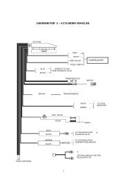
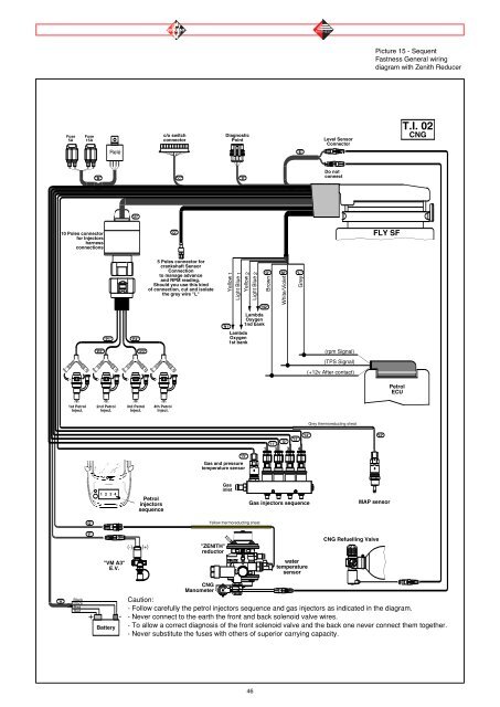
Caution:<br />
- Follow carefully the petrol injectors sequence and gas injectors as indicated in the diagram.<br />
- Never connect to the earth the front and back solenoid valve wires.<br />
- To allow a correct diagnosis <strong>of</strong> the front solenoid valve and the back one never connect them together.<br />
- Never substitute the fuses with others <strong>of</strong> superior carrying capacity.<br />
Grey<br />
Gas injectors sequence<br />
(rpm Signal)<br />
(+12v After contact)<br />
Picture 15 - Sequent<br />
Fastness General wiring<br />
diagram with Zenith Reducer<br />
Petrol<br />
ECU