Installer's handbook - 1/3 Types of installation - 2/3 Software guide ...
Installer's handbook - 1/3 Types of installation - 2/3 Software guide ...
Installer's handbook - 1/3 Types of installation - 2/3 Software guide ...

You also want an ePaper? Increase the reach of your titles
YUMPU automatically turns print PDFs into web optimized ePapers that Google loves.
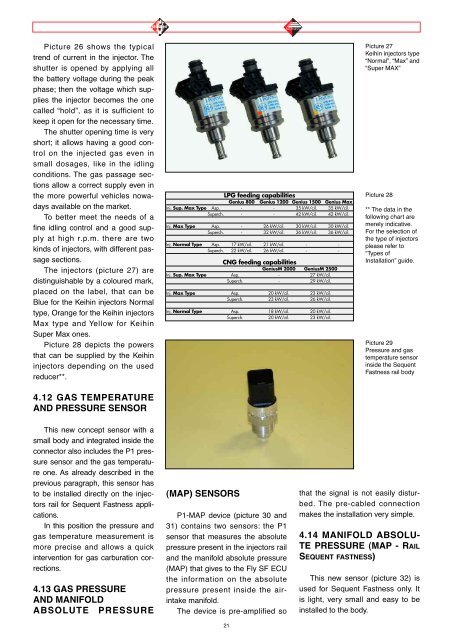
Picture 26 shows the typical<br />
trend <strong>of</strong> current in the injector. The<br />
shutter is opened by applying all<br />
the battery voltage during the peak<br />
phase; then the voltage which supplies<br />
the injector becomes the one<br />
called “hold”, as it is sufficient to<br />
keep it open for the necessary time.<br />
The shutter opening time is very<br />
short; it allows having a good control<br />
on the injected gas even in<br />
small dosages, like in the idling<br />
conditions. The gas passage sections<br />
allow a correct supply even in<br />
the more powerful vehicles nowadays<br />
available on the market.<br />
To better meet the needs <strong>of</strong> a<br />
fine idling control and a good supply<br />
at high r.p.m. there are two<br />
kinds <strong>of</strong> injectors, with different passage<br />
sections.<br />
The injectors (picture 27) are<br />
distinguishable by a coloured mark,<br />
placed on the label, that can be<br />
Blue for the Keihin injectors Normal<br />
type, Orange for the Keihin injectors<br />
Max type and Yellow for Keihin<br />
Super Max ones.<br />
Picture 28 depicts the powers<br />
that can be supplied by the Keihin<br />
injectors depending on the used<br />
reducer**.<br />
4.12 GAS TEMPERATURE<br />
AND PRESSURE SENSOR<br />
This new concept sensor with a<br />
small body and integrated inside the<br />
connector also includes the P1 pressure<br />
sensor and the gas temperature<br />
one. As already described in the<br />
previous paragraph, this sensor has<br />
to be installed directly on the injectors<br />
rail for Sequent Fastness applications.<br />
In this position the pressure and<br />
gas temperature measurement is<br />
more precise and allows a quick<br />
intervention for gas carburation corrections.<br />
4.13 GAS PRESSURE<br />
AND MANIFOLD<br />
ABSOLUTE PRESSURE<br />
LPG feeding capabilities<br />
Genius 800 Genius 1200 Genius 1500 Genius Max<br />
Inj. Sup. Max Type Asp. - - 35 kW/cil. 35 kW/cil.<br />
Superch. - - 42 kW/cil. 42 kW/cil.<br />
Inj. Max Type Asp. - 26 kW/cil. 30 kW/cil. 30 kW/cil.<br />
Superch. - 32 kW/cil. 36 kW/cil. 36 kW/cil.<br />
Inj. Normal Type Asp. 17 kW/cil. 21 kW/cil. - -<br />
Superch. 22 kW/cil. 26 kW/cil. - -<br />
CNG feeding capabilities<br />
GeniusM 2000 GeniusM 2500<br />
Inj. Sup. Max Type Asp. - 27 kW/cil.<br />
Superch. - 29 kW/cil.<br />
Inj. Max Type Asp. 20 kW/cil. 23 kW/cil.<br />
Superch. 23 kW/cil. 26 kW/cil.<br />
Inj. Normal Type Asp. 18 kW/cil. 20 kW/cil.<br />
Superch. 20 kW/cil. 23 kW/cil.<br />
(MAP) SENSORS<br />
P1-MAP device (picture 30 and<br />
31) contains two sensors: the P1<br />
sensor that measures the absolute<br />
pressure present in the injectors rail<br />
and the manifold absolute pressure<br />
(MAP) that gives to the Fly SF ECU<br />
the information on the absolute<br />
pressure present inside the airintake<br />
manifold.<br />
The device is pre-amplified so<br />
21<br />
Picture 27<br />
Keihin injectors type<br />
“Normal”, “Max” and<br />
“Super MAX”<br />
Picture 28<br />
** The data in the<br />
following chart are<br />
merely indicative.<br />
For the selection <strong>of</strong><br />
the type <strong>of</strong> injectors<br />
please refer to<br />
“<strong>Types</strong> <strong>of</strong><br />
Installation” <strong>guide</strong>.<br />
Picture 29<br />
Pressure and gas<br />
temperature sensor<br />
inside the Sequent<br />
Fastness rail body<br />
that the signal is not easily disturbed.<br />
The pre-cabled connection<br />
makes the <strong>installation</strong> very simple.<br />
4.14 MANIFOLD ABSOLU-<br />
TE PRESSURE (MAP - RAIL<br />
SEQUENT FASTNESS)<br />
This new sensor (picture 32) is<br />
used for Sequent Fastness only. It<br />
is light, very small and easy to be<br />
installed to the body.