Installer's handbook - 1/3 Types of installation - 2/3 Software guide ...
Installer's handbook - 1/3 Types of installation - 2/3 Software guide ...
Installer's handbook - 1/3 Types of installation - 2/3 Software guide ...

Create successful ePaper yourself
Turn your PDF publications into a flip-book with our unique Google optimized e-Paper software.
Pink/Black wires.<br />
Pay Attention to the fact<br />
the Spark timing function<br />
is not available for 8 cylinder<br />
vehicles ECUS.<br />
In case you use this type <strong>of</strong><br />
connection, cut and insulate the<br />
“L” grey wire indicated in the<br />
electrical plans on the “<strong>Types</strong> <strong>of</strong><br />
Installation 2/3” Guide.<br />
6.2.18.C Engine Water<br />
Temperature Signal<br />
This signal is sometimes useful<br />
to compensate the cold enrichment<br />
programmed by the carmaker that<br />
can be counterproductive in the gas<br />
operation. This kind <strong>of</strong> connection is<br />
normally for CNG applications.<br />
For its correct use it is recommended<br />
to refer to the BRC indications.<br />
The signal is taken on the<br />
wire <strong>of</strong> the engine water sensor <strong>of</strong><br />
the original equipment <strong>of</strong> the vehicle.<br />
This wire should not be cut, but<br />
only stripped and soldered with the<br />
White/Red wire <strong>of</strong> the SEQUENT<br />
Harness for Auxiliary connections<br />
(picture 12).<br />
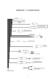
6.2.18.D Lambda<br />
Oxygen Sensor Signal<br />
In the SEQUENT system the<br />
Lambda oxygen sensor signal is<br />
not normally taken and emulated.<br />
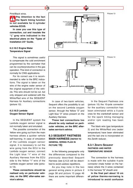
The possible connection <strong>of</strong> the<br />
Yellow wire going out from the main<br />
harness allows a quicker vehicle<br />
self-learning. In case <strong>of</strong> emulation<br />
<strong>of</strong> the Lambda oxygen sensor<br />
signal, it is necessary to cut the<br />
wire going from the ECU to the<br />
Lambda oxygen sensor, connect<br />
the Light blue “1” wire <strong>of</strong> the<br />
Auxiliary Harness from the ECU<br />
side to the Yellow “1” wire <strong>of</strong> the<br />
Lambda oxygen sensor side (picture<br />
13).<br />
These connections should be<br />
realised only on particular vehicles,<br />
on the BRC after-sales service’s<br />
advice.<br />
Petrol<br />
ECU<br />
10-pole-harness<br />
connector<br />
for auxiliary<br />
connections<br />
Oxygen sensor signal<br />
Yellow 1<br />
Light blue 1<br />
In case <strong>of</strong> two-bank vehicles,<br />
Sequent <strong>of</strong>fers the possibility to act<br />
on the second Lambda oxygen<br />
sensor, through the Yellow “2” and<br />
Light blue “2” wires present on the<br />
Auxiliary Harness.<br />
These last connections too<br />
should be only realised on particular<br />
vehicles, on the BRC aftersales<br />
service’s advice.<br />
6.3 SEQUENT FASTNESS<br />
MAIN HARNESS (REFER TO<br />
GENERAL WIRING PLAN IN<br />
PICTURE 15)<br />
"N1"<br />
In the following paragraphs only<br />
the differences compared to the<br />
previously described Sequent<br />
Harness (see § 6.2) will be described<br />
to avoid useless repetitions.<br />
As you may note in the two<br />
general wiring plans in picture 2<br />
page 38 and picture 15 page 46<br />
there are some important differences.<br />
45<br />
N1<br />
✂<br />
Yellow 2<br />
Light blue 1<br />
Light blue 2<br />
N2<br />
"Q"<br />
✂<br />
"N2"<br />
Yellow 1<br />
"N"<br />
Oxygen sensor signal<br />
Petrol<br />
ECU<br />
FLY SF<br />
FLY SF<br />
Picture 13<br />
Picture 14<br />
In the Sequent Fastness one<br />
(picture 15) the 10-pole connector<br />
for the auxiliary connection has<br />
been eliminated while a 5-pole<br />
ones for the crankshaft sensor and<br />
for the spark timing managing<br />
and/or rpm reading has been<br />
added.<br />
The black wire (gas temperature<br />
2) and the White/Red one (water<br />
temperature) have been eliminated<br />
and the last one is incorporated on<br />
the Zenith reducer.<br />
6.3.1 ZENITH SEQUENT<br />
FASTNESS AND WATER<br />
TEMPERATURE SENSOR<br />
The connection to the harness<br />
is made with the suitable 4-pole<br />
connector (male holder on the harness)<br />
where the 3 wires contained<br />
in the harness “G” sheath end.<br />
In the final part about 10 cm<br />
<strong>of</strong> yellow thermo-narrowing is<br />
introduced to avoid confusion