Installer's handbook - 1/3 Types of installation - 2/3 Software guide ...
Installer's handbook - 1/3 Types of installation - 2/3 Software guide ...
Installer's handbook - 1/3 Types of installation - 2/3 Software guide ...

Create successful ePaper yourself
Turn your PDF publications into a flip-book with our unique Google optimized e-Paper software.
everything). If available, use always<br />
the suitable fixing bracket.<br />
Avoid too hot areas or subjected<br />
to high thermal radiation. Even<br />
though the ECU is waterpro<strong>of</strong>,<br />
avoid installing it in areas subjected<br />
to continuos dripping water in case<br />
<strong>of</strong> rain, so that the water does not<br />
penetrate and stagnate in the harness<br />
or sheaths.<br />
No adjustment is programmed<br />
on the ECU; it is therefore not<br />
important it is easily accessible. It is<br />
more important, instead, that the<br />
cable going from the ECU with the<br />
computer connection is placed in a<br />
very accessible area and protected<br />
by the cap from possible water infiltration.<br />
5.13 CHANGE-OVER<br />
SWITCH<br />
Choose an easily accessible<br />
and visible place for the driver and<br />
fix the device with the screws supplied.<br />
Substituting the label with the<br />
spare one, the changeover switch<br />
can also be installed in vertical<br />
position. Eliminating the external<br />
body, the changeover switch can be<br />
directly built in the vehicle’s dashboard<br />
using the special tool to drill,<br />
code 90AV99000043.<br />
Specific built-in changeover<br />
switches are also available for<br />
every single vehicle; they are to be<br />
positioned in place <strong>of</strong> the original<br />
switch-cover plates. Please refer to<br />
the price list in force to know the<br />
available models.<br />
Make anyway sure it is always a<br />
specific changeover switch in the<br />
two-position version with buzzer.<br />
5.14 HARNESS<br />
The harness <strong>of</strong> the Sequent<br />
system guarantees the correct transmission<br />
<strong>of</strong> every inlet and outlet<br />
signal <strong>of</strong> the ECU. From a “mechanical”<br />
point <strong>of</strong> view, it is recommended<br />
to place the harness very carefully<br />
and to avoid forcing on the<br />
connections (never pull the wires to<br />
let the connector go through a hole<br />
or to disconnect it!!!). Avoid making<br />
too remarked folds, too strong<br />
clamping, sliding against moving<br />
parts, etc. Avoid certain pieces <strong>of</strong><br />
wires from being too stretched<br />
when the engine is under stress.<br />
Fix opportunely the pieces <strong>of</strong> wire<br />
near the connectors, to prevent<br />
their dangling from wearing them<br />
out in the future. Avoid any contact<br />
with sharp edges (burr the hole<br />
rims and mount some wire-leads).<br />
Avoid placing the wires <strong>of</strong> the<br />
Sequent system too close to the<br />
spark plug cables or to other parts<br />
subjected to high voltage.<br />
Each connector is polarised, for<br />
this reason it is fitted without stress<br />
only in the right direction.<br />
Important: all not pre-cabled<br />
connections should be carried out<br />
through electric brazing (s<strong>of</strong>t soldering)<br />
and opportunely insulated.<br />
The soldering should not be “cold”<br />
and should not risk coming <strong>of</strong>f in<br />
the future. Any unused wire <strong>of</strong> the<br />
harness should be shortened and<br />
separately insulated. Never use<br />
welders that are connected to the<br />
battery <strong>of</strong> the same vehicle, or welders<br />
<strong>of</strong> the quick type.<br />
5.15 INSTALLATION TYPES<br />
For various mechanical and<br />
electrical <strong>installation</strong> types, please<br />
refer to the specific <strong>handbook</strong><br />
2/3.<br />
36<br />
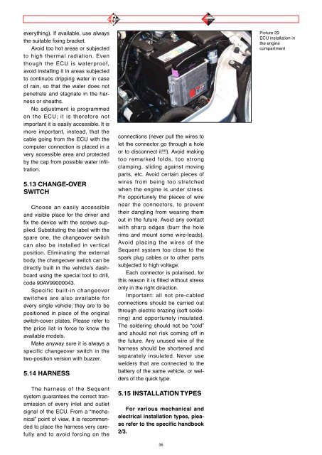
Picture 29<br />
ECU <strong>installation</strong> in<br />
the engine<br />
compartment