Installer's handbook - 1/3 Types of installation - 2/3 Software guide ...
Installer's handbook - 1/3 Types of installation - 2/3 Software guide ...
Installer's handbook - 1/3 Types of installation - 2/3 Software guide ...

You also want an ePaper? Increase the reach of your titles
YUMPU automatically turns print PDFs into web optimized ePapers that Google loves.
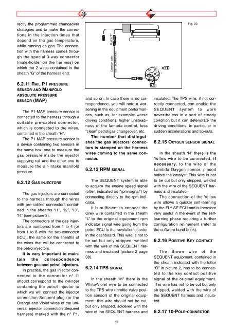
ectly the programmed changeover<br />
strategies and to make the corrections<br />
in the injection times that<br />
depend on the gas temperature,<br />
while running on gas. The connection<br />
with the harness comes through<br />
the special 3-way connector<br />
(male-holder on the harness) on<br />
which the 2 wires contained in the<br />
sheath “G” <strong>of</strong> the harness end.<br />
6.2.11 RAIL P1 PRESSURE<br />
SENSOR AND MANIFOLD<br />
ABSOLUTE PRESSURE<br />
SENSOR (MAP)<br />
The P1-MAP pressure sensor is<br />
connected to the harness through a<br />
suitable pre-cabled connector,<br />
which is connected to the wires,<br />
contained in the sheath “H”.<br />
The P1-MAP pressure sensor is<br />
a device containing two sensors in<br />
the same box: one to measure the<br />
gas pressure inside the injector<br />
supplying rail and the other one to<br />
measure the air-intake manifold<br />
pressure.<br />
6.2.12 GAS INJECTORS<br />
The gas injectors are connected<br />
to the harness through the wires<br />
with pre-cabled connectors contained<br />
in the sheaths “I1”, “I2”, “I3”,<br />
“I4” (see picture 2).<br />
The connectors <strong>of</strong> the gas injectors<br />
are numbered from 1 to 4 (or<br />
from 1 to 8 with the two-connector<br />
ECU); the same for the sheaths <strong>of</strong><br />
the wires that will be connected to<br />
the petrol injectors.<br />
It is very important to maintain<br />
the correspondence<br />
between gas and petrol injectors.<br />
In practice, the gas injector connected<br />
to the connector n° l1<br />
should correspond to the cylinder<br />
containing the petrol injector to<br />
which we will connect the injector<br />
connection Sequent plug (or the<br />
Orange and Violet wires <strong>of</strong> the universal<br />
injector connection Sequent<br />
harness) marked with the n° P1,<br />
Guaina “E”<br />
Extention cable<br />
cod. 06LB50010062<br />
and so on. In case there is no correspondence,<br />
you will note a worsening<br />
in the equipment performances,<br />
such as, for example: worse<br />
driving conditions, higher unsteadiness<br />
<strong>of</strong> the lambda control, less<br />
“clean” petrol/gas changeover, etc.<br />
The number that distinguishes<br />
the gas injectors’ connectors<br />
is stamped on the harness<br />
wires coming to the same connector.<br />
6.2.13 RPM SIGNAL<br />
The SEQUENT system is able<br />
to acquire the engine speed signal<br />
(<strong>of</strong>ten indicated as “rpm signal”) by<br />
connecting directly to the rpm indicator.<br />
It is sufficient to connect the<br />
Grey wire contained in the sheath<br />
“L” to the original equipment rpm<br />
indicator signal wire going from the<br />
petrol ECU to the revolution counter<br />
in the dashboard. This wire is not to<br />
be cut but only stripped, welded<br />
with the wire <strong>of</strong> the SEQUENT harness<br />
and insulated (picture 2 page<br />
38).<br />
6.2.14 TPS SIGNAL<br />
In the sheath “M” there is the<br />
White/Violet wire to be connected<br />
to the TPS wire (throttle valve position<br />
sensor) <strong>of</strong> the original equipment;<br />
this wire should not be cut,<br />
but only stripped, soldered with the<br />
wire <strong>of</strong> the SEQUENT harness and<br />
40<br />
(+)<br />
(-)<br />
Fig. 03<br />
insulated. The TPS wire, if not correctly<br />
connected, can enable the<br />
SEQUENT system to work<br />
nevertheless in a sort <strong>of</strong> steady<br />
condition but it can deteriorate the<br />
driving conditions, in particular in<br />
sudden accelerations and tip-outs.<br />
6.2.15 OXYGEN SENSOR SIGNAL<br />
In the sheath “N” there is the<br />
Yellow wire to be connected, if<br />
necessary, to the wire <strong>of</strong> the<br />
Lambda Oxygen sensor, placed<br />
before the catalyst. This wire is not<br />
to be cut but only stripped, welded<br />
with the wire <strong>of</strong> the SEQUENT harness<br />
and insulated.<br />
The connection <strong>of</strong> the Yellow<br />
wire allows a quicker self-learning<br />
by the FLY SF ECU and is therefore<br />
very useful in the event <strong>of</strong> the selflearning<br />
phase requiring a further<br />
configuration refinement (refer to<br />
the s<strong>of</strong>tware hand-book).<br />
6.2.16 POSITIVE KEY CONTACT<br />
The Brown wire <strong>of</strong> the<br />
SEQUENT equipment, contained in<br />
the sheath indicated with the letter<br />
“O” in picture 2, has to be connected<br />
to the key contact positive<br />
signal <strong>of</strong> the original equipment.<br />
This wire has not to be cut but only<br />
stripped, welded with the wire <strong>of</strong><br />
the SEQUENT harness and insulated.<br />
6.2.17 10-POLE-CONNECTOR