Manuale trascinatori.qxd - SMW Autoblok
Manuale trascinatori.qxd - SMW Autoblok
Manuale trascinatori.qxd - SMW Autoblok

Create successful ePaper yourself
Turn your PDF publications into a flip-book with our unique Google optimized e-Paper software.
SHAFT TURNING CHUCKS<br />
WITH RECTRACTABLE JAWS<br />
MANDRINI CON<br />
GRIFFE RETRATTILI<br />
per la lavorazione di alberi<br />
SERVICE<br />
MANUAL Page 3<br />
MANUALE<br />
OPERATIVO Pag. 11<br />
Read carefully this service manual<br />
before installation and use.<br />
Regular maintenance is the basic for<br />
correct function, high service life and<br />
precision of the SHAFT TURNING<br />
CHUCKS WITH RECTRACTABLE<br />
JAWS type GSA<br />
http://www.smwautoblok.com<br />
IMPORTANT / IMPORTANTE<br />
GSA<br />
Prima di procedere all’installazione<br />
ed all’uso, leggere attentamente<br />
questo manuale.<br />
Una corretta e regolare manutenzione<br />
è fondamentale per la funzionalità<br />
e la durata dei MANDRINI CON<br />
GRIFFE RETRATTILI - tipo GSA,<br />
per la lavorazione di alberi<br />
10705140 - IT/EN<br />
updated 31/03/2002<br />
<strong>Autoblok</strong> 2002 - Prod.Dpt.
SERVICE MANUAL<br />
CONTENTS :<br />
MANUFATURER’S DECLARATION page 4<br />
GENERAL SAFETY INSTRUCTIONS page 5<br />
DESCRIPTION page 6<br />
1. GENERAL INFORMATION AND SAFETY REGULATIONS page 7<br />
2. MOUNTING ON THE SPINDLE NOSE<br />
3. CALCULATIONS OF:<br />
page 7<br />
- MAXIMUM THRUST /DRAW-PULL page 8<br />
- STATIC GRIPPING FORCE page 8<br />
- DYNAMIC GRIPPING FORCE AND CENTRIFUGAL FORCE page 9<br />
- DRAW COUPLING page 9<br />
4. CLAMPING JAWS AND SUPPORTS<br />
5. MAINTENANCE<br />
page 9<br />
DISASSEMBLING AND ASSEMBLING INSTRUCTIONS page 18<br />
TECHNICAL DATA page 19<br />
SPARE PARTS LISTS page 20<br />
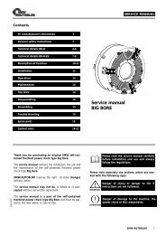
Thank you for purchasing an original<br />
<strong>SMW</strong>-AUTOBLOK GSA shaft chuck.<br />
This service manual contains the installation, the use<br />
and the maintenance instructions of the shaft chuck type<br />
GSA.<br />
<strong>SMW</strong>-AUTOBLOK reserves the right to make changes<br />
without notice.<br />
This service manual may not be - in whole or in part -<br />
copied without written agreement of <strong>SMW</strong>-AUTOBLOK.<br />
The service manual is a part of the GSA chuck<br />
and must be passed to the new owner in case of sale.<br />
<br />
SHAFT CHUCK<br />
type GSA<br />
with FACE DRIVER<br />
Please read this service manual carefully<br />
before installation and use and always<br />
follow the regulations.<br />
Please note especially the sections which are<br />
marked with the following sign:<br />
OWARNING!<br />
n Danger of injury or danger to life if<br />
instructions are not followed.<br />
n Danger of damage to the machine, the<br />
power chuck or the components, if<br />
instructions are not followed.<br />
<strong>SMW</strong>-AUTOBLOK 3
4 <strong>SMW</strong>-AUTOBLOK<br />
Manufacturer’s declaration<br />
MANUFACTURER’S DECLARATION<br />
according to machine specification 89/392/EC appendix II paragraph B<br />
<strong>SMW</strong>-AUTOBLOK S.p.a. declares that the component described as follows<br />
is completely produced in our factory and designed to be used on a machine<br />
tool. It is prohibited to install the component until it is certain that the machine<br />
in which the component will be installed, is in accordance with the regulations<br />
of the EG-rule i.d.F.91/368/EWG.<br />
Component: Shaft chuck with face driver<br />
Application: Installation in machine tool<br />
Type: GSA<br />
Applied harmonized norms: DIN EN 1550<br />
Piermauro BRONZINO<br />
Signature of person in charge
GENERAL SAFETY INSTRUCTIONS<br />
OWARNING!<br />
OWARNING!<br />
OWARNING!<br />
OWARNING!<br />
OWARNING!<br />
General safety instructions<br />
1. Correct use<br />
<strong>SMW</strong>-AUTOBLOK GSA shaft chucks are<br />
designed specially for clamping of workpieces<br />
between the centers on CNC lathes . Any other<br />
use can cause hazards. For any damages<br />
resulting herefrom <strong>SMW</strong>-AUTOBLOK is not<br />
responsible.<br />
2. Personnel<br />
GSA shaft chucks must be installed, operated<br />
and maintained only by qualified and regularly<br />
trained personnel.<br />
3. Protections<br />
During machining the power chuck and the<br />
clamped component must be protected by safety<br />
guards. Open the machine door only when<br />
machine spindle is completely stopped.<br />
Maintenance and actuation of the power chuck<br />
must only be carried out when machine spindle is<br />
stopped.<br />
4. Max. speed<br />
The max. spindle speed is only valid at max.<br />
thrust / draw-pull force ,chuck perfectly greased ,<br />
using well designed top jaws. If, for special<br />
applications, special top jaws are used, clamping<br />
force and the max. speed must be calculated<br />
according to VDI 3106 without exceeding , in any<br />
case , the max. permitted values.<br />
Heavy special top jaws , due to the centrifugal<br />
force , have a special influence on the<br />
decreasing of clamping force<br />
Warning :<br />
O.D. clamping = decreasing of clamping force<br />
The calculated values should be checked using a<br />
dynamic gripmeter type DGM.<br />
5. Remaining risks<br />
The type of components (shape, weight,<br />
unbalance, material etc.) has a big influence on<br />
the system “machine tool - GSA shaft chuck -<br />
component”. For this reason there is always a<br />
residual risk.<br />
These residual risks must be calculated by the<br />
user and have to be eliminated by suitable<br />
actions.<br />
OWARNING!<br />
OWARNING!<br />
OWARNING!<br />
6. Clamping Jaws<br />
Always use clamping Jaws according to <strong>SMW</strong>-<br />
AUTOBLOK's design, to work in safety<br />
condictions and avoid damages in the chuck.<br />
To fix the clamping Jaws use only screws class<br />
12.9, hexagon socket head cap screws .For<br />
reference , the thread should be at least 1.25 x<br />
the pitch diameter.<br />
Always tighten the screws with a torque wrench<br />
set according to the tightening moment shown in<br />
the " Use and Maintenance Manual ".<br />
If the top Jaws have higher dimensions and<br />
greater mass than the specifications issued by<br />
<strong>SMW</strong>-AUTOBLOK , the clamping force reduce<br />
accordingly and become insecure .<br />
7. Maintenance<br />
The GSA shaft chuck must be maintained in<br />
regular intervals. Check the conditions by<br />
measuring the gripping force with static<br />
gripmeter.<br />
Replace damaged parts with original <strong>SMW</strong>-<br />
AUTOBLOK spare parts only.<br />
Maintenance or checking operations must be<br />
carried out only when machine spindle is<br />
stopped. .<br />
8. Operating cylinder<br />
The GSA shaft chuck must be powered only with<br />
suitable cylinder , in accordance with the latest<br />
international regulations.<br />
NEVER provide a thrust/draw-pull force higher<br />
than the rating for each chuck model.<br />
Excess thrust/draw-pull force can cause<br />
breakage of internal parts of the chuck.<br />
If necessary reduce the thrust force accordingly.<br />
Always design connecting parts and adaptors<br />
that must work at preset thrust/draw-pull force.<br />
For any problems or questions<br />
please contact <strong>SMW</strong>-AUTOBLOK<br />
directly or one of our authorized<br />
offices.<br />
<strong>SMW</strong>-AUTOBLOK 5
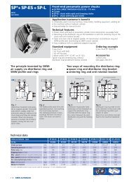
DESCRIPTION<br />
drw. 1<br />
drw. 2<br />
drw. 3<br />
6 <strong>SMW</strong>-AUTOBLOK<br />
English<br />
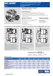
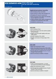
GSA chucks have compensating and retractable jaws, which make them<br />
suitable to machine shafts in one operation only.<br />
GSA chucks carry inside FD face driver . It has 4 driving pins that penetrate<br />
the shaft face for driving it .<br />
That’s for first operation .<br />
Shafts are machined in 3 stages ( see drw 3 ).<br />
Stage 1<br />
Alignment of the component between the FD face driver and the tailstock<br />
centers.<br />
The jaws are in "retractable" position ( rest position ).<br />
That’s only for first light machining of the clamping area .<br />
The shaft is driven by FD face driver only .<br />
Stage 2<br />
The 3 jaws ( moving from retracted position ) clamp on the surface that was<br />
machined in stage 1.<br />
It is possible to apply all the necessary force for heavy machining.<br />
Stage 3<br />
For finishing operation, if requested , the jaws retract "in rest position".<br />
The FD face driver only supplies the low force required.<br />
GSA chucks are available in sizes 200, 260 and 320, and can be used in<br />
a wide clamping range for various diameters.<br />
Both the special jaws and the FD face driver can be replaced easily and<br />
quickly.<br />
The component's shape and application are essential information to design<br />
the special jaws and FD face driver.<br />
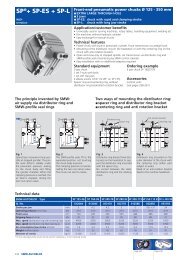
Application 1<br />
Application 2<br />
INSTRUCTIONS MANUAL<br />
Application type No. 1 (see drw 1).<br />
FD face driver with fixed center is recommended when the component's<br />
axial positioning refers to the centers.<br />
The concentricity accuracy of the face driver's and tailstock's rotating centers<br />
must be 0,01mm.<br />
The axial movement of the jaws (forwards and backwards) and of the face<br />
driver's pins is driven by a double piston hydraulic cylinder type BSN-S or<br />
DCN-S.<br />
- The cylinder's main piston drives the clamping jaws. The full piston's<br />
stroke acts as extension stroke of the jaws and as their radial stroke;<br />
the clamping stroke begins only once the extension stroke has been<br />
completed.<br />
- This special clamping system, while being compensating, gives a pulldown<br />
action. As a result, the component's surfaces are cylindric and<br />
perfectly concentric.<br />
- The second piston drives the FD face driver's pins which go towards the<br />
component with same axial force, in order to give same penetration<br />
force.<br />
BSN-S and DCN-S cylinders have an 8,5mm hole, for air or coolant flow.<br />
It is possible to mount a DEUBLIN joint in the back of the driving rod.<br />
Application type No. 2 (see drw. 2).<br />
Should the component's axial position not be determined by the centers, it<br />
is posssible to use a FD face driver with spring loaded center and compensating<br />
driving pins.<br />
Please consider that the max. concentricity accuracy of a spring loaded<br />
center is 0,02mm.<br />
This type of face driver (with spring loaded center), where only the master<br />
jaws move, we recommend a long stroke hydraulic cylinder type SIN-L.<br />
Stage 1 Stage 2
KEY<br />
= Damage risk to the chuck and / or cylinder and / or machine.<br />
= Besides damage to the chuck and the machinery RISK OF<br />
PHISICAL DAMAGE TO THE OPERATOR.<br />
1. GENERAL INFORMATION AND SAFETY REGULATIONS.<br />
<strong>SMW</strong>-AUTOBLOK automatic power chucks and hydraulic cylinders are the<br />
most advanced products on the market offering unmatched accuracy,<br />
speed, safety and reliability. The product range is the most complete and all<br />
products are manufactured in accordance with the latest international safety<br />
regulations.<br />
In this instruction manual, we have provided technical and practical<br />
information from our experience and from thousands of <strong>SMW</strong>-<strong>Autoblok</strong><br />
products users about the important safety matters of static and dynamic<br />
gripping forces, maximum speed, and clamping jaws.<br />
Please contact the closest <strong>SMW</strong>-AUTOBLOK agent for further information<br />
and assistance.<br />
1.1 MACHINE SAFETY CONDITIONS.<br />
The machines on which the chucks and the rotating cylinders are to be<br />
mounted, must include the following safety conditions:<br />
1.1.1 The chuck GSA must work inside a closed, protected zone, in order to<br />
avoid high speed release of the workpiece and any other rotating part (such<br />
as the clamping jaws or the chuck's parts).<br />
1.1.2 The machine spindle must be allowed to rotate only with the door<br />
completely closed. The door must not be opened during the working cycle.<br />
1.1.3 The machine spindle must be allowed to rotate only:<br />
A) after checking the hydraulic "feed circuit" with a pressure gauge to assure<br />
that it has reached the requested pressure.<br />
B) after the proximity switches (2pcs or more) have confirmed the position<br />
of "component clamped". A proximity signal of the 2 extreme positions<br />
(chuck jaws open or closed) must prevent rotation of the spindle.<br />
1.1.4 The electrical and hydraulic circuits of the machine MUST GUARANTEE<br />
that the chuck cannot make any opening or closing movement during<br />
rotation of the spindle.<br />
1.1.5 In case of an electric power interruption, the existing position of the<br />
chuck jaws (open or closed) must be maintained in order to avoid the<br />
possible release of the workpiece. It is necessary to use, on the hydraulic<br />
feeding, double solenoid valves with fixed positions for this purpose.<br />
1.1.6 NEVER rotate the machine spindle faster than the rpm engraved on the<br />
chuck body<br />
1.1.7 We suggest mounting a 10 bar preloaded accumulator on the hydraulic<br />
power unit. In case of a pressure drop and failure of the safety valves, it can<br />
still provide the pressure to cylinder avoiding a releasing of the part., until<br />
the machine spindle stopping .<br />
1.2 SAFETY REGULATIONS WORKING WITH GSA CHUCK AND-CYLINDER .<br />
1.2.1 The main operating characteristics and performance date are engraved on<br />
the GSA chuck body with international symbols.<br />
These characteristics are:<br />
- Maximum thrust force (Ft max)<br />
- Maximum gripping-force (SS max)<br />
- Maximum speed (N max at SS max)<br />
1.2.2 The rotating cylinder must include 2 non-return valves and 2 pressure<br />
relief valves which open automatically in case of excessive-pressure.<br />
1.2.3 The rotating cylinder must include a piston stroke control device in order<br />
to prevent rotation of the spindle if the workpiece is not clamped.<br />
1.2.4 NEVER provide a thrust force higher than the rating for each chuck<br />
model. Excess thust force can cause breakage of the internal parts of the<br />
chuck. For the calculation of the torque and the static and dynamic gripping<br />
forces carefully read and comply with the instructions of pos. 3.<br />
1.2.5 Maintainance and greasing have to be done periodically , acccording to<br />
the instruction of pos.5.<br />
1.2.6 Maintenance and cleaning MUST BE DONE WITH MACHINE OFF.<br />
1.3 SAFETY REGULATIONS FOR CLAMPING JAWS.<br />
Top jaws are a basic component for safely gripping the workpiece. It is<br />
essential to carefully read and comply with the instructions of pos. 4, 4.1 and<br />
4.2.<br />
2. MOUNTING OF THE CHUCK ON THE LATHE SPINDLE<br />
2.1 UNPACKING OF THE CHUCK.<br />
The chuck is carefully packed prior to shipment and should be safe from any<br />
damage during normal loading, transport and unloading. The external metal<br />
parts are coated with suitable rust inhibitors which must be removed before<br />
operating the chuck. This removal is best done by a light brushing with<br />
kerosene, followed by the chuck being carefully dried.<br />
2.2 HANDLING of the CHUCK:<br />
IMPORTANT: Handling of the chucks must bedone by the appropriate<br />
lifting devices.<br />
Threaded holes are located on the outside diameter of the chuck for<br />
attaching eye bolts.<br />
2.3 CHECKING THE SPINDLE NOSE.<br />
There are primarily two methods of attaching the chuck to the lathe spindle.<br />
They are standardized by the ISO 702/1 norm (mounting with short cone)<br />
and by the DIN 6353 norm (cylindrical mounting):<br />
A) Mounting with short cone ISO-A 702/1.<br />
Normally the chucks are provided with a preassembled direct mounting<br />
flange.<br />
Mounting with short cone ISO-A, the chuck can be mounted on a larger or a<br />
smaller spindle nose than the standard dimensions , by mounting on the<br />
chuck an adaptor flange.<br />
B) Mounting on the cylindrical diameter DIN 6353.<br />
Normally the chucks have standard centering diameters and mounting bolts<br />
so they can be mounted directly on the lathe spindle.<br />
Before proceeding with mounting of the chuck, it is always necessary to<br />
check carefully that the machine spindle is within the tolerances, ISO 1708,<br />
of run out (A) and side run out (B) shown in the following drawing and table.<br />
drw 4<br />
drw.4<br />
A<br />
A<br />
B B<br />
A1=2xA<br />
B1=2xB<br />
TAB.1 Ø = allowed diameter on the lathe (mm)<br />
Position Object under Permissible error<br />
measurement Ø =< 500 500
TAB.2 Ø = chuck diameter (mm)<br />
If the chuck is mounted with a special flange, it is CRITICAL that thet<br />
face of the flange is inside the centering diameter of the chuck body (where<br />
the bolts are) so that the two surfaces fit without distorting the chuck<br />
body.(see drw 6)<br />
Supporting on the external ring only causes distortion of the chuck body,<br />
blocking the movement of the internal parts, resulting in a loss of gripping<br />
force and a faster wear.<br />
TAB.3 Tighten torque for screws<br />
ø N= screws nominal diameter; M = tighten torque<br />
CLASS 8.8<br />
øNM (Nm) øNM (Nm)<br />
M5 5,7 M12 70<br />
M6 9,5 M16 170<br />
M8 23 M20 300<br />
M10 45 M24 500<br />
2.5.2 Mounting (see drw 7).<br />
Mount the cylinder flange on the lathe spindle.<br />
Screw draw bars 6 and 7 on cylinder 4<br />
Mount the GSA chuck without FD face driver and special jaws.<br />
To make assembly easier the wedge E must be fully back.<br />
Put the chuck onto the lathe spindle and screw the wedge E on draw bar 6,<br />
using a special wrench.push the GSA chuck against the adapter (previously<br />
mounted on the lathe spindle). In case of direct mounting(the adapter is<br />
already fitted on the chuck ), mount the GSA chuck on the lathe spindle.<br />
Mount the GSA chuck on the adapter, or directly on the lathe spindle,<br />
using the screws supplied.<br />
Mount the FD face driver. Check its concentricity (must be within<br />
0,005mm MAX on surface B), use the 3 centering cones C to align it.<br />
Tightening (simultaneously) the mounting bolts .Then mount the special<br />
clamping jaws.<br />
8 <strong>SMW</strong>-AUTOBLOK<br />
A<br />
1-2 mm<br />
drw.6<br />
drw.5drw<br />
5<br />
Position Object under Permissible error<br />
measurement Ø =< 160 160
K =<br />
Fs max Fs0<br />
=<br />
Ft max Ft<br />
So, at each value of Ft, corresponds a value of Fs0 (at distance "h")<br />
according to the formula:<br />
Fs0 = Ft · K<br />
Example: For a 200 GSA-3 jaw chuck we determine Fs0 for Ft = 20 kN:<br />
K =<br />
Fs max<br />
=<br />
57KN<br />
= 1,<br />
63 ⇒ Fs0 = 20 • 1,<br />
63 = 32,<br />
6KN<br />
Ft max 35KN<br />
Coefficient "K" has been determined by experiments on new power chucks,<br />
clean and properly greased with <strong>SMW</strong>-AUTOBLOK G67 grease.<br />
NOTE: The value of the static gripping force is determined at distance<br />
"h" (see drw 7). For dimensions b and h please refer to the tables at<br />
page19<br />
3.3 Dynamic gripping force and centrifugal force.<br />
Because of their design, GSA chucks strongtly compensate for the<br />
centrifugal force. Decreasing of clamping force is only due to the centrifugal<br />
force on the special top Jaws<br />
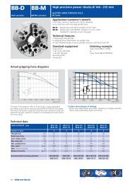
3.4 DRAW COUPLING<br />
Fsd<br />
To explain the concept of "effective draw coupling" we<br />
must begin with the "Effective dynamic gripping force"<br />
explained at point 3.3.<br />
The gripping force (Fsd) acts radially on the workpiece;<br />
to create a coupling, this must be changed into<br />
Fra "effective draw force" (Fra) which acts tangentially on<br />
the piece, multiplying it by the coefficient of friction "f".<br />
b<br />
drw.8<br />
drw 9<br />
Fra = Fsd × f<br />
We have shown below the average values of the<br />
coefficient of friction "f" for the different types of jaws<br />
and surfaces of the workpiece.<br />
TAB.5 Coefficient of friction "f":<br />
GRIPPING CONDITION Rough Worked<br />
piece piece<br />
Turned soft top jaws 0,15 0,1<br />
Hard top jaws (square teeth) 0,20 0,12<br />
Hard top jaws (sharp teeth) 0,40 0,25<br />
Jaws with carbide inserts 0,60 -<br />
The draw coupling is determined by multiplying the draw force by the arm<br />
"b" (clamping radius) (see drw 8).<br />
For machining on lathes, with a rotating piece, it is necessary to consider<br />
the "Effective dynamic draw coupling" (Tda) determined by multiplying the<br />
"Effective draw force" (Fra) by the clamping radius (b).<br />
Tda = Fra · b<br />
where: Tda [Nm] = Effective dynamic draw coupling<br />
Fra [Nm] = Effective draw force<br />
b [m] = Clamping radius<br />
Example: with a 200 GSA - 3 jaws chuck, Fsa=40 KN, in rough operation ,<br />
top jaws using carbide inserts , clamping on diameter 36mm.:<br />
Fra = Fsd · f = 40 · 0,6 = 24 kN = 24.000 N<br />
Tda = Fra · b = 24.000 · 0,018 = 432 Nm.<br />
Once the drawing coupling has been calculated, it is necessary to<br />
determine the cutting coupling (TZ), generated by the tool on the workpiece.<br />
Verify then that TZ is, at least, 2,5 times less than the Tda:<br />
Tda => 2,5 · TZ<br />
4 CLAMPING JAWS AND SUPPORTS.<br />
Unlike standard jaw chucks, where the stroke of the jaws is linear and<br />
perpendicular to the rotation axis, in GSA chucks, the clamping stroke takes<br />
place on the arch of a circle.<br />
Because of these feature, the method to make the jaws for GSA chucks is<br />
completely different compared to jaw chucks with linear guides.<br />
Next we list a serie of important suggestions on how to make the jaws<br />
correctly; for Beginners we recommend to contact our experienced <strong>SMW</strong>-<br />
AUTOBLOK engineers, who can give you useful advice.<br />
4.1 As the angular stroke is 5°, we suggest to design the clamping at 4°, see<br />
table on page 19.<br />
4.2 When designing the special jaws always check there are no interferences<br />
with the face driver FD , in clamping position or when jaws are retracted.<br />
4.3 Design the jaws as light as possible, to reduce the loss in clamping force<br />
due to the centrifugal force.<br />
4.4 As GSA are compensating chucks,it is not necessary to grind the clamping<br />
area of jaws. When possible we recommend to use hard metal inserts.<br />
4.5 The component is supported by the FD face driver, as shown in applications<br />
1 and 2.<br />
CAUTION: SEE THE FACE DRIVER’S MANUAL FOR A<br />
CORRECT USE<br />
5. MAINTENANCE<br />
Due to the fact that the GSA chuck's components operate with a constant<br />
lubrication and that the grease is not contaminated by coolant and chips, the<br />
maintenance required is minimal in comparison with standard chucks.<br />
In order to guarantee safe gripping with costant clamping force and<br />
avoid a faster wear of the chuck:<br />
- grease every 1000 chuck working hours, unscrewing the cap indicated by<br />
the words "TO GREASE" on the outside diameter of the chuck, using <strong>SMW</strong>-<br />
AUTOBLOK G67 special grease;<br />
- disassemble the chuck every 5000 working hours (following the<br />
disassembling instructions on page 18), wash out all the parts from the old<br />
grease and check their wear conditions. Use a grinding stone to remove the<br />
tribocorrosion marks, if any.<br />
Reassemble the chuck, greasing with <strong>SMW</strong>-<strong>Autoblok</strong> G67 special grease<br />
all the components.<br />
IMPORTANT:<br />
While disassembling / assembling the chuck always pay attention not to<br />
damage the O-Rings and the USIT rings that seal the internal components.<br />
When damaged please replace them (Id. nr. and types are available in the<br />
spare parts lists on page 20.<br />
Maintenance intervals at work conditions :<br />
normal / rought conditions - using coolant<br />
Measurement Lubrication Disassembling + Cleaning<br />
after operating hours 1000 / 250 5000 / 2000<br />
Special grease G67 for GSA chucks<br />
Can 1000 g<br />
Id.No. 10731224<br />
High adhesion<br />
High resistance against coolant<br />
High load bearing capacity<br />
Low friction coefficient<br />
High gripping force<br />
Avoid tribocorrosion<br />
Important for maintenance and safe operation<br />
<strong>SMW</strong>-AUTOBLOK 9
MANUALE OPERATIVO<br />
CONTENUTI :<br />
DICHIARAZIONE DEL PRODUTTORE pag. 12<br />
ISTRUZIONI GENERALI DI SICUREZZA pag. 13<br />
DESCRIZIONE pag. 14<br />
1 INFORMAZIONI GENERALI pag. 15<br />
2 MONTAGGIO DEL MANDRINO SUL NASO MACCHINA pag. 15<br />
3 CALCOLI<br />
SPINTA/TRAZIONE MASSIMA pag. 16<br />
FORZA DI SERRAGGIO STATICA pag. 16<br />
FORZA DI SERRAGGIO DINAMICA pag. 17<br />
COPPIA DI TRASCINAMENTO pag. 17<br />
4 MORSETTI DI BLOCCAGGIO ED APPOGGI pag. 17<br />
5 MANUTENZIONE<br />
SMONTAGGIO E RIMONTAGGIO pag. 18<br />
DATI TECNICI dei mandrini GSA pag. 19<br />
LISTA DELLE PARTI DI RICAMBIO pag. 20<br />
Grazie per aver acquistato un MANDRINO<br />
con GRIFFE RETRATTILI - tipo GSA originale<br />
<strong>SMW</strong>-AUTOBLOK.<br />
Questo manuale operativo contiene le istruzioni di<br />
installazione, uso e manutenzione del mandrino<br />
autocompensante tipo GSA.<br />
La <strong>SMW</strong>-AUTOBLOK si riserva il diritto di apportare dei<br />
cambiamenti tecnici senza preavviso.<br />
E’ proibito duplicare o copiare questo manuale senza<br />
autorizzazione scritta della <strong>SMW</strong>-AUTOBLOK S.p.A.<br />
Questo manuale è parte del MANDRINO tipo GSA e<br />
deve essere fornito al nuovo utilizzatore in caso di<br />
vendita.<br />
<br />
MANDRINI CON<br />
GRIFFE RETRATTILI<br />
tipo GSA<br />
Siete pregati di leggere attentamente<br />
questo manuale prima della installazione<br />
e dell’utilizzo del mandrino e di rispettare<br />
sempre le regole qui descritte.<br />
Siete pregati di fare particolare attenzione ai<br />
paragrafi preceduti dal seguente simbolo:<br />
OWARNING!<br />
n Possibilità di ferimento e/o pericolo per<br />
la vita dell’operatore se l’istruzione non<br />
è rispettata.<br />
n Possibilità di danneggiamenti o rotture<br />
alla macchina, al mandrino e/o ai<br />
componenti, se l’istruzione non è<br />
rispettata.<br />
<strong>SMW</strong>-AUTOBLOK 11
12 <strong>SMW</strong>-AUTOBLOK<br />
Dichiarazione del produttore<br />
secondo la direttiva macchine 89/392/EC appendice II paragrafo B<br />
La <strong>SMW</strong>-AUTOBLOK S.p.a. dichiara che il componente in seguito descritto<br />
è prodotto da noi internamente ed è concepito per essere montato su una<br />
macchina. E’ proibito installare il componente fino a quando non si ha la<br />
certezza che la macchina sulla quale il componente verrà montato segue la<br />
norma europea i.d.F.91/368/EWG.<br />
Componente: Mandrino autocompensante<br />
Applicazione: Installazione su una macchina utensile<br />
Tipo: GSA<br />
Norme applicate ed armonizzate: DIN EN 1550<br />
Piermauro BRONZINO<br />
Firma di un responsabile<br />
DICHIARAZIONE DEL PRODUTTORE
ISTRUZIONI GENERALI DI SICUREZZA<br />
O<br />
ATTENZIONE!<br />
O<br />
ATTENZIONE!<br />
O<br />
ATTENZIONE!<br />
O<br />
ATTENZIONE!<br />
O<br />
ATTENZIONE!<br />
Istruzioni generali di sicurezza<br />
1. Uso corretto<br />
I mandrini GSA della <strong>SMW</strong>-AUTOBLOK<br />
operano in sicurezza se sono utilizzati allo scopo<br />
per il quale sono stati progettati, ossia trascinare<br />
in rotazione pezzi in lavorazione tra le punte su<br />
torni. Altri utilizzi possono essere pericolosi.<br />
2. Personale<br />
I mandrini devono essere installati, utilizzati e la<br />
loro manutenzione deve essere effettuata da<br />
personale qualificato allo scopo.<br />
3. Protezioni<br />
Durante la lavorazione il mandrino ed il pezzo in<br />
lavorazione devono essere all’interno di una<br />
zona chiusa e protetta atta ad impedire<br />
l’espulsione di particolari soggetti a forza<br />
centrifuga. L’apertura delle porte della macchina<br />
deve poter avvenire solo con il mandrino fermo.<br />
La manutenzione e l’attuazione del mandrino<br />
devono essere effettuate solo con L’albero<br />
macchina fermo.<br />
4. Velocità massima<br />
La velocità massima del mandrino può essere<br />
raggiunta solamente se la massima forza di<br />
trazione/spinta è applicata su un mandrino ben<br />
ingrassato ed in buono stato, utilizzando per il<br />
bloccaggio dei morsetti correttamente<br />
dimensionati. Se, per applicazioni speciali,<br />
vengono utilizzati morsetti speciali , la forza di<br />
serraggio e la velocità massima raggiungibile<br />
devono essere calcolate secondo la VDI 3106,<br />
senza, in ogni caso, superare la velocità<br />
massima.<br />
Morsetti pesanti hanno particolare influenza nella<br />
diminuzione della forza di serraggio per effetto<br />
della forza centrifuga, in particolare:<br />
presa esterna = diminuzione della forza di<br />
serraggio<br />
I valori calcolati dovrebbero quindi essere<br />
verificati con un dinamometro dinamico <strong>SMW</strong>-<br />
AUTOBLOK tipo DGM.<br />
5. Rischi residui<br />
Il tipo di pezzo in lavorazione (la sua forma,<br />
peso, sbilanciamento, materiale ecc.) ha una<br />
influenza notevole sulla sicurezza del bloccaggio<br />
sul gruppo “macchina utensile - mandrino -<br />
pezzo”. Per questa ragione esistono sempre dei<br />
rischi residui. Essi devono essere tenuti presenti<br />
dall’utilizzatore, quantificati ed eliminati da azioni<br />
adeguate.<br />
O<br />
ATTENZIONE!<br />
O<br />
ATTENZIONE!<br />
O<br />
ATTENZIONE!<br />
6. Morsetti di serraggio<br />
Sempre utilizzare morsetti di presa rispondenti<br />
alle prescrizioni indicate dalla <strong>SMW</strong>-<br />
AUTOBLOK.<br />
Morsetti non rispondenti alle prescrizioni della<br />
<strong>SMW</strong>-AUTOBLOK possono causare danni al<br />
mandrino e/o incidenti.<br />
I morsetti di bloccaggio devono essere montati<br />
esclusivamente con viti a testa cilindrica con<br />
esagono incassato di classe 12.9, chiuse con<br />
l’adeguato momento di serraggio.<br />
Sempre controllare che il filetto in presa sia<br />
sufficiente (minimo 1,25 x diametro nominale<br />
della vite)!<br />
Se vengono impiegati morsetti di presa con<br />
altezza e massa superiori a quanto prescritto<br />
dalla <strong>SMW</strong>-AUTOBLOK la forza di serraggio del<br />
mandrino diminuisce in conseguenza e la presa<br />
del mandrino sul particolare in lavorazione<br />
diventa precaria.<br />
7. Manutenzione<br />
La manutenzione del mandrino deve avvenire ad<br />
intervalli regolari, controllandone inoltre sovente<br />
le condizioni, misurando la forza di serraggio con<br />
un dinamometro statico.<br />
In caso di rotture, rimpiazzare i particolari<br />
danneggiati, esclusivamente con dei particolari di<br />
ricambio originali <strong>SMW</strong>-AUTOBLOK.<br />
Ogni tipo di manutenzione e controllo deve<br />
avvenire con l’albero macchina fermo<br />
8. Cilindro di attuazione<br />
L’attuazione del mandrino deve essere effettuata<br />
esclusivamente tramite cilindri adeguati e<br />
rispondenti alle norme di sicurezza.<br />
Installando il mandrino su una macchina dotata<br />
di un cilindro verificare che esso non sia<br />
predisposto con una pressione tale per cui la<br />
forza di trazione/spinta eccede la forza di<br />
trazione/spinta massima ammessa.<br />
Se necessario ridurre la forza di trazione/spinta.<br />
I particolari di connessione e di adattamento<br />
devono essere dimensionati correttamente per<br />
sopportare un carico permanente.<br />
Per ogni ulteriore domanda<br />
riguardante la sicurezza siete<br />
pregati di contattare la <strong>SMW</strong>-<br />
AUTOBLOK direttamente o uno dei<br />
suoi agenti.<br />
<strong>SMW</strong>-AUTOBLOK 13
DESCRIZIONE<br />
14 <strong>SMW</strong>-AUTOBLOK<br />
Italiano<br />
Il mandrino GSA dispone della tecnologia delle griffe retrattili e compensanti che lo<br />
rende particolarmente adatto alla lavorazione in un’unica operazione di alberi in<br />
generale.<br />
Il mandrino GSA ospita nella parte centrale un trascinatore FD dotato una serie di<br />
4 coltelli che penetrano nel pezzo trascinandolo; questo per consentire la prima<br />
fase della lavorazione.<br />
La lavorazione dell’albero avviene in fasi successive (vds. dis.3):<br />
Fase 1 Allineamento del pezzo tra i centri del trascinatore FD e della contropunta.<br />
In questa fase le 3 griffe del mandrino sono in posizione retratta (cioè a<br />
riposo).<br />
Per consentire una prima lavorazione leggera della zona di presa il pezzo<br />
è trascinato dal solo trascinatore FD<br />
Fase 2 Le 3 griffe, dalla posizione retratta, vanno a chiudersi sulla superficie<br />
prelavorata in fase 1.<br />
E’ così possibile applicare tutta la forza necessaria alla lavorazione<br />
pesante.<br />
Fase 3 Per l’eventuale finitura completa del pezzo le griffe vengono retratte (cioè<br />
in posizione a riposo).<br />
La bassa forza di trascinamento richiesta è fornita dal solo trascinatore<br />
FD.<br />
Il mandrino GSA è disponibile nei diametri 200, 260 e 320 mm. e può essere<br />
utilizzato in un’ampia gamma di serraggio per diversi diametri.<br />
I morsetti speciali ed il trascinatore FD possono essere sostituiti facilmente e<br />
velocemente.<br />
Il tipo di applicazione e la forma del pezzo in lavorazione sono vincolanti nel<br />
progetto e nella costruzione dei morsetti speciali e del trascinatore FD.<br />
disegno 1<br />
disegno 2<br />
disegno 3<br />
Applicazione 1<br />
Applicazione 2<br />
MANUALE ISTRUZIONI<br />
Applicazione tipo 1 (vds. dis.1)<br />
Quando il posizionamento assiale del pezzo è determinato con riferimento sui<br />
centri, è preferibile utilizzare un trascinatore FD con punta fissa.<br />
La precisione di concentricità dei centri di rotazione del trascinatore e della<br />
contropunta deve essere in 0,01 mm.<br />
Il movimento assiale delle griffe (AVANTI - INDIETRO) e dei coltelli del trascinatore<br />
FD è pilotato da un cilindro idraulico a doppio pistone tipo BSN-S o DCN-S.<br />
- Il pistone principale del cilindro comanda le griffe di serraggio. La corsa<br />
completa del pistone si trasforma in corsa di estensione delle griffe e della<br />
corsa radiale di serraggio delle griffe stesse; solo dopo aver completato la<br />
corsa di estensione inizia la corsa di serraggio.<br />
La particolare configurazione del sistema di serraggio, oltre ad essere<br />
autocompensante, assicura anche un’effetto staffante; il risultato sono<br />
superfici del pezzo lavorato cilindriche e perfettamente concentriche.<br />
- Il pistone secondario comanda la spinta dei coltelli del trascinatore FD che sono<br />
spinti verso il pezzo con una uguale forza assiale in modo da generare una<br />
uguale forza di penetrazione<br />
I cilindri BSN-S e DCN-S hanno un foro centrale di 8,5 mm per il passaggio di aria<br />
o refrigerante. E’ prevista infatti l’installazione di un giunto rotante DEUBLIN nella<br />
parte posteriore dell’asta di comando.<br />
Applicazione tipo 2 (vds. dis.2)<br />
Se invece la posizione assiale del pezzo non è predeterminata dai centrini si può<br />
usare un trascinatore FD con punta caricata a molla e coltelli di trascinamento<br />
compensati.<br />
Si deve considerare inoltre che la massima precisione di concentricità di una punta<br />
caricata a molla è di 0,02 mm.<br />
Per questo tipo di trascinatore (punta caricata a molla) dove cioè sono in<br />
movimento le sole griffe con morsetti speciali, è consigliato l’uso di un cilindro<br />
idraulico con corsa lunga tipo SIN-L.<br />
Fase 1 Fase 2
Legenda<br />
= Rischio di danneggiamento al mandrino e/o al cilindro e/o alla<br />
macchina.<br />
= Oltre al danneggiamento del mandrino e del macchinario<br />
RISCHIO FISICO PER GLI OPERATORI.<br />
1. INFORMAZIONI GENERALI<br />
I mandrini <strong>SMW</strong>-AUTOBLOK, ed i relativi cilindri rotanti, sono tra i più<br />
avanzati attualmente sul mercato per precisione, velocità, sicurezza ed<br />
affidabilità. La gamma di modelli è la più completa attualmente sul mercato<br />
e dispone dei più avanzati requisiti di sicurezza richiesti dalle norme<br />
internazionali.<br />
Per le rilevanti problematiche della sicurezza, delle forze di bloccaggio<br />
statiche e dinamiche, delle velocità di rotazione, dei morsetti di bloccaggio e<br />
della manutenzione, abbiamo dato indicazioni tecniche e pratiche derivate<br />
dalla nostra esperienza e da quella di migliaia di utilizzatori di prodotti <strong>SMW</strong>-<br />
AUTOBLOK.<br />
Vi preghiamo di contattare l'agente <strong>SMW</strong>-AUTOBLOK più vicino per ulteriori<br />
informazioni.<br />
1.1 NORME DI SICUREZZA SULLA MACCHINA.<br />
Le macchine sulle quali vanno montati gli autocentranti, ed i relativi cilindri,<br />
devono possedere le seguenti norme di sicurezza:<br />
1.1.1 Il mandrino GSA deve essere contenuto all'interno di una zona di lavoro<br />
chiusa con protezioni adeguate ad impedire l'espulsione di elementi in<br />
rotazione (come il pezzo, i morsetti di bloccaggio ed i particolari del<br />
mandrino GSA).<br />
1.1.2 La macchina deve ruotare solo con la porta completamente chiusa. La<br />
porta non deve poter essere aperta durante il ciclo di lavorazione.<br />
1.1.3 La macchina deve ruotare solo dopo:<br />
A) Il controllo a mezzo di un pressostato del raggiungimento nel circuito di<br />
alimentazione della pressione prefissata.<br />
B) Il controllo a mezzo di 2 o più interruttori di prossimità della posizione di<br />
pezzo bloccato. Un controllo sulle 2 posizioni estreme anteriore e posteriore<br />
del cilindro (mandrino GSA tutto aperto o chiuso) deve quindi inibire la<br />
rotazione.<br />
1.1.4 I circuiti elettrici ed idraulici della macchina devono essere configurati in<br />
modo da escludere la possibilità di apertura e chiusura delle griffe durante<br />
la rotazione dell'albero.<br />
1.1.5 Nel caso di caduta e successivo ritorno della alimentazione elettrica, la<br />
posizione di comando esistente (bloccaggio o sbloccaggio) non deve<br />
variare (provocando eventualmente l'apertura del mandrino GSA); è quindi<br />
necessario utilizzare elettrovalvole a 2 solenoidi con posizioni fisse.<br />
1.1.6 La macchina non deve MAI ruotare ad una velocità superiore a quella<br />
incisa sul mandrino GSA.<br />
1.1.7 Si consiglia di montare sul circuito idraulico un accumulatore precaricato<br />
a 10-20 bar che, in caso di mancanza della pressione e non funzionamento<br />
delle valvole di sicurezza continui a fornire la pressione al cilindro,<br />
bloccando il pezzo fino all'arresto dell'albero.<br />
1.2 NORME DI SICUREZZA PER L'UTILIZZO DEL GRUPPO MANDRINO<br />
GSA-CILINDRO.<br />
1.2.1 Il mandrino GSA ha incisi sul corpo ed espressi con simbologia<br />
internazionalmente comprensibile i dati principali di utilizzo:<br />
- Spinta massima (Ft max)<br />
- Forza di bloccaggio massima (SS max)<br />
- Velocità massima (N max at SS max)<br />
1.2.2 Il cilindro rotante deve avere 2 valvole di non ritorno e 2 valvole di<br />
massima pressione tarate in modo da scaricare sovrapressioni anomale.<br />
1.2.3 Il cilindro rotante deve avere un dispositivo di controllo della corsa del<br />
pistone per evitare la rotazione del mandrino con pezzo non bloccato<br />
1.2.4 Assicurarsi di MAI applicare una trazione/spinta al tirante superiore a<br />
quella massima consentita sul mandrino GSA. Per determinare la coppia di<br />
trascinamento e le forze di bloccaggio statiche e dinamiche, leggere<br />
attentamente ed applicare le prescrizioni del punto 3.<br />
1.2.5 E' indispensabile provvedere alla manutenzione e all'ingrassaggio<br />
periodici del mandrino GSA secondo le prescrizioni del punto 5.<br />
1.2.6 Tutte le operazioni sul mandrino GSA devono ESSERE ESEGUITE A<br />
MACCHINA SPENTA.<br />
1.3 NORME DI SICUREZZA<br />
BLOCCAGGIO.<br />
PER L'UTILIZZO DEI MORSETTI DI<br />
I morsetti sono un elemento fondamentale per la sicurezza del bloccaggio;<br />
è pertanto indispensabile leggere attentamente e seguire tutte le<br />
prescrizioni dei punti 4, 4.1 e 4.2.<br />
2. MONTAGGIO DEL MANDRINO GSA SULLA MACCHINA.<br />
2.1 DISIMBALLAGGIO DEL MANDRINO GSA.<br />
Il mandrino GSA è fornito accuratamente imballato e protetto da eventuali<br />
urti dovuti ad una normale manipolazione per carico, trasporto e scarico. Le<br />
parti metalliche esterne, soggette a rischio di ossidazione, sono coperte da<br />
un idoneo antiossidante protettivo che, all'atto della messa in servizio, va<br />
accuratamente asportato, utilizzando un pennello imbevuto di kerosene;<br />
dopo questa pulitura, asciugare il mandrino GSA.<br />
2.2 MANIPOLAZIONE DEL MANDRINO GSA.<br />
IMPORTANTE: Manipolare i mandrini GSA solo con appositi apparecchi<br />
di sollevamento.<br />
Sul diametro esterno di tutti i mandrini GSA vi sono fori filettati per il<br />
fissaggio di golfari.<br />
2.3 CONTROLLO DEL NASO MACCHINA.<br />
I sistemi di fissaggio del mandrino GSA sul naso macchina sono<br />
essenzialmente di 2 tipi e sono normalizzati dalla norma ISO 702/I (attacco<br />
a cono corto) e dalla norma DIN 6353 (attacco cilindrico).<br />
A) Montaggio su cono corto ISO-A 702/I.<br />
Normalmente i mandrini GSA vengono forniti con la flangia di attacco diretto<br />
montata.<br />
Con il cono corto ISO-A, il mandrino GSA può essere montato su un naso<br />
macchina di dimensione inferiore o superiore a quello standard, montando<br />
una flangia di adattamento.<br />
B) Montaggio su diametro cilindrico DIN 6353.<br />
Normalmente gli autocentranti hanno i diametri di centraggio e le viti di<br />
fissaggio normalizzati e si montano direttamente sul naso macchina.<br />
Prima di procedere al montaggio del mandrino GSA è sempre necessario<br />
verificare che il naso macchina sia nelle tolleranze di rotondità (A) e<br />
planarità (B) previste dalla norma ISO 1708 (fig. X e Y) sotto riportate:<br />
disegno<br />
drw.4<br />
4<br />
A<br />
TAB.1 Ø = diametro ammesso sul tornio (mm)<br />
A<br />
B B<br />
A1=2xA<br />
B1=2xB<br />
Posizione Oggetto della Errore ammesso<br />
misurazione Ø =< 500 500
TAB.2 Øa = diametro autocentrante (mm)<br />
Posizione Oggetto della Errore ammesso<br />
misurazione Ø =< 160 160
Fs max Fs0<br />
K = =<br />
Ft max Ft<br />
Per cui, ad ogni Ft, corrisponde un valore di Fs0 (alla distanza "h") secondo<br />
la formula:<br />
Fs0 = Ft · K<br />
Esempio: Per un mandrino 200 GSA vogliamo determinare Fso per Ft = 20<br />
kN.<br />
K =<br />
Fs max<br />
=<br />
57KN<br />
= 1,<br />
63 ⇒ Fs0 = 20 • 1,<br />
63 = 32,<br />
6KN<br />
Ft max 35KN<br />
Il coefficiente K è stato determinato sperimentalmente su autocentranti<br />
nuovi, ed adeguatamente ingrassati con grasso specifico <strong>SMW</strong>-<br />
AUTOBLOK G67.<br />
N.B.: Il valore della forza di serraggio statica viene dato alla distanza<br />
"h" (vedi dis.7). Per le quote h e b fare riferimento alle tabelle pag. 19.<br />
3.3 FORZA DI SERRAGGIO DINAMICA.<br />
L’esclusiva geometria costruttiva dei mandrini GSA fà sì che la forza<br />
centrifuga che agisce sulle griffe-base non influenzi in modo significativo la<br />
forza di serraggio; la diminizione della forza di serraggio stessa sarà dovuta<br />
quindi solo alla forza centrifuga dei morsetti speciali.<br />
3.4 COPPIA DI TRASCINAMENTO<br />
Per chiarire il concetto di "Coppia di trascinamento<br />
effettiva", partiamo dalla "Forza di serraggio dinamica<br />
Fsd effettiva" trattata al punto 3.3.<br />
La forza di serraggio, agente radialmente sul pezzo,<br />
per creare una coppia, deve essere trasformata in<br />
"Forza di trascinamento effettiva" (Fra), tangenziale,<br />
Fra moltiplicandola per il coefficiente di attrito "f".<br />
b<br />
drw.8<br />
disegno 9<br />
Fra = Fsd * f<br />
Qui di seguito indichiamo a valori medi del coefficiente<br />
di attrito "f" per i diversi tipi di morsetti di bloccaggio e<br />
di superfici del pezzo.<br />
TAB.5 - Coefficiente di attrito "f":<br />
CONDIZIONI DI PRESA Pezzo Pezzo<br />
grezzo lavorato<br />
Morsetti teneri torniti 0,15 0,1<br />
Morsetti duri (denti quadri) 0,20 0,12<br />
Morsetti duri (denti a punta) 0,40 0,25<br />
Morsetti con inserti in carburo 0,60 -<br />
La coppia di trascinamento è determinata dal prodotto della forza di<br />
trascinamento per il braccio b (raggio di bloccaggio) (vedi dis. 8).<br />
Per le lavorazioni su torni, con pezzo in rotazione, è necessario considerare<br />
la "Coppia di trascinamento dinamica effettiva" (Tda), che viene determinata<br />
dal prodotto della "Forza di trascinamento effettiva" (Fra) per il raggio (b):<br />
Tda = Fra · b<br />
in cui: Tda [Nm] = Coppia di trascinamento dinamica effettiva<br />
Fra [N] = Forza di trascinamento dinamica effettiva<br />
b [m] = Raggio di bloccaggio<br />
Esempio: con un mandrino 200 GSA, con Fsd=40 kN, in operazione di<br />
sgrossatura, presa con inserti in carburo, bloccaggio su diametro 36mm:<br />
Fra = Fsd · f = 40 · 0,6 = 24 kN = 24.000 N<br />
Tda = Fra · b = 24000 · 0,018 = 432 Nm.<br />
Calcolata la Tda è necessario determinare la "Coppia di taglio" (TZ)<br />
generata dalla lavorazione degli utensili sul pezzo<br />
Verificare quindi che TZ sia almeno 2,5 volte inferiore a Tda ossia:<br />
Tda => 2,5 · TZ<br />
4. MORSETTI DI BLOCCAGGIO ED APPOGGI<br />
A differenza dei mandrini normali, dove la corsa dei morsetti è lineare e<br />
ortogonale all'asse di rotazione, nei mandrini GSA la corsa avviene su un<br />
arco di cerchio.<br />
In conseguenza di questa caratteristica, la tecnica di costruzione dei<br />
morsetti dei mandrini GSA è diversa rispetto ai morsetti dei mandrini a griffe<br />
con guide lineari.<br />
Elenchiamo qui di seguito una serie di consigli indispensabili per la corretta<br />
costruzione dei morsetti di bloccaggio, e consigliamo per le prime<br />
applicazioni di sottoporre le soluzioni alla visione dei tecnici specializzati<br />
<strong>SMW</strong>-<strong>Autoblok</strong>.<br />
4.1 La corsa angolare totale delle griffe è di 5°; si consiglia di fase la posizione<br />
nominale di bloccaggio a 4° (vedere tabella di caratteristiche a pag. 19).<br />
4.2 Nella progettazione dei morsetti assicurarsi sempre che gli stessi non<br />
vadano ad interferire con il trascinatore FD sia nella posizione di serraggio<br />
che in quella retratta (vedere fig.3).<br />
4.3 Compatibilmente con le esigenze di resistenza costruire i morsetti il più<br />
leggeri possibile per ridurre la perdita di forza di serraggio per effetto della<br />
forza centrifuga.<br />
4.4 Poichè il mandrino GSA è autocompensante non è nessaria la rettifica delle<br />
zone di presa-pezzo dei morsetti, anzi si consiglia di usare SEMPRE,<br />
quando ciò è possibile, gli inserti in metallo duro.<br />
4.5 L’appoggio del pezzo è ovviamente fatto sul trascinatore FD come indicato<br />
negli schemi di applicazione 1 e 2.<br />
ATTENZIONE: PER IL CORRETTO UTILIZZO VEDERE LO<br />
SPECIFICO MANUALE DEL TRASCINATORE FD<br />
5. MANUTENZIONE<br />
Considerato che i mandrini GSA operano con costante lubrificazione, e che<br />
il grasso non é contaminato da refrigerante e trucioli, la manutenzione<br />
richiesta é minima in confronto ai mandrini standard a griffe radiali.<br />
Per garantire un bloccaggio sicuro e per impedire un'usura prematura<br />
dei particolari interni del mandrino:<br />
- ingrassare con grasso speciale <strong>SMW</strong>-<strong>Autoblok</strong> G67, ogni 1000 ore<br />
lavorative i particolari interni, svitando il tappo indicato da "TO GREASE"<br />
sulla circonferenza esterna del mandrino;<br />
- smontare il mandrino ogni 5000 ore lavorative (seguendo le istruzioni di<br />
smontaggio di pag. 18), lavare via dai particolari interni il grasso vecchio,<br />
controllare le condizioni di usura e togliere eventuali tracce di<br />
tribocorrosione con una pietra abrasiva.<br />
Rimontare il mandrino, ingrassando con grasso speciale <strong>SMW</strong>-<strong>Autoblok</strong><br />
G67 tutti i particolari.<br />
IMPORTANTE:<br />
Durante le operazioni di smontaggio / rimontaggio del mandrino porre<br />
particolare attenzione a non danneggiare le guarnizioni O-Rings e gli anelli<br />
USIT. In caso di danneggiamenti è tassativo sostituirle (le matricole dei<br />
ricambi sono specilficate alla pag. 20).<br />
Intervalli di manutenzione in condizioni di lavoro :<br />
normale / difficili ed uso di refrigerante<br />
Misurazione Lubrificazione Smontaggio + Pulizia INT<br />
Ore di lavoro 1000 / 250 5000 / 2000<br />
Grasso speciale G67 per mandrini<br />
stagni a serraggio automatico.<br />
Latta 1000 g<br />
Cod. 10731224<br />
Aderenza molto elevata al metallo<br />
Alta resistenza al refrigerante=intervalli di<br />
ingrassaggio più lunghi<br />
Diminuzione del coefficiente di attrito nel<br />
meccanismo interno = maggiore forza di<br />
serraggio<br />
Evita la tribo-corrosione<br />
Importante per la manutenzione e la sicurezza<br />
<strong>SMW</strong>-AUTOBLOK 17
DISASSEMBLING<br />
1) Remove the clamping jaws and the FD face driver.<br />
2) Reduce the pressure in the hydraulic cylinder to 10 bar. Position the<br />
piston (or pistons) at the middle of the stroke.<br />
3) Unscrew the internal draw bar.<br />
4) Remove the GSA chuck from the external draw bar using the wrench<br />
on the bushing "15".<br />
5) Uncrew fixing bolts "44" and remove the GSA chuck from the<br />
machine.<br />
6) Unscrew the bolts “25" and remove the flange "2".<br />
7) Pull out the central unit ("3" and "4") and the jaws "5"<br />
8) Unscrew bolt "28", remove the stop dowel "18" and pull out the pins<br />
"10" and "11".<br />
CAUTION: To replace a component of the wedge unit should it<br />
be damaged or too worn out ("3" "4" "12" and "14"), unscrew<br />
bushing "15" from the wedge "4".<br />
This operation might be difficult because the unit is assembled with<br />
special paste (Loctite).<br />
9) Unscrew bolts "30" ; dismount cover "6" and bushing "7".<br />
10) Clean the components. Replace the damaged ones, including the<br />
seals, if necessary<br />
<br />
<br />
CAUTION: USE ORIGINAL <strong>SMW</strong> - AUTOBLOK<br />
SPARE PARTS ONLY<br />
CAUTION: While disassembling / assembling the chuck always<br />
pay attention not to damage the O-Rings and the USIT rings that<br />
seal the internal components. When damaged please substitute<br />
them (Id. nr. and types are available in the spare parts lists).<br />
REASSEMBLING<br />
1) Reassemble the components in reverse order of dismantling cycle.<br />
Plentifully grease the components , using <strong>SMW</strong>-<strong>Autoblok</strong> G67<br />
grease.<br />
18 <strong>SMW</strong>-AUTOBLOK<br />
DISASSEMBLING and REASSEMBLING of GSA chucks<br />
SMONTAGGIO e RIMONTAGGIO di mandrini GSA<br />
SMONTAGGIO<br />
1) Smontare i morsetti riportati ed il trascinatore FD.<br />
2) Abbassare la pressione nel cilindro idraulico a circa 10 bar e portare i<br />
pistoni (od il pistone) in un punto intermedio della loro corsa.<br />
3) Svitare il tirante interno.<br />
4) Scollegare il mandrino GSA dal tirante esterno agendo con l’apposita<br />
chiave sulla boccola part.15.<br />
5) Svitare le viti di fissaggio part.44 e smontare il mandrino GSA dalla<br />
macchina.<br />
6) Svitare le viti part.25 e togliere la flangia base part.2.<br />
7) Sfilare tutto il gruppo centrale (part.3 e 4) e le griffe part.5.<br />
8) Svitare la vite part.28, togliere la rosetta di fermo part.18 e sfilare i<br />
perni part.10 e 11.<br />
ATTENZIONE: se qualche particolare del gruppo manicotto<br />
(part.3, 4, 12 e 14) risulta danneggiato od eccessivamente usurato,<br />
per poterlo sostituire occorre svitare la boccola part.15 dal manicotto<br />
part.4.<br />
Poichè il gruppo è incollato con frena-filetti l’operazione richiede l’applicazione<br />
di un notevole sforzo.<br />
9) Svitare le viti part.30 e smontare il coperchio part.6 e la boccola<br />
part.7.<br />
10) Eseguire la normale pulizia, sostituire i particolari eventualmente danneggiati<br />
e sostituire, se necessario, le guarnizioni<br />
<br />
<br />
ATTENZIONE: UTILIZZARE SEMPRE E SOLAMENTE<br />
RICAMBI ORIGINALI <strong>SMW</strong> - AUTOBLOK.<br />
ATTENZIONE: Durante lo smontaggio ed il rimontaggio del<br />
mandrino GSA fare attenzione a non perdere o danneggiare le<br />
guarnizioni e le rondelle USIT. Quando necessario, sostituirle<br />
(codici e tipi sono a disposizione nelle parti di ricambio).<br />
RIMONTAGGIO<br />
1) Riassemblare tutti i particolari seguendo l’ordine inverso del ciclo di<br />
SMONTAGGIO, avendo cura di ingrassare abbondantemente i particolari<br />
con grasso <strong>SMW</strong>-AUTOBLOK G67.<br />
45
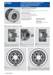
One operation shaft turning chuck with face driver Ø 200 - 320 mm<br />
Mandrini con trascinatore frontale per la lavorazione di alberi Ø 200 - 320 mm<br />
<strong>SMW</strong>-AUTOBLOK Type<br />
Modello <strong>SMW</strong>-AUTOBLOK<br />
Axial reference on the component face<br />
- spring loaded face drive<br />
- single piston cylinder (type SIN-L)<br />
Riferimento assiale sulla faccia del pezzo<br />
- trascinatore con punta a molla<br />
- cilindro singolo tipo SIN-L<br />
Subject to technical changes Soggetto a cambiamenti tecnici<br />
Axial reference on the center hole<br />
- fixed center face drive<br />
- double pistons cylinder (type BSN-S)<br />
Riferimento assiale sul foro da centro<br />
- trascinatore con punta fissa<br />
- bi-cilindro tipo BSN-S oppure DCN-S<br />
GSA 200 GSA 260 GSA 320<br />
A mm 200 260 320<br />
BF H6 mm 170 220 280<br />
C mm 146 171,4 235<br />
D mm 17 17 21<br />
E mm 50 65 75<br />
F mm M38x1,5 M50x1,5 M56x2<br />
HF mm 160 183 215<br />
Lmin mm 24 25 30<br />
Lmax mm 74 83 95<br />
R mm 60 80 102,5<br />
U gradi 5° 5° 5°<br />
W mm 18 18 18<br />
YF mm 7 7 7<br />
Zmin mm 22 25 15,4<br />
Zmax mm 81,4 92,5 93<br />
b mm 24 25 32<br />
f mm 4 5 5<br />
g mm 3 3 3<br />
j mm 48 55 65<br />
l1 mm 32 35 42<br />
l2 mm 27 32 35<br />
l3 mm 12 12,5 16<br />
m1 mm M10 M12 M16<br />
m2 mm M8 M10 M12<br />
n H7 mm 12,68 12,68 12,68<br />
o h7 mm 12,68 12,68 12,68<br />
ISO-A flanges for GSA chucks Flange ISO-A per mandrini GSA<br />
Type 1 - direct<br />
ISO-A mounting<br />
Tipo 1 - montaggio<br />
ISO-A diretto<br />
Type 2 - reduction<br />
ISO-A mounting<br />
Tipo 2 - montaggio<br />
ISO-A di riduzione<br />
Type 3 - increase<br />
ISO-A mounting<br />
Tipo 3 - montaggio<br />
ISO-A di aumento<br />
GSA chuck size Spindle Type Id. No. A BF BA C C1 T<br />
Ø mandrino GSA mandrino Tipo<br />
200 A5 2 24152050 - 170 82.563 104.8 146 24<br />
200 A6 2 24162050 - 170 106.375 133.4 146 24<br />
200 A8 3 24182050 210 170 139.719 171.4 146 40<br />
260 A6 2 24162530 - 220 106.375 133.4 171.4 24<br />
260 A8 1 24182500 - 220 139.719 171.4 - 19<br />
260 A11 3 24112510 280 2200 196.869 235 171,4 45<br />
320 A8 2 24183500 - 280 139.719 171,4 235 30<br />
320 A11 1 24113500 - 280 196.869 235 - 21<br />
<strong>SMW</strong>-AUTOBLOK 19
GSA chucks :<br />
Mandrini GSA :<br />
Spare parts list for GSA chucks<br />
Lista delle parti di ricambio dei mandrini GSA<br />
Pos. Denomination / Denominazione 200 260 320<br />
1 1 Main body / Corpo principale 21012030 21012630 21013230<br />
2 Flange / Flangia base 21302030 21302630 21303230<br />
3 Wedge / Manicotto 21022030 21022630 21023230<br />
4 Wedge rod / Gambo manicotto 21162030 21162630 21163230<br />
5 Retractable master jaw / Griffa retrattile 21032030 21032630 21033230<br />
6 Mastre jaw cover / Coperchio griffa 21102030 21102630 21103230<br />
7 Bushing / Boccola 21142030 21142630 21143230<br />
8 Lever / Biscotto 21112030 21112630 21113230<br />
9 Fulcrum washer / Spintore 99122604 99122604 99122604<br />
10 Wedge pin / Spina manicotto 21212030 21212630 21213230<br />
11 Jaws pin / Spina griffa 21192030 21192630 21193230<br />
12 Support ring / Anello di appoggio 21202030 21202630 21203230<br />
13 Support guide plate / Tassello guida 21182030 21182630 21183230<br />
14 Thkust ring / Anello spinta 21132030 21132630 21133230<br />
15 Locking ring nut / Ghiera di bloccaggio 21262030 21262630 21263130<br />
16 Fine adjusting plate / Tassello di registrazione 21462030 99462604 21463230<br />
17 Closing plug / Tappo chiusura flangia 15151130 15151130 15151330<br />
18 Stop washer / Rosetta di fermo 21152030 21152030 21153230<br />
20 Key / Linguetta 21722030 99722604 99722604<br />
25 Screw UNI59318.8 / Vite UNI5931 8.8 M12x60 M16x70 M16x80<br />
26 USIT ring / Rondella USIT U7.30x10.20x1 U7.30x10.20x1 U7.30x10.20x1<br />
27 Screw UNI5931 8.8 / Vite UNI5931 8.8 M6x10 M6x10 M6x10<br />
28 Screw UNI5931 8.8 / Vite UNI5931 8.8 M5x8 M5x8 M5x8<br />
29 Screw UNI5931 8.8 / Vite UNI5931 8.8 M6x20 M6x20 M10x25<br />
30 Screw UNI5931 12.9 / Vite UNI5931 12.9 M8x20 M8x20 M10x25<br />
31 Screw UNI5931 8.8 / Vite UNI5931 8.8 M4x10 M4x10 M4x10<br />
32 POLYPAC seal / Guarnizione POLYPAC I/GRL 0500 I/GRL 0610 I/GRL 0750<br />
33 POLYPAC seal / Guarnizione POLYPAC I/GRL 0250 I/GRL 0250 I/GRL 0250<br />
34 Screw UNI5931 8.8 / Vite UNI5931 8.8 M6x16 M8x25 M10x20<br />
35 O-Ring seal / Guarnizione O-Ring OR 2-168 OR 4950 OR 41200<br />
36 O-Ring seal / Guarnizione O-Ring OR 4143 OR 4143 OR 4143<br />
37 O-Ring seal / Guarnizione O-Ring OR 2-40 OR 2325 OR 2375<br />
38 O-Ring seal / Guarnizione O-Ring OR 3250 OR 3281 OR 3325<br />
39 Plare plug /Tappo 71628916 71628918 71628918<br />
40 POLYPAC seal / Guarnizione POLYPAC I/GRL 0480 I/GRL 0550 I/GRL 0650<br />
43 O-Ring seal / Guarnizione O-Ring OR 128 OR 128 OR 3106<br />
44 Screw UNI5931 8.8 / Vite UNI5931 8.8 M16x90 M16x100 M20x120<br />
45 Screw UNI5931 8.8 / Vite UNI5931 8.8 M6x16 M6x16 M6x20<br />
Seals Kit / Serie di guarnizioni 20542061 20542661 20543261<br />
20 <strong>SMW</strong>-AUTOBLOK<br />
45
AUTOBLOK s.p.a.<br />
10040 Caprie - Torino<br />
Tel. (0 11) 9 63 20 20 - 9 63 21 21<br />
Fax (0 11) 9 63 22 88<br />
E-mail autoblok@smwautoblok.it<br />
U.S.A.<br />
AUTOBLOK Corporation<br />
285 Egidi Drive - Wheeling, IL 60090<br />
Tel. (8 47) 2 15 - 05 91<br />
Fax (8 47) 2 15 - 05 94<br />
E-mail autoblok@smwautoblok.com<br />
Japan<br />
<strong>SMW</strong>-AUTOBLOK Japan Inc.<br />
1-5 Tamaike-Cho, Nishi-Ku<br />
Nagoya<br />
Tel. (0 52) 5 04 - 02 03<br />
Fax (0 52) 5 04 - 02 05<br />
E-mail smw-auto@alpha-web.or.jp<br />
Great Britain<br />
<strong>SMW</strong>-AUTOBLOK Workholding Ltd.<br />
8, The Metro Centre<br />
Peterborough, PE2 7UH<br />
Tel. (0 17 33) 39 43 94<br />
Fax (0 17 33) 39 43 95<br />
E-mail smw-autoblok@msn.com<br />
France<br />
AUTOBLOK S.A.R.L.<br />
17, avenue des Frères Montgolfier<br />
Z.I. Mi-Plaine - 69680 CHASSIEU<br />
Tel. 04 - 72 79 18 18<br />
Fax 04 - 72 79 18 19<br />
Internet: www.smwautoblok.fr<br />
E-mail - autoblok@smwautoblok.fr<br />
Austria<br />
<strong>SMW</strong>-AUTOBLOK<br />
Alleegasse 10<br />
A-2540 Bad Vöslau<br />
Tel./Fax (0 22 52) 7 16 08<br />
Mob. (0664) 3081908<br />
Brazil<br />
Onça-<strong>Autoblok</strong> Indústrias Metalúrgicas S/A<br />
Office: Av. Pacaembú, 904<br />
01234-950 – São Paulo – SP<br />
Plant: P.O. Box 531<br />
13270-000 – Valinhos – SP<br />
Tel. 55 (0) 19 881-1799<br />
Fax 55 (0) 19 881-1243<br />
E-mail placas@onca.com.br<br />
Germany<br />
<strong>SMW</strong>-AUTOBLOK Spannsysteme<br />
GmbH<br />
Postfach 1151 D-88070 Meckenbeuren<br />
Wiesentalstraße 28 D-88074<br />
Meckenbeuren<br />
Tel. (0 75 42) 4 05-0<br />
Fax Sales (0 75 42) 38 86<br />
Fax Export (0 75 42) 4 05-1 81<br />
E-mail smwautoblok@T-online.de<br />
W e l t w e i t i n m e h r<br />
W o r l d w i d e i n<br />
http://www.smwautoblok.com<br />
®<br />
m o r e