Service manual BIG BORE - SMW Autoblok
Service manual BIG BORE - SMW Autoblok
Service manual BIG BORE - SMW Autoblok

You also want an ePaper? Increase the reach of your titles
YUMPU automatically turns print PDFs into web optimized ePapers that Google loves.
2001-09-E<br />
Contents<br />
EC manufacturer’s declaration 2<br />
General safety instructions 3<br />
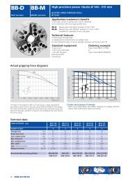
Technical details BB-N 4-63<br />
Technical details BB-N-ES 7-9<br />
Description of function 10-11<br />
Installation 12<br />
Operation 13<br />
Maintenance 14<br />
Top jaws 14<br />
Disassembling 14<br />
Assembling 15<br />
Trouble shooting 15<br />
Spare parts 15<br />
Control units 16-21<br />
Thank you for purchasing an original <strong>SMW</strong> self-contained<br />
frontend power chuck type Big Bore.<br />
This service <strong>manual</strong> contains the installation, the use and<br />
the maintenance of the self-contained frontend power<br />
chuck type Big Bore.<br />
<strong>SMW</strong>-AUTOBLOK reserves the right to make changes<br />
without notice.<br />
This service <strong>manual</strong> may not be, in whole or in part,<br />
copied without our written agreement.<br />
The service <strong>manual</strong> is a part of the self-contained<br />
frontend power chuck type Big Bore and must be passed<br />
to the new owner in case of sale.<br />
<strong>Service</strong> <strong>manual</strong><br />
<strong>BIG</strong> <strong>BORE</strong><br />
SERVICE MANUAL<br />
Please note especially the sections which are marked<br />
with the following signs:<br />
WARNING!<br />
ATTENTION!<br />
Please read the service <strong>manual</strong> carefully<br />
before installation and use and always<br />
follow the regulations.<br />
Danger of injury or danger to life if<br />
instructions are not followed.<br />
Danger of damage to the machine, the<br />
power chuck or the components.<br />
<strong>SMW</strong>-AUTOBLOK 1
2 <strong>SMW</strong>-AUTOBLOK<br />
Manufacturer’s declaration<br />
MANUFACTURER’S DECLARATON<br />
according to machine specification 89/392/EC appendix II paragraph B<br />
<strong>SMW</strong>-AUTOBLOK Spannsysteme GmbH declares that the component described following is<br />
designed for the use on a machine. It is prohibited to operated the component until it is certain<br />
that the machine in which the component is installed is in accordance with the regulations of<br />
the EC-rule i.d.F. 91/368/EWG.<br />
Important: The operation of the self-contained frontend power chuck type Big Bore is allowed<br />
only if suitable safety control units with airflow sensors, pressure gauges as well as pressure control<br />
during rotation are installed. Different from standard power chucks the jaw stroke of Big<br />
Bore air chucks is not controlled by proximity switches. The resulting remaining risks must be<br />
covered by suitable protections and covers on the machine.<br />
Component: Self-contained frontend power chuck<br />
Application: Installation in machine tool<br />
Type: Big Bore<br />
Applied harmonized norms: DIN EN 1550<br />
Signature of responsible person
General safety instructions<br />
1. Correct use<br />
<strong>SMW</strong>-AUTOBLOK self-contained frontend<br />
power chucks work safely and troublefree if<br />
WARNING! they are used according to their specification,<br />
i.e. to clamp components on the outside diameter on turning<br />
machines.<br />
Any other use can cause hazards.<br />
WARNING!<br />
2. Personnel<br />
Self-contained frontend power chucks must be<br />
installed, operated and maintained by qualified<br />
and regularly trained personnel only.<br />
3. Safety precautions<br />
During the machining process the self-contained<br />
frontend power chuck and the clamped<br />
WARNING!<br />
component must be protected by suitable<br />
safety guards mounted to the machine.<br />
The machine door must be locked closed until the machine<br />
spindle arrives to its full stop. Actuation of the power chuck<br />
must be possible at stopped spindle only! Set-up works,<br />
maintenance and all other mechanical work must be done<br />
at safe spindle stop only!<br />
WARNING!<br />
4. Technical details<br />
The max. data as max. pressure p and max.<br />
spindle speed n are engraved on the chuck<br />
body. They must not be exceeded in any case.<br />
5. Maximum speed<br />
The max. speed is only allowed at an actuating<br />
force of min. 6 bar. The jaws that are used<br />
ATTENTION!<br />
must be the corresponding hard reversible<br />
stepped jaws that radially do not exceed the chuck outside<br />
diameter. If, for special applications, special top jaws are<br />
used the clamping force and the max. speed must be calculated<br />
according to VDI 3106, but not exceeding the max.<br />
permitted speed of the chuck. Especially heavy special top<br />
jaws have a big influence on the max. speed. During the<br />
machining process the centrifugal force increases or<br />
decreases the gripping force. O.d. clamping = decreasing,<br />
i.d. clamping = increasing. All theoretically calculated<br />
values must be double checked with a suitable dynamic<br />
gripmeter. We recommend to use our dynamic gripmeter<br />
type DGM 270.<br />
6. Remaining risks<br />
The type of component (shape, weight, unbalance,<br />
material etc.) has a big influence on the<br />
ATTENTION!<br />
system machine tool - power chuck - component.<br />
For that reason there is always a residual risk. These<br />
residual risks must be calculated by the user and must be<br />
eliminated by suitable actions.<br />
GENERAL SAFETY INSTRUCTIONS<br />
7. Top jaws<br />
Always use original-<strong>SMW</strong>-AUTOBLOK-top<br />
jaws only. Jaws of other manufacturers can<br />
ATTENTION! cause damage to the chuck or accidents. Top<br />
jaws must be mounted with head socket screws of<br />
quality class 12.9 only!<br />
Tighten all mounting bolts with a specified torque. Always<br />
ensure sufficient length of the engagement (min. 1,25 x<br />
thread diameter)!<br />
If the jaw height of special jaws exceeds the height of the<br />
standard jaws the max. actuating force of the chuck must<br />
be reduced in order to avoid an excessive lever action and<br />
thus damage to the power chuck.<br />
At reduced actuating force the max. speed must also<br />
be reduced accordingly!<br />
8. Maintenance<br />
The self-contained frontend power chuck must<br />
be maintained in regular intervals according to<br />
WARNING!<br />
the specification. Check the sealness and the<br />
clamping force of both cylinder chambers with a static<br />
gripforce meter regularly.<br />
Replace damage parts with original <strong>SMW</strong>-AUTOBLOK<br />
spare parts only!<br />
Maintenance must only be carried out at safe spindle stop<br />
of the machine!<br />
The actuation of the self-contained frontend<br />
power chuck must be only be carried out by<br />
suitable safety control units with airflow sen-<br />
WARNING! sors, pressure gauges and pressure control<br />
which are in accordance with all valid safety regulations.<br />
Important: On chucks type BB-N and BB-N-ES the jaw<br />
stroke and the clamping pressure is monitored indirectly<br />
when the machine spindle is stopped and the<br />
airflow to actuate the chucks is monitored by airflow<br />
sensors and pressure gauges.<br />
After that the clamping pressure remains trapped in<br />
the cylinder chamber. During rotation of the spindle<br />
the air pressure is switched off and disconnected from<br />
the chuck! When using the safety control unit ACU-NT<br />
with the option pressure control on chuck o.d. clamping<br />
the clamping pressure in the chuck chamber for<br />
o.d. clamping can be monitored.<br />
Herefore the pressure control on the chuck must be<br />
adjusted according to the present clamping pressure<br />
used on the chuck (valid for chucks type BB-N and BB-<br />
N-ES). On the chuck type BB-N-ES the safety control<br />
unit ACU-NT with the option rapid stroke control<br />
allows to monitor that the chuck does not clamp the<br />
component on the rapid stroke (it is not allowed to<br />
clamp components on the rapid stroke!)<br />
Remaining risks must be covered by suitable actions<br />
and suitable safety guards on the machine.<br />
In case of doubts or questions please ask <strong>SMW</strong>-AUTO-<br />
BLOK or one of our authorized offices.<br />
<strong>SMW</strong>-AUTOBLOK 3
Subject to technical changes<br />
4 <strong>SMW</strong>-AUTOBLOK<br />
NEW<br />
TECHNICAL DETAILS<br />
<strong>SMW</strong>-AUTOBLOK <strong>BIG</strong> <strong>BORE</strong> BB-N 400-140 BB-N 460-181 BB-N 500-205 BB-N 500-230 BB-N 630-310 BB-N 800-410 BB-N 1000-534<br />
Id.No. 052300 052887 052318 052340 052534 052347 052650<br />
Mounting Z 310 Z 310 Z 415 Z 415 Z 510 Z 700 Z 700<br />
A mm 422 467 540 570 662 800 1000<br />
B mm 140 181 205 230 310 410 534<br />
C mm 467 467 570 570 685 850 925<br />
D H6 mm 310 310 415 415 510 700 700<br />
E mm 400 400 500 500 610 775 850<br />
Fixing bolts circle F mm 374 374 474 474 580 745 815<br />
G mm M12 M12 M12 M12 M16 M16 M16<br />
G1 mm 26 26 26 26 30 30 30<br />
H mm 196 196 225 225 263 305 332<br />
H1 mm 194 194 223 223 261 303 330<br />
J mm 8 8 8 8 8 8 10<br />
Thread circle 6x M8 / 6x UNC K mm 448 448 550 550 666 830 910<br />
L mm 20 20 20 20 20 25 33<br />
M mm 70 - 98 98 115 154 224<br />
Pneumatic connection N inch R 3/8" R 3/8" R 3/8" R 3/8" R 3/8" R 3/8" R 3/8"<br />
O mm 37 37 37 37 39,5 44,5 52,5<br />
P mm 26 26 26 26 33 33 33<br />
R mm 35 35 35 35 42 35 42<br />
S mm 374 374 474 475 575 745 815<br />
a mm 57 57 57 57 75 75 75<br />
b mm 25,5 25,5 25,5 25,5 30 30 30<br />
Serration c inch 3/32" x 90° 3/32" x 90° 3/32" x 90° 3/32" x 90° 3/32" x 90° 3/32" x 90° 3/32" x 90°<br />
Bolt DIN 912 12.9 d mm M20 M20 M20 M20 M24 M24 M24<br />
min. e mm 13 13 14 14 16 16 16<br />
T-nuts distance min./max. f mm 38/85 38/85 38/102 38/102 47/103 47/130 47/148<br />
Serration length g mm 117,5 117 138 138 142 171,5 188<br />
min./max. h mm 94,5/101,5 112/119 133,5/142 143,5/152 190,5/200,5 243/255 311/323,5<br />
α° 20 20 15 15 15 15 15<br />
β° 9 x 40 9 x 40 12 x 30 12 x 30 12 x 30 12 x 30 12 x 30<br />
γ° 37 83 60 60 60 60 60
GUB Hard reversible<br />
top jaws<br />
Gripping ranges<br />
GAB Hard top jaws<br />
Gripping ranges<br />
WBC Soft top jaws<br />
Gripping ranges<br />
TECHNICAL DETAILS<br />
Chuck BB-N 400-140 BB-N 460-181 BB-N 500-205 BB-N 500-230 BB-N 630-310 BB-N 800-410 BB-N 1000-534<br />
Jaw type GUB 500 GUB 500 GUB 500 GUB 500 GUB 630 GUB 800 GUB 800<br />
Id.No. 12085046 12085046 12085046 12085046 12086446 12088046 12088046<br />
B 55 55 55 55 75 75 75<br />
H 73 73 73 73 85 85 85<br />
L 145 145 145 145 160 220 220<br />
T 32 32 32 32 30 30 30<br />
N 25,5 25,5 25,5 25,5 30 30 30<br />
Serration 3/32" x 90° 3/32" x 90° 3/32" x 90° 3/32" x 90° 3/32" x 90° 3/32" x 90° 3/32" x 90°<br />
a 46 46 46 46 30 51 51<br />
b 38 38 38 38 50 62 62<br />
c 38 38 38 38 50 62 62<br />
kg/set 6,6 6,6 6,6 6,6 13,5 19,5 19,5<br />
A1 65-238 100-273 150-358 175-378 275-485 320-590 450-760<br />
A2 110-284 145-320 200-405 225-425 275-485 330-600 460-770<br />
A3 294-470 330-505 385-590 410-610 475-685 590-865 725-1030<br />
S 585 620 705 725 820 1050 1225<br />
Chuck BB-N 400-140 BB-N 460-181 BB-N 500-205 BB-N 500-230 BB-N 630-310 BB-N 800-410 BB-N 1000-534<br />
Jaw type GAB 500 GAB 500 GAB 500 GAB 500 GAB 630 GAB 800 GAB 800<br />
Id.No. 12085146 12085146 12085146 12085146 12086546 12089046 12089046<br />
B 55 55 55 55 75 75 75<br />
H 73 73 73 73 82 82 82<br />
L 195 195 195 195 245 320 320<br />
N 25,5 25,5 25,5 25,5 30 30 30<br />
Serration 3/32" x 90° 3/32" x 90° 3/32" x 90° 3/32" x 90° 3/32" x 90° 3/32" x 90° 3/32" x 90°<br />
a 96 96 96 96 113 165 165<br />
b 38 38 38 38 50 60 60<br />
c 38 38 38 38 50 60 60<br />
kg/set 16,5 16,5 16,5 16,5 31,5 40,5 40,5<br />
A1 25-140 60-175 50-260 70-280 105-320 95-365 225-535<br />
S 585 620 705 725 820 1010 1180<br />
Chuck BB-N 400-140 BB-N 460-181 BB-N 500-205 BB-N 500-230 BB-N 630-310 BB-N 800-410 BB-N 1000-534<br />
Jaw type WBC 500 WBC 500 WBC 500 WBC 500 WBC 630 WBC 800 WBC 800<br />
Id.No. 12075050 12075050 12075050 12075050 12076440 12078040 12078040<br />
B 60 60 60 60 80 80 80<br />
H 60 60 60 60 80 80 80<br />
L 170 170 170 170 240 320 320<br />
N 25,5 25,5 25,5 25,5 30 30 30<br />
Serration 3/32" x 90° 3/32" x 90° 3/32" x 90° 3/32" x 90° 3/32" x 90° 3/32" x 90° 3/32" x 90°<br />
a 69 69 69 69 110 165 165<br />
b 38 38 38 38 50 60 60<br />
kg/pc. 4,5 4,5 4,5 4,5 11 15 15<br />
A1 25-195 60-230 105-315 125-325 110-325 95-365 225-535<br />
S 545 580 660 680 815 1010 1180<br />
<strong>SMW</strong>-AUTOBLOK 5
WBCL Soft top jaws<br />
long version<br />
N<br />
c<br />
Gripping ranges<br />
6 <strong>SMW</strong>-AUTOBLOK<br />
TECHNICAL DETAILS<br />
Chuck BB-N 400-140 BB-N 460-181 BB-N 500-205 BB-N 500-230 BB-N 630-310 BB-N 800-410 BB-N 1000-534<br />
Jaw type WBCL 500 WBCL 500 WBCL 500 WBCL 500 WBCL 630 WBCL 800 WBCL 800<br />
Id.No. 12075140 12075140 12075140 12075140 12078040 12079040 12079040<br />
B 60 60 60 60 80 80 80<br />
H 60 60 60 60 80 80 80<br />
L 205 205 205 205 320 390 390<br />
N 25,5 25,5 25,5 25,5 30 30 30<br />
Serration 3/32" x 90° 3/32" x 90° 3/32" x 90° 3/32" x 90° 3/32" x 90° 3/32" x 90° 3/32" x 90°<br />
a 104 104 104 104 165 230 230<br />
b 38 38 38 38 60 60 60<br />
c 38 38 38 38 60 60 60<br />
kg/pc. 5,5 5,5 5,5 5,5 15 18 18<br />
A1 - 0-155 35-245 55-265 25-195 25-235 95-405<br />
S - 575 660 680 845 1020 1190<br />
NST T-nuts Chuck BB-N 400-140 BB-N 460-181 BB-N 500-205 BB-N 500-230 BB-N 630-310 BB-N 800-410 BB-N 1000-534<br />
Type NST NST NST NST NST NST NST<br />
Id.No. 12065020 12065020 12065020 12065020 13063900 13063900 13063900<br />
N 25,5 25,5 25,5 25,5 30 30 30<br />
H 34 34 34 34 44 44 44<br />
h 15 15 15 15 18 18 18<br />
G M20 M20 M20 M20 M24 M24 M24<br />
Bolt M20 x 40 M20 x 40 M20 x 40 M20 x 40 M24 x 60 M24 x 60 M24 x 60<br />
DIN 912 12.9<br />
Tighten<br />
torque 300 300 300 300 450 450 450<br />
Md max (Nm)<br />
Adapters for <strong>BIG</strong> <strong>BORE</strong> chucks<br />
ISO-A<br />
DIN 55026<br />
mounting<br />
adapters<br />
b<br />
L<br />
a<br />
B<br />
H<br />
BB-N 400-140/460-181 500-205/500-230 630-310 800-410 1000-534<br />
Spindle nose A8 A11 A15 A11 A15 A20 A11 A15 A20 A15 A20 A15 A20<br />
Id.No. 24184020 24114020 24124020 24115030 24125020 24175020 24116320 24126320 24176320 24128020 24178020 24128020 24178020<br />
A mm 46 46 46 46 46 46 56 56 56 56 56 56 56<br />
B mm 139,719 196,869 285,775 196,869 285,775 412,775 196,869 285,775 412,775 285,775 412,775 265,775 412,775<br />
C mm 171,4 235 330,2 235 330,2 463,6 235 330,2 463,6 330,2 463,6 330,2 463<br />
Bayonet and camlock flanges are available on request
Subject to technical changes<br />
NEW<br />
TECHNICAL DETAILS<br />
<strong>SMW</strong>-AUTOBLOK <strong>BIG</strong> <strong>BORE</strong> ES Type BB-N ES 400-140 BB-N ES 460-181 BB-N ES 500-205 BB-N ES 500-230 BB-N ES 630-325 BB-N ES 850-375 BB-N ES 1000-560<br />
Id.No. 052330 052838 052651 052652 052653 052654 052655<br />
Mounting Z 310 Z 310 Z 415 Z 415 Z 510 Z 700 Z 700<br />
A mm 467 467 570 570 685 850 1000<br />
B mm 140 181 205 230 325 375 560<br />
C mm 467 467 570 570 685 850 925<br />
D H6 mm 310 310 415 415 510 700 700<br />
E mm 400 400 500 500 610 775 850<br />
Fixing bolts circle F mm 374 374 474 474 580 745 815<br />
G mm M12 M12 M12 M12 M16 M16 M16<br />
G1 mm 26 26 26 26 30 30 30<br />
H mm 240 240 282 282 307,5 354 332<br />
H1 mm 238 238 280 280 305,5 352 330<br />
J mm 8 8 8 8 8 8 10<br />
Thread circle 6x M8 / 6x UNC K mm 448 448 550 550 666 830 910<br />
L mm 20 20 20 20 20 25 33<br />
M mm - - - - - - 224<br />
Pneumatic connection N inch R 3/8" R 3/8" R 3/8" R 3/8" R 3/8" R 3/8" R 3/8"<br />
O mm 37 37 37 37 39,5 44,5 52,5<br />
P mm 26 26 26 26 33 33 33<br />
R mm 35 35 35 35 42 35 42<br />
S mm 374 374 474 474 575 745 815<br />
T mm 35 35 35 35 35 35 35<br />
U mm 374 374 474 474 580 745 905<br />
a mm 57 57 57 57 75 75 75<br />
b mm 25,5 25,5 25,5 25,5 30 30 30<br />
Serration c inch 3/32" x 90° 3/32" x 90° 3/32" x 90° 3/32" x 90° 3/32" x 90° 3/32" x 90° 3/32" x 90°<br />
Bolt DIN 912 12.9 d mm M20 M20 M20 M20 M24 M24 M24<br />
min. e mm 14 14 14 14 16 16 16<br />
T-nuts distance min./max. f mm 38/90 38/75 38/104 38/92 47/100 47/140 47/125<br />
Serration length g mm 121 106 140 127,5 138 182 166<br />
min./max. h mm 124 141,5 170 182,5 230 268 360<br />
α° 20 20 15 15 15 15 15<br />
β° 9 x 40 9 x 40 12 x 30 12 x 30 12 x 30 12 x 30 12 x 30<br />
γ° 83 83 60 60 60 60 60<br />
<strong>SMW</strong>-AUTOBLOK 7
GUB Hard reversible<br />
top jaws<br />
Gripping ranges<br />
8 <strong>SMW</strong>-AUTOBLOK<br />
TECHNICAL DETAILS<br />
Chuck BB-N ES 400-140 BB-N ES 460-181 BB-N ES 500-205 BB-N ES 500-230 BB-N ES 630-325 BB-N ES 850-375 BB-N ES1000-560<br />
Jaw type GUB 500 GUB 500 GUB 500 GUB 500 GUB 630 GUB 800 GUB 800<br />
Id.No. 12085046 12085046 12085046 12085046 12086446 12088046 12088046<br />
B 55 55 55 55 75 75 75<br />
H 73 73 73 73 85 85 85<br />
L 145 145 145 145 160 220 220<br />
T 32 32 32 32 30 30 30<br />
N 25,5 25,5 25,5 25,5 30 30 30<br />
Serration 3/32" x 90° 3/32" x 90° 3/32" x 90° 3/32" x 90° 3/32" x 90° 3/32" x 90° 3/32" x 90°<br />
a 46 46 46 46 30 51 51<br />
b 38 38 38 38 50 62 62<br />
c 38 38 38 38 50 62 62<br />
kg/set 6,6 6,6 6,6 6,6 13,5 19,5 19,5<br />
A1 78-264 113-270 175-388 200-388 295-500 320-610 470-760<br />
A2 125-310 160-315 225-435 250-435 295-500 330-620 480-770<br />
A3 310-495 345-500 410-620 435-620 495-700 590-865 745-1030<br />
S 635 640 765 765 870 1070 1250<br />
GAB Hard top jaws Chuck BB-N ES 400-140 BB-N ES 460-181 BB-N ES 500-205 BB-N ES 500-230 BB-N ES 630-325 BB-N ES 850-375 BB-N ES1000-560<br />
Jaw type GAB 500 GAB 500 GAB 500 GAB 500 GAB 630 GAB 800 GAB 800<br />
Id.No. 12085146 12085146 12085146 12085146 12086546 12089046 12089046<br />
B 55 55 55 55 75 75 75<br />
H 73 73 73 73 82 82 82<br />
L 195 195 195 195 245 320 320<br />
N 25,5 25,5 25,5 25,5 30 30 30<br />
Serration 3/32" x 90° 3/32" x 90° 3/32" x 90° 3/32" x 90° 3/32" x 90° 3/32" x 90° 3/32" x 90°<br />
a 96 96 96 96 113 165 165<br />
b 38 38 38 38 50 60 60<br />
Gripping ranges<br />
c<br />
kg/set<br />
38<br />
16,5<br />
38<br />
16,5<br />
38<br />
16,5<br />
38<br />
16,5<br />
50<br />
31,5<br />
60<br />
40,5<br />
60<br />
40,5<br />
A1 25-160 60-165 75-290 100-290 130-335 95-385 245-535<br />
S 635 640 765 765 870 1060 1210<br />
WBC Soft top jaws Chuck BB-N ES 400-140 BB-N ES 460-181 BB-N ES 500-205 BB-N ES 500-230 BB-N ES 630-325 BB-N ES 850-375 BB-N ES1000-560<br />
Jaw type WBC 500 WBC 500 WBC 500 WBC 500 WBC 630 WBC 800 WBC 800<br />
Id.No. 12075050 12075050 12075050 12075050 12076440 12078040 12078040<br />
B 60 60 60 60 80 80 80<br />
H 60 60 60 60 80 80 80<br />
L 170 170 170 170 240 320 320<br />
N 25,5 25,5 25,5 25,5 30 30 30<br />
Serration 3/32" x 90° 3/32" x 90° 3/32" x 90° 3/32" x 90° 3/32" x 90° 3/32" x 90° 3/32" x 90°<br />
a 69 69 69 69 110 165 165<br />
b 38 38 38 38 50 60 60<br />
kg/pc. 4,5 4,5 4,5 4,5 11 15 15<br />
Gripping ranges<br />
A1 35-220 70-225 130-335 155-335 135-340 95-385 245-535<br />
S 590 595 720 720 865 1060 1210
WBCL Soft top jaws<br />
long version<br />
N<br />
c<br />
Gripping range<br />
TECHNICAL DETAILS<br />
Chuck BB-N ES 400-140 BB-N ES 460-181 BB-N ES 500-205 BB-N ES 500-230 BB-N ES 630-325 BB-N ES 850-375 BB-N ES1000-560<br />
Jaw type WBCL 500 WBCL 500 WBCL 500 WBCL 500 WBCL 630 WBCL 800 WBCL 800<br />
Id.No. 12075140 12075140 12075140 12075140 12078040 12079040 12079040<br />
B 60 60 60 60 80 80 80<br />
H 60 60 60 60 80 80 80<br />
L 205 205 205 205 320 390 390<br />
N 25,5 25,5 25,5 25,5 30 30 30<br />
Serration 3/32" x 90° 3/32" x 90° 3/32" x 90° 3/32" x 90° 3/32" x 90° 3/32" x 90° 3/32" x 90°<br />
a 104 104 104 104 165 230 230<br />
b 38 38 38 38 60 60 60<br />
c 38 38 38 38 60 60 60<br />
kg/pc. 5,5 5,5 5,5 5,5 15 18 18<br />
A1 - 0-150 60-275 85-275 25-210 25-255 115-405<br />
S - 595 720 720 895 1070 1220<br />
NST T-nuts Chuck BB-N ES 400-140 BB-N ES 460-181 BB-N ES 500-205 BB-N ES 500-230 BB-N ES 630-325 BB-N ES 850-375 BB-N ES1000-560<br />
Type NST NST NST NST NST NST NST<br />
Id.No. 12065020 12065020 12065020 12065020 13063900 13063900 13063900<br />
N 25,5 25,5 25,5 25,5 30 30 30<br />
H 34 34 34 34 44 44 44<br />
h 15 15 15 15 18 18 18<br />
G M 20 M 20 M 20 M 20 M 24 M24 M 24<br />
Bolt M20 x 40 M20 x 40 M20 x 40 M20 x 40 M24 x 60 M24 x 60 M24 x 60<br />
DIN 912 12.9<br />
Tighten<br />
torque 300 300 300 300 450 450 450<br />
Md max (Nm)<br />
Adapters for BB-N-ES chucks<br />
ISO-A<br />
DIN 55026<br />
mounting<br />
adapters<br />
b<br />
L<br />
a<br />
B<br />
H<br />
BB-N ES 400-140/460-181 500-205/500-230 630-310 850-375 1000-534<br />
Spindle nose A8 A11 A15 A11 A15 A20 A11 A15 A20 A15 A20 A15 A20<br />
Id.No. 24184020 24114020 24124020 24115030 24125020 24175020 24116320 24126320 24176320 24128020 24178020 24128020 24178020<br />
A mm 46 46 46 46 46 46 56 56 56 56 56 56 56<br />
B mm 139,719 196,869 285,775 196,869 285,775 412,775 196,869 285,775 412,775 285,775 412,775 265,775 412,775<br />
C mm 171,4 235 330,2 235 330,2 463,6 235 330,2 463,6 330,2 463,6 330,2 463,6<br />
Bayonet and camlock flanges are available on request<br />
<strong>SMW</strong>-AUTOBLOK 9
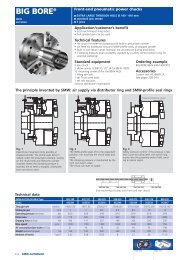
1. Description of function<br />
1.1 General function<br />
Self-contained frontend power chucks type <strong>BIG</strong> <strong>BORE</strong> are<br />
wedge hook chucks with large through hole with an integrated<br />
pneumatic actuating cylinder. The main use is clamping of<br />
tubes.<br />
The clamping/unclamping is done at stopped spindle by<br />
filling/exhausting the cylinder chambers with compressed air.<br />
The air must be cleaned and lubricated with a suitable<br />
air service unit with a filter, dryer and oiler. Actuation is<br />
done by an air distribution system which is mounted stationary<br />
on the headstock of the machine. When the correct clamping<br />
pressure in the cylinder chamber is reached the mounted<br />
safety control unit stops the airflow and disconnects the air<br />
distributor from the chuck. The clamping pressure is trapped in<br />
the cylinder chamber by a non-return valve.<br />
1.2 Air distribution system (pic. 1)<br />
The air for actuation is transmitted through the air distributor<br />
ring and the mounted profile seals to the chuck at stopped<br />
spindle only. The profile seals are designed so that the outside<br />
surface is bigger than the inside surface. When the profile seal<br />
is pressurized the bigger outside surface causes a radial deformation<br />
of the profile seals inwards until they are in full contact<br />
with the outside diameter of the chuck body. Now the profile<br />
seals seal all around the outside dia. of the chuck body and the<br />
air flows through the small holes of the profile seals into the<br />
corresponding chuck chamber.<br />
10 <strong>SMW</strong>-AUTOBLOK<br />
pic. 1<br />
When the airflow is stopped the elasticly free loaded profile<br />
seals lift completely off the chuck body and thus cannot wear<br />
out during rotation of the chuck. The air of the non-pressurized<br />
chamber exhausts mainly directly through the gap between<br />
the air distributor ring/profile seal and the chuck body.<br />
DESCRIPTION OF FUNCTION<br />
1.3 Safety non-return valve (pic. 2)<br />
The safety non-return valve is a brass valve body including 2<br />
steel sealing pistons. It is easily accessible through a plug on<br />
the face of the chuck. It guides the airflow from the profile<br />
seals through the channels to the corresponding chuck chamber.<br />
By pressurizing the different profile seals the clamping<br />
pressure is guided to the corresponding clamping chamber<br />
and in the same movement the other chamber can exhausts<br />
the air through the other side of the safety valve. As the safety<br />
valve acts like a shuttle valve any actuation causes a movement<br />
of the entire assembly in the ball of the chuck body. This<br />
allows to have the function for pressurizing the clamping<br />
chamber and exhausting the other chamber in one motion<br />
(see also page 11, pic. 2).
1.4 Jaw drive<br />
brass valve body<br />
steel sealing piston in<br />
“exhaust” position<br />
to cylinder chamber I<br />
The self-centering jaw drive on all 3 master jaws is ensured by<br />
a piston with a wedge hook machined into the piston collar.<br />
The force transmission is done by the 10° wedge hook from<br />
the piston to the master jaws.<br />
piston with wedge hook<br />
from cylinder chamber II<br />
from distributor ring to distributor ring<br />
steel sealing piston<br />
in “seal position”<br />
DESCRIPTION OF FUNCTION<br />
pic. 2<br />
The clamping forces are taken by the piston collar and are radially<br />
supported in the piston guide of the chuck body. The<br />
pneumatic actuation is done on to the piston cover that is bolted<br />
on to the piston in the pneumatic part of the chuck.<br />
pressurized chamber<br />
for o.d. clamping<br />
pressurized chamber<br />
for unclamping<br />
plug<br />
axial force<br />
force transmission<br />
piston guide<br />
on guide bush<br />
clamping force<br />
self-centering jaw drive of selfcontained<br />
frontend power chuck<br />
pic. 3<br />
master jaw<br />
piston collar<br />
piston guide<br />
piston cover<br />
<strong>SMW</strong>-AUTOBLOK 11
2. INSTALLATION<br />
prox. switch M12x1<br />
(Illustration without pressure control and<br />
without rapid stroke control)<br />
back plate<br />
bracket<br />
<strong>SMW</strong> profile seal<br />
12 <strong>SMW</strong>-AUTOBLOK<br />
DRMB<br />
distributor ring<br />
labyrinth gap 1,5 mm<br />
seal disc<br />
grease nipple<br />
air connection<br />
bolt<br />
T-nut<br />
master jaw<br />
piston cover<br />
guide bush<br />
piston<br />
cap<br />
chuck body<br />
pic. 4<br />
distributor ring<br />
labyrinth gap<br />
pic. 5<br />
safety non-return valve<br />
2.1 Distributor ring (see pic. 4)<br />
INSTALLATION<br />
The distributor ring must be mounted stationary onto the headstock of<br />
the spindle without any contact to the chuck. The distributor ring is<br />
a separate stationary part which is mounted with the distributor ring<br />
mounting bracket (DRMB) to the headstock of the machine and has to<br />
be held rigidly in axial and radial position. It can be centred and mounted<br />
on the cover of the front spindle bearing. Always reconfirm with<br />
the machine manufacturer for the best place for mounting the DRMB.<br />
The DRMB must have a large hole on the bottom in order to<br />
ATTENTION! allow coolant and exhaust air to escape!<br />
The brackets for the proximity switches for the pressure control and<br />
for the rapid stroke control can also be mounted onto the DRMB.<br />
2.2 Mounting to the machine spindle<br />
2.2.1 Mount chuck adapter plate with mounting bolts onto the<br />
machine spindle, and finish machine if necessary. Always apply correct<br />
torque to the machine mounting bolts.<br />
2.2.2 Bolt DRMB and distributor ring together, and mount onto<br />
the machine (see pic. 4).<br />
2.2.3 Lift the chuck with suitable lifting equipment (eyebolt) and<br />
mount carefully onto the machine. Be sure not to damage the distributor<br />
ring and the profile seals.<br />
2.2.4 Insert chuck mounting bolts, mount the chuck to the chuck<br />
adapter plate and check concentricity.<br />
2.2.5 Adjust labyrinth gap (1,5 mm = 0,059”) with thickness gage,<br />
and adjust concentricity of the distributor ring with dial indicator.<br />
2.2.6 Tighten all bolts with correct torque.<br />
2.2.7 Connect hoses for clamp and unclamp and check function<br />
and sealness.<br />
2.2.8 Insert gripmeter into the chuck and check grip force.<br />
Leave the grip force meter clamped for at least 1 hour<br />
WARNING!<br />
to ensure the chuck holds the grip force properly.<br />
2.3 Adjustment of proximity switch for pressure<br />
control<br />
2.3.1 Set the air control unit ACU-NT to adjustment mode (see<br />
<strong>manual</strong> ACU-NT page 14, 6.6).<br />
2.3.2 Orientate chuck so that the switch ring of the pressure control<br />
is underneath the slot where the proximity switch for the pressure<br />
control is mounted. Mount the proximity switch to the bracket and<br />
radially adjust to approx. 1 mm (0,039”) distance to the switch ring.<br />
2.3.3 Adjust the pressure control of the chuck to the requested<br />
min. pressure (see page 13, 3.3 and pic. 6, 7, 8, 9).<br />
2.3.4 Adjust axial position of the proximity switch, so that the<br />
proximity switch is actuated at low pressure or at position chuck<br />
open. At correct clamping there must be no alarm signal.<br />
2.4 Adjustment of proximity switch for rapid stroke<br />
control<br />
2.4.1 Set the air control unit ACU-NT to set-up mode for jaw<br />
movement (see <strong>manual</strong> ACU-NT page 14, 6.5).<br />
2.4.2 Orientate the chuck so that the switch ring for rapid stroke<br />
control is underneath the slot where the proximity switch for the<br />
rapid stroke control is mounted. Mount the proximity switch to the<br />
bracket and radially adjust to approx. 1 mm (0,039”) distance to the<br />
switch ring.<br />
2.4.3 Move the chuck master jaws to the position where the stroke<br />
changes from rapid stroke to clamping stroke.<br />
2.4.4 Adjust the axial position of the proximity switch so that at<br />
rapid stroke the proximity switch is actuated. At clamping stroke there<br />
must be no alarm signal.
3. Operation<br />
3.1 Operation<br />
3.1.1 Ensure that the self-contained frontend power chuck<br />
type Big Bore is well lubricated. If necessary relubricate on all grease<br />
nipples using original <strong>SMW</strong>-AUTOBLOK grease K05. Lubrication<br />
is done with closed jaws (all 3 jaws are in inward end position). A<br />
chuck that is not sufficiently lubricated does not offer full<br />
gripping force and causeS hazards!<br />
3.1.2 On the face of the chuck there is a plug with a 6 mm i.d.<br />
hex. Behind this plug the safety non return valve is mounted. It is<br />
important that the ball for the safety valve is slightly oiled so that<br />
the valve body can easily slight in the valve ball.<br />
Too much grease, dirt or chips in the ball of the safety valve<br />
can lock the safety valve or cause damage of the o-rings!<br />
WARNING!<br />
The air must be cleaned and lubricated with a suitable air<br />
service unit. Moisture or dirt can cause rust or contamina-<br />
WARNING! tion which can damage the seals of the chuck and thus<br />
can cause loss of clamping force.<br />
ATTENTION!<br />
Danger of loss of gripping force!<br />
Pressure control<br />
Monitoring of the clamping pressure on chuck o.d. clamping is possible<br />
with suitable safety control units only! (please refer to power<br />
safety control unit ACU-NT).<br />
3.2 Standard conditions<br />
The self-contained frontend power chucks type Big Bore are equipped<br />
with a pressure control for chuck o.d. clamping as a standard.<br />
This control contains the part 1, 2, 3 and 4 (see illustration below)<br />
and works as follows:<br />
The air pressure in chamber (S) creates a force on piston (4) that is<br />
equal or bigger than the counterforce created by the spring (1). This<br />
causes the switch ring (2) to move forward in working position (A).<br />
In this position the switch ring (2) can lock the proximity switch (3).<br />
standard setting<br />
Switch ring in position ok<br />
(for o.d. clamping only)<br />
Switch ring in alarm position<br />
low pressure in chuck chamber or jaws<br />
flush with chuck<br />
body<br />
pic. 6<br />
standard setting<br />
for 3 bar (43 psi)<br />
pic. 7<br />
OPERATION<br />
As the clamping pressure is correct no alarm signal is created and<br />
the machine spindle and the machining process can be started. In<br />
case the pressure in the clamping chamber for o.d. clamping drops<br />
below the preselected value correspondingly the pressure in chamber<br />
(S) is reduced. The lower pressure in chamber (S) causes a lower<br />
force against the tension of the spring (1). The spring causes the<br />
switch rod and thus the switch ring (2) to move backwards and thus<br />
creating an alarm signal by switching on the proximity switch (3).<br />
The signal of the proximity switch is detected by the built-in electronics<br />
of the ACU-NT and creates an alarm output signal which<br />
can be used to stop the machine spindle.<br />
3.3 Changing of the preset minimum pressure<br />
When the chuck is delivered from the factory a pressure control for<br />
o.d. clamping is set to a pressure of 3 bar (43 psi). In order to readjust<br />
this pressure following procedure is necessary:<br />
1. The chuck is clamped for o.d. clamping with a pressure that<br />
lateron is used as a clamping pressure to hold the part.<br />
2. Open counter nut (6) by 8 mm hex key.<br />
3. Readjust set screw (5) by 6 mm hex key until the pneumatic<br />
pressure in chamber (S) forces the switch ring to position A 11<br />
mm towards the backface of the chuck (see pic. 6).<br />
4. Tighten counternut (6) again.<br />
5. Open the chuck and reclamp for o.d. clamping with a pressure<br />
2 bar (29 psi) less then the initial pressure. Now switch ring (2)<br />
must reach the position 7 mm as shown in picture 7 as a maximum.<br />
In this position the switch ring creates an alarm signal as<br />
soon as the spindle starts rotating and the switch ring passes by<br />
the proximity switch. The built-in electronics in the ACU-NT<br />
detect the low pressure and create an alarm output signal. This<br />
can be used to stop the machine spindle. To check the function<br />
without rotating the spindle (rotating spindle by hand) the<br />
ACU-NT must be set to set-up mode (please refer to service and<br />
maintenance instruction of ACU-NT).<br />
Switch ring in alarm position<br />
low pressure in chuck chamber or jaws<br />
Switch ring in alarm position<br />
low pressure in chuck chamber or jaws<br />
pic. 8<br />
min. pressure set<br />
to 2 bar (29 psi)<br />
pic. 9<br />
min. pressure set<br />
to 4,5 bar 65 psi)<br />
assembly of pressure control<br />
<strong>SMW</strong>-AUTOBLOK 13
4. Maintenance<br />
4.1.1 Cleaning and lubrication of the chuck<br />
Constant clamping force, accuracy and service life of the chuck<br />
mainly depend on that the chuck is regularly cleaned and<br />
maintained. Rust, dust, chips and coolant increase the friction<br />
and thus increase wear of the chuck. Regular lubrication with<br />
<strong>SMW</strong>-AUTOBLOK K05 ensure high gripping force, accuracy<br />
and service life.<br />
4.1.2 Every 20-30 working hours the 3 grease nipples on<br />
the master jaws have to be lubricated with <strong>SMW</strong>-AUTOBLOK<br />
grease K05. After lubricating the chuck should be opened and<br />
closed 3 times without a clamped workpiece to spread the<br />
grease equally on all surfaces.<br />
4.1.3 Depending on the working conditions the<br />
safety valve has to be removed, cleaned and oiled<br />
minimum once per week. Also the ball of the<br />
WARNING! safety valve has to be cleaned and checked for<br />
damage.<br />
4.1.4 The serration of the master jaws and the top jaws<br />
must be cleaned when changing all repositioning jaws.<br />
4.1.5 Contamination of rust, dust, fine chips or coolant<br />
cannot be avoided, even if all gaps are sealed by very close<br />
tolerances. Therefore the chuck has to be disassembled and<br />
completely cleaned and relubricated max. every 6 months. In<br />
case of big amounts of dust or coolant contaminating the<br />
chuck this interval has to be shortened accordingly.<br />
4.2 Top jaws<br />
4.2.1 The fine serration of the master jaws and the top<br />
jaws on the Big Bore chucks is 3/32” x 90°. The increments<br />
from teeth to teeth are approx. 2.4 mm (approx. 3/32”).<br />
Please observe that the top jaws to clamp the components<br />
are positioned on the master jaws so that max. 2/3<br />
of the total jaw stroke are used to clamp the part (1/3<br />
remaining as remaining jaw stroke). Hard top jaws must<br />
only be used in sets (marked with 1, 2, 3). Please observe correct<br />
position of the top jaws 1, 2, 3 on the corresponding<br />
master jaws, to reach best concentricity.<br />
4.2.2 Machining of soft top jaws on the self-contained<br />
frontend power chuck type Big Bore must be done<br />
in the same clamping position using the same clamping<br />
pressure that will be used for the machining process<br />
afterwards. Please note that all mounting bolts must be<br />
tightened with a correct torque.<br />
4.2.3 When mounting hard or soft top jaws<br />
always use a torque wrench. Always tighten the<br />
mounting bolts with correct torque. Always use<br />
WARNING!<br />
mounting bolts with minimum quality class 10.9!<br />
14 <strong>SMW</strong>-AUTOBLOK<br />
MAINTENANCE / JAWS DISASSEMBLING<br />
5.1 Disassembling (for reference numbers please<br />
refer to page 15)<br />
5.1.1 Disconnect both fittings from distributor ring (4).<br />
Loose mounting bolts of distributor ring mounting bracket<br />
mounted to the machine headstock. Use eyebolt M12 or M16<br />
in radial eyebolt holes and engage suitable lifting equipment<br />
into crane. Loosen mounting bolts that hold the chuck on the<br />
adapter plate. Now take off the complete chuck assembly with<br />
a crane and place safely on a work bench. Please obersve<br />
hands and feet because chuck is very heavy.<br />
5.1.2 Disassemble profile seals (5 and 8) from distributor<br />
ring (4) and check for wear. If necessary replace by new original<br />
<strong>SMW</strong>-AUTOBLOK profile seals. If the profile seals are not<br />
worn out clean and grease slightly. When reassembling the<br />
profile seals to the air dsitributor ring ensure that the small<br />
holes in the profile seals are as far as possible away from the<br />
pneumatic fittings of the distributor ring.<br />
5.1.3 Take out safety non-return valve (10) by opening plug<br />
(9) with o-ring (39) carefully.<br />
Attention: The chuck is still pressurized!<br />
Please use clothrag to cover and protect yourself<br />
during disassembling the safety nonreturn<br />
valve.<br />
WARNING! It is absolutely necessary to take off the<br />
safety non-return valve before continuing<br />
any other disassembling!<br />
Check all parts and o-rings of the valve system for<br />
wear or damage, and replace if necessary!<br />
5.1.4 When the safety valve is disassembled from the<br />
chuck the backplate (12) with the o-rings (34, 35) can be disassembled<br />
by loosening the head socket screws (11). Before<br />
removing the backplate disassemble the switch rings for pressure<br />
control and stroke control.<br />
5.1.5 Open head socket screws (13) which hold the piston<br />
cover (14) onto the piston (21).<br />
5.1.6 Use 2 of the screws in the 2 tapped holes in the<br />
piston cover (14) to lift the piston cover (14) off the piston (21).<br />
5.1.7 Open the head socket screws (15) of the guide bush<br />
(16) and disassemble the guide bush (16) by pushing towards<br />
the front.<br />
5.1.8 Open head socket screws (17 or 17.1) and remove<br />
sealing disc (19 or 19.1) and take out the o-ring (20 or 20.1).<br />
Attention: On older chucks there can be washers underneath<br />
the heads of the bolts. Please do not loose them!<br />
5.1.9 The piston (21) can now be removed from the chuck<br />
body (23). Also the master jaws (22) can be slided out radially<br />
towards the center of the chuck. The jaws as well as the piston<br />
are marked with 1,2,3. When reassembling please observe correct<br />
position in chuck body.<br />
5.1.10 Clean all parts of the chuck with suitable cleaning<br />
liquid and dry. Always observe all safety regulations. Please<br />
check all parts for wear or damage and replace if necessary.<br />
We recommend to use a new seal kit and replace all o-rings<br />
before reassembling the chuck. All o-rings and parts in the<br />
pneumatic part must be oiled, all parts in the mechanical part<br />
(piston and master jaws) must be lubricated with <strong>SMW</strong>-AUTO-<br />
BLOK grease K05.<br />
Please note that the seal in the sealing disc (part 32) in the<br />
chuck is a Teflon seal. Normally this seal does not have to be<br />
changed. In case it is damaged, a o-ring in the seal kit replaces<br />
the Teflon seal and its o-ring!
5.2 Reassembling<br />
5.2.1 Lubricate master jaws and piston with <strong>SMW</strong>-AUTO-<br />
BLOK grease K05. Insert master jaws (22) into the corresponding<br />
guideways of the chuck body (23). Mount the o-ring (33)<br />
into the piston (21). Slide in the piston with a wedge hook into<br />
the wedge hook of the master jaws (22) up to the frontend<br />
position. Please observe marking 1, 2, 3 on chuck body (23),<br />
piston (21) and master jaws (22).<br />
5.2.2 Reinsert o-ring (20 or 20.1) into sealing disc (19 or<br />
19.1), and mount together with O-ring (32) into the chuck<br />
body. Use head socket screws (17) to bolt in the sealing disc<br />
(19 or 19.1) into the chuck body (23). On older version chucks<br />
do not forget the washers underneath the heads of the screw!<br />
5.2.3 Slide in guide bush (16) from the frontside into the<br />
chuck and screw-in 3 screws (15).<br />
5.2.4 Insert piston cover (14) with the o-rings (31, 36) and<br />
mount with head socket screws (13) to the piston (21).<br />
5.2.5 Put backplate (12) the o-ring (34, 35) back onto the<br />
chuck body and tighten head socket screws (11) in chuck body<br />
(23). Reassemble the switch rings for pressure control and stroke<br />
control.<br />
5.2.6 Lubricate the safety valve (10) and the safety valve<br />
ball in the chuck body (23) slightly with oil and slide in the<br />
valve into the body. Please observe that the valve must slide<br />
easily in the ball. Now reinsert o-ring (39) and close plug (9).<br />
All parts of the <strong>SMW</strong>-AUTOBLOK self-contained<br />
frontend power chuck move easily. When reassembling<br />
the chuck never apply force!<br />
ATTENTION!<br />
5.3 Trouble shooting<br />
5.4 Spare parts<br />
REASSEMBLING<br />
Trouble: caused by and action:<br />
5.3.1 On o.d. or i.d. clamping:<br />
The chuck is clamping but<br />
reverses the movement immediately.<br />
5.3.2 Air leakage inside the<br />
air distributor ring during<br />
actuation of the jaws.<br />
5.3.3 The chuck is loosing<br />
clamping force.<br />
5.3.4 Air leakage on the<br />
chuck after finishing the clamping<br />
cylce.<br />
The safety valve does not move<br />
in the bore. Remove safety<br />
valve (10), clean and oil slightly.<br />
Reassemble the safety valve<br />
and check for easy movement.<br />
Contamination underneath<br />
the profile seals (5/8): Remove<br />
air distributor ring (4), profile<br />
seals (5/8), check for damage<br />
and clean and oil slightly. If<br />
necessary replace!<br />
Disassemble the chuck completely,<br />
check all parts for<br />
damage, clean, replace all orings<br />
and safety valve.<br />
O-rings or seals in the safety<br />
valve damaged or worn out.<br />
See also point 5.3.3.<br />
Below drawing shows the most common spare parts for the<br />
chuck. Please always state chuck type, size and serial number<br />
when ordering spare parts. Seal kits are available in sets only!<br />
(Pressure control and<br />
stroke control are not<br />
shown)<br />
<strong>SMW</strong>-AUTOBLOK 15
General safety instructions<br />
1.1 Correct use<br />
<strong>SMW</strong>-AUTOBLOK control units work safely and<br />
troublefree if they are used according to their spe-<br />
WARNING! cification i.e. to actuate and control selfcontained<br />
air chucks on turning machines.<br />
Any other use can cause hazards.<br />
Important: The control units AC-SP/AC-BB do not allow to<br />
use the safety features pressure control of clamped chuck in<br />
o.d. clamping and the rapid stroke control. All necessary steps<br />
to ensure safety must be taken.<br />
WARNING!<br />
Description of function AC-SP / AC-BB<br />
The AC-SP / AC-BB are designed and manufactured to operate<br />
pneumatic front and chucks of the <strong>SMW</strong>-AUTOBLOK series<br />
SP and <strong>BIG</strong> <strong>BORE</strong>.<br />
The main part is a pneumatic block with pressure regula-tion,<br />
pressure switch, two 3/2 valves with quick exhaust and 2 air<br />
flow sensors.<br />
The 2 current monitors and the 2 relays are intended to be<br />
installed in the machine side control unit. They can be plugged<br />
on usual 35 mm mounting brackets.<br />
The control unit has no own operating devices. The pneumatic<br />
block that contents all pneumatic parts should be mounted<br />
in a well accessible place at the machine.<br />
The installation of a <strong>manual</strong> switch or foot switch or the connection<br />
for automatic operation (machine control) is required.<br />
16 <strong>SMW</strong>-AUTOBLOK<br />
1.2 Personnel<br />
Control units must be installed, operated and<br />
maintained only by qualified and regularly trained<br />
personnel.<br />
1.3 Protections<br />
During actuating of the chuck the flow of the air<br />
to the chuck is monitored via airflow sensors (air<br />
WARNING!<br />
flow/pressure). As soon as the actuation cycle of<br />
the chuck is finished and the air flow stops the pressure in the<br />
supply lines is switched off. The built-in non-return valve in the<br />
chuck body closes and traps the air pressure inside of the<br />
chuck body during the chuck rotates.<br />
pressure switch<br />
(optional pressure converter)<br />
pressure regulation<br />
with pressure gauge<br />
for clamping pressure<br />
3/2 valves<br />
air flow sensor<br />
CONTROL UNIT AC-SP / AC-BB<br />
During machining the power chuck and the clamped<br />
component must be protected by safety guard. Open<br />
machine door only when machine spindle is completely<br />
stopped. Maintenance and actuation of the power chuck<br />
must only be carried out when machine spindle is stopped.<br />
1.4 Remaining risks<br />
The type of components (shape, weight, unbalan-<br />
WARNING! ce, material etc.) has a big influence on the system<br />
“machine tool - power chuck - component”. For<br />
that reason there is always a residual risk.<br />
These residual risks must be calculated by the user and have to<br />
be eliminated by suitable actions.<br />
1.5 Maintenance<br />
The function of the control unit has to be checked<br />
once a month due to safety reasons. The level of<br />
WARNING!<br />
the oil in the air service unit (optional) has to be<br />
checked regularly. The function of the air service unit (optional)<br />
has to be checked regularly. A air service unit to clean and lubricate<br />
the air is mandatory!<br />
For any problems or questions please contact <strong>SMW</strong>-<br />
AUTOBLOK directly or one of our authorized offices.<br />
current monitor<br />
relay<br />
Function sequence<br />
Filtered, dehydrated and lubricated air connected at the pressure<br />
regulation.<br />
When switching the solenoid valves clamping/unclamping the<br />
air flow in the corresponding line to the chuck will be released.<br />
The in-built air flow sensors together with the current monitors<br />
register the air flow and keep it up (red LED is on).<br />
(Attention: Impulse must be current for 1 second to make the<br />
unit come to self-holding through the air flow sensors.)<br />
After reaching of the clamping position with a pre-adjusted<br />
pressure the airflow stops. The air flow sensors register this<br />
and give the sign “release” through the current monitors (red<br />
LED goes off). The machining process can be started.
The release of the machine spindle (only possible at full<br />
spindle stop) only happens when conditions A + B are given:<br />
Condition A<br />
Air pressure (clamping pressure) in the chuck reaches during<br />
the filling process (clamping) the pre-adjusted value at the<br />
pressure switch.<br />
Optional accessories:<br />
Foot switch F2 incl. 4 m wire<br />
Id.-No. 013324<br />
Standard delivery range:<br />
like shown without hoses and<br />
connectors<br />
Air service unit<br />
(must be used to clean and<br />
lubricate the air!)<br />
chuck connections<br />
clamping/unclamping<br />
CONTROL UNIT AC-SP / AC-BB<br />
Condition B<br />
Clamping process is completed, that means in the line for<br />
clamping there is no more air flow.<br />
Attention: At running spindle the operation of the<br />
chuck is not possible.<br />
fixing holes<br />
total depth 110 mm<br />
connection line<br />
pressure<br />
Type I.D. Id.-No.<br />
AC-SP 24 V 1/4” 192432<br />
AC-SP 110 V 1/4” 192446<br />
AC-SP 220 V 1/4” 192447<br />
AC-BB 24 V 1/2” 192433<br />
AC-BB 110 V 1/2” 192448<br />
AC-BB 220 V 1/2” 192449<br />
<strong>SMW</strong>-AUTOBLOK 17
Installation<br />
Fixing the control unit<br />
The control unit has to be mounted well accessible in a<br />
dry area, e.g. close to the control panel of the machine<br />
Electrical connection<br />
Electric parts (current monitors and relays) are to be<br />
mounted in the machine side control cabinet or at<br />
another suitable place. Please consider general regulations<br />
(see wiring diagram page 6).<br />
Electric power supply<br />
The power supply is either 24 VDC, 110 VAC or 230<br />
VAC, 50/60 Hz. The AC-SP/AC-BB are not equipped<br />
with a ON/OFF switch and are connected at the control<br />
cabinet of the machine.<br />
Pneumatic power supply<br />
(See pneumatic plan page 6.). The pneumatic line has<br />
to be connected with the pressure regulating valve.<br />
Connect control unit and chuck with hoses. Hoses with<br />
low elasticity, I.D. min. for AC-SP = 8 mm, for AC-BB =<br />
12 mm, are to be used!<br />
WARNING!<br />
18 <strong>SMW</strong>-AUTOBLOK<br />
The hoses, fittings, aramtures and tubes<br />
must ot be smaller in ID than 8 mm<br />
(AC-SP) or12 mm (AC-BB)<br />
min. operating pressure = 2 bar<br />
max. operating pressure = 10 bar<br />
All connections need to be checked for leakage.<br />
Recommended oil for air lubrication (air maintenance<br />
unit optional) HLP 32.<br />
WARNING!<br />
Air service unit to clean and lubricate the<br />
air must be installed! Rust or contamination<br />
can cause damage of seals and thus<br />
loss of clamping force.<br />
Putting into operating<br />
Switch on electric power supply<br />
Green LED at the current monitors is on and indicates<br />
ready for operation.<br />
Adjust pressure regulator to min. pressure 2 bar.<br />
Switch operating device (foot switch, <strong>manual</strong> switch<br />
or M-function).<br />
During the operation/movement of the chuck, additionally<br />
the red LED on the corresponding monitor is<br />
on and by this indicates the air flow. After reaching of<br />
the end-position the air flow stops and the red LED<br />
goes off. Repeat this sequence for both operating<br />
directions (clamping/unclamping) at min. and max.<br />
operating pressure.<br />
The sensibility of the air flow sensor is adjusted to a<br />
standard value from the manufacturer. It can be readjusted<br />
according to the local conditions at the<br />
potentiometer “sensibility/Empfindlichkeit”.<br />
Operating<br />
6. Maintenance<br />
CONTROL UNIT AC-SP / AC-BB<br />
Make sure that the adjustment of the air<br />
flow sensor insures a correct clamping<br />
force at the chuck. (Check clamping<br />
WARNING!<br />
force with a suitable grip force meter, see<br />
operating <strong>manual</strong> of the chuck). Unsuitable clamping<br />
force can cause accidents at the machine.<br />
Adjust lubricator at the maintenance unit (optional).<br />
oil amount approx. 1 drop for 2 - 3 clamping cycles.<br />
Switch on unit together with the machine<br />
The unit is ready for operation, when the both green<br />
LED’s on the current monitors are on.<br />
Adjust required clamping pressure and pressure switch<br />
accordingly.<br />
Release clamping/unclamping by connected operating<br />
device.<br />
To get the unit in self-holding position by the air flow<br />
sensors, the impulse must be current by approx. 1<br />
second.<br />
Every 3 days Check oil volume (maintenance unit<br />
optional)<br />
Refill oil type HLP 32.<br />
Weekly Check function and adjustment of the<br />
lubricator (optional)<br />
Adjustment: one drop per 2 - 3 clamping<br />
cycles.<br />
Monthly Check the function of the control unit.<br />
Monthly Check the clamping force of the chuck<br />
therefore clamp grip force meter in the<br />
chuck. The cripping force must not<br />
decrease by more than 10 % in one hour<br />
(see operating instructions of the chuck).<br />
Trouble shooting<br />
Green LED at the current monitors is not on<br />
⇒ no electric power supply<br />
Red LED at the current monitors does not go off<br />
a) ⇒ air flow still existing because of leaking hoses<br />
connectors, or chuck<br />
b) ⇒ sensibility of air flow sensors is adjusted wrongly<br />
Pneumatic control switches off without movement of<br />
the chuck<br />
a) ⇒ pressure too low<br />
b) ⇒ chuck or safety valve blocked mechanically<br />
c) ⇒ time of impulse for clamping/unclamping too<br />
short
PNEUMATIC DIAGRAM AC-SP / AC-BB<br />
pneumatic power supply<br />
max. pressure 10 bar<br />
WIRING DIAGRAM AC-SP / AC-BB<br />
relais<br />
pressure reducer<br />
hoses, fittings, aramtures and<br />
tubes must not be smaller in<br />
ID than<br />
8 mm (AC-SP) or<br />
12 mm (AC-BB)<br />
period of impulse for clamping/unclamping 1 s<br />
air flow<br />
sensor<br />
air flow<br />
sensing<br />
valve<br />
Y1<br />
voltage only at spindle stop<br />
pressure control<br />
(option)<br />
clamping chuck<br />
CONTROL UNIT AC-SP / AC-BB<br />
air flow<br />
sensing<br />
valve<br />
Y2<br />
operating voltage ok<br />
GREEN RED<br />
air flow current<br />
sensibility<br />
pressure converter<br />
0-10 bar<br />
air flow<br />
sensor<br />
option<br />
<strong>SMW</strong>-AUTOBLOK 19
Universal, electronic micro-processor compact control unit<br />
for Big Bore chucks in 1/2” design type ACU-NT<br />
All safety systems integrated<br />
Easy installation - no other devices needed<br />
Can be connected to all common voltages<br />
LCD display in English/German<br />
Quick chuck actuation by 1/2” pneumatic parts<br />
Line pressure<br />
LCD display<br />
English/German<br />
Key switch to select<br />
<strong>manual</strong> operation,<br />
foot pedal or<br />
automatic cycle<br />
Accessories:<br />
Foot pedal F2<br />
with 4 m cable<br />
Id.No. 013324<br />
Options:<br />
Line pressure control 192437<br />
Pressure control for<br />
chuck o.d. clamping<br />
Rapid stroke control<br />
(for BB-N ES only)<br />
20 <strong>SMW</strong>-AUTOBLOK<br />
192435<br />
192436<br />
Interface 192439<br />
Lubrication unit 192438<br />
Second independent ok<br />
relay<br />
192440<br />
CONTROL UNIT ACU-NT<br />
Push button<br />
close (B) / open (A)<br />
Reset Hysteresis for<br />
pressure switch<br />
Electric connections<br />
Proximity switch for pressure<br />
and rapid stroke control signals<br />
Id.No. 090636<br />
Air service unit 1/2”<br />
Id.No. 192074<br />
I.d. / o.d. clamping<br />
Protection cover<br />
A<br />
B<br />
1/2” pressure<br />
connecting lines<br />
to the chuck<br />
clamp/unclamp<br />
Standard equipment:<br />
(as shown, without cable, without hoses<br />
without fittings)<br />
Pressure is shown in the display, minimum pressure pre-selectable,<br />
contact for monitoring the pressure.<br />
Pressure control of the chuck chamber via proximity switch, contact for monitoring,<br />
self diagnostic of proximity switch (for o.d. clamping only).<br />
Control of rapid/clamping stroke via proximity switch, contact for monitoring,<br />
self diagnostic of proximity switch.<br />
To show data chuck clamped, unclamped, too long clamping cycle, air supply lines<br />
leaking, i.d./o.d. clamping, pressure control deactivated on the machine display.<br />
Actuation of an external lubrication unit with intervals, oil reservoir control,<br />
pressure control.<br />
Additional relay to double confirm for spindle run.
Pneumatic diagram ACU-NT<br />
Electric diagram ACU-NT<br />
CONTROL UNIT ACU-NT<br />
<strong>SMW</strong>-AUTOBLOK 21
Electric connection ACU-NT<br />
For further information please refer to the service <strong>manual</strong> ACU-NT<br />
22 <strong>SMW</strong>-AUTOBLOK<br />
CONTROL UNIT ACU-NT