SP®+ SP-ES + SP-L - SMW Autoblok
SP®+ SP-ES + SP-L - SMW Autoblok
SP®+ SP-ES + SP-L - SMW Autoblok

Create successful ePaper yourself
Turn your PDF publications into a flip-book with our unique Google optimized e-Paper software.
<strong>SP</strong> ® + <strong>SP</strong>-<strong>ES</strong> + <strong>SP</strong>-L<br />
INCH<br />
serration<br />
The principle invented by <strong>SMW</strong>:<br />
air supply via distributor ring and<br />
<strong>SMW</strong>-profile seal rings<br />
Fig. 1<br />
Open/close movement (only possible<br />
at stopped spindle). The profile<br />
seals deform radially under the<br />
pneumatic pressure, sealing on the<br />
chuck body and filling the cylinder<br />
chamber. When the clamping<br />
pressure is reached, the air feed is<br />
stopped, closing the twin nonreturn<br />
valve.<br />
Technical data<br />
218 <strong>SMW</strong>-AUTOBLOK<br />
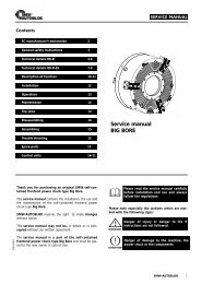
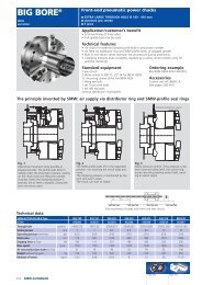
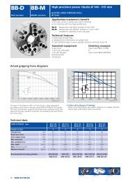
Front-end pneumatic power chucks<br />
n EXTRA LARGE THROUGH HOLE Ø 26 - 115 mm<br />
n 3 jaws<br />
n <strong>SP</strong>-<strong>ES</strong>: chuck with rapid and clamping stroke<br />
n <strong>SP</strong>-L: chuck with long jaw stroke<br />
Application/customer’s benefit<br />
• Universally used in turning machines, rotary tables, handling equipment, welding etc.<br />
• For machines without hydraulic cylinder<br />
• Easy exchange for manual chucks<br />
Technical features<br />
• Power chuck with built-in pneumatic cylinder. Force transmission via wedge hook<br />
• Mounting of the distributor ring on the headstock or with the centering ring on the<br />
chuck with anti-rotation bracket<br />
• Open and close only at stopped spindle. Air transmission via distributor ring and<br />
<strong>SMW</strong>-profile seals (monitoring by <strong>SMW</strong> control cabinet)<br />
• Easy installation with no additional adapters required<br />
Standard equipment Ordering example<br />
3 jaw chuck 3 jaw chuck <strong>SP</strong> 160/Z155<br />
1 set T-nuts with bolts<br />
1 set soft top jaws<br />
2 elbow unions G1/4” (G1/8” on <strong>SP</strong> 125) Accessories<br />
Spacer ring and centering ring, without Control units<br />
distributor ring bracket/anti-rotation bracket (see pages 238-241)<br />
Fig. 2<br />
The <strong>SMW</strong>-profile seals lift to the<br />
expanded position, not touching<br />
the chuck body anymore.<br />
The clamping pressure is maintained<br />
by the twin non-return<br />
valve. The chuck can start to<br />
rotate.<br />
Two ways of mounting the distributor ring:<br />
n spacer ring and distributor ring bracket<br />
n centering ring and anti rotation bracket<br />
Distributor ring<br />
Spacer ring<br />
Fig. 3<br />
Distributor ring bracket fixed<br />
(stationary) on the headstock to<br />
support the distributor ring<br />
mounted with the spacer ring.<br />
No contact between the static<br />
distribution ring and the rotating<br />
chuck.<br />
Anti-rotation bracket<br />
Centering ring<br />
Fig. 4<br />
Distributor ring mounted on the<br />
outer diameter of the chuck with<br />
the centering ring (teflon part<br />
subject to wear).<br />
Need of an anti-rotation bracket<br />
fixed to the machine headstock.<br />
<strong>SP</strong> 125-26 <strong>SP</strong> 160-38 <strong>SP</strong> 240-78 <strong>SP</strong> 280-92 <strong>SP</strong> 350-115 <strong>SP</strong> 350-115 <strong>ES</strong> <strong>SP</strong>-L 350-90<br />
012044 012045 053170 052778 012588 052850 053193<br />
mm 3 4.2 4.2 5 5 (10) + 5* 24<br />
bar 2/10 2/10 2/10 2/10 2/10 2/10 2/10<br />
cm2 129 206 290 535 486 486 486<br />
kN 20 35 60 95 88 88 31<br />
4000 3500 2800 2200 2200 2200 1000<br />
4200 4200 3500 3200 3000 3000 1000<br />
l 1.4 3.4 5.2 10.0 9.4 13.5 13.5<br />
kg 11 23 40 62 78 91 97<br />
kg . m2 <strong>SMW</strong>-AUTOBLOK Type<br />
Id. No.<br />
Stroke per jaw<br />
Operating pressure min./max.<br />
Piston area max.<br />
Gripping force at 6 bar<br />
Max. speed (distribution ring with centering ring) r.p.m.<br />
Max. speed (distribution ring fixed stationary) r.p.m.<br />
Air consumption/jaw stroke at 6 bar<br />
Mass (without jaws)<br />
Moment of inertia<br />
0.028 0.125 0.412 0.823 1.125 1.62 1.62<br />
*10 mm extended stroke (must not be used for clamping) + 5 mm clamping stroke<br />
Page 221 Page 220
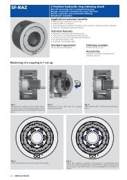
Front-end pneumatic power chucks<br />
n EXTRA LARGE THROUGH HOLE Ø 26 - 115 mm<br />
n 3 jaws<br />
n <strong>SP</strong>-<strong>ES</strong>: chuck with rapid and clamping stroke<br />
n <strong>SP</strong>-L: chuck with long jaw stroke<br />
Fsp Gripping force (total on 3 jaws) (kN)<br />
350-115<br />
240-78<br />
125-26<br />
160-38<br />
L 350-90<br />
280-92<br />
*All hoses must be<br />
min. Ø 9 mm i.d.<br />
Subject to technical changes<br />
For more detailed information please ask for customer drawing<br />
Speed (r.p.m.)<br />
*<br />
<strong>SP</strong> ® + <strong>SP</strong>-<strong>ES</strong> + <strong>SP</strong>-L<br />
INCH<br />
serration<br />
Actual gripping force diagram<br />
The data in the diagram refer to 3-jaw-chucks, newly maintained<br />
according to their service manuals, using <strong>SMW</strong>-AUTOBLOK K05 grease,<br />
operated at 6 bar.<br />
The speeds refer to a static bracket. The static and dynamic gripping<br />
forces have been measured using MHB hard top jaws placed in a position,<br />
not exceeding the outer diameter of the chuck.<br />
Safety advice/danger of damage:<br />
When using taller/heavier jaws and/or clamping on a bigger diameter<br />
reduce operation pressure/rotating speed accordingly.<br />
Jaw position: Open for external clamping<br />
<strong>SMW</strong>-AUTOBLOK Type<br />
<strong>SP</strong> 125-26 <strong>SP</strong> 160-38 <strong>SP</strong> 240-78 <strong>SP</strong> 280-92 <strong>SP</strong> 350-115 <strong>SP</strong> 350-115 <strong>ES</strong> <strong>SP</strong>-L 350-90<br />
Mounting<br />
Z120 Z155 Z195 Z235 Z235 Z235 Z235<br />
A mm 136 171 240 284 350 360 360<br />
B mm 26 38 78 92 115 115 90<br />
C mm 204 255 300 372 372 372/380 372/380<br />
D H6 mm 120 155 195 235 235 235 235<br />
E mm 160 205 248 315 315 315 315<br />
Fixing bolts circle (6 x 60°) F mm 137 180 223.8 290.5 290.5 290.5 290.5<br />
Stud screw with nut<br />
G mm M8 M12 M12 M12 M12 M12 M12<br />
G1 mm 30 40 40 39 39 39 39<br />
H mm 103 131 135.5 157.5 157.5 191.5 191.5<br />
H1 mm 101.5 129.5 134 156 156 190 190<br />
J mm 6.5 6.5 6.5 6.5 6.5 6.5 6.5<br />
Fixing bolts circle 6 x 60°/M6 K mm 190 242 285 358 358 358 358<br />
L mm 10 14.5 15 21 21 21 21<br />
M mm 35 46 48 58 62 92 92<br />
Pneumatic connection N inch G 1/8" G 1/4" G 1/4" G 1/4" G 1/4" G 1/4" G 1/4"<br />
O mm 19 26 26.5 33 33 33 33<br />
P mm 29 33 33 33 33 33 33<br />
R mm 43 52 52 60 60 60 60<br />
Anti-rotation pin<br />
S mm 8 12 12 12 12 12 12<br />
a mm 24 30 36 44 44 44 44<br />
b mm 12 14 17 21 21 21 21<br />
Serration c inch 1/16" x 90° 1/16" x 90° 1/16" x 90° 1/16" x 90° 1/16" x 90° 1/16" x 90° 1/16" x 90°<br />
Bolt DIN 912 12.9<br />
d mm M8 x 30 M10 x 35 M12 x 35 M16 x 35 M16 x 35 M16 x 35 M16 x 35<br />
min. e mm 6 8 9.5 12 12 12 12<br />
T-nuts distance min./max. f mm 17/25 21/31 22/41.5 25/51 25/72 25/72 25/72<br />
Serration length<br />
g mm 40 50 59 75 93 92 95<br />
min./max. h mm 25/28 34.9/39 57.7/61.9 70/65 79/84 85/100 85/109<br />
α° deg. 0° 0° 30° 0° 0° 0° 0°<br />
β° deg. 30° 30° 30° 45° 45° 45° 45°<br />
<strong>SMW</strong>-AUTOBLOK 219<br />
9
<strong>SP</strong> ® + <strong>SP</strong>-<strong>ES</strong> + <strong>SP</strong>-L<br />
INCH<br />
serration<br />
MHB-D<br />
Hard reversible<br />
top jaws<br />
AWB-D<br />
Soft top jaws<br />
NST T-nuts<br />
For further<br />
jaws and<br />
accessories<br />
please ask for<br />
our 150 pages<br />
special<br />
catalogue!<br />
220 <strong>SMW</strong>-AUTOBLOK<br />
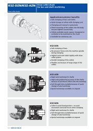
Chuck type<br />
n Top jaws<br />
n T-nuts<br />
<strong>SP</strong> 125-26 <strong>SP</strong> 160-38 <strong>SP</strong> 240-78 <strong>SP</strong> 280-92 <strong>SP</strong> 350-115 (+<strong>ES</strong>+L)<br />
Jaw type<br />
MHB-D 130 MHB-D 160 MHB-D 200 MHB-D 251 MHB-D 315<br />
Jaw Id. No. (set ) 12081306 12081636 12082036 12083036 12083186<br />
B 30 34 40 45 50<br />
H 34 39 45 56 56<br />
L 58 65 82 105 122<br />
T 8.5 10 10.5 13.5 13.5<br />
N 12 14 17 21 21<br />
Serration<br />
1/16" x 90° 1/16" x 90° 1/16" x 90° 1/16" x 90° 1/16" x 90°<br />
a 13 18 19 26 43<br />
b 16 16 23 30 30<br />
c 16 16 23 30 30<br />
kg/set<br />
0.6 0.9 1.7 2.85 4.05<br />
Chuck type<br />
<strong>SP</strong> 125-26 <strong>SP</strong> 160-38 <strong>SP</strong> 240-78 <strong>SP</strong> 280-92 <strong>SP</strong> 350-115 (+<strong>ES</strong>+L)<br />
Jaw type<br />
WBSA-D 125 AWB-D 165 AWB-D 200 AWB-D 250 AWB-D 315<br />
Jaw Id. No. (set) 12071300 035954 081616 081618 081619<br />
B 30 40 40 50 50<br />
H 30 40 40 50 50<br />
L 60 80 90 120 140<br />
N 12 14 17 21 21<br />
Serration<br />
1/16" x 90° 1/16" x 90° 1/16" x 90° 1/16" x 90° 1/16" x 90°<br />
a 29 43 53 70 90<br />
b 16 22 22 28 28<br />
kg/set<br />
0.9 2.0 2.7 5.1 6.3<br />
Chuck type<br />
<strong>SP</strong> 125-26 <strong>SP</strong> 160-38 <strong>SP</strong> 240-78 <strong>SP</strong> 280-92 <strong>SP</strong> 350-115 (+<strong>ES</strong>+L)<br />
T-nut type<br />
NST 12 NST 14 NST 17-4 NST 21-5 NST 21-5<br />
T-nut Id. No.<br />
089810 013863 013864 033429 033429<br />
N 12 14 17 21 21<br />
H 21.5 26.5 26.5 30 30<br />
h 7.5 9.5 9.5 11 11<br />
G M8 M10 M12 M16 M16<br />
Bolt<br />
DIN 912 12.9<br />
M8 x 30 M10 x 35 M12 x 35 M16 x 35 M16 x 35<br />
Tighten torque<br />
Md max. (Nm)<br />
30 50 70 150 150
n Adapters<br />
n Grease<br />
Adapters for <strong>SP</strong> chucks<br />
ISO-A<br />
DIN 55026<br />
mounting<br />
adapters<br />
DIN 55027<br />
bayonet<br />
mounting<br />
adapters<br />
type C<br />
DIN 55029<br />
camlock<br />
mounting<br />
adapters<br />
type S<br />
Chuck type<br />
Nose dim.<br />
Id. No.<br />
<strong>SP</strong> 125-26 <strong>SP</strong> 160-38 <strong>SP</strong> 240-78 <strong>SP</strong> 280-92 <strong>SP</strong> 350-115 (+ <strong>ES</strong> + L)<br />
A5 A5 A6 A5 A6 A8 A6 A8 A11 A6 A8 A11<br />
017083 017085 017086 017088 080174 017090 017092 017093 017094 017092 017093 017094<br />
A mm 26.0 25.5 25.5 25.5 32.2 34.0 32.2 38.2 36.0 32.2 38.2 36.0<br />
B mm 82.57 82.57 106.39 82.57 106.39 139.73 106.39 139.73 196.88 106.39 139.73 196.88<br />
C mm 104.8 104.8 133.4 104.8 133.4 171.4 133.4 171.4 235.0 133.4 171.4 235.0<br />
Chuck type <strong>SP</strong> 125-26 <strong>SP</strong> 160-38 <strong>SP</strong> 240-78 <strong>SP</strong> 280-92 <strong>SP</strong> 350-115 (+ <strong>ES</strong> + L)<br />
Nose dim. C5 C5 C6 C5 C6 C8 C6 C8 C11 C6 C8 C11<br />
Id. No. 017056 017058 017059 017061 017062 017063 017065 017066 017067 017065 017066 017067<br />
A mm 19.0 25.5 25 25.5 29.0 32.2 29.0 32.2 36.5 29.0 32.2 36.5<br />
B mm 82.57 82.57 106.39 82.57 106.39 139.3 106.39 139.73 196.88 106.39 139.73 196.88<br />
C mm 104.8 104.8 133.4 104.8 133.4 171.4 133.4 171.4 235.0 133.4 171.4 235.0<br />
Chuck type <strong>SP</strong> 125-26 <strong>SP</strong> 160-38 <strong>SP</strong> 240-78 <strong>SP</strong> 280-92 <strong>SP</strong> 350-115 (+ <strong>ES</strong> + L)<br />
Nose dim. S5 S5 S6 S5 S6 S8 S6 S8 S11 S6 S8 S11<br />
Id. No. 017117 017119 017120 017122 017123 017124 017126 017127 017128 017126 017127 017128<br />
A mm 22.5 26.0 29.0 26.0 29.0 36.0 32.0 36.0 42.0 32.0 36.0 42.0<br />
B mm 82.57 82.57 106.39 82.57 106.39 139.3 106.39 139.73 196.88 106.39 139.73 196.88<br />
C mm 104.8 104.8 133.4 104.8 133.4 171.4 133.4 171.4 235.0 133.4 171.4 235.0<br />
Important for maintenance and safe operation,<br />
to be ordered with the chuck<br />
Grease K05 ® Grease gun<br />
Special grease for<br />
manual and power chucks<br />
Cartridge 14 Oz. (DIN 1284)<br />
Grease content 500 g<br />
Id. No. 016440<br />
Can 1000 g<br />
Id. No. 011881<br />
n High adhesion<br />
n High resistance against coolant<br />
n High load bearing capacity<br />
n Low friction coefficient<br />
n High gripping force<br />
n Avoids tribocorrosion<br />
<strong>SP</strong> ® + <strong>SP</strong>-<strong>ES</strong> + <strong>SP</strong>-L<br />
INCH<br />
serration<br />
Grease gun (DIN 1283) for<br />
cartridges 14 Oz. (DIN 1284).<br />
n Also refillable from grease can 1000 g.<br />
Lubrication set Id. No. 083726<br />
Supply range<br />
n Grease gun<br />
n 1 Adapter flexible for high pressure grease nipple<br />
n 1 Adapter for cone grease nipple<br />
<strong>SMW</strong>-AUTOBLOK 221<br />
9
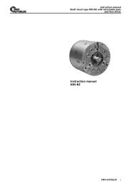
AC-BB<br />
Control unit for <strong>SP</strong> and<br />
Big Bore chucks<br />
Electropneumatic control unit for <strong>SP</strong><br />
and Big Bore ® chucks<br />
n 1/2” or 3/4” design for <strong>SP</strong> and Big Bore chucks<br />
n Actuation via foot pedal or push botton (not included in the supply range)<br />
n Clamping control via air flow sensors<br />
n Quick chuck actuation via diaphragm valves with quick exhaust<br />
n Airflow control with LED for ready and air flow. Adjustable air flow sensor sensitivity.<br />
Type Voltage Size Id. No.<br />
AC-BB 24 V 1/2” 192433<br />
AC-BB 110 V 1/2” 192448<br />
AC-BB 220 V 1/2” 192449<br />
AC-BB 24 V 3/4” 200064<br />
AC-BB 110 V 3/4” 200063<br />
AC-BB 220 V 3/4” 200062<br />
Accessories:<br />
Foot pedal F2 with 4 m cable<br />
Id. No. 013324<br />
238 <strong>SMW</strong>-AUTOBLOK<br />
Pressure switch<br />
(optional pressure transducer)<br />
Pressure adjustment with gage<br />
for clamping pressure<br />
Solenoid valves<br />
Air flow sensor<br />
Push button with 5 m cable<br />
Id. No. 192942<br />
n Electronic safety control unit<br />
n for <strong>SP</strong> and Big Bore chucks<br />
n without pressure control<br />
Air flow control for<br />
air flow sensor<br />
Standard equipment:<br />
as shown, without hoses and fittings<br />
Approx. dimensions (w x h x d)<br />
180 x 210 x 140 mm<br />
Air service unit (as spare only)<br />
Id. No. 1/2“ 192074, Id. No. 3/4“ 199790<br />
Relais
n Pneumatic diagram<br />
n Wiring diagram<br />
Pneumatic diagram AC-BB<br />
Size of all pneumatic lines min. 1/2“ or 3/4“<br />
M1<br />
DR1 0-10 bar<br />
pressure reducing<br />
valve<br />
Pneumatic power supply<br />
air connection<br />
max. pressure 10 bar<br />
Wiring diagram AC-BB<br />
constant power<br />
24 V DC<br />
110 V AC<br />
230 V AC<br />
Finder relay K1 and K2<br />
PE<br />
GND<br />
K1<br />
Y1<br />
K3<br />
K4<br />
Y1<br />
K2<br />
Y1<br />
air flow sensor B1 B2<br />
Y1<br />
S1<br />
S2<br />
SV1<br />
G1/2<br />
Clamping chuck<br />
SD1<br />
Y2<br />
Y2<br />
G1/2<br />
Y2<br />
SV2<br />
G1/8 G1/8<br />
valve valve<br />
voltage at stopped spindle only<br />
24 V DC<br />
110 V AC<br />
230 V AC<br />
A1<br />
Bartsch<br />
LSWK 17<br />
PE<br />
K1<br />
B3<br />
Bosch 0099209015<br />
pressure switch 1 - 10 bar<br />
foot pedal or push button<br />
(not included in standard<br />
supply range)<br />
air flow sensor<br />
K2<br />
K1<br />
SD2<br />
K5<br />
K6<br />
0-10 bar<br />
B3<br />
A2<br />
Bartsch<br />
LSWK 17<br />
PE<br />
at 24 VDC only<br />
B1<br />
Bartsch<br />
K17<br />
K1<br />
K2<br />
B2<br />
Bartsch<br />
K17<br />
PE<br />
Y2<br />
at 24 VDC only<br />
at 110/230 VAC<br />
only<br />
period of impulse for clamping/unclamping 1 s<br />
power ok<br />
airflow active<br />
sensitivity<br />
GREEN RED<br />
AC-BB<br />
Control unit for <strong>SP</strong> and<br />
Big Bore chucks<br />
power ok<br />
airflow active<br />
GREEN RED<br />
sensitivity<br />
pressure converter<br />
(optional)<br />
K2<br />
at 110/230 VAC<br />
only<br />
<strong>SMW</strong>-AUTOBLOK 239<br />
9