SERVICE MANUAL KSZ-DZ KSZ-AZ - SMW Autoblok
SERVICE MANUAL KSZ-DZ KSZ-AZ - SMW Autoblok
SERVICE MANUAL KSZ-DZ KSZ-AZ - SMW Autoblok

You also want an ePaper? Increase the reach of your titles
YUMPU automatically turns print PDFs into web optimized ePapers that Google loves.
<strong>KSZ</strong>-<strong>DZ</strong>, <strong>KSZ</strong>-<strong>AZ</strong> 2004-05-E<br />
Contents<br />
General safety instructions 4<br />
Structure / principle of function 5<br />
Assembly instruction 6<br />
Changing the collets<br />
with manual collet changer 7<br />
Changing the collets<br />
with pneumatic collet changer 8<br />
Technical details <strong>KSZ</strong>-<strong>DZ</strong> / <strong>KSZ</strong>-<strong>AZ</strong> 9-11<br />
Collets 12-13<br />
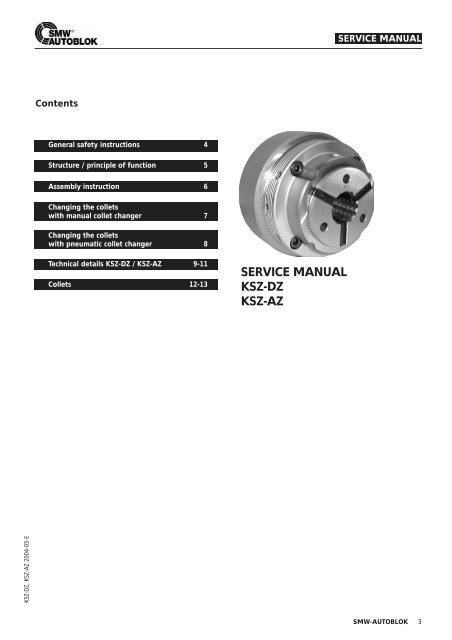
<strong>SERVICE</strong> <strong>MANUAL</strong><br />
<strong>KSZ</strong>-<strong>DZ</strong><br />
<strong>KSZ</strong>-<strong>AZ</strong><br />
<strong>SERVICE</strong> <strong>MANUAL</strong><br />
<strong>SMW</strong>-AUTOBLOK 3
General safety instructions<br />
1. Correct use<br />
<strong>SMW</strong>-AUTOBLOK power chucks work safely<br />
and troublefree if they are used according to<br />
WARNING! their specification i.e. to clamp components on<br />
turning machines.<br />
Any other use can cause hazards.<br />
WARNING!<br />
4 <strong>SMW</strong>-AUTOBLOK<br />
2. Personnel<br />
Power chucks must be installed, operated and<br />
maintained only by qualified and regularly trained<br />
personnel.<br />
3. Safety precautions to the lathe<br />
During machining the power chuck and the<br />
clamped component must be protected by<br />
WARNING! safety guards. Open machine door only when<br />
machine spindle is completely stopped. Maintenance and<br />
actuation of the power chuck must only be carried out<br />
when machine spindle is stopped.<br />
4. Technical details<br />
The max. data, max. actuating force F, max.<br />
spindle speed n are engraved on the chuck<br />
WARNING! body. They must not be exceeded. Also the<br />
summary of the total static gripping force Fsp at max.<br />
actuating force is engraved on the chuck body.<br />
5. Max. speed<br />
The max. spindle speed is only valid at max.<br />
actuating force. For special applications clam-<br />
WARNING!<br />
ping force and the max. speed must be calculated<br />
according to VDI 3106 but not exceeding the max.<br />
permitted speed.<br />
6. Remaining risks<br />
The type of components (shape, weight, unbalance,<br />
material etc.) has a big influence on the<br />
WARNING!<br />
system “machine tool - power chuck - component”.<br />
For that reason there is always a residual risk.<br />
These residual risks must be calculated by the user and have<br />
to be eliminated by suitable actions.<br />
WARNING!<br />
GENERAL SAFETY INSTRUCTIONS<br />
7. Collets<br />
Always use original-<strong>SMW</strong>-AUTOBLOK-collets.<br />
Collets of other manufacturers can cause<br />
damage to the chuck or accidents.<br />
8. Maintenance<br />
The power chuck must be maintained at regular<br />
intervals. Check the conditions by measu-<br />
WARNING!<br />
ring the gripping force with static gripmenter.<br />
Replace damaged parts with original-<strong>SMW</strong>-AUTOBLOK<br />
spare parts only.<br />
Maintenance must only be carried out at safe spindle stop<br />
of the machine!<br />
9. Actuating cylinder<br />
The actuation of the power chuck must only be<br />
carried out by suitable cylinders in accordance<br />
WARNING!<br />
with safety precautions.<br />
When installing the power chuck on the machine with an<br />
existing cylinder be sure that the actuating force of the<br />
cylinder does not exceed the max. permitted actuating<br />
force of the chuck.<br />
If necessary reduce the actuacting force of the cylinder.<br />
Connecting and adapter parts must be specified for permanent<br />
load. Adjust and check the proximity switches for<br />
the stroke control before starting the production.<br />
For any problems or questions please contact <strong>SMW</strong>-<br />
AUTOBLOK directly or one of out authorized offices.
Structure<br />
The <strong>KSZ</strong> base chuck consists of:<br />
- Base body (07) (collet seat)<br />
- Chuck flange (04)<br />
- Workstop (08/09) (<strong>KSZ</strong>-<strong>AZ</strong> only)<br />
- Mounting material<br />
STRUCTURE / PRINCIPLE OF FUNCTION<br />
The <strong>KSZ</strong> to pull type chuck can be used for bar work (<strong>KSZ</strong>-<strong>DZ</strong>) or with workstop for bar and chuck work (<strong>KSZ</strong>-<strong>AZ</strong>).<br />
01<br />
02<br />
01 machine spindle<br />
02 draw tube<br />
03 adapter<br />
Principle of function<br />
04 chuck flange<br />
05 draw piston<br />
06 draw sleeve<br />
03 04<br />
05 06 07<br />
10<br />
09<br />
08<br />
04<br />
06 07<br />
<strong>KSZ</strong>-<strong>AZ</strong> <strong>KSZ</strong>-<strong>DZ</strong><br />
07 base body<br />
08 workstop base (<strong>KSZ</strong>-<strong>AZ</strong> only)<br />
09 workstop (<strong>KSZ</strong>-<strong>AZ</strong> only)<br />
10 collet<br />
By pulling the draw tube (02) the collet (10) is pulled against the taper of the base body (07). This axial movement will cause<br />
the collet to close, and thus clamp the workpiece.<br />
10<br />
<strong>SMW</strong>-AUTOBLOK 5
Assembly instruction<br />
02<br />
01 machine spindle<br />
02 draw tube<br />
03 adapter<br />
Disassembling of <strong>KSZ</strong> collet chuck<br />
By removing the mounting bolts (11) the chuck flange (04)<br />
and the base body (07) can be separated. The mounting<br />
bolts (12) remain tightened. In case these bolts are opened<br />
they have to be remounted and thightened with<br />
a torque of 10 Nm (at <strong>KSZ</strong>-<strong>AZ</strong> only).<br />
Mounting of the chuck flange (04)<br />
Check the radial and axial accuracy of the machine spindle.<br />
These values should not exceed 5 µm to allow accurate<br />
machining with the collet chuck.<br />
Clean the mounting faces of the machine spindle (01) and<br />
the chuck before assembling. Put the chuck flange (04)<br />
onto the machine spindle (01), orientate and tighten the<br />
mounting bolts (10) according to the specification of the<br />
machine manufacturer.<br />
6 <strong>SMW</strong>-AUTOBLOK<br />
01 03 04<br />
12<br />
04 chuck flange<br />
05 draw piston<br />
06 collet sleeve<br />
10 05<br />
07 base body<br />
08 workstop base<br />
09 workstop<br />
Mounting of the base chuck body (05-07)<br />
06<br />
ASSEMBLY<br />
Reduce the actuating force for the actuating cylinder to the<br />
lowest value possible. Bring the draw tube (02) to its complete<br />
forward (right) end position. Mount the adapter (03)<br />
(optional: has to be machined according to the machine<br />
specification). Screw the draw piston (05) together with the<br />
base body (07) and the workstop base (08) (at <strong>KSZ</strong>-<strong>AZ</strong> only)<br />
completely onto the draw tube assembly (02/03). Orientate<br />
the through holes of the bolts (11) of the base body assembly<br />
(05-07) to the tapped holes of the chuck flange (04).<br />
Pull the draw tube at lowest force possible backward (left<br />
direction) and assemble the base body assembly into the<br />
chuck flange (04). Tighten the mounting bolts (11).<br />
Check radial and face runout<br />
Put a dial indicator onto the face of the base body (07) and<br />
check the face runout. To check the radial concentricity put<br />
the dial indicator onto the Id taper. Within the clearance of<br />
the parts the radial runout of the base body can be fine<br />
adjusted. In case the runout cannot be adjusted to less<br />
than 10 µm the chuck has to be disassembled once more<br />
and checked for contamination or damage. Repeat the<br />
assembly process until you reach a runout of less than 10<br />
µm.<br />
11<br />
07<br />
10 mounting bolt<br />
11 mounting bolt<br />
12 mounting bolt<br />
09<br />
08
Changing the collets with manual collet changer<br />
11<br />
01 adapter<br />
02 workstop base<br />
03 locking bolt<br />
Insert the collet<br />
To insert the collet open the chuck (right end position of<br />
the draw tube).<br />
Clean the collet (07) and the taper of the base body (05).<br />
Insert the pins of the changing unit (08) into the bores of<br />
the collet (07) completely. Turn the handle clockwise until<br />
the segments of the collet (07) touch each other. In case<br />
the rubber elements interfere during mounting rotate the<br />
handle back counter-clockwise by one revolution.<br />
Insert the collet (07) into be base body (05) so that a slot of<br />
a collet segment matches the position of the orientation<br />
bolt (06). Push the changing unit lightly towards the chuck<br />
and open the handle completely in counter-clockwise<br />
direction.<br />
Removing the collet<br />
Removing the collet is only possible in chuck opened position<br />
(right end position).<br />
Insert the pins of the changing unit (08) into the bores of<br />
the collet (07) completely. Rotate the hand wheel clockwise<br />
until the collet (07) is collapsed completely. Pull out the<br />
collet (07) from the chuck. Open the changing unit (08)<br />
counter-clockwise and remove the collet.<br />
CHANGING THE COLLECTS WITH <strong>MANUAL</strong> COLLET CHANGER<br />
01 02 03 04 05 06 07 08 09 10<br />
04 workstop<br />
05 base body<br />
06 orientation bolt<br />
07 collet<br />
08 manual changer<br />
09 protection ring<br />
10 bolt M12<br />
11 orientation pin<br />
Removing the workstop (04) (at <strong>KSZ</strong>-<strong>AZ</strong> only)<br />
The collet (07) must be removed.<br />
The 3 locking bolts (03) have to be opened so that the<br />
workstop (04) can be removed by pulling it out with the<br />
bolt (10).<br />
Clean the inside of the chuck body thoroughly and insert<br />
the protection ring (09). Tighten the locking bolts (03). The<br />
Id thread M12 of the workstop (04) can be used to mount<br />
workpiece specific workstops. It also can be remachined.<br />
The front tapped holes at the base body (05) can be used<br />
to mount a front workstop.<br />
<strong>SMW</strong>-AUTOBLOK 7
Connecting the collet changer to a air service<br />
unit<br />
Connect the pneumatic changer to a air service unit consisting<br />
of filter, pressure regulator and oiler.<br />
The pneumatic port (10) is a 1/4 thread. Standard fittings<br />
can be adapted. The Id of the pneumatic hose must be bigger<br />
than 6 mm.<br />
Use an oil resistant PVC textile reinforced hose as pneumatic<br />
line. The oil level in the air service unit has to be checked<br />
periodically. Use the pneumatic changer with oiled air only<br />
(danger of corrosion).<br />
The pressure for the pneumatic changing unit of the sizes<br />
32, 42 and 65 has to be adjusted to 4-5 bar. The pressure<br />
for the pneumatic changing unit for size 100 has to be<br />
adjusted to 8 bar.<br />
Attention: Hoses and the fittings have to be mounted properly.<br />
Danger of injury!<br />
Function<br />
When the push button (09) is pressed air actuates the builtin<br />
piston. The piston moves and actuates the lever system<br />
that will actuate the pins towards an end stop. When you<br />
releasing the push button the built-in spring will push the<br />
piston back into its original position. The pins will open to<br />
their complete open end position.<br />
8 <strong>SMW</strong>-AUTOBLOK<br />
CHANGING THE COLLETS WITH PNEUMATIC COLLET CHANGER<br />
Changing collets with pneumatic collet changer<br />
01 adapter<br />
02 workstop base<br />
03 locking bolt<br />
01<br />
02 03 04 05 06 07 08<br />
04 workstop<br />
05 base body<br />
06 orientation bolt<br />
09<br />
10<br />
07 collet<br />
08 pneumatic changer<br />
09 push button<br />
Mounting of a collet<br />
Mounting of a collet is only possible in chuck open position<br />
(right end position).<br />
Clean the collet (07) and the taper of the base body (05)<br />
thoroughly.<br />
Insert the pins of the changing unit (08) into the bores of<br />
the collet (07) completely. Push the push button (09). This<br />
will cause the pneumatic changing unit and thus the collet<br />
to collapse.<br />
Insert the collet (07) into the base body (05) completely.<br />
Observe that a slot of a collet segment matches the position<br />
of the orientation bolt (06). Push slightly against the<br />
chuck body and release the push button. Remove the<br />
pneumatic changing unit.<br />
Removing a collet<br />
10 pneumatic port<br />
Removing a collet is possible in chuck open position only<br />
(right end position).<br />
Insert the pins of the changing unit (08) into the bores of<br />
the collet (07) completely. Actuate the push button (09).<br />
This will cause the pins of the pneumatic changing unit (07)<br />
and thus the collet to collapse. Pull out the collet with the<br />
changing unit from the chuck.<br />
Release the push button and remove the collet.
TECHNICAL DETAILS <strong>KSZ</strong>-<strong>DZ</strong> / <strong>KSZ</strong>-<strong>AZ</strong><br />
Application/customer’s benefit<br />
■ Safe clamping of bars and shafts<br />
■ Quick change of collets with changing unit<br />
■ Changing unit manual or pneumatic<br />
■ Direct mounting of the collets into the body<br />
ensures highest concentricity<br />
■ Collets available round, square, hexagonal or as<br />
blanks to be machined on the chuck<br />
■ Available for stationary use<br />
<strong>KSZ</strong>-<strong>DZ</strong><br />
■ Safe clamping of bars<br />
■ No pressure forces onto the machine spindle<br />
during clamping<br />
■ Highest axial and radial rigidity with draw collet<br />
system<br />
■ Parallel clamping of the collets<br />
■ Flexible use because of large range of the collets<br />
<strong>KSZ</strong>-<strong>AZ</strong><br />
■ Rigid axial workstop for shafts<br />
■ High axial positioning accuracy of the shafts<br />
because of pull down effect onto the workstop<br />
■ Full through hole available because of quick<br />
change of axial workstop<br />
■ Special workstops available on request<br />
<strong>SMW</strong>-AUTOBLOK 9
Chuck in open position<br />
Subject to technical changes<br />
<strong>SMW</strong>-AUTOBLOK Type<br />
Mounting<br />
Id. No.<br />
max. speed r.p.m.<br />
max. actuating force<br />
max. gripping force<br />
Weight without<br />
collets<br />
rec. actuating cylinders Type<br />
Speed r.p.m.<br />
10 <strong>SMW</strong>-AUTOBLOK<br />
TECHNICAL DETAILS <strong>KSZ</strong>-<strong>DZ</strong><br />
<strong>KSZ</strong>-<strong>DZ</strong> 42 <strong>KSZ</strong>-<strong>DZ</strong> 65<br />
Z140 A5 A6 Z170 A5 A6 A8<br />
193234 192154 192155 193235 192156 192157 192158<br />
A 150 140 165 185/160 150 165 210<br />
B 125 124 124 145 140 140 140<br />
C 98 98 98 120 120 120 120<br />
D M 66 x 1.5 M66 x 1.5 M66 x 1.5 M 78 x 1.5 M78 x 1.5 M78 x 1.5 M78 x 1.5<br />
E 43 43 43 67 67 67 67<br />
F 90 90 90 95 95 95 100<br />
G 68.5 68.5 68.5 68.5 68.5 68.5 73.5<br />
H 45 45 45 45 45 45 50<br />
I - 41.5 41.5 - 41.5 41.5 46.5<br />
I1 35.5 - - 35.5 - - -<br />
K 17.5 17.5 17.5 17.5 17.5 17.5 17.5<br />
P H6 140 170<br />
R 104.8 3x120° M10 - - 133.4 6x60° M12 - - -<br />
7000 7000 7000 6000 6000 6000 4000<br />
daN 3500 3500 3500 4500 4500 4500 4500<br />
daN 8000 8000 8000 10500 10500 10500 10500<br />
kg 7.0 6.0 7.2 14.8 10.8 13.0 17.2<br />
Ordering review<br />
Supply range: Chuck and mounting bolts<br />
Changing unit<br />
VNK 102-46 VNK 102-46 VN 102-46 VNK 150-67 VNK 150-67 VNK 150-67 VNK 150-67<br />
8000 8000 8000 5500 5500 5500 5500<br />
Size<br />
Spindle mounting<br />
A 05<br />
A 06<br />
A 08<br />
Accessories<br />
manual<br />
pneumatic<br />
Size<br />
<strong>KSZ</strong>-<strong>DZ</strong> 42 <strong>KSZ</strong>-<strong>DZ</strong> 65<br />
192154 192156<br />
192155 192157<br />
- 192158<br />
<strong>KSZ</strong>-<strong>DZ</strong> 42 <strong>KSZ</strong>-<strong>DZ</strong> 65<br />
192150 192152<br />
192151 192153
Chuck in open position<br />
Subject to technical changes<br />
<strong>SMW</strong>-AUTOBLOK Type<br />
Mounting<br />
Id. No.<br />
max. speed r.p.m.<br />
max. actuating force<br />
max. gripping force<br />
Mass without<br />
collets<br />
rec. actuating cylinders Type<br />
Speed r.p.m.<br />
Spindle mounting<br />
Z 140<br />
Z 170<br />
A 05<br />
A 06<br />
A 08<br />
TECHNICAL DETAILS <strong>KSZ</strong>-<strong>AZ</strong><br />
<strong>KSZ</strong>-<strong>AZ</strong> 42 <strong>KSZ</strong>-<strong>AZ</strong> 65<br />
Z140 A5 A6 Z170 A5 A6 A8<br />
192951 192145 192146 193228 192147 192148 192149<br />
A 150 140 165 185 155 165 210<br />
B 125 125 125 145 145 145 145<br />
C 98 98 98 120 120 120 120<br />
D M78 x 1.5 M78 x 1.5 M78 x 1.5 M78 x 1.5 M78 x 1.5 M78 x 1.5 M78 x 1.5<br />
E 43 43 43 66 66 66 66<br />
F 126 121 121 130 130 130 135<br />
G 110.5 105.5 105.5 111.5 111.5 111.5 116.5<br />
H 75 70 70 70.5 70.5 70.5 75.5<br />
I - 41.5 41.5 - 41.5 41.5 46.5<br />
I1 40.5 - - 35.5 - - -<br />
K 17.5 17.5 17.5 17.5 17.5 17.5 17.5<br />
L 46 46 46 55 55 55 55<br />
Mg5 49 49 49 72 72 72 72<br />
N 21 21 21 20.5 20.5 20.5 20.5<br />
O M12 M12 M12 M12 M12 M12 M12<br />
P H6 140 - - 170 - - -<br />
R 104.8 3 x 120° M10 - - 133.4 6 x 60° M12 - - -<br />
7000 7000 7000 6000 6000 6000 4000<br />
daN 3500 3500 3500 4500 4500 4500 4500<br />
daN 8000 8000 8000 10500 10500 10500 10500<br />
kg 7.8 7.2 8.5 18.0 12.9 15.4 20.4<br />
Ordering review<br />
Supply range: Chuck and mounting bolts<br />
Changing unit/Boring ring<br />
Accessories<br />
manual<br />
pneumatic<br />
VNK 102-46 VNK 102-46 VNK 102-46 VNK 150-67 VNK 150-67 VNK 150-67 VNK 150-67<br />
8000 8000 8000 5500 5500 5500 5500<br />
Size<br />
Size<br />
<strong>KSZ</strong>-<strong>AZ</strong> 42 <strong>KSZ</strong>-<strong>AZ</strong> 65<br />
192951 -<br />
- 193228<br />
192145 192147<br />
192146 192148<br />
- 192149<br />
<strong>KSZ</strong>-<strong>AZ</strong> 42 <strong>KSZ</strong>-<strong>AZ</strong> 65<br />
192150 192152<br />
192151 192153<br />
<strong>SMW</strong>-AUTOBLOK 11
Collets for <strong>KSZ</strong>-<strong>DZ</strong> 42/<strong>KSZ</strong>-<strong>AZ</strong> 42/<strong>KSZ</strong>-NZ 42<br />
Steel collets with axial and radial grooves (* smooth, ** radial grooves)<br />
ROUND ¹<br />
12 <strong>SMW</strong>-AUTOBLOK<br />
COLLETS<br />
Ø 4* 5* 6* 7* 8** 9** 10** 11 12 13 14 15 16<br />
Id. No. 192173 192174 192175 192176 192177 192178 192179 192180 192181 192182 192183 192184 192185<br />
Ø 17 18 19 20 21 22 23 24 25 26 27 28 29<br />
Id. No. 192186 192187 192188 192189 192190 192191 192192 192193 192194 192195 192196 192197 192198<br />
Ø 30 31 32 33 34 35 36 37 38 39 40 41 42<br />
Id. No. 192199 192200 192201 192202 192203 192204 192205 192206 192207 192208 192209 192210 192211<br />
Steel collets with smooth clamping surface<br />
ROUND ¹<br />
Ø 4 5 6 7 8 9 10 11 12 13 14 15 16<br />
Id. No. 192173 192174 192175 192176 193135 193136 193137 193138 193139 193140 193141 193142 193143<br />
Ø 17 18 19 20 21 22 23 24 25 26 27 28 29<br />
Id. No. 193144 192807 193145 192808 193146 193147 193148 193149 193150 193151 193152 193153 193154<br />
Ø 30 31 32 33 34 35 36 37 38 39 40 41 42<br />
Id. No. 193155 193156 193083 193157 193158 193159 193160 193161 193162 193163 193164 193165 193219<br />
SQUARE ¹¹<br />
Id. No.<br />
Id. No.<br />
7* 8** 9** 10** 11** 12** 13** 14** 15** 16** 17** 18** 19**<br />
192212 192213 192214 192215 192216 192217 192218 192219 192220 192221 192222 192223 192224<br />
20** 21** 22** 23** 24** 25** 26** 27** 28** 29** 30**<br />
192225 192226 192227 192228 192229 192230 192231 192232 192233 192234 192235<br />
HEXAGONAL<br />
7* 8** 9** 10** 11** 12** 13** 14** 15** 16** 17** 18** 19**<br />
Id. No. 192236 192237 192238 192239 192240 192241 192242 192243 192244 192245 192246 192247 192248<br />
20** 21** 22** 23** 24** 25** 26** 27** 28** 29** 30** 31** 32**<br />
Id. No. 192249 192250 192251 192252 192253 192254 192255 192256 192257 192258 192259 192260 192261<br />
¹¹<br />
Soft steel collets (pre-bored)<br />
Round<br />
Ø 5 15 30<br />
Id. No. 192262 192263 192264<br />
Boring ring 42 for soft steel collets<br />
Id. No.<br />
193399<br />
¹<br />
concentricity similar DIN 6343<br />
¹¹<br />
concentricity has to be agreed
Collets for <strong>KSZ</strong>-<strong>DZ</strong> 65/<strong>KSZ</strong>-<strong>AZ</strong> 65/<strong>KSZ</strong>-NZ 65<br />
Steel collets with axial and radial grooves (* smooth, ** radial grooves)<br />
ROUND ¹<br />
COLLETS<br />
Ø 5* 6* 7* 8** 9** 10** 11 12 13 14 15 16 17<br />
Id. No. 192265 192266 192267 192268 192269 192270 192271 192272 192273 192274 192275 192276 192277<br />
Ø 18 19 20 21 22 23 24 25 26 27 28 29 30<br />
Id. No. 192278 192279 192280 192281 192282 192283 192284 192285 192286 192287 192288 192289 192290<br />
Ø 31 32 33 34 35 36 37 38 39 40 41 42 43<br />
Id. No. 192291 192292 192293 192294 192295 192296 192297 192298 192299 192300 192301 192302 192303<br />
Ø 44 45 46 47 48 49 50 51 52 53 54 55 56<br />
Id. No. 192304 192305 192306 192307 192308 192309 192310 192311 192312 192313 192314 192315 192316<br />
Ø 57 58 59 60 61 62 63 64 65<br />
Id. No. 192317 192318 192319 192320 192321 192322 192323 192324 192325<br />
Steel collets with smooth clamping surface<br />
ROUND ¹<br />
Ø 5 6 7 8 9 10 11 12 13 14 15 16 17<br />
Id. No. 192265 192266 192267 193172 193173 192682 193174 192787 193175 193176 193177 193169 193178<br />
Ø 18 19 20 21 22 23 24 25 26 27 28 29 30<br />
Id. No. 193179 193180 193181 193182 192683 193183 193170 193065 193184 193066 193068 193069 193070<br />
Ø 31 32 33 34 35 36 37 38 39 40 41 42 43<br />
Id. No. 193185 192684 193186 193187 193188 193189 193190 193191 193192 192685 193193 193194 193171<br />
Ø 44 45 46 47 48 49 50 51 52 53 54 55 56<br />
Id. No. 193196 193197 193198 193199 193200 193201 193202 193203 193204 193205 193206 193207 193208<br />
Ø 57 58 59 60 61 62 63 64 65<br />
Id. No. 193195 193209 193210 193211 193212 193213 193214 193215 193216<br />
SQUARE ¹¹<br />
Id. No.<br />
Id. No.<br />
Id. No.<br />
8** 9** 10** 11** 12** 13** 14** 15** 16** 17** 18** 19** 20**<br />
192326 192327 192328 192329 192330 192331 192332 192333 192334 192335 192336 192337 192338<br />
21** 22** 23** 24** 25** 26** 27** 28** 29** 30** 31** 32** 33**<br />
192339 192340 192341 192342 192343 192344 192345 192346 192347 192348 192349 192350 192351<br />
34** 35** 36** 37** 38** 39** 40** 41** 42** 43** 44** 45** 46**<br />
192352 192353 192354 192355 192356 192357 192358 192359 192360 192361 192362 192363 192364<br />
HEXAGONAL<br />
10** 11** 12** 13** 14** 15** 16** 17** 18** 19** 20** 21** 22**<br />
192365 192366 192367 192368 192369 192370 192371 192372 192373 192374 192375 192376 192377<br />
23** 24** 25** 26** 27** 28** 29** 30** 31** 32** 33** 34** 35**<br />
192378 192379 192380 192381 192382 192383 192384 192385 192386 192387 192388 192389 192390<br />
36** 37** 38** 39** 40** 41** 42** 43** 44** 45** 46** 47** 48**<br />
192391 192392 192393 192394 192395 192396 192397 192398 192399 192400 192401 192402 192403<br />
49** 50**<br />
192404 192405<br />
¹¹<br />
Id. No.<br />
Id. No.<br />
Id. No.<br />
Id. No.<br />
Soft steel collets (pre-bored)<br />
ROUND<br />
Ø 8 20 40<br />
Id. No. 192406 192407 192408<br />
Boring ring 65 for soft steel collets<br />
Id. No.<br />
193400<br />
¹ concentricity similar DIN 6343<br />
¹¹ concentricity has to be agreed<br />
<strong>SMW</strong>-AUTOBLOK 13