SERVICE MANUAL KSZ-DZ KSZ-AZ - SMW Autoblok
SERVICE MANUAL KSZ-DZ KSZ-AZ - SMW Autoblok
SERVICE MANUAL KSZ-DZ KSZ-AZ - SMW Autoblok

Create successful ePaper yourself
Turn your PDF publications into a flip-book with our unique Google optimized e-Paper software.
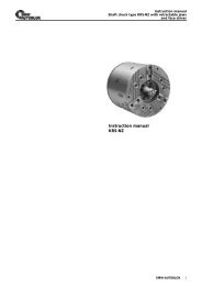
Assembly instruction<br />
02<br />
01 machine spindle<br />
02 draw tube<br />
03 adapter<br />
Disassembling of <strong>KSZ</strong> collet chuck<br />
By removing the mounting bolts (11) the chuck flange (04)<br />
and the base body (07) can be separated. The mounting<br />
bolts (12) remain tightened. In case these bolts are opened<br />
they have to be remounted and thightened with<br />
a torque of 10 Nm (at <strong>KSZ</strong>-<strong>AZ</strong> only).<br />
Mounting of the chuck flange (04)<br />
Check the radial and axial accuracy of the machine spindle.<br />
These values should not exceed 5 µm to allow accurate<br />
machining with the collet chuck.<br />
Clean the mounting faces of the machine spindle (01) and<br />
the chuck before assembling. Put the chuck flange (04)<br />
onto the machine spindle (01), orientate and tighten the<br />
mounting bolts (10) according to the specification of the<br />
machine manufacturer.<br />
6 <strong>SMW</strong>-AUTOBLOK<br />
01 03 04<br />
12<br />
04 chuck flange<br />
05 draw piston<br />
06 collet sleeve<br />
10 05<br />
07 base body<br />
08 workstop base<br />
09 workstop<br />
Mounting of the base chuck body (05-07)<br />
06<br />
ASSEMBLY<br />
Reduce the actuating force for the actuating cylinder to the<br />
lowest value possible. Bring the draw tube (02) to its complete<br />
forward (right) end position. Mount the adapter (03)<br />
(optional: has to be machined according to the machine<br />
specification). Screw the draw piston (05) together with the<br />
base body (07) and the workstop base (08) (at <strong>KSZ</strong>-<strong>AZ</strong> only)<br />
completely onto the draw tube assembly (02/03). Orientate<br />
the through holes of the bolts (11) of the base body assembly<br />
(05-07) to the tapped holes of the chuck flange (04).<br />
Pull the draw tube at lowest force possible backward (left<br />
direction) and assemble the base body assembly into the<br />
chuck flange (04). Tighten the mounting bolts (11).<br />
Check radial and face runout<br />
Put a dial indicator onto the face of the base body (07) and<br />
check the face runout. To check the radial concentricity put<br />
the dial indicator onto the Id taper. Within the clearance of<br />
the parts the radial runout of the base body can be fine<br />
adjusted. In case the runout cannot be adjusted to less<br />
than 10 µm the chuck has to be disassembled once more<br />
and checked for contamination or damage. Repeat the<br />
assembly process until you reach a runout of less than 10<br />
µm.<br />
11<br />
07<br />
10 mounting bolt<br />
11 mounting bolt<br />
12 mounting bolt<br />
09<br />
08