LYN300 LYN400 - liftmaster.de
LYN300 LYN400 - liftmaster.de
LYN300 LYN400 - liftmaster.de

Create successful ePaper yourself
Turn your PDF publications into a flip-book with our unique Google optimized e-Paper software.
PLEASE START BY READING THESE IMPORTANT SAFETY RULES • SAVE THESE INSTRUCTIONS<br />
This safety alert symbol means "Caution" - failure to comply with such an instruction involves risk of personal<br />
injury or damage to property. Please read these warnings carefully.<br />
This gate drive mechanism is <strong>de</strong>signed and tested to offer appropriately safe service provi<strong>de</strong>d it is installed and<br />
operated in strict accordance with the following safety rules.<br />
Incorrect installation and/or failure to comply with the following instructions may result in serious personal injury<br />
or property damage.<br />
When using tools and small parts to install or<br />
carry out repair work on a gate exercise caution<br />
and do not wear rings, watches or loose<br />
clothing.<br />
Installation and wiring must be in compliance<br />
with your local building and electrical installation<br />
co<strong>de</strong>s. Power cables must only be connected to<br />
a properly earthed supply.<br />
Any entrapment possibility by the moving wing<br />
between wing & walls must be secured with<br />
safety edges or IR-sensors.<br />
Please remove any locks fitted to the gate in or<strong>de</strong>r<br />
to prevent damage to the gate.<br />
After the installation a final test of the full<br />
function of the system and the full function of the<br />
safety <strong>de</strong>vices must be done.<br />
This drive cannot be used with a gate<br />
incorporating a wicket door unless the drive<br />
cannot be operated with the wicket door open.<br />
Contents: General advice on<br />
installation and use:<br />
Contents list: page 1<br />
Content of the carton: page 1, figure<br />
Before you begin: page 1<br />
Checklist: page 2<br />
Gate types/installation height:<br />
page 2, figure 2<br />
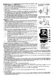
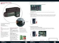
CONTENT OF THE CARTON<br />
(1) Motor (1)<br />
(2) Postbracket (1)<br />
(3) Keys (2)<br />
Gate configuration:<br />
page 2, figure 3<br />
Gate stops:<br />
page 2, figure 4<br />
Post bracket/Gate fixing bracket:<br />
page 2, figure 5 A-D<br />
Release of drive arms:<br />
page 3, figure 6<br />
BEFORE YOU BEGIN<br />
The drive mechanism needs room to the si<strong>de</strong> permitting<br />
correct installation of drive arms. Please make sure that this<br />
is available. Gates affected by high wind loads must also be<br />
protected by an (electric) lock.<br />
There are many factors to consi<strong>de</strong>r when choosing the right<br />
drive mechanism. Assuming that a gate functions properly,<br />
"startup" is the most difficult phase, once the gate is in motion,<br />
significantly less force is usually required to move it.<br />
• Gate size: Gate size is a very important factor. Wind can<br />
brake or distort the gate, thereby increasing the amount of<br />
force nee<strong>de</strong>d to move it consi<strong>de</strong>rably.<br />
• Gate weight: The weight of the gate in not as relevant as<br />
the size.<br />
709226B-GB - 05.2004<br />
1<br />
1<br />
It is important to make sure that the gate always<br />
runs smoothly. Gates which stick or jam must be<br />
repaired immediately. Employ a qualified<br />
technician to repair the gate, never attempt to<br />
repair it yourself.<br />
Keep additional accessories away from children. Do<br />
not allow children to play with pushbuttons or remote<br />
controls. A gate can cause serious injuries as it<br />
closes.<br />
Disconnect electric power to the system before<br />
making repairs or removing covers.<br />
Make sure that people who install, maintain or<br />
operate the gate drive follow these instructions.<br />
Keep these instructions in a safe place so that you<br />
can refer to them quickly when you need to.<br />
The full protection against potential squeeze or<br />
entrappment must work direct when the drive<br />
arms are installed.<br />
(4) Gate fixing bracket (1)<br />
(5) Con<strong>de</strong>nsator (1)<br />
(6) Manual (1)<br />
(7) Clevis pin (2) and Rings (4)<br />
Installing the drive arms:<br />
page 3, figure 7<br />
Wiring: page 3, figure 7 B<br />
Initial operation: page 3<br />
Maintenance work: page 3<br />
Warranty: page 3<br />
Technical data: page 3<br />
CE Declaration of Conformity: page 3<br />
BEFORE YOU BEGIN (CONTINUED)<br />
• Effect of temperature: Low outdoor temperatures can<br />
make initial startup more difficult (changes in the ground,<br />
etc.) or even prevent it. High outdoor temperatures along<br />
with frequent use can trigger thermal protection<br />
prematurely (approx. 135 ºC).<br />
• Operating frequency/operating time: Drive mechanisms<br />
are <strong>de</strong>signed for a maximum operating time (running time)<br />
of approximately 30% (e.g. 30% during any one hour).<br />
IMPORTANT: The drive mechanism is not <strong>de</strong>signed to<br />
operate continuously at its maximum operating time (nonstop<br />
operation). Otherwise the drive mechanism becomes<br />
too hot and switches off until it cools down to the switch-on<br />
temperature. The outdoor temperature and the gate are<br />
important parameters that affect the actual operating time.<br />
1-GB