Mystique RES 2.9m ARF - Horizon Hobby UK
Mystique RES 2.9m ARF - Horizon Hobby UK
Mystique RES 2.9m ARF - Horizon Hobby UK

You also want an ePaper? Increase the reach of your titles
YUMPU automatically turns print PDFs into web optimized ePapers that Google loves.
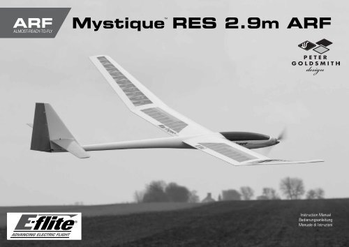
<strong>ARF</strong><br />
ALMOST-READY-TO-FLY<br />
<strong>Mystique</strong><br />
<br />
<strong>RES</strong> <strong>2.9m</strong> <strong>ARF</strong><br />
Instruction Manual<br />
Bedienungsanleitung<br />
Manuale di Istruzioni<br />
1
NOTICE<br />
All instructions, warranties and other collateral documents are subject to change at the sole discretion of <strong>Horizon</strong><br />
<strong>Hobby</strong>, Inc. For up-to-date product literature, visit horizonhobby. com and click on the support tab for this product.<br />
Meaning of Special Language<br />
The following terms are used throughout the product literature to indicate various levels of potential harm when<br />
operating this product:<br />
NOTICE: Procedures, which if not properly followed, create a possibility of physical property damage AND a little<br />
or no possibility of injury.<br />
CAUTION: Procedures, which if not properly followed, create the probability of physical property damage AND a<br />
possibility of serious injury.<br />
WARNING: Procedures, which if not properly followed, create the probability of property damage, collateral<br />
damage, and serious injury OR create a high probability of superficial injury.<br />
WARNING: Read the ENTIRE instruction manual to become familiar with the features of the product<br />
before operating. Failure to operate the product correctly can result in damage to the product, personal<br />
property and cause serious injury.<br />
This is a sophisticated hobby product. It must be operated with caution and common sense and requires some<br />
basic mechanical ability. Failure to operate this Product in a safe and responsible manner could result in injury<br />
or damage to the product or other property. This product is not intended for use by children without direct adult<br />
supervision. Do not use with incompatible components or alter this product in any way outside of the instructions<br />
provided by <strong>Horizon</strong> <strong>Hobby</strong>, Inc. This manual contains instructions for safety, operation and maintenance. It is<br />
essential to read and follow all the instructions and warnings in the manual, prior to assembly, setup or use, in<br />
order to operate correctly and avoid damage or serious injury.<br />
Safety warnings and precautions<br />
Read and follow all instructions and safety precautions<br />
before use. Improper use can result in fire, serious injury<br />
and damage to property.<br />
Components<br />
Use only with compatible components. Should any<br />
compatibility questions exist, please refer to the product<br />
instructions, component instructions or contact the<br />
appropriate <strong>Horizon</strong> <strong>Hobby</strong> office.<br />
Flight<br />
Fly only in open areas to ensure safety. It is<br />
recommended flying be done at radio control flying<br />
fields. Consult local ordinances before choosing a flying<br />
location.<br />
Propeller<br />
Keep loose items that can become entangled in<br />
the propeller away from the prop. This includes<br />
loose clothing or other objects such as pencils and<br />
screwdrivers. Keep your hands away from the propeller<br />
as injury can occur.<br />
Batteries<br />
Always follow the manufacturer’s instructions when using<br />
and disposing of any batteries. Mishandling of Li-Po<br />
batteries can result in fire causing serious injury and<br />
damage.<br />
Small Parts<br />
This kit includes small parts and should not be left<br />
unattended near children as choking and serious injury<br />
could result.<br />
Safe operating recommendations<br />
• Inspect your model before every flight to ensure it is<br />
airworthy.<br />
• Be aware of any other radio frequency user who may<br />
present an interference problem.<br />
• Always be courteous and respectful of other users in<br />
your selected flight area.<br />
• Choose an area clear of obstacles and large enough to<br />
safely accomodate your flying activity.<br />
• Make sure this area is clear of friends and spectators<br />
prior to launching your aircraft.<br />
• Be aware of other activities in the vicinity of your flight<br />
path that could cause potential conflict.<br />
• Carefully plan your flight path prior to launch.<br />
• Abide by any and all established AMA National Model<br />
Aircraft Safety Code.<br />
Age Recommendation: Not for children under 14 years. This is not a toy.<br />
Using the Manual<br />
This manual is divided into sections to help make assembly easier to understand. Boxes () have been placed next<br />
to each step. These help keep track of steps that have been completed.<br />
2
HINWEIS<br />
Alle Anweisungen, Garantien und anderen zugehörigen Dokumente können im eigenen Ermessen von <strong>Horizon</strong><br />
<strong>Hobby</strong>, Inc. jederzeit geändert werden. Die aktuelle Produktliteratur finden Sie auf horizonhobby.com unter der<br />
Registerkarte „Support“ für das betreffende Produkt.<br />
Spezielle Bedeutungen<br />
Die folgenden Begriffe werden in der gesamten Produktliteratur verwendet, um auf unterschiedlich hohe<br />
Gefahrenrisiken beim Betrieb dieses Produkts hinzuweisen:<br />
HINWEIS: Wenn diese Verfahren nicht korrekt befolgt werden, können sich möglicherweise Sachschäden UND<br />
geringe oder keine Gefahr von Verletzungen ergeben.<br />
ACHTUNG: Wenn diese Verfahren nicht korrekt befolgt werden, ergeben sich wahrscheinlich Sachschäden UND<br />
die Gefahr von schweren Verletzungen.<br />
WARNUNG: Wenn diese Verfahren nicht korrekt befolgt werden, ergeben sich wahrscheinlich Sachschäden,<br />
Kollateralschäden und schwere Verletzungen ODER mit hoher Wahrscheinlichkeit oberflächliche Verletzungen.<br />
WARNUNG: Lesen Sie die GESAMTE Bedienungsanleitung, um sich vor dem Betrieb mit den<br />
Produktfunktionen vertraut zu machen. Wird das Produkt nicht korrekt betrieben, kann dies zu Schäden am<br />
Produkt oder persönlichem Eigentum führen oder schwere Verletzungen verursachen.<br />
Dies ist ein hochentwickeltes <strong>Hobby</strong>-Produkt. Es muss mit Vorsicht und gesundem Menschenverstand betrieben<br />
werden und benötigt gewisse mechanische Grundfähigkeiten. Wird dieses Produkt nicht auf eine sichere und<br />
verantwortungsvolle Weise betrieben, kann dies zu Verletzungen oder Schäden am Produkt oder anderen<br />
Sachwerten führen. Dieses Produkt eignet sich nicht für die Verwendung durch Kinder ohne direkte Überwachung<br />
eines Erwachsenen. Verwenden Sie das Produkt nicht mit inkompatiblen Komponenten oder verändern es in<br />
jedweder Art ausserhalb der von <strong>Horizon</strong> <strong>Hobby</strong>, Inc. vorgegebenen Anweisungen. Diese Bedienungsanleitung<br />
enthält Anweisungen für Sicherheit, Betrieb und Wartung. Es ist unbedingt notwendig, vor Zusammenbau,<br />
Einrichtung oder Verwendung alle Anweisungen und Warnhinweise im Handbuch zu lesen und zu befolgen, damit es<br />
bestimmungsgemäß betrieben werden kann und Schäden oder schwere Verletzungen vermieden werden.<br />
Nicht geeignet für Kinder unter 14 Jahren. Dies ist kein Spielzeug.<br />
Warnungen und Sicherheitsvorkehrungen<br />
Bitte lesen und befolgen Sie alle Anweisungen und<br />
Sichervorkehrungen vor dem Gebrauch. Falscher,<br />
nicht sachgemäßer Gebrauch kann Feuer, ernsthafte<br />
Verletzungen und Sachbeschädigungen zur Folge haben.<br />
Komponenten<br />
Verwenden Sie mit dem Produkt nur kompatible<br />
Komponenten. Sollten Fragen zur Kompatibilität<br />
auftreten, lesen Sie bitte die Produkt- oder<br />
Bedienungsanweisung oder kontaktieren den Service von<br />
<strong>Horizon</strong> <strong>Hobby</strong>.<br />
Fliegen<br />
Fliegen Sie um Sicherheit garantieren zu können, nur<br />
in weiten offenen Gegenden. Wir empfehlen hier den<br />
Betrieb auf zugelassenen Modellflugplätzen. Bitte<br />
beachten Sie lokale Vorschriften und Gesetze, bevor Sie<br />
einen Platz zum Fliegen wählen.<br />
Propeller<br />
Halten Sie lose Gegenstände die sich im Propeller<br />
verfangen können weg vom Propeller. Dieses gilt auch<br />
für Kleidung oder andere Objekte wie zum Beispiel Stifte<br />
oder Schraubendreher.<br />
Halten Sie ihre Hände weg vom Propeller, es besteht<br />
akute Verletzungsgefahr.<br />
Akkus<br />
Folgen Sie immer den Herstelleranweisungen bei<br />
dem Gebrauch oder Entsorgung von Akkus. Falsche<br />
Behandlung von LiPo Akkus kann zu Feuer mit<br />
Körperverletzungen und Sachbeschädigung führen.<br />
Kleinteile<br />
Dieser Baukasten beinhaltet Kleinteile und darf nicht<br />
unbeobachtet in der Nähe von Kindern gelassen werden,<br />
da die Teile verschluckt werden könnten mit ernsthaften<br />
Verletzung zur Folge.<br />
Empfehlungen zum sicheren<br />
Betrieb<br />
• Überprüfen Sie zur Flugtauglichkeit ihr Modell vor<br />
jedem Flug.<br />
• Beachten Sie andere Piloten deren Sendefrequenzen<br />
ihre Frequenz stören könnte.<br />
• Begegnen Sie anderen Piloten in ihrem Fluggebiet<br />
immer höflich und respektvoll.<br />
• Wählen Sie ein Fluggebiet, dass frei von Hindernissen<br />
und groß genug ist.<br />
• Stellen Sie vor dem Start sicher, dass die Fläche frei<br />
von Freunden und Zuschauern ist.<br />
• Beobachten Sie den Luftraum und andere Flugzeuge/<br />
Objekte die ihren Flugweg kreuzen und zu einem<br />
Konflikt führen könnten.<br />
• Planen Sie sorgfältig ihren Flugweg vor dem Start.<br />
Über diese Anleitung<br />
Diese Anleitung ist zur Vereinfachung des Zusammenbaues in Sektionen unterteilt. Neben den Sektionen befinden<br />
sich Kästchen () die es Ihnen leichter machen den Arbeitsschritt als erledigt abzuhaken.<br />
3
AVVISO<br />
Tutte le istruzioni, le garanzie e gli altri documenti pertinenti sono soggetti a cambiamenti a totale discrezione di<br />
<strong>Horizon</strong> <strong>Hobby</strong>, Inc. Per una documentazione aggiornata sul prodotto, visitare il sito www.horizonhobby.com e fare<br />
clic sulla sezione Support per questo prodotto.<br />
Significato dei termini particolari<br />
In tutta la documentazione relativa al prodotto sono utilizzati i seguenti termini per indicare vari livelli di potenziale<br />
pericolo durante il funzionamento:<br />
AVVISO: Procedure che, se non sono seguite correttamente, possono creare danni materiali E nessuna<br />
o scarsa possibilità di lesioni.<br />
ATTENZIONE: Procedure che, se non sono seguite correttamente, possono creare danni materiali E possibili<br />
gravi lesioni.<br />
AVVERTENZA: Procedure che, se non debitamente seguite, espongono alla possibilità di danni alla proprietà<br />
fisica o possono omportare un’elevata possibilità di provocare ferite superficiali. Ulteriori precauzioni per la<br />
sicurezza e avvertenze.<br />
AVVERTENZA: Leggere TUTTO il manuale di istruzioni e prendere familiarità con le caratteristiche del<br />
prodotto, prima di farlo funzionare. Un utilizzo scorretto del prodotto può causare danni al prodotto stesso,<br />
alle persone o alle cose, provocando gravi lesioni.<br />
Questo è un prodotto di hobbistica sofisticato e NON un giocattolo. È necessario farlo funzionare con cautela e<br />
responsabilità e avere conoscenze basilari di meccanica. Se questo prodotto non è utilizzato in maniera sicura<br />
e responsabile potrebbero verificarsi lesioni o danni al prodotto stesso o ad altre proprietà. Non è un prodotto<br />
adatto a essere utilizzato dai bambini senza la diretta supervisione di un adulto. Non usare componenti non<br />
compatibili o alterare il prodotto in nessuna maniera al di fuori delle istruzioni fornite da <strong>Horizon</strong> <strong>Hobby</strong>, Inc. Questo<br />
manuale contiene le istruzioni per un funzionamento e una manutenzione sicuri. È fondamentale leggere e seguire<br />
tutte le istruzioni e le avvertenze del manuale prima di montare, configurare o far funzionare il Prodotto, al fine di<br />
utilizzarlo correttamente e di evitare danni o lesioni gravi.<br />
AVVERTIMENTI E PRECAUZIONI PER LA<br />
SICUREZZA<br />
Prima dell’uso leggere attentamente tutte le istruzioni<br />
e le precauzioni per la sicurezza. In caso contrario si<br />
potrebbero procurare incendi, danni o ferite.<br />
Componenti<br />
Usare solo componenti compatibili. Se ci fossero dubbi<br />
riguardo alla compatibilità, è opportuno far riferimento<br />
alle istruzioni relative al prodotto o ai componenti oppure<br />
rivolgersi al reparto <strong>Horizon</strong> <strong>Hobby</strong> di competenza.<br />
Volo<br />
Per sicurezza volare solo in aree molto ampie. Meglio<br />
se si va su campi volo autorizzati per modellismo.<br />
Consultare le ordinanze locali prima di scegliere una<br />
ubicazione.<br />
Elica<br />
Tenere gli oggetti liberi (vestiti, penne, cacciaviti, ecc.)<br />
lontano dall’elica, prima che vi restino impigliati. Bisogna<br />
fare attenzione anche con le mani perché c’è il rischio di<br />
ferirsi anche gravemente.<br />
Batterie<br />
Quando si maneggiano o si utilizzano le batterie, bisogna<br />
attenersi alle istruzioni del costruttore; il rischio è di<br />
procurare incendi, specialmente con le batterie LiPo, con<br />
danni e ferite serie.<br />
Piccole parti<br />
Questo kit comprende delle parti di piccole dimensioni<br />
e non lo si può lasciare incustodito se c’è la presenza di<br />
bambini che li possono inghiottire e rimanere soffocati o<br />
intossicati.<br />
Raccomandazioni per operare in<br />
sicurezza<br />
• Controllare attentamente il modello prima di ogni volo<br />
per accertarsi che sia idoneo.<br />
• Essere consapevoli che un altro utente della frequenza<br />
in uso, potrebbe procurare delle interferenze.<br />
• Essere sempre cortesi e rispettosi nei confronti degli<br />
altri utilizzatori dell’area in cui ci si trova.<br />
• Scegliere un’area libera da ostacoli e abbastanza<br />
ampia da permettere lo svolgimento del volo in<br />
sicurezza.<br />
• Prima del volo verificare che l’area sia libera da amici<br />
e spettatori.<br />
• Stare attenti alle altre attività che si svolgono in<br />
vicinanza della vostra traiettoria di volo, per evitare<br />
possibili conflitti.<br />
• Pianificare attentamente il volo prima di lanciare il<br />
modello.<br />
• Rispettare sempre scrupolosamente le regole stabilite<br />
dall’associazione locale.<br />
Almeno 14 anni. Non è un giocattolo.<br />
Come usare il manuale<br />
Questo manuale è diviso in sezioni per rendere più facile la comprensione del montaggio. Vicino ad ogni passo sono<br />
stati posti dei piccoli quadrati () per aiutare a tenere traccia delle cose fatte e di quelle da fare.<br />
4
Before Starting Assembly<br />
• Remove parts from bag.<br />
• Inspect fuselage, wing panels, rudder and stabilator for damage.<br />
• If you find damaged or missing parts, contact your place of purchase.<br />
If you find any wrinkles in the covering, use a heat gun (HAN100) and<br />
covering glove (HAN150) or covering iron (HAN101) with a sealing iron sock<br />
(HAN141) to remove them. Use caution while working around areas where<br />
the colors overlap to prevent separating the colors.<br />
• Charge transmitter and receiver batteries.<br />
• Center trims and sticks on your transmitter.<br />
• For a computer radio, create a model memory for this particular model.<br />
• Bind your transmitter and receiver, using your radio system’s instructions.<br />
IMPORTANT: Rebind the radio system once all control throws are set.<br />
This will keep the servos from moving to their endpoints until the transmitter<br />
and receiver connect. It will also guarantee the servo reversal settings are<br />
saved in the radio system.<br />
Vor dem Zusammenbau<br />
• Entnehmen Sie zur Überprüfung jedes Teil der Verpackung.<br />
• Überprüfen Sie den Rumpf, Tragflächen, Seiten- und Höhenruder auf<br />
Beschädigung.<br />
• Sollten Sie beschädigte oder fehlende Teile feststellen, kontaktieren Sie<br />
bitte den Verkäufer.<br />
Zum Entfernen von Falten in der Bespannung verwenden Sie den Heißluftfön<br />
(HAN100) und Bespannhandschuh (HAN150) oder das Folienbügeleisen<br />
(HAN141). Bitte achten Sie bei überlappenden Farben, dass Sie diese sich<br />
bei dem Bearbeitung nicht trennen.<br />
• Laden des Senders und Empfängers.<br />
• Zentrieren der Trimmungen und Sticks auf dem Sender.<br />
• Sollten Sie einen Computersender verwenden, resetten Sie einen<br />
Speicherplatz und benennen ihn nach dem Modell.<br />
• Sender und Empfänger jetzt nach den Bindeanweisung des Herstellers zu<br />
binden.<br />
WICHTIG: Wir empfehlen dringend nachdem alle Einstellungen<br />
vorgenommen worden sind, das Modell neu zu binden. Dieses verhindert,<br />
dass die Servos in die Endanschläge laufen bevor sich Sender und Empfänger<br />
verbunden haben. Es garantiert auch, dass die Servoreverseeinstellungen in<br />
der RC Anlage gesichert sind.<br />
Prima di iniziare il montaggio<br />
• Togliere tutti i pezzi dalla scatola.<br />
• Verificare che la fusoliera, l’ala e i piani di coda non siano danneggiati.<br />
• Se si trovano parti danneggiate, contattare il negozio da cui è stato<br />
acquistato.<br />
Se si trovano delle pieghe nella ricopertura, si possono togliere usando una<br />
pistola ad aria calda (HAN100) e guanto per ricopertura (HAN150), oppure<br />
un ferro per ricopertura (HAN101) con la sua calza di protezione (HAN141).<br />
Usare cautela quando si lavora in aree del rivestimento dove ci sono dei<br />
colori sovrapposti, per evitare la loro separazione.<br />
• Caricare il trasmettitore e la batteria di volo.<br />
• Centrare stick e trim sul trasmettitore.<br />
• Con una radio computerizzata creare una nuova memoria per questo<br />
modello.<br />
• Facendo riferimento alle istruzioni del radiocomando, connettere (bind)<br />
trasmettitore e ricevitore.<br />
IMPORTANTE: Ripetere la procedura di connessione una volta regolate<br />
le corse, per evitare che i servi vadano a fine corsa. Garantirà anche che le<br />
impostazioni di inversione del servo vengano salvate nel sistema radio.<br />
Fasteners•Verbindungselemente•Attaches•Elementi di fissaggio<br />
Hex Nut<br />
Sechskantmutter<br />
Dado esagonale<br />
M<br />
Metal Clevis<br />
Gabelkopf<br />
Forcella metallica<br />
Machine screw<br />
Maschinenschraube<br />
Vite per metallo<br />
Self-Tapping Washer-Head Screw<br />
Schraube mit Unterlegscheibenkopf<br />
Vite autofilettante flangiata<br />
Pushrod Keeper<br />
Sicherungsclip<br />
Fermo per asta di comando<br />
5
Specifications•Spezifikationen•<br />
Specifiche<br />
Large Parts Layout•Bauteile (ohne Kleinteile)•<br />
Schema dei componenti grandi<br />
114 in (2.90 m)<br />
1030 sq in (66.5 dm2)<br />
58.5 in (1.48 m)<br />
4.85–5.00 lb (2.20–2.25 kg)<br />
Electric Power: Power 25 Brushless, 1000Kv<br />
Elektro Antrieb: Power 25 Brushless, 1000Kv<br />
Motore elettrico Power: 25 Brushless, 1000Kv<br />
4-channel (or greater) with 4 servos<br />
4-Kanal (oder größer) mit 4-Servos<br />
a 4 canali (o più) con 4 servo<br />
3<br />
5<br />
6<br />
7<br />
4<br />
8<br />
3<br />
2 1<br />
6
Replacement parts•Ersatzteile•Ricambi<br />
Part english deutsch italiano<br />
1. EFL491501 Right Wing Panel Tragfläche rechts Semiala destra<br />
2. EFL491502 Left Wing Panel Tragfläche links Semiala sinistra<br />
3. EFL491503 Fuselage Rumpf Fusoliera<br />
4. EFL491504 Rudder Seitenruder Timone<br />
5. EFL491505 Stabilator Höhenruder Stabilizzatore<br />
6. EFL491508 Wing Rod Flächenverbinder Baionetta ala<br />
7. EFL491509 Stabilator Rods Höhenruderverbinder Aste stabilizzatore<br />
8. EFL490510 Canopy Kabinenhaube Capottina<br />
Small Parts (Not Shown)•KLEINTEILE (NICHT ABGEBILDET)•PARTI DI PICCOLE DIMENSIONI (NON MOSTRATE)<br />
EFL491506 Hardware Pack A Kleinteilepaket A Viti e accessori pacl a<br />
EFL491507 Hardware Pack B Kleinteilepaket B Viti e accessori pack b<br />
Required Radio Equipment•erforderliche RC Ausrüstung•Apparecchiature radio<br />
SPMAR7010 AR7010 7-Channel DSMX ® Receiver AR7010 6-Kanal DSMX Empfänger AR7010 ricevitore DSMX a 6 canali<br />
SPMSA4020 (2) A4020 Micro Digital Metal Gear Servo A4020 Micro Dig. Flug - Servo Metallgetriebe A4020 Micro servo digitale ingranaggi metallo<br />
SPMSA7020 (2) A7020 Digital Wing Servo A7020 Digitales Tragflächenservo A7020 Servo digitale per ala<br />
SPMA3058 Standard Y-Harness, 6-inch Spektrum Hochleistungs Y-Servokabel Collegamento a Y standard, 152mm<br />
SPMA3052 (4) Servo Extension, 9-inch (228mm) Servokabelverlängerung 22.8 cm (9 inch) Collegamenti servo 9 pollici<br />
Power System (Powered Sailplane)• Antriebssystem (Segelflugzeug m. E- Motor)•SISTEMA DI PROPULSIONE (ALIANTE MOTORIZZATO)<br />
EFLM4025C Power 25 Brushless Outrunner, 1000Kv Power 25 BL Aussenläufer Motor, 1000Kv Power 25 BL motore Outrunner, 1000Kv<br />
EFLA1060 60-Amp Pro Brushless ESC 60-A Pro SB Brushless Regler 60-Amp Pro SB ESC Brushless<br />
EFLB32003S30 3200mAh 3S 11.1V 30C Li-Po, 12AWG EC3 3200mAh 3S 11,1V 30C LiPo Akku, 12AWG EC3 Connettore EC3 3200 mAh 3S 11,1V 30C Li-Po, 12 AWG<br />
EFLP14080FA 14x8 Folding Propeller with Aluminum Spinner, 40mm 14 x 8 Klappluftschraube mit Aluminium Spinner, 40mm Elica Pieghevole 14X8 con ogiva in alluminio, 40mm<br />
Receiver Battery (Pure Sailplane)•Empfängerakku (Segelflugzeug)•BATTERIA RICEVITORE (ALIANTE PURO)<br />
Receiver Battery Empfängerakku Batteria ricevitore<br />
Switch Harness Schalterkabel Interruttore<br />
DLMBD38 Liquid Gravity; Weight System Liquid Gravity Weight System Sistema di peso liquido per il centraggio<br />
OptionaL Items•Optionale Teile•Articoli Opzionali<br />
EFLA110 Power Meter E-flite Lastmessgerät Misuratore di potenza<br />
EFLC3020 Celectra 200W DC Charger E-flite 200W DC Multi-Akku Ladegerät Celectra 200W DC Caricabatterie<br />
7
Required Adhesives•erforderliche Klebstoffe•Adesivi necessari<br />
Part english deutsch italiano<br />
PAAPT03 Medium CA Sekundenkleber mittel Medio CA<br />
PAAPT09 Thin CA Sekundenkleber dünnflüssig Sottile CA<br />
PAAPT42 Threadlock Schraubensicherungslack Frenafiletti<br />
PAAPT35 15-Minute Epoxy 15 Minuten Epoxy Colla epoxy 15 minuti<br />
Glue stick Klebestift Stick colla<br />
Required Tools•Benötigtes Werkzeug•Attrezzi Necessari<br />
English deutsch italiano<br />
C-clamp Schraubzwinge Morsetto a C<br />
Drill Bohrer Trapano<br />
Drill bit: 1/16-inch, 5/64-inch Bohrer: 1,5 mm. 2mm Punte per trapano: 1,5 mm, 2mm<br />
Electrical tape-white Isolierband weiss Nastro elettrico bianco<br />
Felt-tipped pen Faserstift Pennarello<br />
Hemostat Klemme Pinzetta<br />
<strong>Hobby</strong> and craft square Rechteck Squadra<br />
<strong>Hobby</strong> knife: #11 blade <strong>Hobby</strong>messer mit # 11 Klinge Taglierino: #11 lama<br />
Isopropyl alcohol Isopropyl Alkohol Alcol isopropilico<br />
Low-tack tape Klebeband m. geringer Klebekraft Nastro a bassa aderenza<br />
Paper towels Papiertücher Asciugamani di carta<br />
Pencil Stift Matita<br />
Petroleum jelly Vaseline Vaselina<br />
Phillips screwdriver: #1, #2 Phillips Schraubendreher: #1,#2 Cacciavite a croce: #1, #2<br />
Pin vise Handbohrer Trapano manuale<br />
Pliers Spitzzange Pinze<br />
Ruler Lineal Righello<br />
Sandpaper Schleifpapier Carta vetrata<br />
Scissors Schere Forbici<br />
Side cutters Seitenschneider Lama laterale<br />
Toothpicks Zahnstocher Stuzzicadenti<br />
8
L<br />
R<br />
Assembly Symbol Guide•Montage Symbole•Guida ai simboli di assemblaggio<br />
Apply threadlock<br />
Ensure free rotation<br />
Use medium CA<br />
Use a pencil<br />
Schraubensicherungslack verwenden<br />
Applicare fuido threadlock<br />
Rotation sicherstellen<br />
Assicurarsi rotazione libera<br />
Mittelflüssigen<br />
Sekundenkleber verwenden<br />
Usare colla ciano acrilica media<br />
Verwenden Sie einen Bleistift<br />
Usare una matita<br />
L<br />
R<br />
Assemble right and left<br />
Links und rechts montieren<br />
Assemblare destra e sinistra<br />
Push tightly<br />
Fest drücken<br />
Spingere forte<br />
Use thin CA<br />
Dünnflüssigen<br />
Sekundenkleber verwenden<br />
Usare colla ciano acrilica fine<br />
Use a felt-tipped pen<br />
Verwenden Sie einen Faserstift<br />
Usare un pennarello<br />
x2<br />
Repeat multiple times<br />
(as indicated)<br />
Vorgang wiederholen<br />
(wie angezeigt)<br />
Ripetere piu’ volte<br />
(come indicato)<br />
OIL<br />
Apply oil<br />
Öl verwenden<br />
Applicare olio<br />
15<br />
Use 15-minute epoxy<br />
Verwenden Sie 15 Minuten Epoxy<br />
Usare una resina epossidica con<br />
indurimento di 15 minuti<br />
Fully tighten<br />
Vollständig festziehen/festschrauben<br />
Stringere al massimo<br />
Ensure proper orientation<br />
Ausrichtung/Richtung sicherstellen<br />
Assicurarsi dell’appropriato<br />
orientamento<br />
Attach temporarily<br />
Vorübergehend anbringen<br />
Attaccare temporaneamente<br />
30<br />
Use 30-minute epoxy<br />
Verwenden Sie 30 Minuten Epoxy<br />
Usare una resina epossidica con<br />
indurimento di 30 minuti<br />
Use hobby knife with<br />
#11 blade<br />
Verwenden Sie ein <strong>Hobby</strong>messer mit<br />
# 11 Klinge<br />
Usare taglierino per hobbistica con<br />
lama numero 11<br />
9
Rudder Control Horn Installation•Einbau der Seitenruderhörner•INSTALLAZIONE SQUADRETTA TIMONE<br />
<br />
1<br />
<br />
2<br />
<br />
3<br />
Hinging the Rudder•<br />
Seitenrudermontage•<br />
INCERNIERARE IL TIMONE<br />
<br />
1<br />
Use sandpaper to lightly sand the bottom of the control<br />
horn where it fits into the rudder. Remove any dirt<br />
and oils from the control horn using a paper towel and<br />
isopropyl alcohol.<br />
Schleifen Sie die Unterseite des Rudershornes dort<br />
an wo es Kontakt mit dem Ruder hat. Entfernen Sie<br />
mit Reinigungsalkohol und einem Papiertuch sämtliche<br />
Verschmutzungen.<br />
Scartavetrare leggermente la squadretta sulla parte che<br />
sarà incollata. Con alcool e un fazzoletto di carta togliere<br />
unto e sporcizia dalla parte carteggiata.<br />
ÎÎ<br />
The rudder horn has a hole at the bottom, while<br />
the spoiler control horns have the bottoms trimmed.<br />
Make sure to use the correct horn for the rudder.<br />
Place low-tack tape so it is spaced 1/32 inch (1mm)<br />
from the base of the control horn. This will prevent epoxy<br />
from getting on the rudder surface when the control horn<br />
is glued in place.<br />
Kleben Sie Kreppband in 1mm Abstand zur<br />
Ruderhornöffnung auf. So verhindern Sie, dass beim<br />
Kleben Epoxy auf die Oberfläche des Seitenruders<br />
gelangt.<br />
Mettere del nastro a bassa adesività ad 1mm dalla base<br />
della squadretta per proteggere il timone dalla colla<br />
eccedente.<br />
15<br />
Mix a small amount of 15-minute epoxy. Use a toothpick<br />
to apply epoxy in the slot for the control horn, and to the<br />
area of the control horn that fits into the rudder. Fit the<br />
control horn in the rudder. The horn will fit snug in the<br />
slot. Use a paper towel and isopropyl alcohol to remove<br />
any excess epoxy from around the control horn. Before<br />
the epoxy fully cures, remove the tape from around the<br />
control horn.<br />
Mischen Sie etwas 15 Minuten Epoxy an. Geben Sie<br />
mit einem Zahnstocher Epoxy in den Schlitz und auf die<br />
Fläche des Ruderhorns das eingepaßt wird. Das Horn<br />
paßt saugend in das Ruder. Wischen Sie überschüssigen<br />
Klebstoff mit Reinigungsalkohol und einem Papiertuch<br />
ab. Entfernen Sie das Klebeband bevor der Klebstoff<br />
vollständig getrocknet ist.<br />
Remove the stabilator bellcrank cover from the fuselage.<br />
Set it aside in a safe location until it is required later in<br />
this manual.<br />
Nehmen Sie die hintere Leitwerksklappe vom Rumpf ab<br />
und legen diese zur Seite.Die Klappe wird erst später<br />
wieder benötigt.<br />
Togliere il coperchio della squadretta dello stabilizzatore.<br />
Metterlo da parte in un luogo sicuro poiché servirà più<br />
avanti.<br />
ÎÎ<br />
Das Seitenruderhorn hat ein Loch an der<br />
Unterseite während die Klappenhörner eine<br />
angeschnittene Unterseite haben. Bitte achten<br />
Sie darauf das richtige Ruderhorn zu wählen.<br />
ÎÎ<br />
La squadretta del timone ha un foro nella<br />
parte inferiore, mentre quelle dello spoiler<br />
hanno la parte inferiore rifilata. Occorre fare<br />
attenzione a usare la squadretta corretta.<br />
Mescolare una piccola quantità di colla epoxy 15 minuti e<br />
applicarla con uno stuzzicadenti sulla squadretta e nella<br />
fessura in cui andrà inserita. Inserire la squadretta nel<br />
timone in cui entrerà con perfetta aderenza. Con alcool<br />
e un fazzoletto di carta togliere la colla epoxy in eccesso<br />
intorno alla squadretta. Prima che la colla si asciughi<br />
togliere il nastro messo intorno alla squadretta.<br />
10
2<br />
ÎÎ<br />
The following steps outline the installation of the<br />
rudder hinges. Their alignment must be correct for<br />
the rudder to move through its full range of motion.<br />
Do not use any epoxy on the hinges until instructed.<br />
<br />
4<br />
<br />
ÎÎ<br />
Die folgenden Schritte beschreiben den<br />
Einbau der Seitenruderscharniere. Damit<br />
sich das Ruder richtig bewegen kann müssen<br />
die Scharniere korrekt ausgerichtet sein.<br />
Bitte kleben Sie erst nach Anweisung.<br />
x4<br />
ÎÎ<br />
I passaggi seguenti illustrano l’installazione<br />
delle cerniere del timone. Il loro allineamento deve<br />
essere corretto, altrimenti il timone non potrà<br />
avere tutta la sua corsa. Non mettere colla sulle<br />
cerniere finché non verrà detto espressamente.<br />
<br />
3<br />
Use a toothpick to apply a small amount of petroleum<br />
jelly to the flex point of the hinge. This will prevent epoxy<br />
from entering the hinge.<br />
Geben Sie mit einem Zahnstocher etwas Vaseline auf das<br />
Drehgelenk des Scharnieres. Das verhindert eindringen<br />
von Epoxy.<br />
Mettere una piccola quantità di vaselina sullo snodo della<br />
cerniera per evitare che la colla lo blocchi.<br />
Position the hinge so the pin is aligned with the center of the leading edge radius. Each hinge must be positioned<br />
individually, as the radius changes along the length of the control surface.<br />
Positionieren Sie das Scharnier so dass das Gelenk in der Mitte des Kantenradius ist. Jedes Scharnier muß individuell<br />
positioniert werden, da sich der Radius ändert.<br />
Posizionare la cerniera in modo che il suo perno sia allineato con il centro del raggio del bordo di entrata. Ogni<br />
cerniera deve essere posizionata singolarmente, poiché il raggio cambia lungo l’estensione della superficie di<br />
controllo.<br />
Position the hinges such that, when deflected, they are<br />
perpendicular to the hinge line of the control surface.<br />
Positionieren Sie die Scharniere so, dass wenn dieses<br />
gekippt sind im rechten Winkel zum Ruder stehen.<br />
Posizionare le cerniere in modo che, quando vengono<br />
deflesse, restino perpendicolari alla linea di cerniera<br />
della superficie di controllo.<br />
ÎÎ<br />
ÎÎ<br />
Failure to position the hinges correctly can result in binding of the control surface or limited control throw.<br />
Falsches Ausrichten der Scharniere kann zum Blockieren des Ruders oder zu geringen Ruderausschlag führen.<br />
ÎÎ<br />
Se le cerniere non fossero posizionate correttamente si avrebbe un<br />
bloccaggio della superficie di controllo o una sua corsa limitata.<br />
11
5<br />
<br />
6<br />
<br />
7<br />
<br />
8<br />
Fit the rudder to the fin using the hinges. The gap<br />
between the front edge (leading edge) of the rudder and<br />
fin must be as small as possible.<br />
Passen Sie das Ruder an die Finne mit den drei<br />
Scharnieren an. Der Spalt an der Vorderseite zwischen<br />
Ruder und Finne muß so klein wie möglich sein.<br />
Mettere il timone sul direzionale usando le cerniere. La<br />
fessura tra il bordo di entrata del timone e il direzionale,<br />
deve essere la più piccola possibile.<br />
Check to make sure the rudder can move freely through<br />
its full range of motion BEFORE gluing the hinges. If not,<br />
check the hinge alignment to correct any problems.<br />
Überprüfen Sie ob sich das Ruder frei bewegen kann<br />
BEVOR Sie die Scharniere einkleben. Falls nicht,<br />
überprüfen Sie die Ausrichtung der Scharniere um das<br />
Problem zu korrigieren.<br />
Prima di incollare le cerniere, verificare che il timone<br />
si muova liberamente e su tutta la sua corsa. In caso<br />
contrario verificare l’allineamento delle cerniere per<br />
correggere il problema.<br />
x4 15<br />
Once the positioning of the hinges has been determined,<br />
remove the rudder from the fin and remove the hinges<br />
from the rudder. Mix 1/8 ounce (3.55 ml) of 15-minute<br />
epoxy. Apply the epoxy in the holes for the hinges in the<br />
rudder and to the area of the hinge that fits into the<br />
rudder.<br />
Haben Sie die Scharnierpositionen festgelegt, nehmen<br />
Sie das Ruder von der Finne und entfernen die<br />
Scharniere. Mischen Sie ca. 3,6ml 15 Minuten Epoxy<br />
und geben dieses in die Löcher am Ruder und auf die<br />
Enden der Scharniere wo sie in das Ruder gesteckt<br />
werden.<br />
x4<br />
Fit the epoxy-covered hinges into the rudder. Make sure<br />
they are aligned as described, then use a paper towel<br />
and isopropyl alcohol to remove any excess epoxy that<br />
may interfere with the operation of the rudder. Allow the<br />
epoxy to fully cure before proceeding.<br />
Setzen Sie die mit Epoxy bestrichenen Scharniere in das<br />
Ruder ein. Stellen Sie sicher, dass diese wie beschrieben<br />
ausgerichtet sind und wischen überschüssigen Klebstoff<br />
der die Funktion beeinflussen könnte mit einem<br />
Papiertuch und Reinigungsalkohol weg.<br />
Inserire nel timone le cerniere con la colla, accertandosi<br />
che siano allineate correttamente. Togliere poi la colla<br />
in eccesso con alcool e un fazzoletto di carta. Prima di<br />
procedere aspettare che la colla si asciughi.<br />
Dopo aver posizionato le cerniere, togliere il timone dal<br />
direzionale e le cerniere dal timone. Miscelare un po’ di<br />
colla epoxy 15 minuti e metterla nei fori per le cerniere e<br />
sulla parte delle cerniere che entra nel timone.<br />
12
9<br />
x4 15<br />
Mix 1/8 ounce (3.55 ml) of 15-minute epoxy. Apply the<br />
epoxy in the holes for the hinges in the fin and to the<br />
area of the hinge that fits into the fin.<br />
Mischen Sie ca. 3,6ml 15 Minuten Epoxy und geben<br />
dieses in die Löcher an der Finne und auf die Stellen der<br />
Scharniere die in die Finne gesteckt werden.<br />
Usare poi altra colla epoxy 15 minuti per incollare le<br />
cerniere al direzionale.<br />
<br />
10<br />
x4<br />
Fit the epoxy-covered hinges into the fin. Make sure the<br />
gap between the rudder and fin is as small as possible.<br />
Use a paper towel and isopropyl alcohol to remove any<br />
excess epoxy that may interfere with the operation of the<br />
rudder. Allow the epoxy to fully cure before proceeding.<br />
Setzen Sie die Epoxy bestrichenen Scharniere in die Finne<br />
ein. Stellen Sie bitte sicher, dass der Spalt zwischen<br />
Finne und Ruder so klein wie möglich ist. Wischen Sie<br />
überschüssigen Klebstoff der die Funktion beeinflussen<br />
könnte mit einem Papiertuch und Reinigungsalkohol weg.<br />
Inserendo il timone nel direzionale accertarsi che la<br />
fessura tra il bordo di entrata del timone e il direzionale,<br />
sia la più piccola possibile.<br />
Receiver and Servo Installation•Empfänger und Servoeinbau•<br />
Installazione del ricevitore e del servo<br />
There are two possible radio configurations for the<br />
<strong>Mystique</strong> <strong>RES</strong>. The first is more commonplace to<br />
motorized sailplane, or powered sailplane operation,<br />
and is how we recommend you build the airplane. The<br />
second is an option that some may find better suits their<br />
preferred flying style, especially when moving up from a<br />
powered aircraft.<br />
Es gibt zwei RC Konfigurationen für die <strong>Mystique</strong> <strong>RES</strong>.<br />
Die erste Option ist mehr für den Seglerbetrieb und<br />
entspricht unserer Empfehlung das Modell zu bauen. Die<br />
zweite Option richtet sich mehr an die Motorflieger.<br />
Per il <strong>Mystique</strong> <strong>RES</strong> ci sono due configurazioni possibili.<br />
La prima è la più comune per la motorizzazione<br />
dell’aliante ed è quella che raccomandiamo. La seconda<br />
opzione è quella che alcuni preferiscono perché è la più<br />
rispondente al loro modo di volare, specialmente se si<br />
ricorre ad un trainatore.<br />
Option 1: This is where the motor is used purely as a<br />
launch method, and is activated by a momentary switch<br />
or other switch or slider. The throttle stick is then used<br />
to activate the spoilers, which are modulated in much<br />
the same way the throttle would be used on a powered<br />
airframe to control the descent rate. This provides a<br />
natural and intuitive way to control the model’s descent<br />
rate and landing.<br />
Option 1: Hier wird der Motor nur als Starthilfe<br />
genutzt und wird durch einen Taster, Schalter oder<br />
Schieber aktiviert. Der Gashebel dient zum Stellen der<br />
Klappen in gleicher Weise wie bei einem Motorflugzeug<br />
die Sinkrate reguliert wird. Diese bietet dem Piloten eine<br />
gewohnt intuitive Kontrolle.<br />
Opzione 1: In questo caso si usa il motore solamente<br />
per far salire il modello ed è attivato con un interruttore<br />
o un cursore. Lo stick del motore viene usato per<br />
attivare gli spoiler, che in questo modo sono modulati nel<br />
migliore dei modi per regolare la discesa e l’atterraggio<br />
in modo naturale e intuitivo.<br />
Option 2: In this setup the throttle is activated by the<br />
throttle stick, allowing the model to be flown at various<br />
throttle settings in the same manner as a powered<br />
airplane. The spoilers would then be operated by a<br />
switch or slider.<br />
Option 2: In dieser Einstellung ist das Gas über den<br />
Gashebel aktiviert und das Modell fliegt sich wie ein<br />
Motorflugzeug. Die Klappen werden dann über einen<br />
Schalter oder Schieber angesteuert.<br />
Opzione 2: In questa configurazione il motore viene<br />
comandato dallo stick, permettendo di volare con regimi<br />
del motore variabili, proprio come un normale modello a<br />
motore. In questo caso gli spoiler saranno comandati da<br />
un interruttore o da un cursore.<br />
In either case, use extreme caution around the propeller<br />
and check the transmitter switch and throttle stick<br />
positions before connecting the motor battery. We<br />
recommend using Option 1 with the throttle on<br />
a momentary button or switch so that it cannot be<br />
inadvertently activated.<br />
In beiden Konfigurationen sollten Sie im Propellerbereich<br />
extrem vorsichtig sein und grundsätzlich die Stellung<br />
der Schalter und des Gashebel vor dem Anstecken des<br />
Akkus überprüfen. Wir empfehlen die Gasfunktion auf<br />
einen Taster oder Schalter zu legen, so dass diese nicht<br />
zufällig aktiviert werden kann.<br />
In entrambi i casi bisogna stare molto attenti all’elica<br />
e controllare i comandi sul trasmettitore prima di<br />
collegare la batteria del motore. Noi consigliamo di usare<br />
l’Opzione 1 con il motore comandato da un pulsante<br />
momentaneo o da un interruttore in modo da non<br />
attivarlo inavvertitamente.<br />
ÎÎ<br />
The parts and text listed in this manual are<br />
targeted toward building your model using Option 1.<br />
ÎÎ<br />
Die Teile und die in dieser Anleitung ausgeführten<br />
Beschreibungen sind für die Option 1.<br />
ÎÎ<br />
Tutte le parti e i testi di questo manuale sono<br />
orientati a questa versione, cioè con l’Opzione 1.<br />
13
1<br />
<br />
2<br />
Rudder•Seitenruder• Timone<br />
Install the servo grommets and brass eyelets in the servos. Plug the rudder servo into the aileron port of the receiver.<br />
With the radio system on, make sure the programming has been cleared (if using a computer radio) and that the<br />
aileron stick and trim are centered. Place the servo arm on the servo so it is aligned with the centerline of the servo.<br />
Rotate the arm 90 degrees until the best alignment can be determined.<br />
Setzen Sie die Gummipuffer und Messingösen in die Servos ein. Schließen Sie das Seitenruderservo in den<br />
Querruderanschluss (Aileron) des Empfängers an. Stellen Sie mit eingeschalteter Fernsteuerung sicher, dass<br />
die Programmierung frei und unbenutzt ist (gilt für Computersender) und das die Querrudertrimmung und der<br />
Steuerhebel neutral ist. Setzen Sie den Servoarm so auf, dass er mit der Mittellinie ausgerichtet ist.Drehen Sie den<br />
Servoarm weiter um 90° bis die beste Ausrichtung zur Mittellinie erreicht ist.<br />
Montare sul servo i gommini e i distanziali in ottone. Collegare il servo del timone sul canale degli alettoni. Con<br />
il radiocomando acceso, accertarsi che tutte le programmazioni precedenti siano state azzerate (se si usa un<br />
radiocomando computerizzato e che lo stick degli alettoni e il suo trim siano centrati. Mettere sul servo la sua<br />
squadretta in modo che sia allineata con la sua linea centrale. Ruotare la squadretta fino a determinare il miglior<br />
allineamento.<br />
Stabilator•Höhenruder• Elevatore<br />
ÎÎ<br />
Because the <strong>Mystique</strong> sailplane uses only the elevator and rudder to control the<br />
aircraft in flight, the rudder servo is plugged into the aileron port of the receiver.<br />
ÎÎ<br />
Da die <strong>Mystique</strong> für die Flugsteuerung nur das Höhen und Seitenruder verwendet<br />
wird das Seitenruderservo in den Querruderanschluss des Empfängers gesteckt.<br />
ÎÎ<br />
Siccome il <strong>Mystique</strong> usa solo i controlli di timone ed elevatore, il<br />
servo del timone sarà collegato al canale degli alettoni.<br />
Use side cutters to trim the remaining arms so they don’t interfere with the operation of the servos. Repeat the<br />
previous step to prepare the stabilator servo. Make sure the servo is plugged into the elevator port of the receiver,<br />
and that the elevator stick and trim are centered before installing the servo arm.<br />
Schneiden Sie die überzählige Arme ab, so dass diese die Servofunktion nicht beeinflussen. Bitte stellen Sie sicher,<br />
dass das Servo in den Höhenruder (Elevator Port) des Empfängers gesteckt ist und das der Steuerhebel und die<br />
Trimmung zentriert sind bevor sie den Arm aufsetzen.<br />
Usare un tronchesino per eliminare i bracci delle squadrette che non vengono utilizzati in modo che non interferiscano<br />
nei movimenti. Preparare allo stesso modo il servo per l’elevatore e collegarlo al corrispondente canale sul ricevitore.<br />
Verificare che stick e trim siano centrati prima di fissare la squadretta sul servo.<br />
14
3<br />
4<br />
5<br />
<br />
6<br />
Repeat the steps for installing the rudder servo to<br />
secure the stabilator servo in the fuselage.<br />
Fit the rudder servo into the radio tray inside the<br />
fuselage. The output of the servo faces toward the front<br />
of the fuselage. Leave a gap of 1/8-inch (3mm) between<br />
the servo and edge of the servo tray. Hold the servo in<br />
position, and mark the locations for the servo mounting<br />
screws on the plywood radio tray.<br />
Setzen Sie das Seitenruderservo in die Servoplatte im<br />
Rumpf ein. Der Abtrieb des Servos zeigt nach vorne<br />
zur Rumpfspitze. Lassen Sie einen 3mm breiten Spalt<br />
zur Seite der Servoplatte (siehe Pfeil) Halten Sie das<br />
Servo in Position und markieren die Positionen für die<br />
Servohalterschrauben auf der Servoplatte.<br />
Mettere il servo del timone sul supporto radio all’interno<br />
della fusoliera. L’uscita del servo è rivolta verso la parte<br />
anteriore della fusoliera. Lasciare uno spazio di 3mm<br />
tra il servo e il bordo del supporto. Tenere il servo<br />
posizionato e segnare sul compensato del supporto la<br />
posizione delle viti di fissaggio.<br />
Remove the servo from the fuselage. Use a pin vise<br />
and 5/64-inch (2mm) drill bit to drill the two holes in<br />
the plywood servo tray for the servo mounting screws.<br />
Thread a servo mounting screw into the two holes<br />
to cut threads in the surrounding wood. Remove the<br />
screw before proceeding to the next step. Apply a small<br />
amount of thin CA into each of the holes. This will harden<br />
the threads made by the screws in the previous step.<br />
Nehmen Sie das Servo aus dem Rumpf heraus. Bohren<br />
Sie mit einem 1,5mm Handbohrer die Löcher für die<br />
Servobefestigungsschrauben. Drehen Sie mit einem<br />
#1 Phillips Schraubendreher eine Servoschraube in die<br />
Löcher. Drehen Sie die Schraube wieder heraus bevor Sie<br />
fortfahren. Geben Sie eine kleine Menge dünnflüssigen<br />
Sekundenkleber in jedes Loch um die Gewinde zu härten.<br />
Togliere il servo dalla fusoliera e con una punta da 2mm<br />
fare i due fori per le viti di fissaggio. Avvitare una vite<br />
nei fori per creare una filettatura e poi toglierla prima<br />
di mettere una piccola quantità di colla CA nei fori per<br />
indurire la filettatura.<br />
Place the rudder servo back into the fuselage with<br />
the output of the servo facing toward the front of the<br />
fuselage. Route the servo lead under the radio tray and<br />
through the hole shown in the photo. Secure the servo<br />
in the radio tray using the two screws provided with the<br />
servo.<br />
Setzen Sie das Seitenruderservo in den Rumpf mit<br />
dem Abtrieb in Richtung Rumpfspitze. Führen Sie das<br />
Servokabel unter der Servoplatte und dann durch das<br />
Loch wie im Foto abgebildet. Sichern Sie das Servo in<br />
der Servoplatte mit den beiden Schrauben aus dem<br />
Lieferumfang.<br />
Rimettere il servo del timone in fusoliera con la sua<br />
uscita in avanti. Far passare il cavetto del servo sotto<br />
al supporto e nel foro illustrato. Fissare il servo con le<br />
sue viti.<br />
Wiederholen Sie die Schritte für den Einbau des<br />
Seitenruderservos um das Höhenruderservo im Rumpf<br />
einzubauen.<br />
Ripetere la stessa procedura per fissare in fusoliera il<br />
servo dell’elevatore.<br />
15
7<br />
<br />
8<br />
<br />
9<br />
<br />
10<br />
Cut two 1/4-inch (6mm) wide pieces from the hook and<br />
loop tape. Apply the loop portion of the tape to the radio<br />
tray.<br />
Schneiden Sie zwei 6mm breite Streifen Klettband<br />
zurecht und kleben die Schlaufenseite auf die<br />
Einbauplatte.<br />
Tagliare due pezzi di nastro a strappo e applicarne uno<br />
sul supporto radio.<br />
ÎÎ<br />
Prepare the area for the hook and loop tape<br />
by applying a small amount of medium CA to the<br />
area of the radio tray where the hook and loop<br />
tape will be placed. Remove the excess CA using a<br />
paper towel. Allow the CA to cure before applying<br />
the tape. This will make the tape stick much better<br />
than applying it to the unprepared plywood.<br />
ÎÎ<br />
Bereiten Sie die Montagefläche mit etwas<br />
Sekundenkleber vor. Entfernen Sie überschüssigen<br />
Kleber mit einem Papiertuch und lassen den<br />
Kleber vollständig trocknen. Dadurch hält das<br />
Klettband erheblich besser als wenn es auf<br />
unbehandeltes Sperrholz geklebt wird.<br />
ÎÎ<br />
Sul supporto radio preparare l’area dove<br />
applicare il nastro a strappo mettendoci una<br />
piccola quantità di colla CA media. Togliere<br />
l’eccesso di colla con un fazzoletto di carta.<br />
Attendere che la colla si asciughi prima di mettere<br />
il nastro. Tutto questo migliora l’aderenza rispetto<br />
all’applicazione diretta sul legno non preparato.<br />
Plug the rudder servo into the aileron port and stabilator<br />
servo into the elevator port of the receiver. Plug a<br />
Y-harness into the throttle (or flap) channel of the<br />
receiver, then connect a 9-inch (228mm) extension to<br />
each of the leads from the Y-harness. Place the hook<br />
portion of the tape to the bottom of the receiver.<br />
Stecken Sie das Servokabel des Seitenruderservos in<br />
die Querruderbuchse des Empfängers. Stecken Sie ein<br />
Y-Kabel in den Gas (Klappen) Kanal und schließen dann<br />
je eine 228mm lange Verlängerung an das Y-Kabel<br />
an. Kleben Sie Hakenseite auf die Unterseite des<br />
Empfängers.<br />
Inserire il servo del timone nel canale degli alettoni<br />
e quello dell’elevatore nel canale dell’elevatore sul<br />
ricevitore. Collegare una prolunga a Y al canale del<br />
motore o a quello dei flap, poi collegare una prolunga da<br />
228mm su ciascun lato della Y. Mettere l’altra parte del<br />
nastro a strappo sul retro del ricevitore.<br />
ÎÎ<br />
The spoilers can be operated using the throttle<br />
channel or the flap channel from your transmitter.<br />
We prefer the use of the throttle channel, as this<br />
allows the amount of spoiler to be varied to control<br />
the decent rate of the model during landings.<br />
ÎÎ<br />
Die Klappen können über den Gaskanal<br />
oder über den Klappenkanal des Senders<br />
angesteuert werden. Wir bevorzugen den<br />
Gaskanal, da man damit den Klappenausschlag<br />
bei Landungen feinfühlig steuern kann.<br />
ÎÎ<br />
Lo spoiler si può comandare dal trasmettitore<br />
sia con il canale del motore che con quello dei flap.<br />
Noi preferiamo il canale del motore poiché permette<br />
di avere un controllo più diretto soprattutto durante<br />
le fasi delicate della discesa e dell’atterraggio.<br />
Place the receiver in the fuselage. Route the lead(s) for<br />
the spoilers under the radio tray and through the holes<br />
behind the servos.<br />
Setzen Sie den Empfänger in den Rumpf ein. Führen Sie<br />
die Kabel für die Klappen unter der Einbauplatte durch<br />
und durch die Rumpföffnungen hinter den Servos nach<br />
draussen.<br />
Piazzare il ricevitore in fusoliera facendo passare i<br />
cavetti per il servo degli spoiler sotto al supporto radio a<br />
attraverso i fori dietro ai servi.<br />
ÎÎ<br />
We used the radio system to move the servo<br />
arms on the rudder and stabilator servos forward to<br />
make sure there is adequate clearance between the<br />
receiver and servos. This prevents the servos from<br />
hitting the receiver during the operation of the model.<br />
ÎÎ<br />
Wir haben hier mit der Fernsteuerung die<br />
Servoarme nach vorne gefahren um zu überprüfen<br />
dass zwischen Servo und Empfänger ausreichend<br />
Platz ist. Das verhindert dass die Servos den<br />
Empfänger während des Betriebes berühren.<br />
ÎÎ<br />
Conviene controllare, mettendo in funzione<br />
il radiocomando, che le squadrette dei servi<br />
di timone ed elevatore non vadano a toccare<br />
contro il ricevitore durante il funzionamento.<br />
Route the leads for the spoilers through the holes in<br />
the side of the fuselage. Use clear tape to secure the<br />
leads inside the fuselage so they don’t interfere with the<br />
rudder and stabilator pushrod when they are installed<br />
later in this manual.<br />
Führen Sie die Kabel für die Klappen durch die Löcher an<br />
der Rumpfseite nach draussen. Befestigen Sie die Kabel<br />
im Rumpf mit Klebeband so dass sie das Höhen- und<br />
Seitenrudergestänge nicht berühren wenn diese später<br />
eingebaut werden.<br />
Far passare i cavi per gli spoiler attraverso i fori sui<br />
fianchi della fusoliera, fissandoli con del nastro adesivo<br />
all’interno della fusoliera per evitare che vadano ad<br />
interferire con i comandi di timone ed elevatore quando<br />
verranno installati più avanti seguendo questo manuale.<br />
16
11<br />
1/2 inch<br />
(13mm)<br />
Rudder Linkage Installation•Montage Seitenruderanlenkung•<br />
INSTALLAZIONE DEL COMANDO PER IL TIMONE<br />
<br />
1<br />
<br />
2<br />
Use hook and loop tape to attach the remote receiver inside the fuselage. Make sure the receiver is back far enough<br />
to allow clearance for the canopy mounting retainer when the canopy is installed.<br />
Befestigen Sie die Satellitenempfänger mit Klettband im Rumpf. Bitte achten Sie darauf dass der Empfänger weit<br />
genug nach hinten befestigt wird um den Kabinenhaubenverschluss nicht zu behindern.<br />
Sempre con nastro a strappo attaccare il ricevitore satellite all’interno della fusoliera. Accertarsi che il ricevitore sia<br />
abbastanza indietro per lasciare spazio al montaggio del fermo per la capottina, quando si dovrà fare.<br />
M2<br />
x1<br />
M<br />
x1<br />
Thread a nut, then a clevis on the brass fitting that has<br />
been soldered onto the pushrod wire. Thread the clevis<br />
on so the threads from the brass fitting can be seen<br />
between the forks of the clevis.<br />
Drehen Sie zuerst eine Mutter, dann den Gabelkopf auf<br />
die Löthülse die auf das Gestänge gelötet wurde. Drehen<br />
Sie den Gabelkopf so auf, dass das Gewinde zwischen<br />
den Gabeln zu sehen ist.<br />
Avvitare un dado e una forcella sul terminale in ottone<br />
che è già stato saldato sul filo del comando. Avvitare<br />
la forcella finché non si vede la parte filettata al suo<br />
interno.<br />
Remove the servo horn from the rudder servo. Attach<br />
the clevis to the servo horn as shown in the photo.<br />
Entfernen Sie das Servohorn vom Seitenruderservo.<br />
Verbinden Sie den Gabelkopf mit dem Servohorn wie<br />
abgebildet.<br />
Togliere la squadretta dal servo del timone e collegarvi la<br />
forcella come si vede dalla foto.<br />
<br />
3<br />
ÎÎ<br />
Use a paper towel and isopropyl alcohol to clean the area for the remote receiver before installing it in the<br />
fuselage. This will remove any debris or oils that may interfere with the adhesion of the hook and loop tape.<br />
ÎÎ<br />
Reinigen Sie die Klebefläche des Satellitenempfängers mit einem Papiertuch und Reinigungsalkohol<br />
bevor Sie ihn einkleben. Das verhindert dass Verschmutzungen die Haltekraft des Klettband beeinflussen.<br />
ÎÎ<br />
Per avere una adesione perfetta, usare un fazzoletto di carta con alcool per pulire<br />
l’area del ricevitore satellite su cui andrà incollato il nastro a strappo.<br />
Slide the pushrod wire through the tube located in the<br />
fuselage. The pushrod wire will exit at the rear of the<br />
fuselage near the rudder control horn.<br />
Schieben Sie die Anlenkung durch das im Rumpf<br />
befindliche Röhrchen. Die Anlenkung tritt am Rumpfende<br />
in der Nähe des Seitenruderhorns wieder heraus.<br />
Inserire il filo del comando nel suo tubetto guida fissato<br />
all’interno della fusoliera. Il suddetto filo uscirà nella<br />
parte posteriore della fusoliera, vicino alla squadretta del<br />
timone.<br />
17
4<br />
<br />
5<br />
<br />
6<br />
<br />
7<br />
Place the rudder servo arm back on the rudder servo.<br />
Make sure to use the radio system to verify the servo<br />
arm is installed perpendicular to the servo centerline as<br />
outlined earlier in this manual.<br />
Setzen Sie den Seitenruderservoarm zurück auf<br />
das Seitenruderservo. Stellen Sie mit dem Sender<br />
sicher, dass der Servoarm rechtwinklig zur Mittellinie<br />
ausgerichtet ist wie vorher in der Anleitung beschrieben.<br />
Rimettere sul servo la sua squadretta, avendo cura<br />
di accendere il radiocomando per essere certi che sia<br />
perpendicolare alla linea centrale del servo.<br />
Align the rudder with the fuselage centerline. Use care<br />
not to move the rudder accidentally during the next few<br />
steps.<br />
Richten Sie das Seitenruder mit der Rumpfmittellinie<br />
aus. Bitte sein sie vorsichtig das Ruder nicht<br />
versehentlich in den nächsten Schritten zu bewegen.<br />
Allineare il timone con la linea centrale della fusoliera.<br />
Fare attenzione a non muovere accidentalmente il timone<br />
durante i passi seguenti.<br />
With the radio system on and the rudder servo and<br />
rudder centered, mark the pushrod wire where it<br />
crosses the hole in the rudder control horn. Carefully<br />
bend the wire 90 degrees at the mark made in the<br />
previous step using pliers. Use side cutters to trim the<br />
wire so 1/4 inch (6mm) of wire remains past the bend<br />
made in the previous step. Insert the wire through the<br />
hole in the rudder control horn.<br />
Markieren Sie mit eingeschalteter Fernsteuerung die<br />
Position am Gestänge auf der Höhe des Lochs im<br />
Ruderhorn. Biegen Sie den Draht vorsichtig um 90°an<br />
der Markierung. Kürzen Sie mit einem Seitenscheider<br />
den Draht nach der Biegung auf 6mm Länge. Stecken Sie<br />
den Draht durch das Ruderhorn.<br />
Con il radiocomando acceso e il timone con il suo servo<br />
centrati, segnare il filo del comando dove incrocia il foro<br />
sulla squadretta del timone. Con delle pinze piegare il<br />
filo a 90° nel punto segnato prima. Usare un tronchesino<br />
per tagliare il filo in eccesso, lasciandone circa 6mm da<br />
inserire nel foro della squadretta del timone.<br />
x1<br />
Slide the pushrod keeper on the end of the wire. The slot<br />
in the keeper will snap on the wire, keeping it in position.<br />
Use pliers to snap the keeper into position.<br />
Schieben Sie den Halteclip mit einer Zange auf das Ende<br />
des Drahtes. Der Schlitz im Halteclip fasst um den Draht<br />
und hält ihn so in Position.<br />
Inserire un fermo al termine del filo e agganciarlo ad<br />
esso, aiutandosi magari con delle pinze.<br />
18
8<br />
Stabilator Linkage Installation•Montage Höhenruderanlenkung•<br />
INSTALLAZIONE DEL COMANDO PER L’ELEVATORE<br />
<br />
1<br />
<br />
2<br />
<br />
3<br />
While the radio is still on, check to make sure the rudder<br />
is centered when the rudder servo is centered. If not,<br />
adjust the clevis at the servo to bring the rudder into<br />
alignment. Once set, use pliers to tighten the nut against<br />
the clevis to prevent it from vibrating loose and changing<br />
position.<br />
Überprüfen Sie mit eingeschalteter Fernsteuerung und<br />
zentriertem Seitenrudersteuerhebel und Servo ob das<br />
Seitenruder zentriert ist. Falls nicht justieren Sie den<br />
Gabelkopf um das Ruder zu zentrieren. Drehen Sie<br />
danach mit einer Zange die Mutter gegen den Gabelkopf<br />
damit sich dieser nicht lösen oder verdrehen kann.<br />
Mantenendo il radiocomando accesso, verificare che il<br />
timone e il relativo servo siano centrati. In caso contrario<br />
regolare la posizione della forcella, stringendole contro il<br />
dado quando la regolazione è terminata.<br />
M2<br />
x1<br />
M<br />
x1<br />
Thread a nut, then a clevis, on the brass fitting that has<br />
been soldered onto the pushrod wire. Thread the clevis<br />
on so the threads from the brass fitting can be seen<br />
between the forks of the clevis.<br />
Drehen Sie auf die Löthülse des Höhenrudergestänges<br />
die Mutter auf und dann den Gabelkopf, so dass Sie das<br />
Gewinde zwischen den Gabeln sehen können.<br />
Avvitare un dado e una forcella sul terminale in ottone<br />
che è già stato saldato sul filo del comando. Avvitare<br />
la forcella finché non si vede la parte filettata al suo<br />
interno.<br />
Remove the servo horn from the stabilator servo. Attach<br />
the clevis to the servo horn as shown in the photo.<br />
Nehmen Sie das Servohorn vom Höhenruderservo und<br />
verbinden es mit dem Gabelkopf wie abgebildet.<br />
Togliere la squadretta dal servo dell’elevatore e collegarvi<br />
la forcella come si vede dalla foto.<br />
The pushrod can now be inserted into the pushrod tube<br />
near the stabilator servo. The end of the wire will exit<br />
through the stabilator access cover opening. Place the<br />
servo arm back on the servo once the servo has been<br />
centered. Do not put the screw in the servo, as the arm<br />
will need to be removed to bend the pushrod wire later in<br />
this section of the manual.<br />
Führen Sie das Gestänge in das Röhrchen am<br />
Höhenruderservo ein. Das Ende des Gestänges tritt an<br />
der Höhenruderklappe aus. Setzen Sie den Servoarm<br />
nach zentrieren des Servos auf. Schrauben Sie den Arm<br />
jetzt noch nicht fest, da er zum Biegen des Gestänges<br />
später nochmal abgenommen werden muss.<br />
Inserire il filo del comando nel suo tubetto guida fissato<br />
all’interno della fusoliera. Il suddetto filo uscirà nella<br />
parte posteriore della fusoliera, vicino all’elevatore.<br />
Dopo che il servo è stato centrato, rimettergli la sua<br />
squadretta. Non mettere la vite della squadretta<br />
perché dovrà essere ancora rimossa nel prosieguo del<br />
montaggio.<br />
19
4<br />
<br />
5<br />
<br />
6<br />
<br />
7<br />
Use a glue stick (available at a craft store or discount<br />
store) to apply a small amount of adhesive to the first<br />
1 inch (25mm) of the larger carbon stabilator joiner rod.<br />
This will keep the rod secure in the stabilator, yet allow it<br />
to be removed for transport.<br />
Tragen Sie mit einem handelsüblichen Klebestift<br />
etwas Klebstoff auf die ersten 25mm des größeren<br />
Leitwerksverbinder. Das sichert das Leitwerk auf<br />
dem Verbinder, ermöglicht aber zum Transport die<br />
Demontage.<br />
Con uno stick di colla comune, applicare una piccola<br />
quantità di adesivo sui primi 25mm della baionetta<br />
più grande dello stabilizzatore; questo per rendere il<br />
suo inserimento sicuro, ma allo stesso tempo poterla<br />
togliere per il trasporto.<br />
Slide the larger and smaller stabilator rods into the<br />
stabilator. They will slide easily, so don’t force them any<br />
farther than they will easily slide.<br />
Schieben Sie den größeren und kleinen<br />
Leitwerksverbinder in das Höhenruder. Schieben Sie<br />
diese nicht weiter rein als sie ohne Kraft in die Öffnung<br />
gehen.<br />
Inserire le due baionette nello stabilizzatore. Esse<br />
dovrebbero entrare facilmente, quindi non forzarle troppo<br />
una volta che sono entrate.<br />
Fit the rods into the bellcrank inside the fuselage. Make<br />
sure the smaller rod is inserted into the bellcrank toward<br />
the rudder. Slide the stabilator against the fuselage<br />
so there is a very small gap between the fuselage and<br />
stabilator.<br />
Stecken Sie die Verbinder in den Winkelhebel im Rumpf.<br />
Bitte achten Sie darauf dass der kleinere Verbinder in<br />
den Winkelhebel Richtung Ruder gesteckt wird. Schieben<br />
Sie das Höhenruder an den Rumpf, so dass nur ein sehr<br />
kleiner Spalt zwischen Rumpf und Leitwerk bleibt.<br />
Inserire le baionette nella squadretta che si trova<br />
all’interno della fusoliera, accertandosi che quella più<br />
piccola sia verso il timone. Spingere lo stabilizzatore<br />
contro la fusoliera in modo che ci sia la minima distanza<br />
possibile.<br />
Position the stabilator so the trailing edge is 2 1 / 2 inches<br />
(63.5mm) from the bottom of the fuselage. This is the<br />
neutral position for the stabilator for your first flights.<br />
Richten Sie das Höhenruder so aus, dass die Hinterkante<br />
des Ruders 63,5mm von der Unterkante des Seitenruder<br />
entfernt ist. Das ist die Neutralstellung für die ersten<br />
Flüge.<br />
Posizionare lo stabilizzatore in modo che il suo bordo di<br />
uscita sia a 63,5mm dalla parte inferiore della fusoliera.<br />
Questo è il punto neutro dell’elevatore per i primi voli.<br />
ÎÎ<br />
Place a piece of low-tack tape on the fin in<br />
the area along the stabilator trailing edge. The<br />
neutral position can be marked on the tape so<br />
it can be easily aligned if it happens to move<br />
accidentally while installing the stabilator linkage.<br />
ÎÎ<br />
Kleben Sie ein Stück Kreppband auf die Finne.<br />
Die Neutralposition kann so auf dem Klebeband<br />
auf der Finne eingezeichnet werden sollten Sie<br />
versehentlich die Neutralstellung verstellen.<br />
ÎÎ<br />
Mettere un pezzo di nastro a bassa adesività sul<br />
direzionale all’altezza dello stabilizzatore per potervi<br />
segnare la posizione neutra come riferimento.<br />
20
8<br />
<br />
10<br />
<br />
11<br />
<br />
12<br />
Center the stabilator and stabilator servo, then mark<br />
the pushrod where it crosses the hole in the stabilator<br />
bellcrank.<br />
Zentrieren Sie das Höhenruder und Höhenruderservo und<br />
markieren dann das Gestänge wo es den Winkelhebel<br />
kreuzt.<br />
Centrare lo stabilizzatore/elevatore e il suo servo, poi<br />
segnare la barretta di comando nel punto in cui incrocia<br />
il foro della squadretta.<br />
<br />
9<br />
Use pliers to bend the pushrod wire 90 degrees at the<br />
mark made previously. Use side cutters to trim the wire<br />
so 1/4 inch (6mm) of wire extends beyond the bend.<br />
Biegen Sie mit einer Zange den Draht 90° nach oben.<br />
Kürzen Sie dann den Draht nach der Biegung auf 6mm<br />
Länge.<br />
Con delle pinze piegare il filo a 90° nel punto segnato<br />
prima. Usare un tronchesino per tagliare il filo in<br />
eccesso, lasciandone circa 6mm oltre la piegatura.<br />
ÎÎ<br />
The pushrod can easily be rotated as<br />
necessary to bend and trim the pushrod as the<br />
servo arm is no longer attached to the servo.<br />
ÎÎ<br />
Sie können den Draht einfacher drehen<br />
wenn der Servoarm nicht auf dem Servo ist.<br />
ÎÎ<br />
Quando la barretta non è collegata al servo si<br />
può girare facilmente per poterla piegare e tagliare.<br />
x1<br />
Insert the wire through the hole in the stabilator<br />
bellcrank. Slide the pushrod keeper on the end of the<br />
wire. The slot in the keeper will snap on the wire, keeping<br />
it in position. Use pliers to snap the keeper into position.<br />
Stecken Sie den Draht in das Loch des<br />
Höhenruderwinkelhebel. Schieben Sie den Halteclip mit<br />
einer Zange auf das Ende des Drahtes. Der Schlitz im<br />
Halteclip fasst um den Draht und hält ihn so in Position.<br />
Inserire la barretta piegata nel foro della squadretta<br />
stabilizzatore. Inserire un fermo al termine del filo e<br />
agganciarlo ad esso, aiutandosi magari con delle pinze.<br />
Once the pushrod wire has been secured, place the<br />
servo arm back on the elevator servo and secure it using<br />
the screw provided with the servo. Check the alignment<br />
of the stabilator and adjust the clevis as necessary to<br />
bring the stabilator into its neutral position. Use pliers<br />
to tighten the nut against the clevis to prevent it from<br />
vibrating loose and changing position.<br />
Haben Sie das Gestänge gesichert setzen Sie das<br />
Gestänge zurück auf das Höhenruder und sichern den<br />
Servoarm mit der Schraube aus dem Lieferumfang.<br />
Überprüfen Sie die Ausrichtung des Höhenruders<br />
und justieren Sie den Gabelkopf so dass das Ruder<br />
in neutraler Position ist. Drehen Sie danach mit einer<br />
Zange die Mutter gegen den Gabelkopf damit sich dieser<br />
nicht lösen oder verdrehen kann.<br />
Quando il filo del comando è stato fissato bene,<br />
rimettere la squadretta sul servo dell’elevatore e<br />
fissarla con la sua vite. Verificare l’allineamento dello<br />
stabilizzatore facendo le opportune regolazioni sulle<br />
forcelle, se necessario. Stringere il dado contro la<br />
forcella per evitare che si allenti a causa delle vibrazioni.<br />
Remove the servo arm from the stabilator servo. Slide<br />
the pushrod as far rearward as possible so the pushrod<br />
can be bent to insert into the stabilator bellcrank.<br />
Nehmen Sie den Servoarm vom Höhenruder ab und<br />
schieben ihn so weit wie möglich nach hinten damit er für<br />
die Passung des Winkelhebels gebogen werden kann.<br />
Togliere la squadretta dal servo e far scorrere la<br />
barretta più indietro possibile in modo da poterla piegare<br />
per inserirla nella squadretta dello stabilizzatore.<br />
21
13<br />
Spoiler Servo Installation•Einbau der Störklappenservos•INSTALLAZIONE DEL SERVO SPOILER<br />
ÎÎ<br />
When the spoilers are deployed, lift produced by<br />
the wing will be reduced, which increases model’s sink<br />
rate. Some amount of up elevator may be required<br />
with spoiler use to control the attitude of the model.<br />
<br />
2<br />
ÎÎ<br />
Sind die Störklappen ausgefahren<br />
reduziert sich der Auftrieb und das Modell<br />
sinkt. Zum Ausgleichen der Fluglage kann etwas<br />
Höhenruder nach oben notwendig sein.<br />
ÎÎ<br />
Quando si aprono gli spoiler, viene ridotta la<br />
portanza prodotta dall’ala e quindi aumenta il rateo<br />
di discesa del modello. In questo caso è necessario<br />
controllare l’assetto del modello con l’elevatore.<br />
<br />
1<br />
L<br />
R<br />
L<br />
R<br />
L<br />
R<br />
Use a square resting on the leading edge of the wing to<br />
mark the spoiler servo cover. The square is aligned with<br />
the notch in the spoiler where the spoiler control horn<br />
will be mounted.<br />
Legen Sie ein Rechteck an die Vorderkante der Tragfläche<br />
und richten es an der Ausfräsung der Servoabdeckung<br />
aus wo das Störklappenruderhorn montiert wird.<br />
Usare una squadra appoggiata al bordo di entrata dell’ala<br />
per segnare il coperchio del servo spoiler. La squadra<br />
verrà posizionata in corrispondenza del punto in cui<br />
andrà montata la squadretta per il comando degli spoiler.<br />
L<br />
R<br />
<br />
4<br />
Use clear tape to tape the stabilator bellcrank cover to<br />
the fuselage.<br />
Sichern Sie die Höhenruderklappe mit klarem Klebeband.<br />
L<br />
R<br />
Usare nastro adesivo trasparente per fissare il coperchio<br />
della squadretta alla fusoliera.<br />
Remove the spoiler servo cover from the wing.<br />
Nehmen Sie die Störklappenabdeckung von der<br />
Tragfläche ab.<br />
Togliere dall’ala il coperchio per il servo spoiler.<br />
<br />
3<br />
L<br />
R<br />
L<br />
R<br />
Transfer the marks to the bottom of the spoiler servo<br />
cover from the top. Use a ruler to connect the lines on<br />
the bottom (wood side) of the spoiler servo cover.<br />
Übertragen Sie die Markierungen von der Vorder- auf die<br />
Rückseite und verbinden diese zur Linie.<br />
Trasferire alla parte inferiore del coperchio i segni fatti<br />
prima. Usare una riga per collegare i due punti.<br />
L<br />
R<br />
Plug the spoiler servo into the throttle channel (or flap<br />
or AUX port) of the receiver. With the radio system<br />
on, make sure the throttle stick and trim are centered.<br />
Place the servo arm on the servo so it is aligned with the<br />
centerline of the servo. Rotate the arm 90 degrees until<br />
the best alignment can be determined.<br />
Stecken Sie das Kabel des Störklappenservos in den<br />
Gaskanal (oder Flap oder AUX) des Empfängers. Stellen<br />
Sie mit eingeschalteter Fernsteuerung sicher dass der<br />
Gashebel und Trimmung zentriert sind. Setzen Sie den<br />
Servoarm so auf, dass er mit der Mittellinie des Servos<br />
ausgerichtet ist. Drehen Sie den Arm jeweils um 90° bis<br />
Sie die beste Ausrichtung gefunden haben.<br />
Collegare il servo spoiler al canale del motore (oppure al<br />
canale dei flap AUX) sul ricevitore. Con il radiocomando<br />
acceso accertarsi che lo stick del motore e il suo trim<br />
siano centrati. Mettere la squadretta sul servo in modo<br />
che sia allineata con la linea centrale del servo. Per fare<br />
questo ruotare la squadretta di 90° finché si trova la<br />
posizione migliore.<br />
22
When using the flap channel of<br />
your radio system.<br />
<br />
5<br />
<br />
6<br />
<br />
7<br />
ÎÎ<br />
Make sure to center the spoiler servo by<br />
setting the switch in the center position if using a<br />
transmitter with a three-position switch. If your radio<br />
has a two-position switch, temporarily use a different<br />
channel such as the rudder to center the servo.<br />
Bei Verwendung des Klappenkanals der<br />
Fernsteuerung<br />
ÎÎ<br />
Bitte zentrieren Sie das Klappenservo<br />
mit dem Schalter auf Mittenpositon wenn<br />
Sie einen drei Stufenschalter verwenden.<br />
Sollten Sie eine Fernsteuerung mit einem 2<br />
Stufenschalter besitzen verwenden Sie zum<br />
zentrieren vorübergehend einen anderen Kanal.<br />
L<br />
R<br />
L<br />
R<br />
Remove the remaining servo arms using side cutters.<br />
The servo wire will face toward the wing trailing edge,<br />
and the remaining servo arm will face toward the top of<br />
the wing as shown in the photo.<br />
Se si usa il canale dei flap sul<br />
radiocomando.<br />
ÎÎ<br />
Se si usa un interruttore a tre posizioni sul<br />
trasmettitore, bisogna accertarsi che sia al centro<br />
prima di centrare il servo. Se invece l’interruttore è<br />
a due posizioni bisogna collegare temporaneamente<br />
il servo degli spoiler su un altro canale (ad esempio<br />
quello del timone) per poterlo centrare.<br />
Entfernen Sie die verbleibenden Servoarme mit einem<br />
Seitenschneider. Das Servokabel zeigt dabei zur<br />
Vorderkante der Tragfläche und der Servoarm zeigt zur<br />
Oberseite der Tragfläche wie auf dem Foto abgebildet.<br />
Con un tronchesino eliminare i bracci non usati della<br />
squadretta del servo. Il cavetto del servo deve essere<br />
rivolto verso il bordo di uscita dell’ala e il braccio<br />
rimanente della squadretta verso la parte superiore<br />
dell’ala, come si vede dalla foto.<br />
L<br />
R<br />
L<br />
R<br />
When mounting the servo, the servo arm will align with<br />
the line drawn on the inside of the spoiler servo cover.<br />
The servo is centered front-to-back on the cover when<br />
installed.<br />
L<br />
R<br />
L<br />
R<br />
15<br />
Mix a small amount of 15-minute epoxy. Place a dot of<br />
epoxy on the servo, then position the servo on the cover.<br />
Use a clamp to hold the servo in position until the epoxy<br />
fully cures.<br />
Bei Montage des Servos ist der Servoarm auf einer Linie<br />
mit der auf der Rückseite der Abdeckung gezeichneten<br />
Linie. Das Servo wird wie abgebildet auf der Rückseite<br />
zentriert.<br />
Quando si monta il servo, bisogna allineare la squadretta<br />
alla linea tracciata prima sul coperchio, centrando il<br />
servo su di esso.<br />
Mischen Sie etwas 15 Minuten Epoxy an. Geben Sie<br />
einen Tropfen Klebstoff auf die Rückseite des Servos und<br />
positionieren Sie dann das Servo auf der Abdeckung.<br />
Fixieren Sie das Servo mit einer Klampe bis der Klebstoff<br />
vollständig getrocknet ist.<br />
Miscelare una piccola quantità di colla epoxy 15 minuti<br />
e metterne un po’ sul fianco del servo (vedi foto), poi<br />
posizionarlo sul coperchio. Usare un morsetto per<br />
tenerlo fermo finché la colla non è asciutta.<br />
23
L<br />
R<br />
L<br />
R<br />
L<br />
R<br />
ÎÎ<br />
The servo can be removed from the<br />
cover if necessary by slipping a thin ruler or<br />
screwdriver between the servo and cover<br />
and prying the servo from the cover.<br />
<br />
8<br />
<br />
9<br />
<br />
10<br />
ÎÎ<br />
Das Servo kann von der Abdeckung entfernt<br />
werden in dem Sie ein dünnes Lineal oder<br />
Schraubendreher zwischen Servo und Abdeckung<br />
schieben und das Servo von der Abdeckung trennen.<br />
ÎÎ<br />
Il servo si può staccare dal coperchio facendo<br />
leva con una riga sottile o con la lama di un cacciavite.<br />
L<br />
R<br />
L<br />
R<br />
15<br />
L<br />
R<br />
Use sandpaper to lightly sand the bottom of the control<br />
horn where it fits into the spoiler. Remove any dirt<br />
and oils from the control horn using a paper towel and<br />
isopropyl alcohol.<br />
Schleifen Sie mit Sandpapier die Unterseite des<br />
Ruderhornes dort an wo es in die Klappe gesteckt wird.<br />
Entfernen Sie sämtliche Verschmutzungen und Öle mit<br />
Reinigungsalkohol und einem Papiertuch<br />
Carteggiare leggermente la parte inferiore della<br />
squadretta, quella che si inserisce nello spoiler. Eliminare<br />
sporco e unto dalla squadretta con un fazzoletto di carta<br />
e alcool.<br />
Mix a small amount of 15-minute epoxy to glue the<br />
spoiler control horn in position. The horn, when the<br />
spoiler is closed, will angle toward the leading edge of<br />
the wing.<br />
Mischen Sie eine kleine Menge von 15 Minuten Epoxy<br />
zur Verklebung des Ruders an. Das Horn zeigt bei<br />
eingefahrener Klappe zur Vorderseite der Tragfläche.<br />
Incollare la squadretta con epoxy 15 minuti. Quando<br />
lo spoiler è chiuso, la squadretta deve essere inclinata<br />
verso il bordo di entrata dell’ala.<br />
ÎÎ<br />
The spoiler in the photo has been opened<br />
fully and taped to the wing near the leading edge<br />
to show the installation of the control horn.<br />
ÎÎ<br />
Zur Veranschaulichung wurde die Störklappe<br />
in dem Foto vollständig geöffnet und in die<br />
Nähe der Tragflächenvorderkante gelegt um die<br />
Einbaurichtung des Ruderhorns zu zeigen.<br />
ÎÎ<br />
Nella foto lo spoiler è completamente aperto<br />
e appoggiato vicino al bordo di entrata dell’ala per<br />
mostrare meglio l’installazione delle squadretta.<br />
Secure a 9-inch (304mm) servo extension to the spoiler<br />
servo lead using string or a commercially available<br />
connector to prevent them from unplugging inside the<br />
wing.<br />
Sichern Sie eine 304mm Servokabelverlängerung mit<br />
einer Stecksicherung oder wie abgebildet mit etwas<br />
Garn damit sich der Stecker nicht lösen kann.<br />
Fissare al cavetto del servo una prolunga da 304mm<br />
usando dello spago o un accessorio specifico, per evitare<br />
che si stacchi all’interno dell’ala.<br />
24
L<br />
R<br />
L<br />
R<br />
L<br />
R<br />
<br />
11<br />
<br />
12<br />
<br />
13<br />
<br />
14<br />
L<br />
R<br />
M2<br />
x4<br />
M<br />
x4<br />
L<br />
R<br />
L<br />
R<br />
Assemble the spoiler linkage using two nuts, two<br />
clevises and the 2mm x 40mm threaded rod. Make<br />
sure the nuts remain on the threaded portion of the rod<br />
so they can be tightened against the clevises once the<br />
linkage is fully adjusted. The measurement shown is an<br />
approximate, and the actual length is adjusted later in<br />
this section of the manual.<br />
Use a pin vise and 1/16-inch (1.5mm) drill bit to enlarge<br />
the hole in the servo arm.<br />
Vergrößern Sie mit einem Handbohrer das Loch in dem<br />
Servoarm.<br />
Allargare il foro sulla squadretta del servo con una punta<br />
da 1,5mm.<br />
Connect the spoiler linkage to the hole enlarged in the<br />
servo arm in the previous step.<br />
Schließen Sie die Störklappenanlenkung in dem<br />
vergrößertem Loch des Servoarms vom letzten Schritt<br />
an.<br />
Collegare il tirante per gli spoiler al foro allargato prima.<br />
Montieren Sie das Störklappengestänge mit den beiden<br />
Muttern, zwei Gabelköpfen und der 40mm x 2mm<br />
Gewindestange. Bitte achten Sie darauf dass die Muttern<br />
auf dem Gewindestück bleiben, so dass diese angezogen<br />
werden können. Die angegebenden Maße sind ca. Werte<br />
die tatsächlichen werden später eingestellt.<br />
Montare il tirante per gli spoiler usando due dadi, due<br />
forcelle e una barretta filettata da 2 x 40mm. I dadi<br />
devono restare sulla porzione filettata per poter essere<br />
poi avvitati contro le forcelle per bloccarle quando tutto è<br />
sistemato. Le misure indicate sono approssimative e la<br />
lunghezza reale andrà regolata in seguito.<br />
ÎÎ<br />
If the servo arm has holes beyond the<br />
hole enlarged, remove them using side cutters<br />
as they will rub on the inside of the wing.<br />
ÎÎ<br />
Sollte der Servoarm hinter dem<br />
vergrößertem Loch noch weitere Löcher haben<br />
müssen Sie diese entfernen da der Arm sonst<br />
an der Innenseite der Tragfläche scheuert.<br />
ÎÎ<br />
Se la squadretta del servo ha dei fori<br />
oltre a quello indicato, devono essere rimossi<br />
tagliando la parte eccedente con un tronchesino,<br />
altrimenti tocca all’interno dell’ala.<br />
L<br />
R<br />
L<br />
R<br />
Tie the string located inside the wing around the end<br />
of the servo extension. Wrap a piece of low-tack tape<br />
around the end, and form it into a point. This will guide<br />
the end of the extension easily through the wing.<br />
Knoten Sie die Schnur aus der Tragfläche um die<br />
Servoverlängerung. Wickeln Sie etwas Kreppband um<br />
das Ende und formen es zu einer Spitze. Das hilft dabei<br />
das Ende der Verlängerung durch die Tragfläche zu<br />
führen.<br />
Legare lo spago collocato all’interno dell’ala al connettore<br />
della prolunga. Avvolgere del nastro a bassa adesività<br />
per arrotondare il terminale e poterlo far scorrere<br />
meglio all’interno dell’ala.<br />
25
L<br />
R<br />
L<br />
R<br />
L<br />
R<br />
<br />
15<br />
<br />
17<br />
<br />
18<br />
<br />
19<br />
L<br />
R<br />
L<br />
R<br />
L<br />
R<br />
Use the string to pull the extension through the wing.<br />
The tape can be removed once the extension is through<br />
the wing.<br />
Ziehen Sie mit der Schnur die Verlängerung durch die<br />
Tragfläche. Danach können Sie das Kreppband wieder<br />
abnehmen.<br />
Usare lo spago per tirare la prolunga attraverso l’ala.<br />
Fatto questo si può togliere il nastro adesivo.<br />
<br />
16<br />
Connect the linkage to the spoiler control horn. The<br />
servo may be rotated and/or positioned to allow for the<br />
greatest amount of linkage to work with.<br />
Schließen Sie die Anlenkung am Störklappenhorn an.<br />
Um den größten Hebelweg zu erreichen kann das Servo<br />
gedreht werden.<br />
Collegare il tirante alla squadretta dello spoiler. Bisogna<br />
posizionare il servo per avere la massima corsa.<br />
ÎÎ<br />
ÎÎ<br />
Use hemostats to connect the clevis<br />
to the spoiler control horn, as there is<br />
little room to work inside the wing.<br />
Verbinden Sie Anlenkung mit einer Spitzzange<br />
da nur sehr wenig Platz zum arbeiten ist.<br />
ÎÎ<br />
Essendoci poco spazio, per collegare la forcella<br />
alla squadretta dello spoiler ci vogliono delle pinzette.<br />
Plug the spoiler servo into the throttle (or flap or AUX<br />
channel) of your radio system. Lift the servo away from<br />
the wing slightly BEFORE turning the radio system<br />
on. This will prevent overloading the servo if the linkage<br />
is too short initially. Move the throttle stick toward the<br />
bottom of the transmitter, which is the closed spoiler<br />
position.<br />
Schließen Sie das Störklappenservo im Gaskanal (oder<br />
Klappe oder AUX) ihres Empfängers an. Heben Sie das<br />
Servo etwas an BEVOR Sie die Anlage einschalten.<br />
Diese verhindert eine Überbeanspruchung, sollte die<br />
Anlenkung zu kurz sein. Bewegen Sie den Gashebel nach<br />
unten was hier der Stellung Störklappe eingefahren<br />
entspricht.<br />
Collegare il servo dello spoiler al canale del motore (o dei<br />
flap) del radiocomando. Sollevare leggermente il servo<br />
dall’ala PRIMA di accendere il radiocomando; questo<br />
per evitare un sovraccarico al servo qualora il tirante<br />
fosse inizialmente troppo corto. Portare in basso lo stick<br />
del motore per chiudere lo spoiler.<br />
L<br />
R<br />
L<br />
R<br />
Fit the spoiler servo cover into position. The spoiler<br />
should fit flush with the top of the wing, and the cover<br />
should not be forced into position. If the spoiler is not<br />
closed, or the servo does not fit nicely, the linkage must<br />
be adjusted to allow these conditions.<br />
Setzen Sie die Störklappenabdeckung in Position. Die<br />
Klappe sollte bündig mit Oberfläche abschließen und<br />
sollte nicht mit Kraft in Position gebracht werden. Sollte<br />
die Klappe nicht richtig schließen oder das Servo nicht<br />
richtig passen, muss das Gestänge angepasst werden.<br />
L<br />
R<br />
L<br />
R<br />
Insert the linkage through the hole in the shear web. Use<br />
the hole that aligns with the spoiler control horn and<br />
servo arm.<br />
Führen Sie die Anlenkung durch das Loch im Spant das<br />
auf der Höhe des Ruderhorns und Servoarm liegt.<br />
Inserire il tirante attraverso il foro allineato con la<br />
squadretta dello spoiler e del servo.<br />
ÎÎ<br />
When operating the spoilers using a<br />
switch, set the switch at the transmitter<br />
for the closed spoiler position.<br />
ÎÎ<br />
Betätigen Sie die Störklappen mit<br />
einem Schalter stellen Sie ihn auf die<br />
Störklappen eingefahren Position.<br />
ÎÎ<br />
Se si usa un interruttore per comandare gli<br />
spoiler, bisogna metterlo in posizione chiuso.<br />
Rimettere a posto il coperchio del servo. Lo spoiler deve<br />
essere a filo con la parte superiore dell’ala, senza forzare<br />
contro il rivestimento. Se lo spoiler non si chiudesse o<br />
non fosse perfettamente adattato, bisogna intervenire<br />
sul tirante.<br />
26
L<br />
R<br />
L<br />
R<br />
L<br />
R<br />
L<br />
R<br />
<br />
20<br />
<br />
21<br />
<br />
22<br />
<br />
23<br />
L<br />
R<br />
L<br />
R<br />
M2 x 8<br />
x8<br />
L<br />
R<br />
L<br />
R<br />
M2 x 8<br />
x8<br />
Once the linkage length has been set, tighten the nuts<br />
against the clevises to prevent them from vibrating,<br />
which could change the length of the linkage.<br />
Haben Sie das Gestänge eingestellt ziehen Sie die<br />
Muttern gegen die Gabeköpfe fest damit sie sich nicht<br />
lösen können.<br />
Una volta regolato il tirante, stringere i dadi contro<br />
alle forcelle per evitare che si allentino a causa delle<br />
vibrazioni, la qual cosa farebbe cambiare le lunghezza del<br />
tirante.<br />
Thread a spoiler cover mounting screw into the four<br />
holes to cut threads in the surrounding wood. Remove<br />
the screws before proceeding to the next step.<br />
Drehen Sie eine Schraube der Störklappenabdeckung in<br />
die vier Löcher um ein Gewinde in das Holz zu schneiden.<br />
Entfernen Sie die Schrauben bevor sie mit dem nächsten<br />
Schritt weiter machen.<br />
Avvitare una vite nei fori di fissaggio del coperchio per<br />
filettare il legno. Togliere le viti prima di procedere.<br />
Apply a small amount of thin CA into each of the holes.<br />
This will harden the threads made by the screws in the<br />
previous step.<br />
Geben Sie etwas dünnflüssigen Sekundenkleber in jedes<br />
der Löcher. Das härtet die Gewinde die Sie im letzten<br />
Schritt geschnitten haben.<br />
Mettere un po’ di colla CA nei fori per indurire la<br />
filettatura fatta precedentemente.<br />
Secure the spoiler servo cover using the four screws.<br />
Schrauben Sie die Störklappenabdeckung mit 4<br />
Schrauben fest.<br />
Fissare il coperchio con le 4 viti.<br />
27
Motor Installation•Einbau des Motors•Installazione del motore<br />
ÎÎ<br />
If you are building your model as a pure sailplane, you can skip to<br />
the section “Sailplane Completion” located on Page 31.<br />
<br />
2<br />
<br />
3<br />
ÎÎ<br />
Sollten Sie ihr Modell als reines Segelflugzeug bauen können Sie diesen Arbeitsschritt<br />
überspringen und gleich weiter zum Kapitel Fertigstellung Segelflugzeug auf Seite 31 springen.<br />
ÎÎ<br />
Se il modello viene costruito come aliante puro, si può passare direttamente<br />
alla sezione “Completamento dell’aliante” situata a pagina 31.<br />
<br />
1<br />
M3 x 10<br />
x4<br />
Fit the motor in the fuselage. Take your time to align the mounting holes in the motor with those in the mount at the<br />
front of the fuselage. Use the four screws listed to secure the motor in the fuselage.<br />
Passen Sie den Motor in den Rumpf ein. Bitte nehmen Sie sich Zeit um die Schraublöcher mit den Löchern der<br />
Motorbefestigung auszurichten.<br />
Verwenden Sie die vier gelisteten Schrauben um den Motor zu befestigen.<br />
Sistemare il motore nella fusoliera avendo cura di allineare bene i fori del motore con quelli del supporto fissato alla<br />
fusoliera. Usare le 4 viti indicare per fissare il motore.<br />
Connect the leads from the speed control to those from<br />
the motor.<br />
Schließen Sie den Regler am Motor.<br />
Collegare i cavi del regolatore di velocità a quelli del<br />
motore.<br />
ÎÎ<br />
When using E-flite ® components, match<br />
the wiring colors from the motor to the speed<br />
control. This will ensure the motor rotates<br />
in the correct direction for your model.<br />
ÎÎ<br />
Bei Verwendung von E-flite Komponenten<br />
passen die Farben des Motorkabel zu den<br />
Reglerkabel. Das stellt sicher dass der<br />
Motor in die richtige Richtung dreht.<br />
ÎÎ<br />
Se si usano componenti E-flite®<br />
basta far corrispondere i colori tra i fili del<br />
motore e quelli del regolatore per avere<br />
il motore che gira nel giusto verso.<br />
Cut a piece of hook and loop tape the length of the speed<br />
control. Place the loop portion of the tape to the bottom<br />
of the speed control.<br />
Schneiden Sie ein Stück Klettband mit der Länge des<br />
Reglers zurecht. Kleben Sie die Schlaufenseite auf die<br />
Unterseite des Reglers.<br />
Tagliare un pezzo di nastro a strappo lungo come il<br />
regolatore e incollarne una parte su di esso.<br />
<br />
4<br />
28<br />
Place the hook portion of the tape in the fuselage to<br />
secure the speed control. Route the wiring for the motor<br />
so it will not interfere with the operation of the motor.<br />
Kleben Sie die Hakenseite des Klettbandes in den Rumpf<br />
um den Regler zu befestigen. Führen Sie die Kabel so,<br />
dass sie den Betrieb des Motors nicht stören.<br />
Incollare l’altra parte del nastro a strappo alla fusoliera<br />
per fissare il regolatore. Far passare i fili del motore in<br />
modo che non interferiscano con il suo funzionamento.
5<br />
<br />
6<br />
Route the battery lead from the speed control under the radio tray and through the slot so the battery can be<br />
connected. Mount the switch on the opposite side of the fuselage from the battery lead and secure it using a small<br />
piece of hook and loop tape.<br />
Führen Sie die Akkukabel des Reglers unter der RC Platte und durch den Schlitz so dass Sie das Akku anschließen<br />
können. Montieren Sie den Schalter auf der anderen Rumpfseite mit einem kleinem Stück Klettband.<br />
Far passare i fili della batteria sotto al supporto radio e attraverso la fessura indicata in foto per poterli collegare al<br />
regolatore. Montare l’interruttore sul lato opposto della fusoliera e fissarlo con un piccolo pezzo di nastro a strappo.<br />
ÎÎ<br />
When connecting the lead from the speed control to the receiver, it can be plugged into<br />
either the throttle channel or into a port using a momentary switch. We recommend using a<br />
momentary switch to operate the throttle, as this allows for the use of the throttle channel to<br />
operate the spoilers so they can be varied to control the decent of your model during landing.<br />
ÎÎ<br />
Bei dem Anschluss des Fahrtenreglers an den Empfänger können Sie wählen ob Sie diesen in den<br />
Gaskanal oder einem anderem Kanal mit Momentschalter stecken. Wir empfehlen für die Gasfunktion<br />
einen Momentschalter, so dass der Gashebel zum Steuern der Störklappen verwendet werden kann.<br />
ÎÎ<br />
Il cavetto di controllo del regolatore si può collegare al ricevitore sia sul canale del motore che su un<br />
altro canale per usare un interruttore momentaneo del trasmettitore. Noi consigliamo di usare quest’ultimo<br />
lasciando il canale del motore per comandare gli spoiler in modo più diretto, utile specialmente in atterraggio.<br />
Attach the hook portion to the battery tray. It may be longer than the tray, so use scissors to trim it so it doesn’t<br />
hang forward of the tray.Insert the hook and loop strap through the slots in the radio tray. Make sure not to capture<br />
the leads from the speed control between the strap and bottom of the radio tray.<br />
Kleben Sie das Klettband auf die Einbauplatte. Das Klettband könnte etwas länger als benötigt sein, kürzen sie es mit<br />
einer Schere, so dass es nicht überhängt. Bitte achten Sie dabei darauf dass Sie nicht versehentlich die Kabel des<br />
Reglers kürzen.<br />
Attaccare una parte di nastro a strappo al supporto della batteria adattandolo alla sua lunghezza. Inserire una<br />
fascetta a strappo attraverso le fessure del supporto radio facendo attenzione a non legare insieme anche gli altri<br />
cablaggi che passano sotto al supporto.<br />
ÎÎ<br />
Prepare the area for the hook and loop tape by applying a small amount of medium CA to the area of the<br />
radio tray where the hook and loop tape will be placed. Remove the excess CA using a paper towel. Allow the CA to<br />
cure before applying the tape. This will make the tape stick much better than applying it to the unprepared plywood.<br />
ÎÎ<br />
Bereiten Sie die Klebefläche des Klettbandes mit etwas mittlerem Sekundenkleber auf<br />
der Einbauplatte vor. Entfernen Sie überschüssigen Klebstoff mit einem Papiertuch und lassen<br />
diesen vollständig trocknen. Das sorgt für eine bessere Haftung des Klettbandes.<br />
ÎÎ<br />
Sul supporto radio preparare l’area dove applicare il nastro a strappo mettendoci una piccola quantità di<br />
colla CA media. Togliere l’eccesso di colla con un fazzoletto di carta. Attendere che la colla si asciughi prima di<br />
mettere il nastro. Tutto questo migliora l’aderenza rispetto all’applicazione diretta sul legno non preparato.<br />
29
7<br />
<br />
8<br />
<br />
9<br />
Using the remaining portion of the hook and loop tape,<br />
attach the loop portion to the bottom of the battery. Do<br />
not cover safety warnings with hook and loop tape. Place<br />
the battery in the fuselage. The hook and loop straps<br />
goes through the plastic fitting, then loops back over the<br />
strap to secure the battery.<br />
Kleben Sie die andere Seite des Klettbandes auf die<br />
Unterseite des Akkus. Überkleben Sie keine Warnungen<br />
oder Sicherheitshinweise mit Klettband. Setzen Sie den<br />
Akku in den Rumpf ein. Die Klettschlaufe wird durch den<br />
Kunststoffbügel geführt und verschlossen.<br />
Usando la porzione restante del nastro a strappo,<br />
attaccarne una parte sotto alla batteria senza coprire<br />
i suoi cartellini con gli avvisi per la sicurezza. Mettere<br />
la batteria nella fusoliera a fissarla con il nastro e le<br />
fascette a strappo.<br />
ÎÎ<br />
The battery can be positioned in the fuselage<br />
as necessary to adjust the center of gravity.<br />
ÎÎ<br />
Der Akku kann zum Einstellen des Schwerpunktes<br />
etwas nach vorne oder hinten positioniert werden.<br />
ÎÎ<br />
La batteria verrà posizionata in fusoliera<br />
per avere il baricentro al posto giusto.<br />
Inspect the propeller yoke (EFLP14080FA). When<br />
installing the propeller blades, face the notches in the<br />
yoke towards the front of the aircraft. The spinner will fit<br />
into the notches when it is installed. Secure the propeller<br />
blades to the yoke using the pins and clips. Make sure<br />
the blades move freely when installed.<br />
Bitte sehen Sie sich den Propellermitnehmer an<br />
(EFLP14080FA) Bei der Montage der Blätter sollten<br />
die Einkerbungen nach vorne zeigen da der Spinner dort<br />
einrastet. Sichern Sie die Propellerblätter mit den Pins<br />
und Clips und achten bitte darauf dass sich die Blätter<br />
nach Montage frei bewegen können.<br />
Ispezionare il mozzo dell’elica (EFLP14080FA). Quando<br />
si installano le pale dell’elica, rivolgere le piegature verso<br />
la parte anteriore dell’aereo. L’ogiva, quando installata, si<br />
adatta alle piegature dell’elica. Fissare le pale al mozzo<br />
con i perni e le loro clips accertandosi che si muovano<br />
liberamente.<br />
Slide the yoke over the tapered spinner adapter. The assembly can then be placed on the motor shaft. Thread the nut<br />
on the adapter. Check that the yoke can rotate freely and not contact the front of the fuselage during its operation.<br />
Use a 12mm wrench to tighten the nut, securing the yoke and adapter.<br />
Schieben Sie den Propelleradapter über den Mitnehmer und dann auf die Motorwelle. Drehen Sie eine Mutter auf den<br />
Adapter. Überprüfen Sie ob der Mitnehmer frei drehen kann und den Rumpf während des Betriebes nicht berührt.<br />
Ziehen Sie die Schraube mit einem 12 Ringschlüssel fest.<br />
Inserire il mozzo sull’adattatore conico e poi tutto l’insieme sull’albero del motore. Avvitare il dado sull’adattatore<br />
stringendolo con una chiave da 12mm e accertandosi che il mozzo dell’elica possa girare liberamente senza toccare la<br />
fusoliera.<br />
ÎÎ<br />
ÎÎ<br />
Use extreme caution around the propeller, and check transmitter switch<br />
and throttle stick positions before connecting the motor battery.<br />
Sein Sie bitte extrem aufmerksam und vorsichtig im Umgang mit dem Propeller. Prüfen<br />
Sie die Position von Schaltern und dem Gashebel bevor Sie den Akku anschließen.<br />
ÎÎ<br />
Usare estrema attenzione quando si lavora attorno all’elica, e verificare la<br />
posizione del comando motore prima di collegare la sua batteria.<br />
30
10<br />
Sailplane Completion•Montage Segelflugzeug•COMPLETA MENTO DELL’ALIANTE<br />
ÎÎ<br />
If you have built your model as an<br />
electric sailplane, you can skip to the section<br />
“Canopy Installation” located on Page 32.<br />
<br />
2<br />
<br />
3<br />
ÎÎ<br />
Haben Sie ihr Modell als Segelflugzeug<br />
gebaut können Sie zum dem Kapitel<br />
Montage der Kabinenhaube springen.<br />
ÎÎ<br />
Se si è costruito il modello come aliante<br />
elettrico, si può passare direttamente alla sezione<br />
“Installazione della capottina” a pag. 32.<br />
<br />
1<br />
Install the spinner, making sure it fits into the notches<br />
in the propeller yoke. Use the screw provided with the<br />
spinner and a #1 Phillips screwdriver to secure the<br />
spinner to the adapter.<br />
Montieren Sie den Spinner und achten bitte darauf dass<br />
der Spinner korrekt auf dem Mitnehmer sitzt.<br />
Montare l’ogiva accertandosi che si adatti bene al mozzo<br />
e fissandola con la sua vite per mezzo di un cacciavite a<br />
stella #1.<br />
Cut a piece of hook and loop tape and apply it to the<br />
bottom of the battery. The battery is then secured in the<br />
fuselage using the hook and loop tape.<br />
Use hook and loop tape to secure the switch harness to<br />
the side of the fuselage. Place the switch so it can be<br />
easily accessed when the canopy is removed.<br />
Befestigen Sie den Schalter mit Klettband an der<br />
Rumpfseite. Bauen Sie ihn so ein, dass Sie ihn bequem<br />
bei abgenommener Kabinenhaube erreichen können.<br />
Sempre con nastro a strappo fissare l’interruttore su<br />
di un lato della fusoliera. Sistemare l’interruttore in<br />
modo che sia facilmente accessibile quando si toglie la<br />
capottina.<br />
When balancing your model, it will require additional<br />
weight in the front of the fuselage. Place this weight as<br />
far forward in the fuselage as possible when balancing<br />
your model.<br />
Bei dem Auswiegen des Modells benötigen Sie im Rumpf<br />
zusätzliches Gewicht. Kleben Sie das Gewicht soweit wie<br />
möglich vorne im Rumpf an.<br />
Quando si bilancia il modello, è necessario aggiungere<br />
peso nella parte anteriore della fusoliera. Mettere questo<br />
peso il più avanti possibile, per metterne il minimo<br />
indispensabile.<br />
Schneiden Sie ein Stück Klettband aus und kleben es auf<br />
die Unterseite des Akkus. Der Akku wird dann mit Klett<br />
im Rumpf gesichert.<br />
Tagliare un pezzo di nastro a strappo e applicarne una<br />
parte alla batteria, poi fissarla alla fusoliera usando il<br />
nastro a strappo.<br />
31
4<br />
<br />
5<br />
Canopy Installation•<br />
Montage der Kabinenhaube•<br />
INSTALLAZIONE DELLA CAPOTTINA<br />
<br />
1<br />
15<br />
M3<br />
x1<br />
Fill the nose cone with small steel shot or Deluxe Materials Liquid Gravity (DLMBD38). Use 15-minute epoxy to<br />
secure the shot so it is secure inside the cone. Allow the epoxy to fully cure before proceeding. Up to 8 ounces (225<br />
g) can be added in the nose cone for balance. Once the epoxy has fully cured and the weight is secure, attach the<br />
nose cone to the fuselage. Use low-tack tape to hold the cone in position until the epoxy cures.<br />
Füllen Sie den Nasenkonus mit Bleischrot oder Deluxe Materials Liuquid Gravity (DLMBD38) Sichern Sie den<br />
Bleischrot mit 15 Minuten Epxoy in Nasenkonus und lassen den Klebstoff vollständig trocknen. Sie können in den<br />
Konus bis zu 225 g Schrot zum auswiegen einkleben. Ist der Klebstoff vollständig getrocknet können Sie den Konus<br />
am Rumpf festkleben. Fixieren Sie den Konus bis zum aushärten des Klebstoffes mit Kreppband.<br />
Riempire il cono anteriore con piccole sfere di acciaio o il materiale Deluxe Liquid Gravity (DLMBD38) fissandoli con<br />
colla epoxy 15 minuti. Attendere che la colla asciughi prima di procedere. Potranno servire fino a 225 grammi di peso<br />
per fare un giusto bilanciamento. Poi fissare alla fusoliera il cono con i pesi, tenendolo in posizione con nastro adesivo<br />
intanto che la colla si asciuga.<br />
Secure the tow hook by threading it into the preinstalled<br />
blind nut. Tighten the M3 nut against the fuselage to<br />
keep the tow hook from rotating during launch.<br />
Schrauben Sie den Hochstarthaken in die vorinstallierte<br />
Mutter. Ziehen Sie die M3 Mutter gegen den Rumpf fest<br />
damit sich der Haken beim Start nicht drehen kann.<br />
Fissare il gancio di traino avvitandolo nel dado cieco già<br />
installato. Stringere il dado M3 contro la fusoliera per<br />
tenere fermo il gancio durante il traino.<br />
Place the canopy on the fuselage. The tab at the front<br />
of the canopy will fit under the lip of the canopy opening.<br />
Slide the canopy forward until the tab clears the lip at<br />
the rear of the opening.<br />
Setzen Sie die Kabinenhaube auf dem Rumpf. Der<br />
Stift unter der Vorderkante der Haube passt unter<br />
den vorderen Rumpfausschnitt. Schieben Sie die<br />
Kabinenhaube zum Öffnen nach hinten bis der Stift frei<br />
ist.<br />
Mettere la capottina sulla fusoliera, facendo in modo che<br />
i riferimenti combacino e spingerla in avanti.<br />
32
2<br />
Wing Installation• Montage der Tragflächen• Montaggio DELL’ALA<br />
<br />
1<br />
<br />
2<br />
<br />
3<br />
Place the tab at the rear of the canopy under the lip of<br />
the canopy opening. You may need to press it downward<br />
with your finger to fit it under the lip. Slide the canopy<br />
back until it fits into the recesses of the fuselage.<br />
Setzen Sie den Stift am hinteren Kabinenhaubenende an.<br />
Es kann notwendig sein, dass Sie ihm mit dem Finger<br />
unter die Kante herunterdrücken müssen. Schieben<br />
Sie die Kabinenhaube zurück bis diese in den Rumpf<br />
einpasst.<br />
Mettere la linguetta sul retro della capottina sotto al<br />
labbro dell’apertura spingendola leggermente. Poi tirarla<br />
indietro fino all’incavo della fusoliera.<br />
15<br />
Mix a small amount of epoxy to the first 1/4 inch (6mm)<br />
of the anti-rotation pins. Apply a small amount of epoxy<br />
in the holes at the root of the wing where the pins will fit<br />
into the wing.<br />
Mischen Sie etwas Epoxy für die ersten 6mm der<br />
Verdrehsicherungen. Geben Sie auch etwas Epoxy in die<br />
Löcher in denen die Sicherungen gesteckt werden.<br />
Preparare un po’ di colla epoxy e spalmarla sui primi<br />
6 mm del perno anti rotazione dell’ala, e nel foro sull’ala<br />
che deve accoglierlo.<br />
Fit both pins into their respective holes. Use a paper<br />
towel and isopropyl alcohol to remove any excess epoxy<br />
before it cures.<br />
Setzen Sie beide Stifte in die entsprechenden Löcher ein.<br />
Inserire entrambi i perni nei rispettivi fori. Con un<br />
fazzoletto di carta e alcool togliere gli eccessi di colla<br />
prima che si induriscano.<br />
Use a covering iron to seal the covering at the wing root<br />
to the underlying structure. Wrap one width of high-tack<br />
clear tape around the root end of the wing. Wrap the<br />
tape around the top and bottom of the wing. This will<br />
help prevent the tape placed in Step 6 from lifting the<br />
covering when it is removed.<br />
Bügeln Sie mit einem Folienbügeleisen die Bespannung<br />
an der Flächenwurzel fest auf das darunter liegende Holz.<br />
Kleben Sie eine Breite von fest klebenden Klebeband wie<br />
abgebildet auf die Ober- und Unterseite der Tragfläche.<br />
Das verhindert, dass das im Schritt 6 aufzuklebende<br />
Klebeband die Bespannung abhebt.<br />
Usare un ferro per rivestimenti per fissare alla struttura<br />
sottostante il rivestimento che si trova alla radice<br />
dell’ala. Avvolgere il nastro sulla parte superiore e<br />
inferiore dell’ala. Questo evita che il nastro che serve ad<br />
unire le ali possa strappare il rivestimento quando viene<br />
tolto.<br />
33
4<br />
<br />
5<br />
<br />
6<br />
Slide the wing joiner rod into the socket in the wing. Do<br />
not force the tube into the socket, as it will slide easily. If<br />
it does not, determine why the tube does not fit.<br />
Schieben Sie den Tragflächenverbinder in die Öffnung in<br />
der Tragfläche. Drücken Sie den Flächenverbinder nicht<br />
mit Gewalt in die Öffnung rein. Sollte der Verbinder nicht<br />
richtig passen finden Sie bitte erst die Ursache.<br />
Inserire la baionetta nella sua sede dell’ala, senza<br />
forzare, poiché dovrebbe entrare liberamente. Se non<br />
fosse così bisogna cercare di capire il perchè.<br />
Slide the wing joiner rod into the fuselage. When the<br />
wing is close to the fuselage, connect the leads for<br />
the spoiler servo. Carefully guide the leads into the<br />
wing while sliding the wing so it fits tightly against the<br />
fuselage.<br />
Schieben Sie den Tragflächenverbinder in den Rumpf.<br />
Sind die Tragflächen nah am Rumpf schließen Sie die<br />
Klappenservos an. Führen Sie dann die Kabel in die<br />
Tragfläche, so dass Sie die Tragflächen an den Rumpf<br />
schieben können.<br />
Inserire la baionetta nella fusoliera e quando le semiali<br />
sono vicine, collegare i cavi per il servo degli spoiler.<br />
Accompagnare i cavetti dentro all’ala mentre le due<br />
semiali si chiudono contro la fusoliera.<br />
Once the wing is tight against the fuselage, use white<br />
electrical tape along the joint between the wing and<br />
fuselage. This will hold the wing in position during launch<br />
and landing. Place tape on both the top and bottom of<br />
the wing.<br />
Ist die Tragfläche ganz an den Rumpf herangeschoben<br />
kleben Sie weisses Isolierband über den Spalt von Rumpf<br />
und Fläche auf der Ober- und Unterseite. Das Klebeband<br />
hält die Tragfläche während des Fluges in Position.<br />
Quando le semiali sono perfettamente contro la fusoliera,<br />
usare del nastro bianco per elettricisti per fissarle alla<br />
fusoliera, applicandolo sia sopra che sotto l’ala.<br />
34
Center of Gravity<br />
An important part of preparing the aircraft for flight is properly balancing the<br />
model.<br />
1. Attach the wing panels and stabilator to the fuselage. Make sure to<br />
connect the leads from the spoilers to the appropriate leads from the<br />
receiver. Make sure the leads to the spoilers are not exposed outside the<br />
fuselage before taping the wing to the fuselage. Your model should be flightready<br />
before balancing, with all components installed.<br />
2. The recommended Center of Gravity (CG) location for your model is 4 9 / 16–<br />
4 11 / 16 inches (117mm–120mm) back from the leading edge of the wing as<br />
shown. Mark the location of the CG on the bottom of the wing.<br />
3. When balancing your model, make sure it is assembled and ready for<br />
flight. Support the plane upright at the marks made on the wing with your<br />
fingers or a commercially available balancing stand. This is the correct<br />
balance point for your model.<br />
Der Schwerpunkt<br />
Ein sehr wichtiger Teil in der Flugvorbereitung ist es das Flugzeug richtig<br />
auszubalancieren.<br />
1. Montieren Sie die Tragflächen und das Höhenruder am Rumpf. Bitte<br />
achten Sie darauf die Anschlüsse der Klappen in die richtigen Buchsen<br />
vom Empfänger zu stecken. Bitte achten Sie auch darauf, dass die Kabel<br />
der Klappen nicht aus der Tragfläche herausschauen bevor Sie diese mit<br />
Klebeband sichern. Vor dem Auswiegen sollte das Modell flugfertig mit allen<br />
Komponenten ausgerüstet sein.<br />
2. Der empfohlene Schwerpunkt (CG) befindet sich 117mm–120mm von<br />
der vorderen Tragflächenkante nach hinten gemessen (siehe Abbildung).<br />
Markieren Sie den Schwerpunkt an der unteren Seite der Tragfläche. (siehe<br />
Abbildung)<br />
3. Das Modell muß bei dem Ausbalancieren flugfertig ausgerüstet sein.<br />
Halten Sie das Modell aufrecht auf ihren Fingerspitzen auf dem markierten<br />
Schwerpunkt oder nutzen Sie dazu eine geeignete Schwerpunktwaage.<br />
Centro Di Gravita’ (Baricentro)<br />
Un punto importante per preparare l’aereo al volo è quello di fare un<br />
centraggio corretto.<br />
1. Fissare alla fusoliera le semiali e lo stabilizzatore. Accertarsi di aver<br />
collegato i fili provenienti dagli spoilers a quelli provenienti dal ricevitore.<br />
Prima di fissare l’ala alla fusoliera, fare attenzione che i suddetti fili non si<br />
trovino all’esterno. Prima del bilanciamento, il modello deve essere pronto al<br />
volo, con tutti i componenti installati.<br />
2. Il centro di gravità raccomandato per il vostro modello si trova a 117mm–<br />
120mm dietro il bordo d’entrata dell’ala come dimostrato. Segnate con un<br />
pennarello il punto corretto dove posizionare il vostro CG.<br />
3. Quando si fa il bilanciamento bisogna essere certi che il modello<br />
sia completamente montato e pronto al volo. Tenere sospeso l’aereo<br />
appoggiando le dita o un attrezzo per il bilanciamento in corrispondenza del<br />
punto segnato prima. Questo è il punto giusto per bilanciare questo modello.<br />
<br />
CAUTION: You must adjust your aircraft’s center of gravity and<br />
balance your model properly before attempting flights.<br />
<br />
ACHTUNG: Der Schwerpunkt muß vor dem Erstflug korrekt<br />
ausbalanciert sein.<br />
<br />
ATTENZIONE: prima di andare in volo è necessario regolare<br />
accuratamente la posizione del Baricentro (CG).<br />
35
Control Throws<br />
1. Turn on the transmitter and receiver of your model. Check the movement of the rudder using the transmitter.<br />
When the stick is moved to the right, the rudder should also move right. Reverse the direction of the servo at the<br />
transmitter if necessary.<br />
2. Check the movement of the stabilitor with the radio system. Moving the elevator stick toward the bottom of the<br />
transmitter will make the trailing edge of the stabilitor move up.<br />
3. Use a ruler to adjust the throw of the stabilitor, rudder and spoilers. Measure the throw of the rudder at the<br />
bottom of the rudder, the stabilitor at the trailing edge, and the spoilers from their trailing edge to the wing surface.<br />
Ruderausschläge<br />
1. Schalten Sie den Sender und Empfänger ihres Modells ein. Prüfen Sie die Seitenruderaussschläge mit dem Sender.<br />
Bewegen Sie den Seitenruderstick nach rechts, sollte sich das Ruder auch nach rechts bewegen. Reversieren Sie falls<br />
notwendig die Funktion am Sender.<br />
2. Check the movement of the elevator with the radio system. Moving the elevator stick toward the bottom of the<br />
transmitter will make the trailing edge of the elevator move up.<br />
3. Use a ruler to adjust the throw of the elevator, rudder and spoilers. Measure the throw of the rudder at the<br />
bottom of the rudder, the elevator at the trailing edge, and the spoilers from the trailing edge to the wing surface.<br />
Elevator<br />
Up:<br />
Down:<br />
Rudder<br />
Right:<br />
Left:<br />
Spoiler*<br />
Full:<br />
29/32 inch (23mm)<br />
25/32 inch (20mm)<br />
1 15 / 16 inches (50mm)<br />
1 15 / 16 inches (50mm)<br />
7/8 inch (22mm)<br />
Höhenruder<br />
Rauf: 23mm<br />
Runter: 20mm<br />
Seitenruder<br />
Rechts: 50mm<br />
Links: 50mm<br />
Störklappe*<br />
Full: 7/8 inch (22mm)<br />
* When the spoilers are deployed, lift produced by the wing will be reduced, which increases model’s sink rate. Some<br />
amount of up elevator may be required with spoiler use to control the attitude of the model.<br />
These are general guidelines measured from our own flight tests. You can experiment with higher rates to match your<br />
preferred style of flying.<br />
Travel Adjust and Sub-Trims are not listed and should be adjusted according to each individual model and preference.<br />
Always install the control horns 90 degrees to the servo center line. Use sub-trim as a last resort to center the<br />
servos.<br />
We highly recommend re-binding the radio system once all of the control throws are set. This will keep the servos<br />
from moving to their endpoints until the transmitter and receiver connect.<br />
* Sind die Störklappen ausgefahren wird der Auftrieb reduziert was die Sinkrate des Modells erhöht. Um die Höhe des<br />
Modells weiter zu kontrollieren ist etwas Höhenruder nach oben notwendig.<br />
Die hier genannten Ruderausschläge sind generelle Richtwerte die wir in unseren Testflügen erflogen haben. Sie<br />
können mit größeren Ausschlägen experimentieren wenn diese mehr zu ihrem Flugstil passen.<br />
Travel Adjust und Sub-Trimm Werte sind hier nicht gelistet und sollten individuell nach Modell und Vorliebe eingestellt<br />
werden. Montieren Sie die Servohörner immer 90° zur Servomitte. Nutzen Sie die Subtrimmfunktion als letzte<br />
Möglichkeit die Servos zu zentrieren.<br />
Wir empfehlen dringend nach Einstellung aller Ruderausschläge das System neu zu binden. Das hält die Servos davon<br />
ab in die Endausschläge zu laufen, solange der Sender und Empfänger noch nicht verbunden sind.<br />
36
Corse Dei Comandi<br />
1. Accendere trasmettitore e ricevitore del modello. Controllare i movimenti del timone agendo sul trasmettitore.<br />
Quando lo stick va a destra, anche il timone deve andare a destra. Se questo non avvenisse bisogna invertire il verso<br />
del servo dal trasmettitore.<br />
2. Con il radiocomando verificare il movimento dello stabilizzatore. Portendo lo stick dell’elevatore verso il basso, il<br />
suo bordo di uscita si dovrebbe muovere verso l’alto.<br />
3. Usare una riga per regolare la corsa di elevatore, timone e spoiler. Misurare la corsa del timone nella sua parte<br />
inferiore, l’elevatore sul bordo di uscita e gli spoiler dal loro bordo di uscita verso l’ala.<br />
Elevatore<br />
su:<br />
giù:<br />
Timone<br />
destra:<br />
sinistra:<br />
Spoiler*<br />
Piena corsa: :<br />
23mm<br />
20mm<br />
50mm<br />
50mm<br />
7/8 inch (22mm)<br />
* Quando si aprono gli spoiler, viene ridotta la portanza prodotta dall’ala e quindi aumenta il rateo di discesa del<br />
modello. In questo caso è necessario controllare l’assetto del modello con l’elevatore.<br />
Queste misure sono indicazioni generali misurate nelle nostre prove in volo. Si possono variare leggermente per<br />
adattarle al proprio stile di volo.<br />
La regolazione delle corse e dei sub-trim non sono menzionati perché ognuno se li regola in base alle proprie<br />
preferenze. Montare sempre le squadrette a 90° rispetto alla linea centrale del servo. I sub-trim si usano per<br />
centrare i servi ma soltanto come ultima risorsa.<br />
Si raccomanda vivamente di rifare il “binding” del radiocomando dopo che si sono fatte tutte le regolazioni. Questo<br />
evita che i servi si possano muovere a fine corsa prima che trasmettitore e ricevitore siano connessi.<br />
Flying Your Model<br />
Preflight Trimming<br />
We strongly recommend that before you fly your new<br />
model, you first perform a test glide. Pick a flat spot that<br />
has soft, tall grass and is free from obstructions. You<br />
should always check out the performance of the aircraft,<br />
as well as your performance as a pilot. The test glide will<br />
allow you to make corrections to any building or control<br />
defects that may have been overlooked. The test glide<br />
should be done with an assistant on a calm day.<br />
Tip: A good time for a test glide is either very early<br />
in the morning or at dusk when the wind is calm. It is<br />
important to concentrate on what the model is doing<br />
while still having time to think about what you’re doing.<br />
We will assume you have an assistant during the<br />
following steps:<br />
1. Range check your radio system and check the control<br />
throws. Make sure the control surfaces move in the<br />
proper direction.<br />
2. Have the assistant hold the model under the wing<br />
near the CG and run forward until they can sense the<br />
wing developing lift. Don’t release the glider yet. See if<br />
the model wants to lift. If not, add a bit of up elevator<br />
trim and try again.<br />
3. Have the assistant run forward again, this time a bit<br />
faster with the wings level and the nose of the plane<br />
pointed at the horizon. Once the assistant feels enough<br />
lift being generated, have him/her thrust the model<br />
forward in a straight line toward the horizon and release<br />
the aircraft.<br />
4. When the assistant releases the model, watch it<br />
carefully. A properly trimmed aircraft will fly straight,<br />
gliding to a smooth landing about 50 feet away. If the<br />
model pitches nose down, the CG is too far forward and<br />
you have a nose heavy condition. Remove some weight<br />
from the nose, shift the battery aft or add weight to the<br />
tail. If the model pitches nose up sharply and stalls, you<br />
have a tail-heavy condition (the CG is too far aft), and you<br />
need to remove weight from the tail, move the battery<br />
and receiver further forward, or add nose weight.<br />
5. Turns to the left or right after launch can be adjusted<br />
through the use of right or left rudder trim.<br />
Important: Make any trim adjustments in small<br />
increments. Large changes can result in abrupt turns,<br />
causing tip stalls and loss of control.<br />
6. If you have to make large trim adjustments on your<br />
transmitter, you may have other problems, such as<br />
warps. Check the wings, elevator and rudder to make<br />
sure there are no warps in the airframe. Make sure the<br />
wings are aligned and mounted properly on the fuselage.<br />
When you have the model trimmed and the CG adjusted<br />
so it glides properly in a “hands off” manner, return your<br />
transmitter trim switches to their neutral position. Make<br />
the appropriate mechanical linkage corrections to return<br />
the control surfaces to their test glide positions.<br />
7. After you have made the necessary corrections,<br />
test glide the model again to make sure it is trimmed<br />
properly with the transmitter trims in neutral.<br />
What are thermals<br />
Simple Soaring<br />
The first step to thermal flying is to have a basic<br />
understanding of what thermals are and how they work.<br />
If you have some concept of how a thermal works, it will<br />
help you know where to search for them. A thermal is<br />
basically rising air. The temperature of the ground is not<br />
consistent. Different textures, colors and even weather<br />
condition can cause uneven ground temperature.<br />
Warmer ground temperatures heat up and form<br />
warm air bubbles. The bubble will hug the ground until<br />
something causes it to break from the surface tension<br />
and release into the air, much like a soap bubble breaking<br />
away from the water’s surface. Once released, perhaps<br />
by a tree line, shed, building, etc., the thermal bubble<br />
rises up and continues to gain energy until it is fully<br />
developed many thousands of feet above.<br />
Thermals are typically stronger later in the day, since<br />
after a day of sitting in the sun, the ground has more<br />
time to generate heat. There are still thermals in<br />
the morning and evening; however, and they behave<br />
differently. Morning thermals are very narrow, meaning<br />
they have a small diameter and do not typically go very<br />
high; perhaps 20–400’. However, there are many small<br />
thermals in the morning, making it an excellent time of<br />
day for learning how to fly sailplanes. Morning thermals<br />
are very defined and are more safe, as they typically<br />
don’t go too high and not as violent as fully-developed<br />
thermals. Also, there are many smaller thermals close<br />
together in the morning, and this will allow you to hop<br />
from one thermal to another with ease.<br />
37
Evening thermals are typically large, warm air masses<br />
meandering through the sky. They are usually very<br />
smooth with soft edges. The middle of the day (noon to<br />
4:00 p.m.) is when the thermals are at their strongest.<br />
The flip side to this is that with every thermal there<br />
is also sink. Sink is the surrounding air that is left by<br />
the thermal leaving the ground. Typically sink is on the<br />
downwind side of the thermal. Sink is created when<br />
warm, rising air is displaced by colder, descending air.<br />
This is not necessarily a bad thing, because where there<br />
is sink, there is also lift close by. The trick is to find lift<br />
before you have to land.<br />
Thermals can also start at ground level. And if you are<br />
skillful enough, you can catch a thermal from 20 or so<br />
feet and ride it up to 1000’.<br />
How to catch a thermal<br />
One of the best pieces of advice we could give you is to<br />
always have a planned search pattern when looking for<br />
thermals. Even the most seasoned thermal competition<br />
pilots will have a search plan before launching. This is<br />
one of the basics of thermal flying. If you have a plan<br />
based on sound thermal logic, chances are you will more<br />
than likely find a thermal.<br />
As thermals don’t typically stay in the same location<br />
for long, you can’t just go to the last place you found a<br />
thermal. Often we hear pilots say, “Fly over those trees.<br />
There is always lift there.” In reality, this may have<br />
been a location where they did in fact find a thermal;<br />
however, it may not always be there. Our advice is to<br />
have a planned search pattern, ensuring you cover as<br />
much ground as the model is capable of before landing.<br />
Many people just fly straight upwind. This is ok, yet<br />
we would suggest working in an “S” pattern, which will<br />
increase your search pattern. You can still keep working<br />
your model upwind; however, you are going to cover a<br />
lot more sky for the same loss of height if you work your<br />
model in an “S” type flight pattern. You don’t have to go<br />
out of sight each way either; perhaps 300’ either side<br />
of center will be sufficient. Also, be on the lookout for<br />
ground markers. You can’t see thermals, yet you can<br />
see things that identify them. These are your ground<br />
markers.<br />
Wind direction and velocity are also great thermal<br />
indicators. Often colder, descending air fills in the hole<br />
that a thermal leaves as it moves along the ground.<br />
Traveling downwind of a cooler air mass might be a good<br />
indication of where a thermal may be. If the wind has<br />
been steady in your face and you feel a distinct change<br />
of direction, perhaps shifting more from your left, then<br />
there is a good chance that the thermal is to your right<br />
and slightly behind you. The same would apply if the<br />
wind shifted to blow from the right, as there would be a<br />
good chance that the thermal is to your left and slightly<br />
behind you. If you feel the wind strength increase, yet<br />
stay blowing straight into your face, then the thermal is<br />
directly behind you. Finally, if the wind reduces in velocity,<br />
or even stops from a steady breeze, then the thermal<br />
is either ahead of you or right above you. Basically, the<br />
thermal will be where the wind is blowing toward. Always<br />
pay attention to the general wind direction and look for<br />
changes in both its direction and velocity for signs of<br />
thermals.<br />
Other good indicators are birds. Many birds are capable<br />
of soaring, and you will often see them soaring on the<br />
thermals. Before launching, always check for birds. Pay<br />
close attention to how they are flying. If they are flapping<br />
hard, chances are they are also looking for lift. If they<br />
are soaring without flapping, then there is a good chance<br />
they are in lift. Birds also like to feed on small insects.<br />
As thermals initiate from the ground, birds will suck up<br />
small insects sent into the air. A circling bird is a great<br />
sign that there is lift.<br />
Another idea that works well is to fly over areas that<br />
are darker, often a freshly ploughed field, a parking lot,<br />
dirt, or anything with a dark color. Since darker colors<br />
absorb more heat, they could be a good source of<br />
generating thermals. One little test you may like to do<br />
is to paint various colors on a sheet of paper and place<br />
them in the sun. After 30 minutes or so, go and check<br />
which colors absorb the most heat. Once you know what<br />
colors make the most heat, look for natural areas on<br />
the ground that match these colors and use those as<br />
locations for thermal hunting. While these are just a few<br />
helpful search options for you, we are confident that as<br />
your knowledge and understanding of thermals improve,<br />
you will start to have your own special thermal hunting<br />
locations.<br />
What to do when you find a thermal<br />
Probably the first thing you need to be absolutely sure<br />
of is if you are in lift. Often a sailplane may find what we<br />
call a stick thermal. It’s a tongue-in-cheek term meaning<br />
you may have been carrying some additional speed<br />
and the model will climb by pulling elevator. One of the<br />
best signals you will see when the model is truly in lift<br />
is it will slightly speed up and the nose of the aircraft<br />
will be down slightly. The model will feel more agile and<br />
responsive. Once you have found your lift and you’re sure<br />
it is lift, start circling in a moderate circle, about a 50–<br />
75’ radius. The next thing you need to do to determine<br />
is how big the thermal is. Once circling, you may notice<br />
that your model may drop on one side of the thermal<br />
and be more buoyant on the other. The perimeters of<br />
most thermals are clearly marked by downward flowing<br />
air. If you have seen an atomic bomb cloud, then this is<br />
a good visual for you to understand what a thermal can<br />
look like. The center has fast, rising air and the outside<br />
has downward, rolling air, often known as the edge of the<br />
thermal, or the thermal wall.<br />
In the middle of the day when thermals are at their<br />
strongest, the thermal wall can be very distinct and<br />
violent, yet in the morning and late evening much softer.<br />
Keeping this in mind, the main objective is to make<br />
sure you are completely inside the thermal. This is<br />
called centering or coring the thermal. You will need to<br />
constantly make adjustments to stay in the center of the<br />
thermal. Keep checking you are getting an even climb<br />
all the way around each circle flown, as you may not be<br />
completely centered in the thermal. Often, especially if<br />
it is a windy day, thermals will drift with the wind. Most<br />
will travel directly downwind. One thing to remember is<br />
your model will also drift with the wind, especially when<br />
circling. Thus, once you have established the core of the<br />
thermal, your model will naturally drift with the thermal,<br />
much the same as a free flight model will. One mistake<br />
people often make is that they don’t allow their model to<br />
drift with the thermal, which causes them to fall out of<br />
the front or side of the thermal as it drifts downwind. If<br />
this happens, then you need to look again and re-acquire<br />
the thermal.<br />
In-Flight Adjustments for<br />
Performance and Conditions<br />
• Pitch Attitude<br />
• Minimum Sink Speed<br />
• Maximum Lift/Drag (L/D) Speed<br />
• Best Penetration Speed<br />
Once the fundamentals of launch, trim and control of<br />
the model are learned, it’s time to consider getting the<br />
most out of its ability to perform. To do that, you must<br />
learn how to trim your model for maximum performance,<br />
whatever the current conditions are at the time. The key<br />
to trimming for maximum performance is to become<br />
knowledgeable about, or aware of, three key speeds:<br />
minimum sink, maximum lift/drag (L/D) and best<br />
penetration.<br />
These three speeds are what we call airspeeds, not<br />
ground speeds (the aircraft’s speed across the ground).<br />
Thus, the airspeed of the plane is relative to the air<br />
mass surrounding it.<br />
Pitch Attitude<br />
To determine the airspeed, you will have to watch<br />
carefully for its pitch attitude. Pitch attitude can best<br />
be described as the amount (degree) the nose of the<br />
aircraft is above or below a line relative to the horizon.<br />
The angle of attack term is used to describe the angle<br />
between the chord (width) of the wing and the direction<br />
the wing moves through the air.<br />
Pitch<br />
Attitude<br />
Longitudinal<br />
Axis<br />
Line Relative to <strong>Horizon</strong><br />
<strong>Horizon</strong><br />
Nose<br />
Center of<br />
Gravity<br />
Increasing Angle of Attack<br />
Relative Wind Direction<br />
38
Minimum Sink Speed<br />
In our discussion of thermals, we know sink is the<br />
cooler air moving downward to replace the warm air<br />
that is rising. Minimum sink speed is the speed at<br />
which a glider loses altitude most slowly. As the term<br />
then implies, minimum sink speed gives the glider the<br />
maximum amount of time aloft from a given altitude. This<br />
is the speed to fly at when you are circling in thermals,<br />
or whenever you need the maximum lift the glider can<br />
produce. The pitch attitude will appear to be more noseup.<br />
To determine what this speed is for your model, fly it at<br />
a slow speed, slowing down until it just stalls. Then trim<br />
it to fly at a speed just above where it begins to stall.<br />
Observe the pitch attitude at this speed. You will need to<br />
practice flying at this speed without stalling so you can<br />
come back to it whenever you want to, especially when<br />
you are in a thermal or trying to maintain maximum lift.<br />
Maximum Lift/Drag (L/D) Speed<br />
This is the speed at which you can fly the maximum<br />
distance for a given altitude. It’s used when you move<br />
from one thermal to another, or when you need to<br />
cover the maximum distance over ground. This will be<br />
a moderately faster airspeed than the minimum sink<br />
speed. You will have to experiment by starting from<br />
the minimum sink speed and adding small amounts of<br />
down trim to increase speed slightly. It will take practice<br />
until you are familiar with the attitude at this speed.<br />
Remember, you will be flying slightly faster at a lower<br />
pitch attitude as compared to minimum sink speed.<br />
Best Penetration Speed<br />
This is the speed at which the model will travel forward<br />
against the wind or a thermal, as far and as quickly as<br />
possible. This speed will vary with the conditions, such<br />
as windy situations or very strong thermals. You will<br />
want to use this speed to escape from very strong lift<br />
(or sink). This speed has a more pronounced nosedown<br />
appearance, which will vary with the conditions<br />
encountered. It will also not be a consistent attitude,<br />
but vary with the strength and direction of the lift/sink<br />
or wind.<br />
Practice smooth control inputs and use the trim lever.<br />
This is why you trimmed the model in the test flights<br />
and then set the mechanical linkages to reflect the trim<br />
your trim levers back to neutral. Now you know why we<br />
performed that procedure, to allow you to use the trim<br />
lever for in-flight trim and have better control over flight<br />
performance.<br />
There are other things that can be done to bring the<br />
performance level of your model to its absolute best.<br />
However, they should not be attempted until you have<br />
become proficient in the launch, control and trim of your<br />
model.<br />
The more you learn how to trim your model for optimum<br />
performance, the more fun you can have chasing<br />
thermals!<br />
Slope and Alpine Lift<br />
Another form of soaring is slope lift. This lift is caused by<br />
wind rushing over a hill, cliff or any solid land mass that<br />
has more than 30 degrees of slope. As the air hits the<br />
hill or slope, it will be redirected in an upward motion,<br />
thus creating lift. The best example of this are hang<br />
gliders that are soaring on the cliff faces. They maintain<br />
flight by soaring on the updrafts created by the sea<br />
breezes hitting the cliffs, which is known as slope lift.<br />
This sort of soaring is a lot of fun, and with your model<br />
you can always motor back to a safe landing if the lift<br />
falls away. The important thing to understand with slope<br />
type lift is the wind must be almost directly blowing up<br />
the face of the hill or slope. Any more than a 20-degree<br />
variation may cause more turbulence than actual lift.<br />
Alpine soaring has been popular in Europe and is also<br />
becoming popular in the U.S. Basically, it is the extreme<br />
end of thermal soaring. As thermals develop deep on the<br />
valley floor, they rise up the mountainside, reaching their<br />
climax at the top of the mountain. This is often marked<br />
by a strong breeze blowing at the top of the mountain,<br />
which is in fact a fully-developed thermal. One of the<br />
benefits of your model is what is called a power-assisted<br />
sailplane. Even though it does have an electric motor<br />
that will allow quite a steep climb, the primary purpose<br />
of the motor is launching and returning to a safe landing<br />
point.<br />
Landing<br />
Be sure to land into the wind. Due to the high-lifting<br />
efficiency of the sailplane design, landing requires a large<br />
area clear of trees, buildings and cars. While on your<br />
downwind leg, remember that the sailplane glides much<br />
better than other aircraft. You will need to set up for<br />
landing a bit lower and with a more shallow descent than<br />
you may be used to. As you are on approach for landing,<br />
ensure that the model is descending slowly but also not<br />
accelerating. If the model is accelerating, it is likely that<br />
you will overshoot your projected target landing area.<br />
Maintain this descent and speed, and, as the model<br />
nears the ground (approximately 6 inches ([15cm]),<br />
slowly apply a small amount of up elevator. The model<br />
should level out and fly parallel to the ground, beginning<br />
to decelerate. Be sure the model does not climb. As it<br />
decelerates, keep flying the model parallel to the ground<br />
until it comes to rest gently on the ground.<br />
We hope you enjoy your model and, more importantly,<br />
experience the art of thermal soaring. As this may be<br />
your first thermal type sailplane, we hope this document<br />
has given you all of the basic ingredients to enhance your<br />
enjoyment with this wonderful product. We wish you all<br />
the best and happy thermal hunting.<br />
Fliegen des Modells<br />
Trimmung vor dem Flug<br />
Wir empfehlen vor dem ersten Flug des Modells<br />
einen Gleittest durch zuführen. Suchen Sie sich eine<br />
ebene Fläche mit hohem weichem Gras, dass frei von<br />
Hindernissen ist. Sie sollten die Leistung des Flugzeuges<br />
prüfen und auch ihre als Pilot. Der Testgleitflug erlaubt<br />
es ihnen Korrekturen an Bau- oder Steuerdefekten vor zu<br />
nehmen, die sie vielleicht übersehen haben. Sie sollten<br />
für die Durchführung einen Helfer haben und einen<br />
ruhigen Tag wählen.<br />
Tipp: Eine gute Zeit für einen Testgleitflug ist der frühe<br />
Morgen oder die Dämmerung wenn die Luft ruhig ist.<br />
Es ist dabei sehr wichtig sich darauf zu konzentrieren<br />
wie sich das Modell verhält und man selber noch Zeit<br />
hat seine Reaktionen zu überdenken. Bei den folgenden<br />
Schritten brauchen Sie die Unterstützung eines Helfers<br />
1. Führen Sie einen Reichweitentest durch und prüfen die<br />
Steuerfunktionen. Stellen Sie sicher, dass die Ruder in<br />
die richtige Richtung arbeiten.<br />
2. Bitten Sie den Helfer das Modell unter der<br />
Tragfläche nahe des Schwerpunktes zu halten und<br />
vorwärts zu laufen bis die Tragfläche Auftrieb erzeugt.<br />
Lassen Sie das Flugzeug nicht los. Prüfen Sie ob das<br />
Modell abheben möchte. Falls nicht, geben Sie etwas<br />
Höhenrudertrimmung und versuchen es erneut.<br />
3. Bitten Sie den Helfer mit dem Modell jetzt etwas<br />
schneller mit ausgerichteten Flächen und der Nase<br />
gerade auf den <strong>Horizon</strong>t gerichtet zu laufen. Spürt der<br />
Helfer den Auftrieb wirft er das Modell.<br />
4. Hat der Helfer das Modell losgelassen, achten Sie<br />
bitte darauf wie es sich verhält. Ein gut getrimmtes<br />
Flugzeug fliegt gerade auf seinem Gleitpfad und landet<br />
sanft 15 Meter entfernt. Sollte das Modell sofort mit<br />
der Nase nach unten gehen, ist der Schwerpunkt zu<br />
weit hinten und das Modell ist in der Nase zu schwer.<br />
Entfernen Sie etwas Gewicht aus der Nase. Sollte<br />
das Modell steil nach oben fliegen und dann in den<br />
Strömungsabriss geraten, ist das Modell zu hecklastig<br />
und der Schwerpunkt zu weit vorne. Sie müssen etwas<br />
Gewicht aus dem Heck nehmen oder Akku und Empfänger<br />
weiter nach vorne bringen.<br />
Once you have learned to launch and control your model<br />
in a consistent manner, you will want to start practicing<br />
these three speeds. Remember, these are trim speeds,<br />
so you will be using your trim lever to obtain them. For<br />
maximum performance, remember to use trim sparingly<br />
and don’t depend on the stick, as you will only impart<br />
small movements that result in drag and battery drain.<br />
5. Giert das Flugzeug nach dem Wurf nach<br />
links oder rechts, korrigieren Sie dieses mit der<br />
Seitenrudertrimmung.<br />
39
WICHTIG: Machen Sie Trimmeinstellungen nur in<br />
kleinen Schritten. Grosse Schritte können zu abrupten<br />
Manövern, Strömungsabrissen und Kontrollverlust<br />
führen.<br />
6. Haben Sie große Trimmänderungen am Sender<br />
vorgenommen kann es dadurch am Flugzeug zu einem<br />
Verkrümmen oder Verbiegen kommen. Prüfen Sie<br />
die Tragflächen, Höhen und Seitenruder dass keine<br />
Biegungen vorhanden sind und diese einwandfrei<br />
montiert sind. Ist der Schwerpunkt korrekt eingestellt<br />
und das Modell abflugbereit getrimmt stellen Sie die<br />
Trimmschieber zurück auf Neutral Position und führen<br />
die mechanische Anpassung der Ruderflächen auf die<br />
erflogenen Positionen durch.<br />
7. Führen Sie nach den notwendigen Korrekturen einen<br />
weiteren Testgleitflug durch um sicher zu stellen, dass<br />
das Modell mit neutralen Trimmungen einwandfrei fliegt.<br />
Was ist Thermik?<br />
Thermikfliegen<br />
Der erste Schritt zum Thermikfliegen ist das<br />
gundlegende Verständnis der Thermik und wie sie<br />
arbeitet. Mit diesem Basiswissen wird es einfacher<br />
sein sie zu finden. Grundsätzlich handelt es sich<br />
bei Thermik um aufsteigende Luft. Dazu sollte man<br />
wissen, dass die Temperatur am Boden ist nicht<br />
überall gleich ist. Verschiedene Oberflächen, Farben<br />
und Wetterbedingungen sind dafür verantwortlich.<br />
So erhitzen wärmere Untergründe die Luft mehr und<br />
produzieren Blasen aus warmer Luft. Diese Blasen<br />
bleiben am Boden bis es etwas dafür sorgt, dass sie<br />
sich lösen und aufsteigen. Das ablösen kann durch eine<br />
Baumreihe, Gebäude oder einen Schuppen ausgelöst<br />
werden. Die Thermikblase oder auch Ablösung genannt,<br />
steigt auf und gewinnt an Energie bis sie sich in<br />
mehreren Tausend Metern Höhe voll entwickelt hat.<br />
Typischerweise ist die Thermik am späteren Tag stärker<br />
ausgebildet nachdem sich der Boden unter der Sonne<br />
mehr aufgewärmt hat. Es gibt auch Thermik am Morgen,<br />
die sich aber zu der Abendthermik anders verhält.<br />
Die Morgenthermikblasen haben einen kleineren<br />
Durchmesser und steigen typischerweise mit 5 bis<br />
130 Metern nicht sehr hoch. Sie sind sehr häufig und<br />
für den Flieger sicher, da sie wie bereits beschrieben<br />
nicht so hoch steigen und dem Piloten das Hüpfen von<br />
Thermikblase zu Thermikblase ermöglichen.<br />
Die Nachmittagsthermik besteht aus sehr großen<br />
Mengen bewegter warmer Luft, die normalerweise<br />
sanft und mit weichen Übergängen versehen ist. Am<br />
stärksten hat sich die Thermik von ca. 12:00 bis<br />
16:00 ausgebildet. Man muß dazu aber auch wissen,<br />
dass es mit der Thermik auch immer eine absteigende<br />
Luftkomponete gibt. Dieses für den Piloten deutliche<br />
Sinken wird durch absteigende kalte Luft produziert die<br />
von der aufsteigenden warmen Luft verdrängt wird. Das<br />
ist nicht immer ein Übel, denn da wo es runter geht,<br />
geht es in der Nähe auch wieder rauf. Die Kunst ist nur<br />
zu wissen wo das ist bevor man landen muß.<br />
Die Thermik kann in Bodennähe beginnen und hat man<br />
ausreichend Kenntnisse und Erfahrung kann man so eine<br />
Thermikblase auf 6 Meter Höhe finden und mit ihr auf<br />
über 300 Meter steigen.<br />
So finden Sie Thermik<br />
Einen der besten Tipps zur Thermiksuche den wir geben<br />
können, ist es sich vor dem Flug einen Plan wo Thermik<br />
wahrscheinlich ist und dort nach ihr zu suchen.<br />
Thermikblasen bleiben aber nicht lange an einem Ort und<br />
so kann man nicht einfach zu der Blase zurückfliegen.<br />
Häufig hört man von Piloten : Fliegt über die Bäume<br />
da trägt es immer. Wie wir jetzt wissen muß das aber<br />
nicht immer der Fall sein. Ein guter Tipp ist auch soviel<br />
Fläche wie möglich vor der Landung abzusuchen. Viele<br />
Piloten fliegen des halb einfach gegen den Wind. Das ist<br />
soweit OK, fliegt man allerdings ein “S” Muster deckt<br />
man erheblich mehr Fläche ab. Sie müssen bei der<br />
Thermiksuche auch nicht bis zur Sichtgrenze fliegen, eine<br />
Distanz von gut 100 Meter ist ausreichend. Man kann<br />
Thermik mit bloßen Auge nicht sehen, aber es gibt Dinge<br />
die sie am Boden identifizieren.<br />
Windrichtigung und Geschwindigkeit sind gute<br />
Thermikindikatoren. Häufig füllt kalte Luft den Raum aus<br />
den eine ablösende Thermikblase verursacht hat. Sich<br />
bewegender Rückenwind von kälteren Luftmassen kann<br />
ein guter Indikator sein wo Thermik sein könnte . Haben<br />
Sie bis dahin Gegenwind gehabt und Sie fühlen einen<br />
Wechsel der Windrichtung von links ist die Chance gut<br />
das die Thermik auf ihrer rechten Seite und etwas hinter<br />
ihnen ist.<br />
Das gleiche gilt wenn der Wind von rechts kommt für<br />
eine gute Chance dass die Thermikblase zu ihrer Linken<br />
und hinter ihnen ist. Bläst der Wind ihnen in das Gesicht<br />
ist die Thermik direkt hinter ihnen. Zu guter Letzt:<br />
reduziert sich die Windgeschwindigkeit oder hört ganz<br />
auf ist die Thermik direkt vor oder über ihnen. Achten<br />
Sie also immer bitte auf die Hauptwindrichtung und<br />
Änderungen.<br />
Andere gute Indikatoren sind Vögel. Viele Vögel sind<br />
ausgezeichnete Thermikflieger und man sieht sie häufig<br />
kreisen. Prüfen Sie vor dem Start immer ob Sie Vögel<br />
sehen. Schlagen diese bei dem Fliegen mit den Flügeln<br />
sind sie selber auf der Suche nach Thermik. Gleiten Sie<br />
ohne Flügelschlag oder kreisen stehen die Chancen gut,<br />
dass sie in der Thermik sind. Kleine Insekten werden<br />
ebenfalls von der Thermik in die Luft gehoben die dann<br />
von Vögeln gefressen werden.<br />
Eine andere Idee ist über Flächen zu fliegen die dunkler<br />
als die Umgebung sind. Das kann ein frisch gepflügtes<br />
Feld oder selbst ein Parkplatz sein. Da dunklere Farben<br />
mehr Hitze absorbieren sind eine gute Thermikquelle. Sie<br />
können das einfach selber testen. Malen Sie auf ein Stück<br />
Papier Felder verschiedener Farben und prüfen nach 30<br />
Minunten in der Sonne welches Feld sich am meisten<br />
erwärmt hat. Mit dem Wissen welche Farben die meiste<br />
Hitze aufnehmen suchen Sie sich natürliche Umgebungen<br />
die dazu passen. Wir sind zuversichtlich, dass Sie mit<br />
diesen Tipps und dem Basiswissen erfolgreich Thermik<br />
finden werden.<br />
Was tun wenn man Thermik gefunden<br />
hat.<br />
Das erste ist es sich zu vergewissern, dass das Modell<br />
wirklich in der Thermik ist. Das Modell nimmt Fahrt auf,<br />
steigt wie im Fahrstuhl und reagiert agiler. Beginnen Sie<br />
zu Kreise mit einem Durchmesser von 15 bis 25 Meter<br />
zu fliegen und finden heraus wie groß die Thermikblase<br />
ist. Außerhalb der Blase trägt es nicht mehr und sie<br />
sind im Abwindfeld. Ein Atombombenpilz ist eine gute<br />
Visualisierung wie so eine Thermikblase aussieht. Im<br />
inneren steigt die Luft schnell auf und außerhalb geht es<br />
mit der kalten Luft wieder runter.<br />
In der Tagesmitte wenn die Thermik am stärksten ist<br />
kann die Grenze von warmer und kalter Luft recht heftig<br />
sein. Morgens oder abends ist sie etwas schwächer.<br />
Behalten Sie bitte im Hinterkopf, dass es das Ziel ist das<br />
Modell in der Thermikblase zu fliegen. Man spricht dabei<br />
von zentrieren oder den “Bart auszukurbeln” (so wie<br />
Thermik bei den manntragenden Segelfliegern genannt<br />
wird).<br />
Um in der Thermikblase zu bleiben müssen sie ständig<br />
steuern. Achten Sie darauf ob das Steigen gleichmäßig<br />
im Steigflug ist und sie zentriert in der Blase fliegen.<br />
Häufig bewegt sich die Thermikblase besonders an<br />
windigen Tagen mit dem Wind. Das Modell bewegt sich<br />
mit der Blase und führt zu einem häufig gemachten<br />
Fehler in der Thermikfliegerei das Piloten das Modell<br />
nicht mit der Thermik driften lassen und so neu einfliegen<br />
müssen.<br />
In-Flugeinstellungen für Leistung<br />
und Bedingungen<br />
• Längsachse<br />
• Geringste Sinkgeschwindigkeit (Thermik)<br />
• Reise<br />
• Speed<br />
Haben Sie den Start, Trimmung und Kontrolle des Modell<br />
gelernt ist es an der Zeit die Performace des Modells<br />
zu maximieren. Um das zu können müssen Sie wissen<br />
wie man das Modell auf die wichtigsten Flugzustände:<br />
Geringste Sinkgeschwindigkeit (Thermik) Reise oder<br />
Speed trimmt.<br />
Diese drei Geschwindigkeiten werden Airspeed<br />
genannt und beschreiben wie schnell sich das Modell<br />
in der bewegenden Luft bewegt. (Die zweite Art der<br />
Geschwindigkeit nennt man Ground Speed. Diese<br />
beschreibt die Geschwindigkeit über Grund und wird hier<br />
nicht weiter behandelt)<br />
Längsachse<br />
Um die Fluggeschwindigkeit einzustellen müssen Sie sehr<br />
genau auf die Längsachse des Flugzeuges achten. Die<br />
Einstellung der Längsachse ist der Winkel des Rumpfes<br />
relativ zur <strong>Horizon</strong>tlinie. Daraus ergibt sich auch der<br />
Anstellwinkel der Tragflächen.<br />
Längsachse<br />
Steigwinkel<br />
Linie relativ zum <strong>Horizon</strong>t<br />
<strong>Horizon</strong>t<br />
Nase<br />
Schwerpunkt<br />
40
Relative Windrichtung<br />
Erhöhen des Anstellwinkels<br />
Geringste Sinkgeschwindigkeit (Thermik)<br />
Die geringste Sinkgeschwindkeit ist die Geschwindigkeit<br />
bei der das Segelflugzeug am wenigsten Höhe verliert.<br />
Mit dieser Geschwindigkeit bewegen wir das Modell<br />
in der Thermikblase um den maximale Auftrieb zu<br />
erreichen. Die Längsachse ändert sich dabei etwas mehr<br />
in Richtung Nase aufwärts.<br />
Um diese Geschwindigkeit zu erfliegen, verlangsamen wir<br />
auf Sicherheitshöhe das Modell bis der Strömungsabriss<br />
beginnt.Trimmen Sie jetzt auf eine Geschwindigkeit kurz<br />
vor dem Abriss. Achten Sie auf die Längsachse bei<br />
dieser Geschwindigkeit. Üben Sie diese Art zu fliegen<br />
ohne in einen Strömungsabriss (Stall) zu kommen, so<br />
dass Sie jederzeit auf diese Geschwindigkeit wechseln<br />
können.<br />
Reise<br />
Mit Reise wird die Geschwindigkeit beschrieben mit<br />
der man die aus einer gegebenen Höhe größte Distanz<br />
fliegen kann. Hierfür wird auch der Begriff -bestes<br />
Gleiten- verwendet. Mit der Reisegeschwindigkeit fliegen<br />
Sie von einer Thermikblase zur nächsten oder fliegen die<br />
größte Distanz über Grund. Die Geschwindigkeit ist höher<br />
als die geringste Sinkgeschwindigkeit und Sie können<br />
diese davon ausgehend einstellen. Der Anstellwinkel ist<br />
hierbei kleiner.<br />
Speed<br />
Mit der Speed Einstellung bewegen Sie das Modell<br />
so schnell wie möglich um gegen den Wind oder eine<br />
Thermik zu fliegen. Sie können damit einem starken<br />
Sinken oder Steigen entgehen. Bei der Speedeinstellung<br />
ist die Nase mehr nach unten geneigt, was jedoch auch<br />
von äußeren Bedingungen abhängig ist.<br />
Haben Sie sich mit dem Start und fliegen des Modell<br />
vertraut gemacht, können Sie mit dem Üben dieser<br />
drei Geschwindigkeiten beginnen. Denken Sie daran<br />
dass diese Geschwindigkeiten über die Trimmung (oder<br />
Flugzustand) eingeregelt werden. Nutzen Sie für eine<br />
maximale Leistung die Trimmung sparsam und steuern<br />
die Trimmpositionen nicht frei mit dem Steuerknüppel,<br />
da nur kleine Bewegungen erforderlich sind und Sie sonst<br />
unnötig den Akku leeren.<br />
Üben Sie das Steuern mit kleinen Impulsen und den<br />
Gebrauch der Trimmschieber. Das ist auch der Grund<br />
warum wir das Modell in Testflügen getrimmt haben<br />
und dann nach mechanischer Einstellung die Trimmung<br />
wieder auf neutral gestellt haben.<br />
Es gibt noch weitere Dinge um die optimale<br />
Leistungsfähigkeit zu erreichen, Sie sollten diese aber<br />
nicht ausprobieren bis Sie sich mit dem Start, Steuern<br />
und der Trimmung vertraut gemacht haben.<br />
Je mehr Sie über die Einstellung und Trimmung<br />
des Modells lernen, desto mehr Freude macht das<br />
Thermikfliegen.<br />
Hangfliegen<br />
Eine andere Form des Segelfluges ist der Hangflug. Der<br />
Auftrieb wird hier durch Wind erzeugt, der über einen<br />
Berg, Hang oder Küste weht der mehr 30° Neigung hat.<br />
Trifft der Wind den Hang wird er in eine Aufwärtsrichtung<br />
umgeleitet und liefert Auftrieb. Ein gutes Beispiel sind<br />
Hangflieger die im Küstenaufwind fliegen. Diese Art<br />
zu fliegen macht großen Spaß und Sie können bei dem<br />
Modell immer den Motor einsetzen sollte der Wind für<br />
eine Landung auf dem Hang nicht mehr reichen. Wichtig<br />
bei dieser Art von Hangflug ist es dass der Wind direkt<br />
auf den Hang weht. Eine Abweichung größer als 20°<br />
verursacht mehr Verwirbelungen als Auftrieb.<br />
Der Alpine Segelflug ist ebenfalls in Europa sehr beliebt<br />
und gewinnt auch in den USA an Popularität. Diese<br />
Art des Fliegens ist so etwas wie die Königsklasse der<br />
Thermikfliegerei.Die Thermik entwickelt sich hier im<br />
Talboden, steigt dann hoch und ist auf Gipfelhöhe voll<br />
entwickelt. Begleitet wird dieses durch starken Aufwind<br />
der nicht anderes ist als die Thermikblase. Ein großer<br />
Vorteil des Modells ist dabei die Motorisierung. Das<br />
Modell wird selbst mit dem Motor in der Thermik sehr<br />
gut steigen, die ursprüngliche Verwendung des Motors<br />
reduziert sich damit auf den Start und die sichere<br />
Rückkehr zum Landepunkt.<br />
Landen<br />
Landen Sie immer gegen den Wind. Durch die sehr gute<br />
Gleitleistung des Modells benötigen Sie hier eine große<br />
Fläche die frei von Bäumen, Gebäuden und Häusern ist.<br />
Bitte bedenken Sie das im Landeanflug. Fliegen Sie ihre<br />
Landung etwas tiefer an und halten den Anflugwinkel<br />
etwas flacher. Achten Sie im Endanflug darauf, dass<br />
Modell nicht zu beschleunigen, da sie sonst über die<br />
geplante Landefläche hinausschießen könnten.<br />
Halten Sie im Endanflug Geschwindigkeit und Winkel und<br />
wenn das Modell sich noch ca. 15cm vom Boden entfernt<br />
befindet ziehen Sie etwas Höhenruder. Das Modell sollte<br />
dabei parallel zum Boden fliegen und langsamer werden<br />
bis es sanft aufsetzt.<br />
Wir hoffen, dass Sie viel Freude an diesem Modell haben<br />
und damit die Faszination des Thermikfliegen für sich<br />
entdecken. Sollte dieses Ihr erstes Thermiksegelflugzeug<br />
sein, hoffen wir dass Ihnen diese Anleitung die<br />
Basisinformation zum Einstieg in dieses <strong>Hobby</strong> mit<br />
diesem schönen Modell gegeben hat.<br />
Wir wünschen Ihnen alles Gute und schöne Thermikflüge.<br />
Come far volare<br />
questo modello<br />
Trimmaggi prima del volo<br />
Noi consigliamo vivamente di fare una prova di planata<br />
prima di mandare in volo il modello sotto motore.<br />
Scegliere un prato di sufficienti dimensione con erba alta<br />
e morbida, libero da ostacoli. Sarebbe comunque sempre<br />
opportuno che oltre a provare le prestazioni del modello<br />
si controllassero pure quelle del pilota.<br />
La prova di planata permette anche di fare le correzioni<br />
ad eventuali difetti di costruzione o nei controlli che<br />
inizialmente possono essere sfuggiti. Questo test deve<br />
essere fatto con un assistente ed in un giorno con poco<br />
vento.<br />
Consiglio: un buon momento per fare questa prova<br />
di planata è al mattino presto o al crepuscolo quando<br />
c’è calma di vento. È importante concentrarsi su quello<br />
che il modello sta facendo quando si ha ancora il tempo<br />
per pensare. Noi consideriamo che sia presente un<br />
assistente durante i passi successivi:<br />
1. Controllare la portata del radiocomando e verificare<br />
le corse dei comandi. Controllare pure che le superfici di<br />
controllo si muovano nel verso giusto.<br />
2. L’assistente deve tenere il modello sotto l’ala<br />
prendendolo per la fusoliera in corrispondenza del<br />
baricentro e correre contro vento finché sente che l’ala<br />
ha acquisito una certa portanza. Non lasciare ancora il<br />
modello. Vedere se tende a sollevarsi. Altrimenti dare un<br />
po’ di trim all’elevatore verso l’alto e provare di nuovo.<br />
3. L’assistente corre di nuovo contro vento, questa<br />
volta un po’ più velocemente con le ali livellate e il muso<br />
dell’aereo puntato verso l’orizzonte (mai verso l’alto!).<br />
Quando l’assistente sente che si è generata abbastanza<br />
portanza, deve lasciare il modello dandogli una spinta in<br />
avanti verso l’orizzonte.<br />
4. Quando l’assistente lascia il modello, il pilota lo deve<br />
osservare molto attentamente. Un aereo trimmato<br />
bene deve volare diritto con una dolce planata fino ad<br />
atterrare morbidamente 15-20 metri più avanti. Se il<br />
modello picchia con il naso verso il basso, significa che<br />
il CG (baricentro) è troppo avanti e si ha una condizione<br />
di naso pesante. Togliere un po’ di peso dal naso. Se<br />
il modello tende ad alzare bruscamente il naso verso<br />
l’alto e a stallare, significa che si ha una condizione di<br />
coda pesante (CG troppo indietro) e quindi è necessario<br />
togliere peso dalla coda o spostare la batteria e il<br />
ricevitore più avanti.<br />
5. Un’eventuale virata a destra o a sinistra dopo il lancio,<br />
41
si corregge portando il trim del timone dalla parte<br />
opposta alla virata.<br />
Importante: fare le regolazioni dei trim con piccoli<br />
spostamenti, perché grandi variazioni possono portare a<br />
brusche virate con stallo delle estremità alari e perdita<br />
di controllo.<br />
6. Se servissero delle correzioni più importanti, è<br />
facile che ci siano altri problemi, come le svergolature.<br />
Controllare ali, elevatore e timone per verificare se vi<br />
sono delle deformazioni nella loro struttura. Controllare<br />
anche se le ali sono montate correttamente e allineate<br />
alla fusoliera. Quando il modello è trimmato e il CG<br />
posizionato al punto giusto in modo tale che l’aliante<br />
plana correttamente senza necessità di toccare i<br />
comandi, allora si possono mettere i trim al centro e<br />
correggere meccanicamente la posizione delle superfici<br />
mobili riportandole nella posizione trovata durante il test<br />
di planata.<br />
7. Dopo aver fatto le dovute correzioni, ripetere il test<br />
di planata per essere certi che tutto è perfettamente a<br />
posto senza la necessità di intervento con i trim.<br />
Veleggiamento semplice<br />
Cosa sono le termiche<br />
Il primo passo per volare con le termiche, è di avere<br />
le conoscenze di base su cosa sono e come lavorano.<br />
Avere qualche concetto su come e dove si sviluppano le<br />
termiche, aiuta sicuramente a cercarle e a sfruttarle.<br />
Sostanzialmente una termica è aria che sale. La<br />
temperatura del terreno non è costante. I diversi tipi<br />
di terreno, i loro colori, le condizioni meteorologiche,<br />
possono causare una temperatura irregolare del terreno.<br />
Il suolo più caldo riscalda l’aria circostante e quindi si<br />
formano delle bolle di aria calda che restano attaccate<br />
al terreno finché qualcosa non causa il loro distacco e<br />
quindi salgono in aria proprio come le bolle di sapone<br />
quando si distaccano dall’acqua.<br />
Una volta staccatasi dal terreno a causa di una fila di<br />
alberi o di un edificio, la bolla continua a salire unendosi<br />
ad altre bolle e guadagnando energia fino a formare una<br />
vera e propria termica a varie centinaia di metri più in<br />
alto.<br />
Normalmente le termiche sono più forti nel corso della<br />
giornata perché il sole ha avuto più tempo per riscaldare<br />
il terreno. Ci sono termiche anche al mattino e alla<br />
sera però si comportano in modo diverso. Al mattino<br />
le termiche sono più strette, nel senso che hanno un<br />
diametro ridotto e non vanno molto in alto, all’incirca<br />
dai 10 ai 100 metri. Comunque al mattino ci sono<br />
molte piccole termiche che sono una valida palestra per<br />
42<br />
imparare come si vola con gli alianti.<br />
Le termiche del mattino sono molto definite e più sicure<br />
poiché non vanno troppo in alto e non sono così violente<br />
come quelle ben definite del pomeriggio. Inoltre al<br />
mattino ci sono molte piccole termiche vicine, per cui<br />
diventa più facile passare da una all’altra. Le termiche<br />
della sera sono tipicamente più grandi, le masse di aria<br />
calda serpeggiano nel cielo e sono solitamente diffuse<br />
con i contorni non ben definiti. Nella parte centrale della<br />
giornata (da mezzogiorno alle 4) le termiche hanno la<br />
loro forza maggiore. Il rovescio della medaglia è che con<br />
ogni termica che sale c’è anche dell’aria che scende.<br />
Questa è quella fredda circostante che va a riempire il<br />
vuoto lasciato dall’aria calda che sale. Tipicamente la<br />
discendenza si trova dal lato sottovento alla termica.<br />
Questa non è necessariamente una cosa negativa perché<br />
dove c’è discendenza, vicino c’è anche aria che sale,<br />
il trucco sta nel trovarla prima di arrivare a terra con<br />
l’aliante.<br />
Le termiche partono anche a livello del terreno e se si è<br />
abbastanza abili, si può agganciare una termica anche<br />
a meno di 10 metri e salire con essa anche a 300-500<br />
metri.<br />
Come agganciare una termica<br />
Un buon consiglio è quello di pianificare una ricerca<br />
metodica quando si va a caccia di termiche. Anche i<br />
piloti più esperti elaborano un piano di ricerca prima<br />
di lanciare il modello. Questa è una delle basi del volo<br />
veleggiato. Se si ha un piano di ricerca sarà molto più<br />
facile trovare qualcosa.<br />
Poiché le termiche non stanno sempre allo stesso posto,<br />
non serve andare dove si era già trovata una termica<br />
per essere certi di trovarla di nuovo. Spesso si sentono<br />
piloti dire: “Vola sopra quegli alberi, lì c’è sempre una<br />
termica”. In realtà quella potrebbe essere una posizione<br />
in cui si trovano facilmente, ma non è detto che ci siano<br />
sempre. Il nostro suggerimento è quello di avere un<br />
piano di ricerca metodico in modo da poter coprire la<br />
massima area possibile prima che il modello tocchi<br />
terra. Molta gente vola diritto contro vento, questo va<br />
bene, però sarebbe meglio fare un percorso ad “S” per<br />
poter coprire un’area più vasta con la stessa perdita di<br />
quota. Comunque bisogna fare in modo di non perdere<br />
mai di vista il modello poiché 100 metri da una parte<br />
o dall’altra dal centro sono sufficienti. Inoltre bisogna<br />
anche stare attenti agli indicatori a terra. Le termiche<br />
non si possono vedere, però ci sono dei segnali a terra<br />
che aiutano ad identificarle.<br />
La direzione e la velocità del vento sono degli ottimi<br />
indicatori per le termiche. Spesso l’aria discendente più<br />
fredda che riempie il vuoto lasciato dall’aria calda, si<br />
muove lungo il terreno. Il passaggio sotto vento di una<br />
massa d’aria più fredda, può essere un buon indicatore<br />
di dove si trova la termica. Se il vento era costante di<br />
fronte e si sente un distinto cambiamento di direzione,<br />
magari spostandosi più verso la vostra sinistra, allora<br />
c’è una buona probabilità che la termica si trovi alla<br />
vostra destra leggermente dietro a voi. La stessa cosa<br />
si applica se il vento si sposta verso destra, in questo<br />
caso la termica si troverà a sinistra leggermente dietro<br />
a voi. Infine se il vento riduce la sua velocità o addirittura<br />
cessa dopo una brezza costante, allora la termica si<br />
trova davanti a voi o direttamente sopra la vostra testa.<br />
Essenzialmente la termica si trova nella direzione in<br />
cui soffia il vento. Quindi conviene fare attenzione alla<br />
direzione consueta del vento, notando il cambiamento di<br />
direzione e velocità per capire dove si trova la termica.<br />
Un altro indicatore valido sono gli uccelli. Molti di essi<br />
sono in grado di veleggiare e li si vede spesso sfruttare<br />
le termiche. Prima di lanciare, controllare sempre se<br />
ci sono uccelli in volo osservando con attenzione come<br />
stanno volando. Se sbattono molto le ali è probabile<br />
che stiano cercando anche loro una termica. Se invece<br />
stanno veleggiando senza sbattere le ali, significa che<br />
molto probabilmente sono dentro ad una termica.<br />
Siccome si nutrono di piccoli insetti, stanno mangiando<br />
quelli che la termica ha portato su dal terreno<br />
sottostante. Se gli uccelli volano in circolo, è sicuro che lì<br />
c’è una termica.<br />
Un’altra idea che funziona bene, è di volare al di sopra<br />
di aree più scure, come campi arati di fresco, aree di<br />
parcheggio, depositi rifiuti o qualsiasi cosa che abbia<br />
un colore scuro. Questo perché i colori scuri assorbono<br />
meglio il calore e quindi possono generare più facilmente<br />
le termiche. Una piccola prova che si potrebbe fare è di<br />
dipingere un foglio con vari colori e poi metterlo al sole.<br />
Dopo circa mezz’ora verificare quale colore assorbe<br />
meglio il calore. Sapendo questo, si possono individuare<br />
sul terreno delle aree che hanno questi colori e usarle<br />
per andare a caccia di termiche volando sopra di loro.<br />
Queste sono solo alcune indicazioni per individuare le<br />
termiche, ma siamo certi che con l’esperienza sarà<br />
sempre più facile individuare le termiche e i luoghi che le<br />
generano.<br />
Cosa fare quando si trova una termica<br />
La prima cosa che occorre sapere è se si è dentro ad<br />
una termica. Quando ci si avvicina al bordo, l’ala che<br />
incontra per prima la termica, tende ad alzarsi. A questo<br />
punto bisogna virare dalla parte dell’ala che si alza,<br />
altrimenti il modello viene buttato fuori dalla termica.<br />
Se invece si entra diritto, attraversando la termica, si<br />
nota che il modello tende ad aumentare leggermente<br />
la velocità e ad alzare la coda e, pur spingendo<br />
sull’elevatore tende a salire. Il modello diventa più pronto<br />
ai comandi.<br />
Quindi appena si è certi di essere entrati in termica,<br />
bisogna volare in cerchio con un raggio di circa 15-20<br />
metri. Un’altra cosa da stabilire è quanto sia grande<br />
la termica. Mentre si vola circolarmente si noterà<br />
che il modello tende a scendere in una certa zona e<br />
a galleggiare meglio in un’altra. I perimetri di molte<br />
termiche sono segnati chiaramente dall’aria che scende.<br />
L’aspetto della termica è simile alla nuvola generata dallo<br />
scoppio di una bomba atomica. Nel centro si trova aria<br />
calda che sale velocemente, mentre sui bordi c’è aria<br />
fredda turbolenta che scende.<br />
A metà della giornata, quando le termiche sono più<br />
forti, l’aria che scende è molto ben definita e violenta,<br />
mentre al mattino e alla sera è meno violenta. Tenendo<br />
presente questo fatto, l’obiettivo principale è di essere<br />
sicuri di trovarsi completamente dentro alla termica.<br />
Questo viene detto “centrare la termica”. Per mantenere<br />
questa posizione, bisogna fare continui aggiustamenti<br />
controllando di avere sempre una certa velocità di salita<br />
durante il volo circolare, perché bisogna tenere presente<br />
che la termica non sta ferma, ma è continuamente in<br />
evoluzione essendo alimentata da altra aria calda e<br />
inoltre si sposta insieme al vento. Di solito si andrà<br />
direttamente sotto vento, anche perché il modello si<br />
sposta insieme al vento, specialmente quando vola<br />
in circolo. Se il modello è ben centrato nella termica,<br />
andrà alla deriva insieme ad essa, un po’ come fanno<br />
i modelli da volo libero. Un errore che di solito si fa, è<br />
quello di non lasciare che il modello resti nella termica,<br />
ma cercare di pilotarlo sotto vento. In questo modo sarà<br />
facile uscire dalla termica, per cui bisognerà cercare di<br />
entrare di nuovo.
Regolazioni in volo per prestazioni<br />
e condizioni<br />
• Assetto<br />
• Velocità minima di discesa<br />
• Massima efficienza<br />
• Miglior velocità di penetrazione<br />
Una volta imparate le nozioni fondamentali per il lancio,<br />
il trimmaggio e il controllo del modello, è ora di cercare<br />
di sfruttare al meglio le caratteristiche del modello. Per<br />
fare questo, bisogna imparare a trimmare il modello<br />
per avere le massime prestazioni in base alle condizioni<br />
del momento. Quindi bisogna conoscere le tre velocità<br />
fondamentali: discesa minima, massima efficienza,<br />
miglior penetrazione.<br />
Queste velocità sono sempre riferite all’aria e non al<br />
terreno. Per aria si intende la massa d’aria che sta<br />
intorno all’aliante.<br />
Assetto<br />
Per determinare la velocità all’aria, bisogna vedere<br />
attentamente qual’è l’assetto del modello, che può<br />
essere descritto come l’inclinazione (in gradi) che ha<br />
il muso sopra o sotto la linea relativa dell’orizzonte.<br />
L’angolo di attacco è l’angolo che ha il profilo alare<br />
rispetto alla direzione del movimento nell’aria.<br />
Asse<br />
longitudinale<br />
Assetto<br />
Linea relativa dell'orizzonte<br />
Orizzonte<br />
Naso<br />
Centro di<br />
gravità<br />
Velocità di minima discesa<br />
Quando si è parlato di termiche, abbiamo visto che<br />
la discesa è riferita al movimento dell’aria fredda che<br />
scende per rimpiazzare l’aria calda che è salita. Per<br />
velocità di minima discesa riferita al modello, si intende<br />
la velocità alla quale deve viaggiare il modello per avere<br />
la minima perdita di quota possibile riferita al tempo.<br />
Quindi più l’aliante scende lentamente, più tempo avrà<br />
per restare in aria partendo da una certa quota.<br />
Questa sarebbe la velocità da tenere quando si vola in<br />
circolo dentro alla termica o quando serve la massima<br />
portanza che l’aliante può produrre. In questo caso<br />
l’assetto sarà a cabrare, cioè con il muso verso l’alto.<br />
Per determinare quale sia questa velocità per il modello,<br />
bisogna volare a bassa velocità, rallentando finché va<br />
in stallo. Quindi trimmare in modo da ottenere una<br />
velocità che sia appena superiore a quella di stallo.<br />
Osservare l’assetto che il modello ha a questa velocità. È<br />
necessario imparare a pilotare con questo assetto senza<br />
andare in stallo, in modo da poterlo usare quando si vola<br />
in termica o quando serve avere la massima portanza.<br />
Velocità di massima efficienza<br />
Questa è la velocità a cui si può volare per ottenere<br />
la massima distanza da una certa quota. Si usa per<br />
passare da una termica all’altra o quando serve coprire<br />
la massima distanza sul terreno. Questa velocità è<br />
leggermente più alta rispetto a quella di minima discesa.<br />
Bisogna trovarla per tentativi partendo dalla velocità di<br />
minima discesa e trimmando a picchiare un po’ per volta<br />
fino ad avere la giusta velocità. Ci vorrà un po’ di pratica<br />
per riuscire ad ottenere il giusto assetto, tenendo<br />
presente che la velocità sarà leggermente più elevata<br />
rispetto a quella di minima discesa.<br />
Miglior velocità di penetrazione<br />
Una volta che si è imparato bene a controllare il<br />
modello, si può fare pratica con queste tre velocità.<br />
Bisogna ricordare che queste velocità si impostano<br />
agendo esclusivamente sui trim. Per ottenere i migliori<br />
risultati, bisogna usare i trim con moderazione e senza<br />
dipendere dagli stick perché i movimenti devono essere<br />
di minima entità altrimenti si aumenta solo la resistenza<br />
dell’aliante.<br />
Provare con comandi dolci usando i trim. Questo spiega<br />
perché si era detto di riportare i trim al centro e di fare<br />
le prime correzioni meccanicamente. Ora si comprende<br />
che i trim servono principalmente per piccole regolazioni<br />
atte a migliorare le prestazioni di volo.<br />
Ci sono altre cose che andrebbero fatte per portare le<br />
prestazioni del modello al massimo, però prima bisogna<br />
diventare abili nel lancio, controllo e trimmaggio del<br />
modello. Più si impara come trimmare il modello per<br />
avere le prestazioni migliori e più ci si divertirà nella<br />
caccia alle termiche.<br />
Forza ascendente in collina e montagna<br />
Un’altra forma di veleggiamento è sfruttare la forza<br />
ascendente generata dal passaggio del vento lungo un<br />
pendio di collina, scogliera o altro, basta che abbia una<br />
certa consistenza e una inclinazione superiore ai 30°.<br />
Quando l’aria incontra il pendio viene spinta verso l’alto<br />
ottenendo una componente verticale che crea forza<br />
ascendente per gli alianti. Il miglior esempio sono i<br />
deltaplani che mantengono la loro quota volando lungo le<br />
scogliere grazie alla componente verticale della brezza di<br />
mare che ha incontrato il rilievo della scogliera. Questo<br />
tipo di veleggiamento è molto divertente e, nel caso<br />
cessi il vento, si può sempre tornare all’atterraggio<br />
usando il motore. L’importante è capire che il vento<br />
deve soffiare direttamente contro il pendio perché una<br />
variazione di oltre 20° potrebbe causare una turbolenza<br />
superiore alla forza ascendente vera a propria.<br />
Atterraggio<br />
Accertarsi di essere contro vento. Poiché gli alianti<br />
sono caratterizzati da un’alta efficienza, l’atterraggio<br />
richiede una vasta area libera da alberi, case e auto. Nel<br />
circuito di atterraggio, durante il lato sottovento, bisogna<br />
ricordare che un aliante plana molto meglio di ogni altro<br />
tipo di aereo. Quindi bisogna impostarlo per una discesa<br />
a quota più bassa di quella a cui si è abituati. Mentre si<br />
fa l’avvicinamento per l’atterraggio bisogna fare in modo<br />
che il modello scenda lentamente, senza accelerare. Se<br />
il modello dovesse accelerare, conviene andare oltre il<br />
punto previsto per l’atterraggio. Mantenere questo rateo<br />
di discesa e quando il modello si trova a circa 15 cm dal<br />
suolo, dare un po’ di comando a cabrare. Il modello si<br />
livella e continua a volare parallelo al terreno iniziando a<br />
decelerare. Bisogna evitare che il modello possa salire,<br />
ma deve essere tenuto in volo livellato finché non si posa<br />
dolcemente a terra.<br />
Speriamo che vi divertiate con questo modello e,<br />
soprattutto, con l’arte del veleggiamento in termica. Se è<br />
il vostro primo veleggiatore da termica, ci auguriamo che<br />
questo documento vi abbia dato le basi per apprezzare<br />
maggiormente questo splendido prodotto. Vi auguriamo<br />
il meglio e... buona caccia alle termiche!<br />
Direzione del vento relativa<br />
Aumenta l'angolo di attacco<br />
Questa è la velocità a cui dovrebbe andare il modello<br />
per spostarsi il più rapidamente e lontano possibile.<br />
Questa velocità varia in base alle condizioni meteo,<br />
come la velocità del vento o la forza della termica.<br />
Serve soprattutto per sfuggire da una termica o da<br />
una discendenza troppo forti. Questa velocità richiede<br />
un assetto a picchiare (con il naso verso il basso) che<br />
varia in base alle condizioni e quindi non sarà sempre la<br />
stessa.<br />
Il volo in montagna è stato popolare in Europa e sta<br />
diventando popolare anche in USA, esso è all’estremo<br />
del volo in termica. Poiché le termiche si sviluppano nel<br />
fondo valle, risalgono il pendio e hanno il loro culmine in<br />
cima alla montagna. Questo viene spesso segnalato da<br />
una forte brezza che soffia sulla cima, che è in realtà<br />
il completo sviluppo della termica. Uno dei vantaggi<br />
di questo modello è che viene denominato un aliante<br />
assistito dal motore. Anche se ha un motore elettrico<br />
che permette una salita abbastanza ripida, lo scopo<br />
principale è quello di lanciare l’aliante e poter tornare in<br />
un punto sicuro per l’atterraggio.<br />
43
Preflight Checklist<br />
• Charge the transmitter, receiver and motor battery for your airplane.<br />
Use the recommended charger supplied with your radio system. Follow<br />
the instructions provided with the radio. Charge the radio system the<br />
night before each flying session. Charge the transmitter and receiver<br />
batteries using only included or manufacturer-recommended chargers.<br />
Follow all manufacturer’s instructions for your electronic components.<br />
• Check the radio installation and make sure all control surfaces (aileron,<br />
elevator, rudder and throttle) move correctly (i.e., the correct direction<br />
and with the recommended throws).<br />
• Check all the hardware (control horns, servo horns, and clevises) to<br />
make sure they are secure and in good condition.<br />
• Prior to each flying session (and especially with a new model), perform<br />
a range check of your radio system. See your radio manual for the<br />
recommended range and instructions for your particular radio system.<br />
• Run the motor. With the model securely anchored, repeat the range<br />
check procedure. The range should not be significantly affected. If it is,<br />
do not attempt to fly! Remove the radio equipment and have it inspected<br />
by the manufacturer.<br />
Vorflugkontrolle<br />
• Laden Sie den Sender- ,Empfänger- und Zündakku für Ihr Flugzeug.<br />
Verwenden Sie für die RC Anlage bitte das empfohlene Ladegerät.<br />
Folgen Sie zum Laden des Senders den Anweisungen aus der<br />
Bedienungsanleitung. Laden Sie den Sender den Abend vor dem<br />
Flug. Nutzen Sie zum Laden von Sender- und Empfängerakku nur im<br />
Lieferumfang befindliche oder empfohlene Ladegeräte. Folgen Sie allen<br />
Herstelleranweisungen der elektrischen Komponenten.<br />
• Prüfen Sie den RC Einbau und stellen sicher dass alle Ruderfunktionen<br />
(Quer-, Höhen-, Seitenruder) und Gas sich in die richtige Richtung mit<br />
den empfohlenen Ausschlägen bewegen.<br />
• Überprüfen Sie alle Teile der Anlenkungen (Ruderhörner, Servohebel<br />
und Gabelköpfe) und stellen sicher dass diese gut befestigt und in<br />
einwandfreiem Zustand sind.<br />
• Vor jeder Flugsession (und insbesondere mit einem neuem Modell)<br />
führen Sie einen Reichweitentest mit dem RC System durch. Sehen Sie<br />
für die Durchführung und Reichweite in der Bedienungsanleitung ihrer<br />
Fernsteuerung nach.<br />
• Lassen Sie den Motor laufen. Wiederholen Sie mit laufenden Motor<br />
den Reichweitencheck. Die Reichweite sollte nicht signifikant beeinflußt<br />
werden. Ist dieses der Fall fliegen Sie nicht. Bauen Sie die RC<br />
Komponenten aus und lassen diese vom Hersteller überprüfen.<br />
Lista Dei Controlli Prima Del Volo<br />
• Caricare le batterie di trasmettitore, ricevitore e accensione motore<br />
usando i caricabatterie consigliati o forniti con il radiocomando e<br />
seguendo le istruzioni. Caricare il radiocomando la notte prima di ogni<br />
sessione di volo. Seguire le istruzioni e le raccomandazioni fornite<br />
insieme alle apparecchiature elettroniche.<br />
• Controllare l’installazione radio accertandosi che tutte le superfici di<br />
controllo (alettoni, elevatore, timone e motore) si muovano nel verso<br />
corretto e con la giusta corsa.<br />
• Controllare tutte le squadrette di controllo, squadrette dei servi e<br />
forcelle, per accertarsi che siano ben fissate e in buone condizioni.<br />
• Prima di ogni sessione di volo e specialmente con un modello nuovo,<br />
eseguire una prova di portata del radiocomando. Per ulteriori spiegazioni<br />
si veda il manuale del radiocomando.<br />
• Avviare il motore e, con il modello assicurato saldamente al suolo,<br />
ripetere la prova di portata del radiocomando che non dovrebbe<br />
sostanzialmente differire da quella precedente. Se così non fosse evitare<br />
di andare in volo! Fare le opportune verifiche sull’impianto radio ed<br />
eventualmente inviare il tutto al servizio assistenza.<br />
44
Daily Flight Checks<br />
• Check the battery voltage of the transmitter battery. Do not fly below the<br />
manufacturer’s recommended voltage. To do so can crash your aircraft.<br />
When you check these batteries, ensure you have the polarities correct<br />
on your expanded scale voltmeter.<br />
• Check all hardware (linkages, screws, nuts, and bolts) prior to each day’s<br />
flight. Ensure that binding does not occur and that all parts are properly<br />
secured.<br />
• Ensure all surfaces are moving in the proper manner.<br />
• Perform a ground range check before each day’s flying session.<br />
• Prior to starting your aircraft, turn off your transmitter, then turn it back<br />
on. Do this each time you start your aircraft. If any critical switches are<br />
on without your knowledge, the transmitter alarm will sound a warning.<br />
• Check that all trim levers are in the proper location.<br />
• All servo pigtails and switch harness plugs should be secured in the<br />
receiver. Make sure the switch harness moves freely in both directions.<br />
Täglicher Flug Check<br />
• Überprüfen Sie die Spannung des Senderakkus. Fliegen Sie nicht wenn die<br />
Spannung unterhalb der vom Hersteller empfohlenen Spannung liegt, da<br />
dieses zu einem Absturz führen könnte.<br />
Achten Sie bei dem Test darauf, dass die Polarität auf dem Voltmeter<br />
richtig angezeigt wird.<br />
• Überprüfen Sie alle montierten Teile (Verbindungen, Schrauben, Muttern<br />
und Bolzen vor jedem Flug. Stellen Sie sicher, dass nichts blockiert und<br />
alle Teile vernünftig gesichert sind.<br />
• Stellen Sie sicher, dass sich alle Ruder in die richtige Richtung bewegen.<br />
• Führen Sie einen Reichweitentest vor jeder Flugsession durch.<br />
• Schalten Sie dem Starten des Modells den Sender Aus und wieder Ein.<br />
Machen Sie das vor jedem Starten. Sollten sich kritische Schalter auf EIN<br />
Position ohne ihr Wissen befinden wird der Sender Alarm geben.<br />
• Prüfen Sie ob alle Trimmschieber in der richtigen Position sind.<br />
• Alle Servokabel und Schalter sollten im Empfänger gesichert sein.<br />
Stellen Sie sicher dass der Ein/Aus Schalter sich ungehindert in beide<br />
Richtungen bewegen kann.<br />
Controlli Di Volo Giornalieri<br />
• Controllare la tensione della batteria del trasmettitore. Non volare se la<br />
tensione è inferiore a quella indicata dal costruttore; in caso contrario si<br />
potrebbe avere un incidente distruttivo.<br />
Quando si prova questa batteria, accertarsi di avere la giusta polarità sul<br />
voltmetro a scala espansa.<br />
• Controllare tutti i rinvii, le viti, i dadi e i bulloni prima di ogni giornata di<br />
volo. Verificare che non ci siano impedimenti nelle corse dei comandi e<br />
che tutte le parti siano fissate bene.<br />
• Verificare che le superfici mobili si muovano nel verso giusto.<br />
• Eseguire una prova di portata a terra prima di una sessione di volo<br />
giornaliera.<br />
• Prima di avviare l’aereo, spegnere e riaccendere il trasmettitore.<br />
Facendo questo tutte le volte, ci si accorge se vi è qualche interruttore<br />
critico inserito inavvertitamente perché, in questo caso, si attiva un<br />
allarme.<br />
• Verificare che tutti i trim siano nella giusta posizione.<br />
• Tutti i connettori dei servi e della batteria devono essere ben inseriti<br />
nelle prese del ricevitore. Verificare che l’interruttore di accensione<br />
dell’impianto ricevente si possa muovere liberamente in entrambe le<br />
direzioni.<br />
45
Limited Warranty<br />
What this Warranty Covers<br />
Limitation of Liability<br />
Inspection or Services<br />
Non-Warranty Service<br />
<strong>Horizon</strong> <strong>Hobby</strong>, Inc. (“<strong>Horizon</strong>”) warrants to the original<br />
purchaser that the product purchased (the “Product”)<br />
will be free from defects in materials and workmanship<br />
at the date of purchase.<br />
What is Not Covered<br />
This warranty is not transferable and does not cover<br />
(i) cosmetic damage, (ii) damage due to acts of God,<br />
accident, misuse, abuse, negligence, commercial<br />
use, or due to improper use, installation, operation or<br />
maintenance, (iii) modification of or to any part of the<br />
Product, (iv) attempted service by anyone other than<br />
a <strong>Horizon</strong> <strong>Hobby</strong> authorized service center, (v) Product<br />
not purchased from an authorized <strong>Horizon</strong> dealer, or<br />
(vi) Product not compliant with applicable technical<br />
regulations.<br />
OTHER THAN THE EXP<strong>RES</strong>S WARRANTY ABOVE,<br />
HORIZON MAKES NO OTHER WARRANTY OR<br />
REP<strong>RES</strong>ENTATION, AND HEREBY DISCLAIMS ANY AND<br />
ALL IMPLIED WARRANTIES, INCLUDING, WITHOUT<br />
LIMITATION, THE IMPLIED WARRANTIES OF NON-<br />
INFRINGEMENT, MERCHANTABILITY AND FITNESS<br />
FOR A PARTICULAR PURPOSE. THE PURCHASER<br />
ACKNOWLEDGES THAT THEY ALONE HAVE<br />
DETERMINED THAT THE PRODUCT WILL SUITABLY<br />
MEET THE REQUIREMENTS OF THE PURCHASER’S<br />
INTENDED USE.<br />
Purchaser’s Remedy<br />
<strong>Horizon</strong>’s sole obligation and purchaser’s sole and<br />
exclusive remedy shall be that <strong>Horizon</strong> will, at its option,<br />
either (i) service, or (ii) replace, any Product determined<br />
by <strong>Horizon</strong> to be defective. <strong>Horizon</strong> reserves the right<br />
to inspect any and all Product(s) involved in a warranty<br />
claim. Service or replacement decisions are at the sole<br />
discretion of <strong>Horizon</strong>. Proof of purchase is required<br />
for all warranty claims. SERVICE OR REPLACEMENT<br />
AS PROVIDED UNDER THIS WARRANTY IS THE<br />
PURCHASER’S SOLE AND EXCLUSIVE REMEDY.<br />
HORIZON SHALL NOT BE LIABLE FOR SPECIAL,<br />
INDIRECT, INCIDENTAL OR CONSEQUENTIAL DAMAGES,<br />
LOSS OF PROFITS OR PRODUCTION OR COMMERCIAL<br />
LOSS IN ANY WAY, REGARDLESS OF WHETHER<br />
SUCH CLAIM IS BASED IN CONTRACT, WARRANTY,<br />
TORT, NEGLIGENCE, STRICT LIABILITY OR ANY OTHER<br />
THEORY OF LIABILITY, EVEN IF HORIZON HAS BEEN<br />
ADVISED OF THE POSSIBILITY OF SUCH DAMAGES.<br />
Further, in no event shall the liability of <strong>Horizon</strong> exceed<br />
the individual price of the Product on which liability is<br />
asserted. As <strong>Horizon</strong> has no control over use, setup,<br />
final assembly, modification or misuse, no liability shall<br />
be assumed nor accepted for any resulting damage or<br />
injury. By the act of use, setup or assembly, the user<br />
accepts all resulting liability. If you as the purchaser or<br />
user are not prepared to accept the liability associated<br />
with the use of the Product, purchaser is advised to<br />
return the Product immediately in new and unused<br />
condition to the place of purchase.<br />
Law<br />
These terms are governed by Illinois law (without regard<br />
to conflict of law principals). This warranty gives you<br />
specific legal rights, and you may also have other rights<br />
which vary from state to state. <strong>Horizon</strong> reserves the<br />
right to change or modify this warranty at any time<br />
without notice.<br />
WARRANTY SERVICES<br />
Questions, Assistance, and Services<br />
Your local hobby store and/or place of purchase cannot<br />
provide warranty support or service. Once assembly,<br />
setup or use of the Product has been started, you must<br />
contact your local distributor or <strong>Horizon</strong> directly. This<br />
will enable <strong>Horizon</strong> to better answer your questions<br />
and service you in the event that you may need any<br />
assistance. For questions or assistance, please visit<br />
our website at www.horizonhobby.com, submit a<br />
Product Support Inquiry, or call the toll free telephone<br />
number referenced in the Warranty and Service Contact<br />
Information section to speak with a Product Support<br />
representative.<br />
If this Product needs to be inspected or serviced and<br />
is compliant in the country you live and use the Product<br />
in, please use the <strong>Horizon</strong> Online Service Request<br />
submission process found on our website or call <strong>Horizon</strong><br />
to obtain a Return Merchandise Authorization (RMA)<br />
number. Pack the Product securely using a shipping<br />
carton. Please note that original boxes may be included,<br />
but are not designed to withstand the rigors of shipping<br />
without additional protection. Ship via a carrier that<br />
provides tracking and insurance for lost or damaged<br />
parcels, as <strong>Horizon</strong> is not responsible for merchandise<br />
until it arrives and is accepted at our facility. An Online<br />
Service Request is available at http://www.horizonhobby.<br />
com/content/_service-center_render-service-center. If<br />
you do not have internet access, please contact <strong>Horizon</strong><br />
Product Support to obtain a RMA number along with<br />
instructions for submitting your product for service.<br />
When calling <strong>Horizon</strong>, you will be asked to provide<br />
your complete name, street address, email address<br />
and phone number where you can be reached during<br />
business hours. When sending product into <strong>Horizon</strong>,<br />
please include your RMA number, a list of the included<br />
items, and a brief summary of the problem. A copy of<br />
your original sales receipt must be included for warranty<br />
consideration. Be sure your name, address, and RMA<br />
number are clearly written on the outside of the shipping<br />
carton.<br />
NOTICE: Do not ship LiPo batteries to <strong>Horizon</strong>.<br />
If you have any issue with a LiPo battery,<br />
please contact the appropriate <strong>Horizon</strong><br />
Product Support office.<br />
Warranty Requirements<br />
For Warranty consideration, you must include<br />
your original sales receipt verifying the proofof-purchase<br />
date. Provided warranty conditions have<br />
been met, your Product will be serviced or replaced free<br />
of charge. Service or replacement decisions are at the<br />
sole discretion of <strong>Horizon</strong>.<br />
Should your service not be covered by<br />
warranty, service will be completed and<br />
payment will be required without notification<br />
or estimate of the expense unless the expense<br />
exceeds 50% of the retail purchase cost. By<br />
submitting the item for service you are agreeing to<br />
payment of the service without notification. Service<br />
estimates are available upon request. You must include<br />
this request with your item submitted for service. Nonwarranty<br />
service estimates will be billed a minimum of<br />
½ hour of labor. In addition you will be billed for return<br />
freight. <strong>Horizon</strong> accepts money orders and cashier’s<br />
checks, as well as Visa, MasterCard, American<br />
Express, and Discover cards. By submitting any item<br />
to <strong>Horizon</strong> for service, you are agreeing to <strong>Horizon</strong>’s<br />
Terms and Conditions found on our website http://www.<br />
horizonhobby.com/content/_service-center_renderservice-center.<br />
ATTENTION: <strong>Horizon</strong> service is limited to<br />
Product compliant in the country of use<br />
and ownership. If received, a non-compliant<br />
Product will not be serviced. Further, the<br />
sender will be responsible for arranging<br />
return shipment of the un-serviced Product,<br />
through a carrier of the sender’s choice and<br />
at the sender’s expense. <strong>Horizon</strong> will hold<br />
non-compliant Product for a period of 60<br />
days from notification, after which it will be<br />
discarded.<br />
46
Garantie und Service Informationen<br />
Warnung<br />
Ein ferngesteuertes Modell ist kein Spielzeug. Es<br />
kann, wenn es falsch eingesetzt wird, zu erheblichen<br />
Verletzungen bei Lebewesen und Beschädigungen<br />
an Sachgütern führen. Betreiben Sie Ihr RC-Modell<br />
nur auf freien Plätzen un beachten Sie alle Hinweise<br />
der Bedienungsanleitung des Modells wie auch der<br />
Fernsteuerung.<br />
Garantiezeitraum<br />
Exklusive Garantie ¬ <strong>Horizon</strong> <strong>Hobby</strong> Inc (<strong>Horizon</strong>)<br />
garantiert, dass das gekaufte Produkt frei von<br />
Materialund Montagefehlern ist. Der Garantiezeitraum<br />
entspricht den gesetzlichen Bestimmung des Landes,<br />
in dem das Produkt erworben wurde. In Deutschland<br />
beträgt der Garantiezeitraum 6 Monate und der<br />
Gewährleistungszeitraum 18 Monate nach dem<br />
Garantiezeitraum.<br />
Einschränkungen der Garantie<br />
(a) Die Garantie wird nur dem Erstkäufer (Käufer)<br />
gewährt und kann nicht übertragen werden. Der<br />
Anspruch des Käufers besteht in der Reparatur oder<br />
dem Tausch im Rahmen dieser Garantie. Die Garantie<br />
erstreckt sich ausschließlich auf Produkte, die bei<br />
einem autorisierten <strong>Horizon</strong> Händler erworben wurden.<br />
Verkäufe an dritte werden von dieser Garantie nicht<br />
gedeckt. Garantieansprüche werden nur angenommen,<br />
wenn ein gültiger Kaufnachweis erbracht wird. <strong>Horizon</strong><br />
behält sich das Recht vor, diese Garantiebestimmungen<br />
ohne Ankündigung zu ändern oder modifi zieren und<br />
widerruft dann bestehende Garantiebestimmungen.<br />
(b) <strong>Horizon</strong> übernimmt keine Garantie für die<br />
Verkaufbarkeit des Produktes, die Fähigkeiten und<br />
die Fitness des Verbrauchers für einen bestimmten<br />
Einsatzzweck des Produktes. Der Käufer allein ist<br />
dafür verantwortlich, zu prüfen, ob das Produkt seinen<br />
Fähigkeiten und dem vorgesehenen Einsatzzweck<br />
entspricht.<br />
(c) Ansprüche des Käufers ¬ Es liegt ausschließlich<br />
im Ermessen von <strong>Horizon</strong>, ob das Produkt, bei dem<br />
ein Garantiefall festgestellt wurde, repariert oder<br />
ausgetauscht wird. Dies sind die exklusiven Ansprüche<br />
des Käufers, wenn ein Defekt festgestellt wird.<br />
<strong>Horizon</strong> behält sich vor, alle eingesetzten Komponenten<br />
zu prüfen, die in den Garantiefall einbezogen werden<br />
können. Die Entscheidung zur Reparatur oder zum<br />
Austausch liegt nur bei <strong>Horizon</strong>. Die Garantie schließt<br />
kosmetische Defekte oder Defekte, hervorgerufen durch<br />
höhere Gewalt, falsche Behandlung des Produktes,<br />
falscher Einsatz des Produktes, kommerziellen Einsatz<br />
oder Modifi kationen irgendwelcher Art aus. Die<br />
Garantie schließt Schäden, die durch falschen Einbau,<br />
falsche Handhabung, Unfälle, Betrieb, Service oder<br />
Reparaturversuche, die nicht von <strong>Horizon</strong> ausgeführt<br />
wurden aus. Rücksendungen durch den Käufer direkt an<br />
<strong>Horizon</strong> oder eine seiner Landesvertretung bedürfen der<br />
Schriftform.<br />
Schadensbeschränkung<br />
<strong>Horizon</strong> ist nicht für direkte oder indirekte Folgeschäden,<br />
Einkommensausfälle oder kommerzielle Verluste,<br />
die in irgendeinem Zusammenhang mit dem Produkt<br />
stehen verantwortlich, unabhängig ab ein Anspruch<br />
im Zusammenhang mit einem Vertrag, der Garantie<br />
oder der Gewährleistung erhoben werden. <strong>Horizon</strong> wird<br />
darüber hinaus keine Ansprüche aus einem Garantiefall<br />
akzeptieren, die über den individuellen Wert des<br />
Produktes hinaus gehen. <strong>Horizon</strong> hat keinen Einfl uss<br />
auf den Einbau, die Verwendung oder die Wartung des<br />
Produktes oder etwaiger Produktkombinationen, die<br />
vom Käufer gewählt werden. <strong>Horizon</strong> übernimmt keine<br />
Garantie und akzeptiert keine Ansprüche für in der folge<br />
auftretende Verletzungen oder Beschädigungen. Mit der<br />
Verwendung und dem Einbau des Produktes akzeptiert<br />
der Käufer alle aufgeführten Garantiebestimmungen<br />
ohne Einschränkungen und Vorbehalte. Wenn Sie als<br />
Käufer nicht bereit sind, diese Bestimmungen im<br />
Zusammenhang mit der Benutzung des Produktes<br />
zu akzeptieren, werden Sie gebeten, dass Produkt<br />
in unbenutztem Zustand in der Originalverpackung<br />
vollständig bei dem Verkäufer zurückzugeben.<br />
Sicherheitshinweise<br />
Dieses ist ein hochwertiges <strong>Hobby</strong> Produkt und<br />
kein Spielzeug. Es muss mit Vorsicht und Umsicht<br />
eingesetzt werden und erfordert einige mechanische<br />
wie auch mentale Fähigkeiten. Ein Versagen, das<br />
Produkt sicher und umsichtig zu betreiben kann zu<br />
Verletzungen von Lebewesen und Sachbeschädigungen<br />
erheblichen Ausmaßes führen. Dieses Produkt ist nicht<br />
für den Gebrauch durch Kinder ohne die Aufsicht eines<br />
Erziehungsberechtigten vorgesehen. Die Anleitung<br />
enthält Sicherheitshinweise und Vorschriften sowie<br />
Hinweise für die Wartung und den Betrieb des<br />
Produktes. Es ist unabdingbar, diese Hinweise vor der<br />
ersten Inbetriebnahme zu lesen und zu verstehen. Nur<br />
so kann der falsche Umgang verhindert und Unfälle mit<br />
Verletzungen und Beschädigungen vermieden werden.<br />
Fragen, Hilfe und Reparaturen<br />
Ihr lokaler Fachhändler und die Verkaufstelle können eine<br />
Garantiebeurteilung ohne Rücksprache mit <strong>Horizon</strong> nicht<br />
durchführen. Dies gilt auch für Garantiereparaturen.<br />
Deshalb kontaktieren Sie in einem solchen Fall den<br />
Händler, der sich mit <strong>Horizon</strong> kurz schließen wird, um<br />
eine sachgerechte Entscheidung zu fällen, die Ihnen<br />
schnellst möglich hilft.<br />
Wartung und Reparatur<br />
Muss Ihr Produkt gewartet oder repariert werden,<br />
wenden Sie sich entweder an Ihren Fachhändler oder<br />
direkt an <strong>Horizon</strong>.<br />
Rücksendungen / Reparaturen werden nur mit einer<br />
von <strong>Horizon</strong> vergebenen RMA Nummer bearbeitet.<br />
Diese Nummer erhalten Sie oder ihr Fachhändler vom<br />
technischen Service. Mehr Informationen dazu erhalten<br />
Sie im Serviceportal unter www. <strong>Horizon</strong>hobby.de oder<br />
telefonisch bei dem technischen Service von <strong>Horizon</strong>.<br />
Packen Sie das Produkt sorgfältig ein. Beachten Sie,<br />
dass der Originalkarton in der Regel nicht ausreicht, um<br />
beim Versand nicht beschädigt zu werden. Verwenden<br />
Sie einen Paketdienstleister mit einer Tracking Funktion<br />
und Versicherung, da <strong>Horizon</strong> bis zur Annahme<br />
keine Verantwortung für den Versand des Produktes<br />
übernimmt. Bitte legen Sie dem Produkt einen Kaufbeleg<br />
bei, sowie eine ausführliche Fehlerbeschreibung und<br />
eine Liste aller eingesendeten Einzelkomponenten.<br />
Weiterhin benötigen wir die vollständige Adresse,<br />
eine Telefonnummer für Rückfragen, sowie eine Email<br />
Adresse.<br />
Garantie und Reparaturen<br />
Garantieanfragen werden nur bearbeitet, wenn ein<br />
Originalkaufbeleg von einem autorisierten Fachhändler<br />
beiliegt, aus dem der Käufer und das Kaufdatum<br />
hervorgeht. Sollte sich ein Garantiefall bestätigen wird<br />
das Produkt repariert oder ersetzt. Diese Entscheidung<br />
obliegt einzig <strong>Horizon</strong> <strong>Hobby</strong>.<br />
Kostenpflichtige Reparaturen<br />
Liegt eine kostenpflichtige Reparatur vor, erstellen<br />
wir einen Kostenvoranschlag, den wir Ihrem Händler<br />
übermitteln. Die Reparatur wird erst vorgenommen,<br />
wenn wir die Freigabe des Händlers erhalten. Der Preis<br />
für die Reparatur ist bei Ihrem Händler zu entrichten.<br />
Bei kostenpflichtigen Reparaturen werden mindestens<br />
30 Minuten Werkstattzeit und die Rückversandkosten in<br />
Rechnung gestellt.<br />
Sollten wir nach 90 Tagen keineEinverständniserklärung<br />
zur Reparatur vorliegen haben, behalten wir uns vor, das<br />
Produkt zu vernichten oder anderweitig zu verwerten.<br />
Achtung: Kostenpflichtige Reparaturen<br />
nehmen wir nur für Elektronik und Motoren<br />
vor. Mechanische Reparaturen, besonders<br />
bei Hubschraubern und RC-Cars sind extrem<br />
aufwendig und müssen deshalb vom Käufer<br />
selbst vorgenommen werden.<br />
47
Garanzia<br />
Periodo di garanzia<br />
La garanzia esclusiva - <strong>Horizon</strong> <strong>Hobby</strong>, Inc., (<strong>Horizon</strong>)<br />
garantisce che i prodotti acquistati (il “Prodotto”) sono<br />
privi di difetti relativi ai materiali e di eventuali errori<br />
di montaggio. Il periodo di garanzia è conforme alle<br />
disposizioni legali del paese nel quale il prodotto è stato<br />
acquistato. Tale periodo di garanzia ammonta a 6 mesi e<br />
si estende ad altri 18 mesi dopo tale termine.<br />
Limiti della garanzia<br />
(a) La garanzia è limitata all’acquirente originale<br />
(Acquirente) e non è cedibile a terzi. L’acquirente ha il<br />
diritto a far riparare o a far sostituire la merce durante<br />
il periodo di questa garanzia. La garanzia copre solo quei<br />
prodotti acquistati presso un rivenditore autorizzato<br />
<strong>Horizon</strong>. Altre transazioni di terze parti non sono coperte<br />
da questa garanzia. La prova di acquisto è necessaria<br />
per far valere il diritto di garanzia. Inoltre, <strong>Horizon</strong> si<br />
riserva il diritto di cambiare o modificare i termini di<br />
questa garanzia senza alcun preavviso e di escludere<br />
tutte le altre garanzie già esistenti.<br />
(b) <strong>Horizon</strong> non si assume alcuna garanzia per la<br />
disponibilità del prodotto, per l’adeguatezza o l’idoneità<br />
del prodotto a particolari previsti dall’utente. è sola<br />
responsabilità dell’acquirente il fatto di verificare se il<br />
prodotto è adatto agli scopi da lui previsti.<br />
(c) Richiesta dell’acquirente – spetta soltanto a <strong>Horizon</strong>,<br />
a propria discrezione riparare o sostituire qualsiasi<br />
prodotto considerato difettoso e che rientra nei<br />
termini di garanzia. Queste sono le uniche rivalse a cui<br />
l’acquirente si può appellare, se un prodotto è difettoso.<br />
<strong>Horizon</strong> si riserva il diritto di controllare qualsiasi<br />
componente utilizzato che viene coinvolto nella rivalsa<br />
di garanzia. Le decisioni relative alla sostituzione o alla<br />
riparazione avvengono solo in base alla discrezione di<br />
<strong>Horizon</strong>. Questa garanzia non copre dei danni superficiali<br />
o danni per cause di forza maggiore, uso errato del<br />
prodotto, negligenza, uso ai fini commerciali, o una<br />
qualsiasi modifica a qualsiasi parte del prodotto.<br />
Questa garanzia non copre danni dovuti ad una<br />
installazione errata, ad un funzionamento errato, ad una<br />
manutenzione o un tentativo di riparazione non idonei<br />
a cura di soggetti diversi da <strong>Horizon</strong>. La restituzione<br />
del prodotto a cura dell’acquirente, o da un suo<br />
rappresentante, deve essere approvata per iscritto dalla<br />
<strong>Horizon</strong>.<br />
Limiti di danno<br />
<strong>Horizon</strong> non si riterrà responsabile per danni speciali,<br />
diretti, indiretti o consequenziali; perdita di profitto<br />
o di produzione; perdita commerciale connessa al<br />
prodotto, indipendentemente dal fatto che la richiesta<br />
si basa su un contratto o sulla garanzia. Inoltre la<br />
responsabilità di <strong>Horizon</strong> non supera mai in nessun caso<br />
il prezzo di acquisto del prodotto per il quale si chiede<br />
la responsabilità. <strong>Horizon</strong> non ha alcun controllo sul<br />
montaggio, sull’utilizzo o sulla manutenzione del prodotto<br />
o di combinazioni di vari prodotti. Quindi <strong>Horizon</strong> non<br />
accetta nessuna responsabilità per danni o lesioni<br />
derivanti da tali circostanze. Con l’utilizzo e il montaggio<br />
del prodotto l’utente acconsente a tutte le condizioni,<br />
limitazioni e riserve di garanzia citate in questa sede.<br />
Qualora l’utente non fosse pronto ad assumersi<br />
tale responsabilità associata all’uso del prodotto, si<br />
suggerisce di restituire il prodotto intatto, mai usato e<br />
immediatamente presso il venditore.<br />
Indicazioni di sicurezza<br />
Questo è un prodotto sofisticato di hobbistica e non è un<br />
giocattolo. Esso deve essere manipolato con cautela, con<br />
giudizio e richiede delle conoscenze basilari di meccanica<br />
e delle facoltà mentali di base. Se il prodotto non verrà<br />
manipolato in maniera sicura e responsabile potrebbero<br />
risultare delle lesioni, dei gravi danni a persone, al<br />
prodotto o all’ambiente circostante. Questo prodotto<br />
non è concepito per essere usato dai bambini senza una<br />
diretta supervisione di un adulto. Il manuale del prodotto<br />
contiene le istruzioni di sicurezza, di funzionamento e<br />
di manutenzione del prodotto stesso. È fondamentale<br />
leggere e seguire tutte le istruzioni e le avvertenze<br />
nel manuale prima di mettere in funzione il prodotto.<br />
Solo così si eviterà un utilizzo errato e di preverranno<br />
incidenti, lesioni o danni.<br />
Domande, assistenza e riparazioni<br />
Il vostro negozio locale e/o luogo di acquisto non<br />
possono fornire garanzie di assistenza o riparazione<br />
senza previo colloquio con <strong>Horizon</strong>. Questo vale anche<br />
per le riparazioni in garanzia. Quindi in tale casi bisogna<br />
interpellare un rivenditore, che si metterà in contatto<br />
subito con <strong>Horizon</strong> per prendere una decisione che vi<br />
possa aiutare nel più breve tempo possibile.<br />
Manutenzione e riparazione<br />
Se il prodotto deve essere ispezionato o riparato,<br />
si prega di rivolgersi ad un rivenditore specializzato<br />
o direttamente ad <strong>Horizon</strong>. Il prodotto deve essere<br />
Imballato con cura. Bisogna far notare che i box<br />
originali solitamente non sono adatti per effettuare una<br />
spedizione senza subire alcun danno. Bisogna effettuare<br />
una spedizione via corriere che fornisce una tracciabilità<br />
e un’assicurazione, in quanto <strong>Horizon</strong> non si assume<br />
alcuna responsabilità in relazione alla spedizione del<br />
prodotto. Inserire il prodotto in una busta assieme ad<br />
una descrizione dettagliata degli errori e ad una lista di<br />
tutti i singoli componenti spediti. Inoltre abbiamo bisogno<br />
di un indirizzo completo, di un numero di telefono per<br />
rivolgere ulteriori domande e di un indirizzo e-mail.<br />
Garanzia a riparazione<br />
Le richieste in garanzia verranno elaborate solo se è<br />
presente una prova d’acquisto in originale proveniente<br />
da un rivenditore specializzato autorizzato, nella quale<br />
è ben visibile la data di acquisto. Se la garanzia viene<br />
confermata, allora il prodotto verrà riparato o sostituito.<br />
Questa decisione spetta esclusivamente a <strong>Horizon</strong><br />
<strong>Hobby</strong>.<br />
Riparazioni a pagamento<br />
Se bisogna effettuare una riparazione a pagamento,<br />
effettueremo un preventivo che verrà inoltrato al<br />
vostro rivenditore. La riparazione verrà effettuata dopo<br />
l’autorizzazione da parte del vostro rivenditore. La<br />
somma per la riparazione dovrà essere pagata al vostro<br />
rivenditore. Le riparazioni a pagamento avranno un costo<br />
minimo di 30 minuti di lavoro e in fattura includeranno<br />
le spese di restituzione. Qualsiasi riparazione non<br />
pagata e non richiesta entro 90 giorni verrà considerata<br />
abbandonata e verrà gestita di conseguenza.<br />
Attenzione: Le riparazioni a pagamento<br />
sono disponibili solo sull’elettronica e sui<br />
motori. Le riparazioni a livello meccanico,<br />
soprattutto per gli elicotteri e le vetture RC<br />
sono molto costose e devono essere effettuate<br />
autonomamente dall’acquirente.<br />
48
Warranty and Service Contact Information•Garantie und Service Kontaktinformationen•<br />
Garanzia e ASSITENZA informazioni per i contatti<br />
Country of<br />
Purchase<br />
United States<br />
of America<br />
United Kingdom<br />
Germany<br />
France<br />
China<br />
<strong>Horizon</strong> <strong>Hobby</strong> Contact Information Address<br />
<strong>Horizon</strong> Service Center<br />
(Repairs and Repair Requests)<br />
<strong>Horizon</strong> Product Support<br />
(Product Technical Assistance)<br />
Sales<br />
Service/Parts/Sales:<br />
<strong>Horizon</strong> <strong>Hobby</strong> Limited<br />
servicecenter.horizonhobby.com/RequestForm/<br />
www.quickbase.com/db/bghj7ey8c?a=GenNewRecord<br />
888-959-2305<br />
sales@horizonhobby.com<br />
888-959-2305<br />
sales@horizonhobby.co.uk<br />
+44 (0) 1279 641 097<br />
4105 Fieldstone Rd<br />
Champaign, Illinois, 61822 USA<br />
Units 1–4 , Ployters Rd, Staple Tye<br />
Harlow, Essex, CM18 7NS, United Kingdom<br />
<strong>Horizon</strong> Technischer Service service@horizonhobby.de Christian-Junge-Straße 1<br />
Sales: <strong>Horizon</strong> <strong>Hobby</strong> GmbH +49 (0) 4121 2655 100<br />
25337 Elmshorn, Germany<br />
Service/Parts/Sales:<br />
<strong>Horizon</strong> <strong>Hobby</strong> SAS<br />
Service/Parts/Sales:<br />
<strong>Horizon</strong> <strong>Hobby</strong> – China<br />
infofrance@horizonhobby.com<br />
+33 (0) 1 60 18 34 90<br />
info@horizonhobby.com.cn<br />
+86 (021) 5180 9868<br />
11 Rue Georges Charpak<br />
77127 Lieusaint, France<br />
Room 506, No. 97 Changshou Rd.<br />
Shanghai, China 200060<br />
Instructions for disposal of WEEE by<br />
users in the European Union<br />
This product must not be disposed of with other waste.<br />
Instead, it is the user’s responsibility to dispose of their waste<br />
equipment by handing it over to a designated collections point<br />
for the recycling of waste electrical and electronic equipment. The separate<br />
collection and recycling of your waste equipment at the time of disposal will<br />
help to conserve natural resources and ensure that it is recycled in a manner<br />
that protects human health and the environment. For more information about<br />
where you can drop off your waste equipment for recycling, please contact<br />
your local city office, your household waste disposal service or where you<br />
purchased the product.<br />
Anweisungen zur Entsorgung von<br />
Elektro- und Elektronik-Altgeräten<br />
für Benutzer in der Europäischen<br />
Union<br />
Dieses Produkt darf nicht zusammen mit anderem Abfall<br />
entsorgt werden. Stattdessen ist der Benutzer dafür verantwortlich,<br />
unbrauchbare Geräte durch Abgabe bei einer speziellen Sammelstelle<br />
für das Recycling von unbrauchbaren elektrischen und elektronischen<br />
Geräten zu entsorgen. Die separate Sammlung und das Recycling von<br />
unbrauchbaren Geräten zum Zeitpunkt der Entsorgung hilft, natürliche<br />
Ressourcen zu bewahren und sicherzustellen, dass Geräte auf eine<br />
Weise wiederverwertet werden, bei der die menschliche Gesundheit<br />
und die Umwelt geschützt werden. Weitere Informationen dazu, wo Sie<br />
unbrauchbare Geräte zum Recycling abgeben können, erhalten Sie bei<br />
lokalen Ämtern, bei der Müllabfuhr für Haushaltsmüll sowie dort, wo<br />
Sie das Produkt gekauft haben.<br />
Istruzioni per lo smaltimento di<br />
RAEE da parte di utenti dell’Unione<br />
Europea<br />
Questo prodotto non deve essere smaltito assieme ai rifiuti<br />
domestici. È responsabilità dell’utente lo smaltimento di tali<br />
rifiuti, che devono essere portati in un centro di raccolta predisposto per<br />
il riciclaggio di rifiuti elettrici e apparecchiature elettroniche. La raccolta<br />
differenziata e il riciclaggio di tali rifiuti provenienti da apparecchiature nel<br />
momento dello smaltimento aiuteranno a preservare le risorse naturali<br />
e garantiranno un riciclaggio adatto a proteggere il benessere dell’uomo<br />
e dell’ambiente. Per maggiori informazioni sui punti di riciclaggio si invita<br />
a contattare l’ufficio locale competente, il servizio di smaltimento rifiuti o il<br />
negozio presso il quale è stato acquistato il prodotto.<br />
49
AMA National Model Aircraft Safety Code<br />
A. GENERAL:<br />
Effective January 1, 2013<br />
A model aircraft is a non-human-carrying aircraft capable<br />
of sustained flight in the atmosphere. It may not exceed<br />
limitations of this code and is intended exclusively for<br />
sport, recreation and/or competition. All model flights<br />
must be conducted in accordance with this safety code<br />
and any additional rules specific to the flying site.<br />
(h) Not operate model aircraft while under the influence<br />
of alcohol or while using any drug which could adversely<br />
affect the pilot’s ability to safely control the model.<br />
(i) Not operate model aircraft carrying pyrotechnic<br />
devices which explode or burn, or any device which<br />
propels a projectile or drops any object that creates a<br />
hazard to persons or property.<br />
Exceptions:<br />
B. RADIO CONTROL (RC)<br />
1. All pilots shall avoid flying directly over unprotected<br />
people, vessels, vehicles or structures and shall avoid<br />
endangerment of life and property of others.<br />
2. A successful radio equipment ground-range check in<br />
accordance with manufacturer’s recommendations will<br />
be completed before the first flight of a new or repaired<br />
model aircraft.<br />
7. Under no circumstances may a pilot or other person<br />
touch a model aircraft in flight while it is still under<br />
power, except to divert it from striking an individual. This<br />
does not apply to model aircraft flown indoors.<br />
8. RC night flying requires a lighting system providing<br />
the pilot with a clear view of the model’s attitude and<br />
orientation at all times.<br />
9. The pilot of a RC model aircraft shall:<br />
1. Model aircraft will not be flown:<br />
(a) In a careless or reckless manner.<br />
• Free Flight fuses or devices that burn producing smoke<br />
and are securely attached to the model aircraft during<br />
flight.<br />
3. At all flying sites a safety line(s) must be established<br />
in front of which all flying takes place (AMA Document<br />
#706-Recommended Field Layout):<br />
(a) Maintain control during the entire flight, maintaining<br />
visual contact without enhancement other than by<br />
corrective lenses prescribed for the pilot.<br />
(b) At a location where model aircraft activities are<br />
prohibited.<br />
2. Model aircraft pilots will:<br />
(a) Yield the right of way to all man carrying aircraft.<br />
(b) See and avoid all aircraft and a spotter must be used<br />
when appropriate. (AMA Document #540-D-See and<br />
Avoid Guidance.)<br />
(c) Not fly higher than approximately 400 feet above<br />
ground level within three (3) miles of an airport, without<br />
notifying the airport operator.<br />
(d) Not interfere with operations and traffic patterns<br />
at any airport, heliport or seaplane base except where<br />
there is a mixed use agreement.<br />
(e) Not exceed a takeoff weight, including fuel, of 55<br />
pounds unless in compliance with the AMA Large Model<br />
Aircraft program. (AMA Document 520-A)<br />
(f) Ensure the aircraft is identified with the name and<br />
address or AMA number of the owner on the inside or<br />
affixed to the outside of the model aircraft. (This does<br />
not apply to model aircraft flown indoors).<br />
(g) Not operate aircraft with metal-blade propellers or<br />
with gaseous boosts except for helicopters operated<br />
under the provisions of AMA Document #555.<br />
• Rocket motors (using solid propellant) up to a G-series<br />
size may be used provided they remain attached to<br />
the model during flight. Model rockets may be flown in<br />
accordance with the National Model Rocketry Safety<br />
Code but may not be launched from model aircraft.<br />
• Officially designated AMA Air Show Teams (AST) are<br />
authorized to use devices and practices as defined<br />
within the Team AMA Program Document (AMA<br />
Document #718).<br />
(j) Not operate a turbine-powered aircraft, unless in<br />
compliance with the AMA turbine regulations. (AMA<br />
Document #510-A).<br />
3. Model aircraft will not be flown in AMA sanctioned<br />
events, air shows or model demonstrations unless:<br />
(a) The aircraft, control system and pilot skills have<br />
successfully demonstrated all maneuvers intended or<br />
anticipated prior to the specific event.<br />
(b) An inexperienced pilot is assisted by an experienced<br />
pilot.<br />
4. When and where required by rule, helmets must<br />
be properly worn and fastened. They must be OSHA,<br />
DOT, ANSI, SNELL or NOCSAE approved or comply with<br />
comparable standards.<br />
(a) Only personnel associated with flying the model<br />
aircraft are allowed at or in front of the safety line.<br />
(b) At air shows or demonstrations, a straight safety line<br />
must be established.<br />
(c) An area away from the safety line must be maintained<br />
for spectators.<br />
(d) Intentional flying behind the safety line is prohibited.<br />
4. RC model aircraft must use the radio-control<br />
frequencies currently allowed by the Federal<br />
Communications Commission (FCC). Only individuals<br />
properly licensed by the FCC are authorized to operate<br />
equipment on Amateur Band frequencies.<br />
5. RC model aircraft will not operate within three (3)<br />
miles of any pre-existing flying site without a frequencymanagement<br />
agreement (AMA Documents #922-Testing<br />
for RF Interference; #923- Frequency Management<br />
Agreement)<br />
6. With the exception of events flown under official AMA<br />
Competition Regulations, excluding takeoff and landing,<br />
no powered model may be flown outdoors closer than 25<br />
feet to any individual, except for the pilot and the pilot’s<br />
helper(s) located at the flight line.<br />
(b) Fly using the assistance of a camera or First-Person<br />
View (FPV) only in accordance with the procedures<br />
outlined in AMA Document #550.<br />
Please see your local or regional modeling association’s<br />
guidelines for proper, safe operation of your model<br />
aircraft.<br />
FAA Information<br />
Prior to flying, contact your local or regional modeling<br />
organizations for guidance and familiarize yourself with<br />
the current local rules and FAA regulations governing<br />
model aviation in your location.<br />
More information about model aviation can be found at<br />
www.modelaircraft.org.<br />
The Federal Aviation Administration can be found online<br />
at www.faa.gov.<br />
50
© 2013 <strong>Horizon</strong> <strong>Hobby</strong>, Inc.<br />
E-flite, <strong>Mystique</strong>, EC3, Celectra and DSMX are trademarks or registered trademarks of <strong>Horizon</strong> <strong>Hobby</strong>, Inc.<br />
The Spektrum trademark is used with permission of Bachmann Industries, Inc.<br />
All other trademarks, service marks and logos are the property of their respective owners.<br />
job #39674 Created 03/2013