STAZIONE METEOROLOGICA 4 CANALI - Gewiss
STAZIONE METEOROLOGICA 4 CANALI - Gewiss
STAZIONE METEOROLOGICA 4 CANALI - Gewiss

You also want an ePaper? Increase the reach of your titles
YUMPU automatically turns print PDFs into web optimized ePapers that Google loves.
I<br />
<strong>STAZIONE</strong> <strong>METEOROLOGICA</strong> 4 <strong>CANALI</strong><br />
Articolo n.<br />
GW 90 779<br />
(D)<br />
(A)<br />
(B)<br />
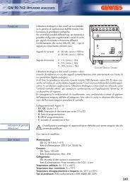
FUNZIONE<br />
• La stazione meteorologica EIB ha la funzione di raccogliere e di instradare i<br />
dati e gli eventi.<br />
E’ possibile collegare fino a quattro trasduttori (sensori) analogici, nonché un<br />
sensore combinato digitale.<br />
• La stazione meteorologica può analizzare sia segnali in tensione che<br />
segnali in corrente:<br />
Segnali in corrente 0...20 mA 4...20 mA<br />
Segnali in tensione 0...1 V 0..10 V<br />
• Gli ingressi in corrente vengono controllati per eventuali rotture del cavo.<br />
MONTAGGIO<br />
ATTENZIONE<br />
Non è consentito utilizzare altre tipologie di collegamento diverse da<br />
quelle approvate da <strong>Gewiss</strong>; ciò potrebbe influenzare negativamente<br />
la sicurezza e la funzionalità del sistema.<br />
Agganciare il dispositivo alla guida profilata da 35 x 7,5 mm (DIN EN<br />
50022). Per il funzionamento la stazione meteorologica EIB richiede<br />
una alimentazione esterna da 24 V, per esempio tramite<br />
l’alimentatore GW 90 780.<br />
Esso può alimentare anche i sensori collegati, il loro riscaldamento<br />
oppure un modulo di ingresso analogico.<br />
Prima di attivare la tensione inserire il morsetto di collegamento per il<br />
sensore combinato - anche se non collegate nessun sensore<br />
combinato.<br />
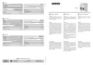
(C)<br />
Alimentatore<br />
GW 90 780<br />
Connettore bus<br />
6 poli<br />
Sensore<br />
combinato<br />
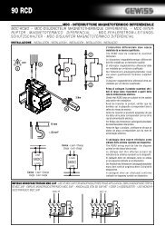
Figura 1<br />
ATTENZIONE<br />
Il morsetto di collegamento per l’attacco del sensore combinato deve<br />
essere inserito prima di attivare la tensione di rete in modo che<br />
l’ingresso digitale non entri per errore in contatto con linee sotto<br />
tensione!<br />
Questo potrebbe pregiudicare la sicurezza dell’intero sistema!<br />
L’apparecchio e i sensori o i moduli di ampliamento (ingresso<br />
analogico) collegati potrebbero andare distrutti!<br />
PER LA VOSTRA SICUREZZA<br />
ATTENZIONE<br />
Gli apparecchi elettrici possono essere installati e montati solo da<br />
elettricisti specializzati. Osservare le disposizioni antinfortunistiche in<br />
vigore. L’inosservanza delle istruzioni di installazione può provocare<br />
incendi o altri pericoli.<br />
Non è consentito utilizzare altre tipologie di collegamento diverse da<br />
quelle indicate da <strong>Gewiss</strong>; ciò potrebbe influenzare negativamente la<br />
sicurezza e la funzionalità del sistema.<br />
ATTENZIONE<br />
Il morsetto di collegamento per il sensore combinato deve essere<br />
inserito prima di attivare la tensione di rete, in modo che l’ingresso<br />
digitale non entri per errore in contatto con linee sotto tensione!<br />
Questo potrebbe pregiudicare la sicurezza dell’intero sistema!<br />
L’apparecchio e i sensori o i moduli di ampliamento (ingresso<br />
analogico) collegati potrebbero andare distrutti!<br />
INFORMAZIONI SUL SISTEMA<br />
Questo apparecchio è un prodotto del sistema EIB/KNX ed è conforme alle<br />
direttive KNX.<br />
Una conoscenza tecnica dettagliata acquisita tramite formazione specifica<br />
costituisce un prerequisito per comprendere il sistema.<br />
Le funzioni dell'apparecchio dipendono dal software.<br />
Per informazioni dettagliate su quale software deve essere caricato e sul<br />
relativo ambito delle funzioni, vi preghiamo di consultare la banca dati<br />
prodotti del produttore.<br />
La progettazione, l’installazione e la messa in funzione dell’apparecchio<br />
vengono effettuate con l’ausilio di un software certificato KNX.<br />
La banca dati prodotti e le descrizioni tecniche sempre aggiornate sono<br />
disponibili in Internet all'indirizzo www.gewiss.com.<br />
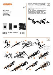
COLLEGAMENTO, CONTROLLI (Figura 1)<br />
+Us:<br />
Alimentazione dei trasduttori esterni<br />
GND:<br />
Potenziale di riferimento per +Us e ingressi Ch1...Ch4<br />
Ch1...Ch4: Ingressi per i trasduttori (sensori)<br />
EIB:<br />
Morsetto EIB<br />
24 V AC/DC: Alimentazione esterna<br />
Sensore combinato: Morsetto quadripolare per sensore combinato (vento,<br />
pioggia, luminosità, crepuscolare)<br />
Bus di sistema Connettore a 6 poli per il collegamento di un modulo<br />
di ingresso analogico aggiuntivo<br />
(A):<br />
Tasto di programmazione<br />
(B):<br />
LED di programmazione<br />
(C):<br />
LED di stato a tre colori (rosso, arancione, verde)<br />
(D):<br />
Trasduttore (sensore)<br />
ALIMENTAZIONE DEI SENSORI COLLEGATI<br />
• I sensori collegati possono essere alimentati tramite i morsetti +US e<br />
GND della stazione meteorologica (vedi figura 1)<br />
• L’assorbimento di corrente complessivo di tutti i sensori alimentati non<br />
può superare 100 mA.<br />
• I morsetti +US e GND sono disponibili doppi e sono collegati<br />
internamente l’uno con l’altro.<br />
• In caso di cortocircuito tra i morsetti +US e GND la tensione viene<br />
disinserita.<br />
• I sensori collegati possono essere alimentati anche esternamente (per<br />
es. se il relativo assorbimento di corrente supera 100 mA). Il<br />
collegamento agli ingressi dei sensori viene effettuato poi tra i morsetti<br />
Ch1…Ch4 e GND.
SENSORI COLLEGABILI<br />
Utilizzando i sensori indicati di seguito il software fornisce dei valori<br />
preimpostati. Se si utilizzano altri sensori, i parametri da impostare devono<br />
essere determinati in precedenza.<br />
Tipo Utilizzo Art. N.<br />
Luminosità Esterno GW 90 772<br />
Crepuscolare Esterno GW 90 773<br />
Temperatura Esterno GW 90 775<br />
Vento Esterno GW 90 771<br />
Pioggia Esterno GW 90 774<br />
LED DI STATO<br />
Spento:<br />
Nessuna alimentazione<br />
Arancione / acceso:<br />
Scansione del modulo da parte della<br />
stazione meteorologica<br />
Arancione / lampeggia lentamente: Scansione del sensore combinato<br />
(attesa di assegnazione di un sensore<br />
combinato)<br />
Arancione / lampeggia rapidamente: Scansione del modulo di ampliamento<br />
Rosso / acceso:<br />
Errore: nessuna configurazione<br />
Rosso / lampeggia lentamente: Errore: tensione insufficiente sul bus di<br />
estensione (in caso di collegamento di<br />
ingresso analogico aggiuntivo)<br />
Rosso / lampeggia rapidamente: Errore: errore nei parametri<br />
Verde / lampeggia lentamente: Assegnazione degli indirizzi, scansione<br />
del modulo conclusa, configurazione OK<br />
LED verde / lampeggia rapidamente: Download dei parametri nei moduli<br />
LED verde / acceso:<br />
scansione del modulo completata, tutto OK<br />
Lampeggio lento = 1/s, lampeggio rapido = 2/s<br />
DATI TECNICI<br />
Alimentazione<br />
- Tensione di alimentazione: 24 V AC ±10 %,<br />
24 V DC +25% / -10%<br />
- Corrente assorbita: max. 250 mA<br />
- Tensione EIB: 24 V DC (+6 V / -4 V)<br />
- Potenza assorbita EIB: tip. 150 mW<br />
Temperatura ambiente: da -5 °C fino a +45 °C :<br />
Temperatura di deposito/trasporto: da -25 °C fino a +70 °C<br />
Umidità Ambiente/deposito/trasporto: max. 93% di umidità relativa,<br />
nessuna condensa<br />
Tipo di protezione: IP 20 come da DIN EN 60529<br />
Larghezza di montaggio: 4 unità / 70 mm<br />
Peso: circa 150 g<br />
Connessione, Ingressi, Alimentazione<br />
Morsetti a vite<br />
- Conduttore singolo (rigido) da 0,5 mm 2 fino a 4 mm 2<br />
- Conduttore multifilare (flessibile) senza puntale: da 0,34 mm 2 fino a 4 mm 2<br />
- Conduttore multifilare (flessibile) con puntale: da 0,14 mm 2 fino a 2,5 mm 2<br />
- BUS EIB: morsetto di collegamento e di derivazione<br />
Sensore meteorologico combinato: morsetto quadripolare<br />
Modulo di ampliamento: spina a sei poli<br />
Ingressi sensore<br />
- Quantità: 4 analogici, 1 digitale<br />
- Segnali sensore analizzabili (analogici): 0 ... 1 V DC, 0 ... 10 V DC,<br />
0 ... 20 mA DC, 4 ... 20 mA DC<br />
- Impedenza misurazione della tensione: circa 18 kΩ<br />
- Impedenza misurazione della corrente: circa 100Ω<br />
- Alimentazione sensori esterni (+Us): 24 V DC. max, 100 mA DC<br />
- Collegamento moduli di ampliamento: 24 V DC, max. 80 mA<br />
Si riserva il diritto a modifiche tecniche.<br />
GEWISS - MATERIALE ELETTRICO<br />
SAT<br />
+39 035 946 111<br />
8.30 - 12.30 / 14.00 - 18.00<br />
da lunedì a venerdì<br />
+39 035 946 260<br />
24 ore al giorno<br />
SAT on line<br />
@ gewiss@gewiss.com<br />
Cod. 7.01.0.346.0
GB<br />
WEATHER STATION<br />
Article n.<br />
GW 90 779<br />
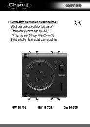
(D)<br />
(A)<br />
(B)<br />
(C)<br />
Power supply<br />
GW 90 780<br />
SAFETY WARNINGS<br />
ATTENTION<br />
Electrical equipment must be installed and fitted by qualified<br />
electricians only and in strict observance of the relevant accident<br />
prevention regulations.<br />
Failure to observe any of the installation instructions may result in<br />
fire and other hazards.<br />
The use of connecting cables other than those approved by <strong>Gewiss</strong> is<br />
not permitted and can have a negative effect on electrical safety and<br />
system functions.<br />
ATTENTION<br />
The terminal block for the connection of the combi-sensor must be<br />
plugged on before the mains voltage is switched on and during<br />
operation to prevent the digital input from unintentional contact with<br />
live wires.<br />
This would endanger the safety of the entire system. As a result, the<br />
device and any sensors connected or extension modules (analog<br />
input) may be irreparably damaged.<br />
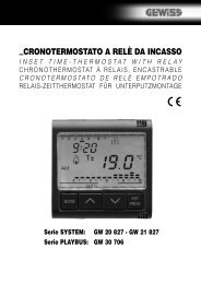
SYSTEM INFORMATION<br />
System<br />
Bus 6-pol,<br />
Combi<br />
sensor<br />
Figure 1<br />
This device is a product of the instabus-KNX/EIB system and complies<br />
with KNX directives. Detailed technical knowledge obtained in instabus<br />
training courses is a prerequisite to proper understanding.<br />
The functionality of this device depends upon the software.<br />
Detailed information on loadable software and attainable functionality as<br />
well as the software itself can be obtained from the manufacturer's<br />
product database.<br />
Planning, installation and commissioning of the unit is effected by means<br />
of KNX-certified software.<br />
An updated version of the product database and the technical<br />
descriptions are available in the Internet at www.gewiss.com.<br />
FUNCTION<br />
• The EIB weather station serves to collect and to transmit weather data<br />
and events. Up to four analog transducers as well as a digital combisensor<br />
can be connected.<br />
• The weather station can evaluate both voltage and current signals:<br />
Current signals 0...20 mA 4...20 mA<br />
Voltage signals 0...1 V 0...10 V<br />
• The current inputs are monitored for wire breakage.<br />
INSTALLATION<br />
SAFETY WARNINGS<br />
The use of connecting cables other than those approved by <strong>Gewiss</strong><br />
ist not permitted and can have a negative effect on electrical safety<br />
and system functions. Snap the device onto a 35 x 7.5 top hat rail as<br />
per DIN EN 50022. For operation, the EIB weather station needs an<br />
external 24 V source such as the power supply, AC 24 V/1 A, part no.<br />
GW 90 780. The latter can also supply the sensors connected, or<br />
their heating or an analogue input module.<br />
Prior to switching on the voltage, plug on the terminal block for the<br />
connection of a combi-sensor, even if no such sensor is used.<br />
SAFETY WARNINGS<br />
The terminal block for the connection of the combi-sensor must be<br />
plugged on before the mains voltage is switched on and during<br />
operation to prevent the digital input from unintentional contact with<br />
live wires. This would endanger the safety of the entire system.<br />
As a result, the device and any sensors connected or extension<br />
modules (analog input) may be irreparably damaged.<br />
CONNECTION, CONTROLS (fig. 1)<br />
+Us:<br />
power supply of external transducers<br />
GND:<br />
ref. potential for +Us and inputs K1...K4<br />
Ch1 ... Ch4: measured-value inputs<br />
EIB:<br />
EIB connecting terminal<br />
24 V AC/DC: external power supply voltage<br />
4-pole combi-sensor: connecting terminal, 4-pole, for combisensor<br />
(wind, rain, brightness, twilight)<br />
6-pole system bus: system connector, 6-pole, for the connection of an<br />
analog input extension module<br />
(A):<br />
programming key<br />
(B):<br />
programming LED<br />
(C):<br />
status LED, three-colour (red, orange, green)<br />
(D):<br />
transducer<br />
POWER SUPPLY OF SENSORS CONNECTED<br />
• All sensors connected can be supplied via terminals +US and GND of the<br />
weather station (refer to Figura 1).<br />
• The total current consumption of all sensors supplied this way must not<br />
exceed 100 mA.<br />
• Terminals +US and GND are provided in duplicate and are internally<br />
interconnected.<br />
• In the event of a short-circuit between +US and GND, the voltage will be<br />
switched off.<br />
• Sensors connected can also be supplied externally (e. g. if their current<br />
consumption exceeds 100 mA). In such case, connection to the sensor<br />
inputs must be made between terminals Ch1...Ch4 and GND.<br />
SENSORS SUITABLE FOR CONNECTION<br />
For any of the following transducers, the software provides preset values. If other<br />
sensors are used, the parameters to be set must be determined beforehand.<br />
Type Use Part no.<br />
Brightness outdoor GW 90 772<br />
Twilight outdoor GW 90 773<br />
Temperature outdoor GW 90 775<br />
Wind outdoor GW 90 771<br />
Rain outdoor GW 90 774
STATUS LED<br />
OFF:<br />
no power supply<br />
Orange/ON:<br />
weather station scanning modules<br />
Orange/slowly blinking: combi-sensor module scan (waiting for assignment<br />
of a combi-sensor)<br />
Orange/quickly blinking: series mounting unit (REG) extension module<br />
scan<br />
Red/ON: error: no configuration in controller<br />
Red/slowly blinking: error: undervoltage on extension bus<br />
Red/quickly blinking: error: wrong parameterization<br />
Green/slowly blinking: address assignment, module scan completed,<br />
configuration OK<br />
Green/quickly blinking: parameter download into modules<br />
Green/ON:<br />
module scan completed, everything OK<br />
Slowly blinking = 1/s; quickly blinking = 2/s<br />
TECHNICAL DATA<br />
Power supply<br />
- Supply voltage: 24 VAC ± 10 %,<br />
24 VDC +25 % / -10 %<br />
- Current consumption: 250 mA max.<br />
- EIB voltage: 24 VDC (+6 V / -4 V)<br />
- EIB power consumption: 150 mW typ.<br />
Ambient temperature: -5 °C to +45 °C<br />
Storage/transport temperature: -25 °C to +70 °C<br />
Humidity Ambient/storage/transport: 93 % RH max., no condensation<br />
Protective system: IP 20 as per DIN EN 60529<br />
Installation width: 4 pitch / 70 mm<br />
Weight: approx. 150 g<br />
Connections Inputs, power supply<br />
screw terminals:<br />
- single-wire 0.5 mm 2 to 4 mm 2<br />
- stranded wire (without ferrule) 0.34 mm 2 to 4 mm 2<br />
- stranded wire (with ferrule) 0.14 mm 2 to 2.5 mm 2<br />
- instabus EIB: connecting and branch terminal<br />
Combi-sensor: 4-pole connecting terminal<br />
Extension module: 6-pole system connector<br />
Sensor inputs<br />
- Number: 4x analog, 1x digital<br />
- Evaluable sensor (signals analog): 0 .. 1 V DC, 0 .. 10 V DC,<br />
0 .. 20mA DC, 4 .. 20mA DC<br />
- Voltage measurement impedance: approx. 18 kΩ<br />
- Current measurement impedance: approx. 100 Ω<br />
- External sensor power supply (+Us): 24 VDC, 100 mA max.<br />
- Extension module connection: 24 VDC, 80 mA max.<br />
Subject to technical modifications.<br />
GEWISS - MATERIALE ELETTRICO<br />
SAT<br />
+39 035 946 111<br />
8.30 - 12.30 / 14.00 - 18.00<br />
for monday to friday<br />
+39 035 946 260<br />
24 hours/day<br />
SAT on line<br />
@ gewiss@gewiss.com<br />
Cod. 7.01.0.346.0