Create successful ePaper yourself
Turn your PDF publications into a flip-book with our unique Google optimized e-Paper software.
<strong>VM</strong>/100M32<br />
<strong>VM</strong>/106M32<br />
<strong>VM</strong>/112M32<br />
<strong>BPT</strong> SpA<br />
30020 Cinto Caomaggiore<br />
Venezia - Italy<br />
LED 1<br />
LED 2<br />
LED 3<br />
D<br />
A<br />
LED 4<br />
I<br />
ISTRUZIONI PER<br />
L’INSTALLAZIONE<br />
Sulla parte inferiore dello schermo compare una<br />
riga di dati che riporta le seguenti indicazioni:<br />
AVVERTENZE<br />
PER L’INSTALLATORE<br />
Queste <strong>istr</strong>uzioni devono essere allegate al<br />
derivato interno.<br />
MONITOR CON MEMORIA<br />
D’IMMAGINI <strong>VM</strong>/100M32<br />
Questo monitor permette di memorizzare fino a<br />
32 immagini.<br />
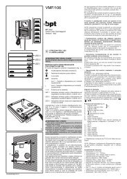
E’ munito dei seguenti comandi e segnalazioni<br />
(fig. 1):<br />
✱ 02 18:32 NOV 30 93<br />
minuti<br />
cursore<br />
mese<br />
giorno<br />
anno<br />
C<br />
04.2001/2402-6822<br />
24h 1<br />
STAND<br />
BY<br />
ON<br />
OFF 1 2 3 4<br />
STAND<br />
BY<br />
60” 2÷30<br />
S<br />
1<br />
2<br />
Acceso/spento-luminosità (comando<br />
laterale D, fig. 1).<br />
Inserimento-selezione posto esterno.<br />
Luce scale.<br />
Apriporta.<br />
• Aux 1 - Pulsante a disposizione per<br />
comandi supplementari.<br />
•<br />
Aux 2 - Pulsante a disposizione per<br />
comandi supplementari.<br />
LED 1 Indicatore luminoso verde a disposizione<br />
per segnalazioni ausiliarie (allarmi,<br />
controlli, ecc.).<br />
LED 2 Indicatore luminoso giallo a disposizione<br />
per segnalazioni ausiliarie (allarmi,<br />
controlli, ecc.).<br />
LED 3 Indicatore luminoso rosso a disposizione<br />
per segnalazioni ausiliarie (allarmi,<br />
controlli, ecc.).<br />
Il LED 3 non è utilizzabile con il monitor<br />
nella versione da tavolo (<strong>VM</strong>/100<br />
M32 + VKT/100).<br />
Pulsante per la selezione dell’ora e<br />
della data.<br />
Pulsante di avanzamento per l’impostazione<br />
dell’ora e della data.<br />
Pulsante per la memorizzazione delle<br />
immagini in modo automatico (LED<br />
verde 4 acceso).<br />
Pulsante per la visualizzazione delle<br />
immagini memorizzate.<br />
Pulsante per la cancellazione delle<br />
immagini memorizzate.<br />
Pulsante per la memorizzazione<br />
manuale delle immagini.<br />
LED 4 Indicatore luminoso verde per la segnalazione<br />
di reg<strong>istr</strong>azione automatica delle<br />
immagini con la chiamata dal posto<br />
esterno.<br />
Simbolo dello stato in cui deve trovarsi<br />
il LED 4 verde ( = acceso, = spento)<br />
per ottenere le funzioni indicate sul<br />
pulsante relativo.<br />
ore<br />
numero delle immagini memorizzate<br />
quando compare il simbolo ✱ l’immagine visualizzata<br />
sullo schermo è quella dal vivo, se compare<br />
il simbolo l’immagine visualizzata è<br />
quella memorizzata.<br />
I pulsanti Aux 1 e Aux 2 chiudono rispettivamente<br />
i morsetti 11 e 12 verso il negativo (−) dell’alimentazione<br />
(24V 100mA max.).<br />
I LED 1, 2 e 3 vengono attivati collegando i<br />
rispettivi morsetti 13, 14 e 15 al negativo (−) dell’alimentazione<br />
(morsetto 5) tramite un dispositivo<br />
del servizio controllato.<br />
Il fusibile di protezione F1 tipo T 630mA,<br />
situato sul circuito stampato del supporto<br />
(fig. 3-5), deve essere sostituito con il fusibile<br />
F1 tipo T 1A fornito con il monitor.<br />
(Fusibile: F = rapido, T = ritardato).<br />
AVVERTENZE PER L’UTENTE<br />
- Non aprire o manomettere l’apparecchio;<br />
all’interno é presente alta tensione.<br />
- Evitare urti o colpi all’apparecchio che potrebbero<br />
provocare la rottura del cinescopio con<br />
conseguente proiezione di frammenti di vetro.<br />
- In caso di guasto, modifica o intervento sugli<br />
apparecchi dell’impianto (alimentatore, ecc.)<br />
avvalersi di personale specializzato.<br />
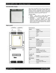
Il monitor è predisposto anche per operare in<br />
quattro modi speciali che possono essere selezionati<br />
mediante i dip-switch C di fig. 2 come<br />
segue:<br />
• Funzionamento in stand-by.<br />
Normalmente escluso (dip-switch 1 in posizione<br />
OFF, tempo di accensione 4 sec.) il funzionamento<br />
in stand-by può essere attivato portando<br />
lo stesso dip-switch in posizione ON (tempo di<br />
accensione 2 sec.).<br />
• Funzionamento continuo (da utilizzare<br />
esclusivamente per funzioni di videocontrollo<br />
in impianti monofamiliari con telecamera,<br />
costantemente alimentata, separata dal<br />
posto esterno).<br />
1
C<br />
B<br />
Il monitor viene fornito con il dip-switch 2 in<br />
posizione OFF.<br />
Per ottenere questo tipo di funzionamento è<br />
necessario portare il dip-switch in posizione ON<br />
e togliere il ponticello S (fig. 2).<br />
Lo spegnimento del monitor viene effettuato<br />
mediante l’interruttore laterale D di fig. 1.<br />
• Accensione contemporanea di più monitor<br />
in parallelo mediante unica chiamata.<br />
Per ottenere questo tipo di funzionamento da un<br />
gruppo di monitor collegati alla stessa chiamata<br />
è necessario:<br />
a) assicurarsi che su uno solo dei monitor il dipswitch<br />
3 sia in posizione ON;<br />
b) portare in posizione OFF il dip-switch 3 dei<br />
rimanenti monitor.<br />
• Spegnimento del monitor mediante il<br />
comando apriporta.<br />
a) Impianti con alimentatore VA/100.<br />
Il monitor si spegne normalmente a fine temporizzazione<br />
(dip-switch 4 in posizione OFF).<br />
Portando lo stesso dip-switch in posizione ON il<br />
monitor verrà spento mediante l’azionamento<br />
del comando apriporta.<br />
b)Impianti con alimentatore VA/100.01.<br />
Il dip-switch 4 deve essere in posizione OFF.<br />
Lo spegnimento del monitor è selezionato tramite<br />
il dip-switch 2 dell’alimentatore VA/100.01.<br />
Ad ogni interruzione dell’alimentazione principale<br />
l’impostazione dell’ora, della data e le<br />
immagini memorizzate vengono cancellate.<br />
Per evitare questo fenomeno prevedere nell’impianto<br />
un’alimentazione di soccorso.<br />
4 - Visualizzazione delle immagini memorizzate.<br />
Spegnere il LED 4 verde premendo il pulsante<br />
.<br />
Accendere il monitor agendo sul pulsante<br />
e premere il pulsante per la visualizzazione<br />
delle immagini.<br />
La riga dei dati sullo schermo indica il numero<br />
progressivo dell’immagine, l’ora e la data in cui<br />
è stata effettuata la memorizzazione.<br />
2<br />
3<br />
3<br />
F1<br />
3<br />
1<br />
2 4<br />
F1<br />
5<br />
1<br />
E<br />
2<br />
6<br />
Segnale di chiamata<br />
Il volume della nota di chiamata dal posto esterno<br />
è regolabile mediante il potenziometro<br />
accessibile dal foro laterale A (fig. 1).<br />
In caso di impianti con chiamata temporizzata<br />
(alimentatore mod. VA/100.01) l’interruzione<br />
della chiamata stessa si verifica alla fine del<br />
tempo programmato, o sollevando la cornetta o<br />
premendo uno qualsiasi dei pulsanti<br />
.<br />
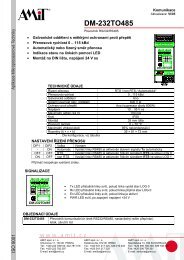
Chiamata dal pianerottolo<br />
Qualora l’impianto preveda la chiamata dal pianerottolo,<br />
inserire il ronzatore ER/12 nell’apposita<br />
sede del supporto (fig. 12) ed effettuare i collegamenti<br />
come indicato nello schema di fig.<br />
13.<br />
ISTRUZIONI PER L’USO DEL DISPOSITIVO<br />
DI MEMORIZZAZIONE<br />
1 - Impostazione dell’ora e della data.<br />
Spegnere il LED 4 verde premendo il pulsante<br />
, accendere il monitor premendo il pulsante<br />
. Agire sul pulsante per selezionare<br />
in successione ora, minuti, mese, giorno ed<br />
anno: sopra il dato selezionato compare il cursore<br />
lampeggiante --.<br />
Premere il pulsante per raggiungere il valore<br />
desiderato.<br />
Per il funzionamento dell’apparecchio è<br />
necessario che la procedura d’impostazione<br />
venga conclusa (il cursore scompare dallo<br />
schermo premendo il pulsante dopo la<br />
selezione dell’anno).<br />
2 - Memorizzazione automatica.<br />
Premere il pulsante assicurandosi che il<br />
LED 4 verde sia acceso.<br />
Ad ogni chiamata dal posto esterno, o autoinserimento<br />
dal monitor (pulsante ) l’immagine<br />
ripresa dalla telecamera viene memorizzata<br />
automaticamente.<br />
3 - Memorizzazione manuale.<br />
Escludere la memorizzazione automatica premendo<br />
il pulsante (il LED 4 verde deve spegnersi).<br />
Accendere il monitor premendo il pulsante di<br />
inserimento-selezione posto esterno , e<br />
quindi premere il pulsante di memorizzazione<br />
manuale (il simbolo che compare momentaneamente<br />
sullo schermo all’inizio della riga<br />
dei dati, indica l’avvenuta reg<strong>istr</strong>azione).<br />
IMPORTANTE. La capacità della memoria è di<br />
32 immagini; ogni successiva immagine memorizzata<br />
cancella in sequenza le immagini precedentemente<br />
reg<strong>istr</strong>ate.<br />
5 - Cancellazione delle immagini memorizzate.<br />
Spegnere il LED 4 verde premendo il pulsante<br />
.<br />
Accendere il monitor agendo sul pulsante e<br />
premere il pulsante per più di 3 secondi (la<br />
cifra che indica la quantità di immagini memorizzate<br />
si azzera confermando l’avvenuta operazione).<br />
IMPORTANTE. L’impostazione dell’ora e della<br />
data, la memorizzazione manuale e la cancellazione<br />
delle immagini memorizzate sono possibili<br />
solamente con il LED 4 verde spento e con<br />
l’immagine dal vivo presente sullo schermo (all’inizio<br />
della riga dei dati deve essere presente il<br />
simbolo ✱).<br />
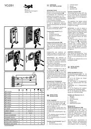
MONITOR INTERCOMUNICANTE CON<br />
MEMORIA D’IMMAGINI <strong>VM</strong>/106M32<br />
Oltre ai comandi e segnalazioni del mod.<br />
<strong>VM</strong>/100M32, è munito di 6 pulsanti di chiamata<br />
e l’indicatore luminoso rosso (LED 3) è utilizzabile<br />
per la segnalazione di linea occupata (fig.<br />
9).<br />
Questo apparecchio consente la realizzazione<br />
di sistemi intercomunicanti fino ad un massimo<br />
di 6 unità. Tali sistemi sono compatibili con normali<br />
sistemi videocitofonici della serie 100, di<br />
cui rappresentano un possibile ampliamento di<br />
funzioni.<br />
Il collegamento in parallelo tra gli intercomunicanti<br />
mediante quattro conduttori, con sezione<br />
minima di 0,28 mm 2 (Ø 0,6 mm), oltre al normale<br />
collegamento videocitofonico permette la<br />
chiamata (di tonalità diversa da quella proveniente<br />
dal posto esterno), il segreto di conversazione<br />
ed il collegamento audio indipendente<br />
dal resto dell’impianto.<br />
Ogni apparecchio può chiamare o essere chiamato<br />
da qualsiasi altro monitor intercomunicante<br />
collegato.<br />
Durante una comunicazione interna l’indicatore<br />
luminoso rosso (LED 3) segnala che la linea è<br />
impegnata.<br />
La linea viene occupata da chi chiama all’atto<br />
della chiamata stessa e viene liberata solo<br />
quando chi l’ha effettuata ripone la cornetta.<br />
Dal momento che il collegamento intercomunicante<br />
è indipendente da quello videocitofonico<br />
è possibile continuare una comunicazione interna<br />
anche in caso di chiamata dal posto esterno<br />
a cui si risponda da un terzo monitor.<br />
Ad ogni apparecchio deve essere assegnato<br />
un numero d’identificazione; tale è il numero<br />
con cui gli altri intercomunicanti potranno chiamarlo<br />
(pulsanti dal n. 1 al n. 6 di fig. 9).<br />
Per assegnare tale numero portare in posizione<br />
ON l’interruttore corrispondente B di fig. 10 (accessibile<br />
dal retro del monitor) lasciando tutti gli<br />
altri in posizione OFF.<br />
Il monitor è predisposto anche per operare in<br />
quattro modi speciali che possono essere selezionati<br />
mediante i dip-switch C di fig. 10 come<br />
indicato per il mod. <strong>VM</strong>/100M32.<br />
MONITOR INTERCOMUNICANTE<br />
CON MEMORIA D’IMMAGINI <strong>VM</strong>/112M32<br />
Di disegno e caratteristiche simili al mod.<br />
<strong>VM</strong>/106M32 consente la realizzazione di
4<br />
D<br />
LED 4<br />
6<br />
LED 1<br />
LED 2<br />
LED 3<br />
F<br />
5<br />
6<br />
A<br />
1<br />
2<br />
3<br />
4<br />
5<br />
6<br />
7<br />
8<br />
9<br />
impianti intercomunicanti fino a 12 unità.<br />
Il pulsante • viene utilizzato per la funzione di<br />
raddoppio delle chiamate ed il LED 1 verde per<br />
la segnalazione di raddoppio inserito.<br />
Il pulsante Aux 2 chiude il morsetto 12 verso il<br />
negativo (−) dell’alimentazione (24V 100mA<br />
max.).<br />
Il LED 2 viene attivato collegando il morsetto 14<br />
al negativo (−) dell’alimentazione (morsetto 5)<br />
tramite un dispositivo del servizio controllato.<br />
Numero d’identificazione<br />
Ad ogni apparecchio deve essere assegnato<br />
un numero d’identificazione; tale è il numero<br />
con cui gli altri intercomunicanti potranno chiamarlo<br />
(pulsanti dal n. 1 al n. 6 di fig. 9).<br />
Per assegnare tale numero è necessario agire<br />
come segue:<br />
Fino al 6° apparecchio collegato (chiamata normale):<br />
- Individuare tra gli interruttori B all’interno dell’apparecchio<br />
(fig. 11) quello con il numero<br />
desiderato e portarlo in posizione ON.<br />
- Eliminare il ponticello R (fig. 11).<br />
Dal 7° al 12° apparecchio collegato (chiamata<br />
con raddoppio):<br />
Procedere come indicato nel precedente paragrafo<br />
assicurandosi che il ponticello R sia inserito.<br />
Chiamate<br />
Per effettuare le chiamate agli apparecchi dal n.<br />
1 al n. 6, premere il pulsante corrispondente dal<br />
n. 1 al n. 6 (fig. 9).<br />
Per effettuare le chiamate agli apparecchi dal n.<br />
7 al n. 12 è necessario agire come segue:<br />
- Premere il pulsante di raddoppio • di fig. 9<br />
(l’indicatore luminoso LED 1 segnala l’attivazione<br />
della funzione).<br />
- Premere il pulsante corrispondente all’apparecchio<br />
che si desidera chiamare (1=7, 2=8,<br />
3=9, ... 6=12).<br />
Quando viene riposta la cornetta contemporaneamente<br />
si ripristina la funzione di chiamata<br />
normale e si spegne anche l’indicatore luminoso<br />
per la segnalazione di raddoppio inserito.<br />
Il monitor è predisposto anche per operare in<br />
quattro modi speciali che possono essere selezionati<br />
mediante i dip-switch C di fig. 11 come<br />
indicato per il mod. <strong>VM</strong>/100M32.<br />
Funzione dei morsetti<br />
<strong>VM</strong>/100M32 e <strong>VM</strong>/106M32<br />
da 1 a 15: morsetti per il collegamento al kit<br />
VKP/100 con monitor <strong>VM</strong>/100M32.<br />
da 1 a 14: morsetti per il collegamento al kit<br />
VKT/100 con monitor <strong>VM</strong>/100M32.<br />
da 1 a 18: morsetti per il collegamento al kit<br />
VKP/100 o VKT/124 con monitor intercomunicante<br />
<strong>VM</strong>/106M32.<br />
1 segnale video<br />
( 1 )<br />
2 schermo segnale video<br />
3 segnale video<br />
4 schermo segnale video<br />
5 – 14 ÷ 17,5V<br />
6 + alimentazione monitor<br />
7 chiamata<br />
8 audio al monitor<br />
9 audio al posto esterno<br />
10 uscita +11,5V (50mA max.)<br />
11 Aux 1<br />
12 Aux 2<br />
13 LED 1 (verde)<br />
14 LED 2 (giallo)<br />
15 LED 3 (rosso)<br />
16 audio intercom.<br />
17 audio intercom.<br />
18 codice chiamata intercom.<br />
( 1 ) Resistenza di chiusura da 75Ω se la linea<br />
non prosegue.<br />
Funzione dei morsetti <strong>VM</strong>/112M32<br />
(morsetti per il collegamento al kit VKP/100 o<br />
VKT/124)<br />
1 segnale video<br />
( 1 )<br />
2 schermo segnale video<br />
3 segnale video<br />
4 schermo segnale video<br />
5 – 14 ÷ 17,5V<br />
6 + alimentazione monitor<br />
7 chiamata<br />
8 audio al monitor<br />
9 audio al posto esterno<br />
10 uscita +11,5V (50mA max.)<br />
11<br />
12 Aux 2<br />
13 LED 1 (verde)<br />
14 LED 2 (giallo)<br />
15 LED 3 (rosso)<br />
16 audio intercom.<br />
17 audio intercom.<br />
18 codice chiamata intercom.<br />
( 1 ) Resistenza di chiusura da 75Ω se la linea<br />
non prosegue.<br />
Caratteristiche tecniche<br />
<strong>VM</strong>/100M32 -<strong>VM</strong>/106M32<br />
• Cinescopio: 5” (12,5 cm) a 90°.<br />
• Standard CCIR.<br />
• Alimentazione: 14 ÷ 17,5Vcc.<br />
• Assorbimento: max. 830mA (190mA in standby,<br />
135mA a riposo).<br />
• Assorbimento per ogni LED: 7mA.<br />
• Banda passante a -3dB: 6MHz con immagine<br />
diretta, 4MHz con immagine memorizzata.<br />
• Ingresso video: 1Vpp (da 0,8 a 1,3Vpp).<br />
• Impedenza d’ingresso video: >30 kΩ.<br />
• Memoria video: 32 immagini.<br />
• Segnale di chiamata: bitonale con volume<br />
regolabile dal posto esterno; a nota continua<br />
per chiamate interne nella serie <strong>VM</strong>/106.<br />
• Aux 1 e Aux 2: contatti normalmente aperti<br />
verso il negativo (–) dell’alimentazione (24V<br />
100mA max.).<br />
• Temperatura di funzionamento: da 0 °C a +35 °C.<br />
• Dimensioni: 192 x 220 x 98 mm (profondità<br />
incasso 48 mm).<br />
Caratteristiche tecniche <strong>VM</strong>/112M32<br />
• Cinescopio: 5” (12,5 cm) a 90°.<br />
• Standard CCIR.<br />
• Alimentazione: 14 ÷ 17,5Vcc.<br />
• Assorbimento: max. 830mA (190mA in standby,<br />
135mA a riposo).<br />
• Assorbimento per ogni LED: 7mA.<br />
• Banda passante a -3dB: 6MHz con immagine<br />
diretta, 4MHz con immagine memorizzata.<br />
• Ingresso video: 1Vpp (da 0,8 a 1,3Vpp).<br />
• Impedenza d’ingresso video: >30 kΩ.<br />
• Memoria video: 32 immagini.<br />
• Segnale di chiamata: bitonale con volume<br />
regolabile dal posto esterno, a nota continua<br />
per chiamate interne.<br />
• Aux 2: contatto normalmente aperto verso il<br />
negativo (–) dell’alimentazione (24V 100mA<br />
max.).<br />
• Temperatura di funzionamento: da 0 °C a +35 °C.<br />
• Dimensioni: 192 x 220 x 98 mm (profondità<br />
incasso 48 mm).<br />
Fissaggio del monitor al supporto da parete<br />
Assicurarsi che il dispositivo di bloccaggio C<br />
sia spostato verso destra (posizione aperta<br />
fig. 3). Posizionare il monitor nel supporto da<br />
parete B, innestarlo al supporto stesso con<br />
movimento verso il basso e quindi bloccarlo in<br />
tale posizione mediante il dispositivo C.<br />
Nell’eseguire tali operazioni agire secondo l’ordine<br />
ed il senso indicati dalle frecce di fig. 4.<br />
Fissaggio del monitor al supporto da tavolo<br />
Inserire l’elemento E nell’apposita sede situata<br />
sul retro del monitor e bloccarlo con la vite corta<br />
in dotazione (fig. 6). Applicare il supporto da<br />
tavolo F agganciandolo prima dalla parte superiore<br />
(fig. 7) e bloccandolo poi al monitor con le<br />
due viti lunghe in dotazione (fig. 8).<br />
3
ON<br />
OFF<br />
B<br />
ON<br />
OFF<br />
B<br />
R<br />
4<br />
1 2 3 4 5 6<br />
1 2 3 4 5 6<br />
ON<br />
OFF 1 2 3 4<br />
C<br />
C<br />
24h 1<br />
STAND<br />
BY<br />
STAND<br />
BY<br />
60” 2÷30<br />
24h 1<br />
STAND<br />
BY<br />
S<br />
ON<br />
OFF 1 2 3 4<br />
STAND<br />
BY<br />
60” 2÷30<br />
S<br />
10<br />
11<br />
IMPORTANTE. Sostituire il fusibile situato<br />
sul supporto con quello fornito con il monitor<br />
(F1, T 1A).<br />
GB<br />
WARNING<br />
FOR THE INSTALLER<br />
These instructions should be attached to the<br />
receiver.<br />
<strong>VM</strong>/100M32 MONITOR<br />
WITH IMAGE STORAGE<br />
This monitor is able to store a maximum of 32<br />
images. It is equipped with the following controls<br />
and warnings, figure 1:<br />
Thumb-wheel D to switch the monitor<br />
ON/OFF and for the brightness control,<br />
figure 1.<br />
Button to bring the monitor live and<br />
manual sequencing of any additional<br />
panel/camera.<br />
Button to turn on stairs light.<br />
Door lock release button.<br />
• Aux 1 - Button for auxiliary services as<br />
required.<br />
•<br />
INSTALLATION<br />
INSTRUCTIONS<br />
Aux 2 - Button for auxiliary services as<br />
required.<br />
LED 1 Green LED can be used to indicate an<br />
external function.<br />
LED 2 Yellow LED can be used to indicate an<br />
external function.<br />
LED 3 Red LED can be used to indicate an<br />
external function.<br />
LED 3 cannot be utilised with the monitor<br />
in the table-top version (<strong>VM</strong>/100M32+<br />
VKT/100).<br />
Time/date select button.<br />
Time/date advance button.<br />
Image save button for automatic image<br />
storage (green LED 4 illuminated).<br />
Recorded image display button.<br />
Recorded image delete button.<br />
Manual image storage button.<br />
LED 4 Green LED, showing automatic image<br />
storage activated by a call from the<br />
entry panel.<br />
Symbol showing the status of green<br />
LED 4 ( = on, = off) required to<br />
access the functions indicated on the<br />
relevant command button.<br />
There is a data line at the bottom of the screen<br />
showing:<br />
✱ 02 18:32 NOV 30 93<br />
hours<br />
minutes<br />
cursor<br />
month<br />
day<br />
year<br />
number of images stored in the memory<br />
when the ✱ symbol appears, the monitor image<br />
is live.<br />
The symbol means that the image on the<br />
screen is recorded.<br />
Switches Aux 1 and Aux 2 are normally open,<br />
when actuated the contacts close on −0V DC.<br />
Max. current demand 100mA at 24V.<br />
To activate LED 1, 2 and 3 line 13 and 14<br />
respectively should be connected via an external<br />
switch device which is common to terminal 5<br />
of the system, 0V DC.<br />
Fuse F1, type T 630mA, located on support’s<br />
printed card, figure 3-5, must be substituted<br />
with fuse F1, type T 1A, supplied with the<br />
monitor.<br />
(Fuse: F = fast, T = slow).<br />
WARNINGS FOR THE USER<br />
- Please do not open or tamper the device (high<br />
voltage!).<br />
- Please avoid knocking or bumping the apparatus<br />
as it could result in the breakage of the picture<br />
tube and the consequent projection of glass<br />
fragments.<br />
- In the case of breakdown or modification of<br />
the apparatus of the system (such as power<br />
supplier …) please contact a specialized maintenance<br />
service.<br />
Four special monitor operation modes can be<br />
chosen by means of dip-switches C accessible<br />
from the rear of the monitor. Figure 2 shows<br />
position of dip-switches as supplied.<br />
• Stand-by mode.<br />
The dip-switch 1 is normally kept in the OFF<br />
position - the stand-by mode is not operating -<br />
the picture appears on the screen in 4 seconds<br />
approx.<br />
In the ON position it activates the stand-by, the<br />
picture appears on the screen almost instantaneously.<br />
• Monitor in constant mode.<br />
For use only in single house installations as<br />
close circuit television system with camera<br />
always powered and separated from entry<br />
panel. <strong>VM</strong>/100M32 is supplied from the factory<br />
with dip-switch 2 in the OFF position. To program<br />
the set the dip-switch 2 to ON position<br />
and remove jumper S, figure 2. The monitor can<br />
only be switched off by thumb-wheel switch D,<br />
figure 1.<br />
• Activation of more monitors by the same<br />
call.<br />
Dip-switch 3 is normally kept in the ON position,<br />
this way the call line loop is closed. If more<br />
monitors must be activated by the same call,<br />
leave only one with the dip-switch 3 in the ON<br />
position, all other monitors must have the dipswitch<br />
3 in the OFF position.<br />
Failure to have the dip-switches in the correct<br />
positions will result in the monitors not being<br />
activated.<br />
• Monitor/system turned off on door release.<br />
a) Systems with VA/100 main control unit.<br />
Dip-switch 4 is normally kept in the OFF position.<br />
In this position the monitor is turned off<br />
automatically by the system timer. Whit dip-switch<br />
4 in the ON position the monitor is turned off<br />
by pressing the door lock release button.<br />
b)Systems with VA/100.01 main control unit.<br />
Dip-switch 4 must be in the OFF position.<br />
Use dip-switch 2 of the VA/100.01 main control<br />
unit to turn off the monitor.<br />
Call tone<br />
It is possible to regulate the call tone level from<br />
the entry panel by adjusting the trimmer, accessible<br />
from the A hole placed on the right side of<br />
the monitor, figure 1.<br />
System using main control unit VA/100.01 has a<br />
timed call feature.<br />
The call stops either when the handset is lifted<br />
or when any<br />
button is pressed.<br />
Personal door-bell<br />
When the personal door-bell is required to be<br />
part of the video entry system, insert the ER/12
CP<br />
<strong>VM</strong>/…M32+<br />
VKP/100<br />
1<br />
2<br />
3<br />
4<br />
5<br />
6<br />
7<br />
8<br />
9<br />
10<br />
11<br />
ER/12<br />
C<br />
1<br />
2<br />
1B<br />
1A<br />
1<br />
2<br />
3<br />
4<br />
5<br />
6<br />
7<br />
8<br />
9<br />
10<br />
11<br />
12<br />
13<br />
14<br />
VA/100<br />
12<br />
13<br />
buzzer on the guides of VKP/100 wall mounting,<br />
figure 12, and connect the wires as shown in<br />
diagram of figure 13.<br />
USING THE IMAGE STORAGE SYSTEM<br />
1 - Set the current time and date.<br />
Switch off green LED 4 by pressing .<br />
Switch on the monitor by pressing the button.<br />
Use the button to set the time in hours<br />
and minutes followed by the month, day and<br />
year. The cursor -- will blink over the selected<br />
parameter.<br />
Press to get the required value.<br />
The unit will not work until the clock setting<br />
procedure is completed (the cursor disappears<br />
when the button is pressed after the<br />
year has been set).<br />
2 - Automatic image storage.<br />
Press and make sure that green LED 4 is<br />
illuminated. At each call from the entry panel or<br />
automatic monitor activation ( button), the<br />
camera image is automatically saved in the<br />
memory.<br />
3 - Manual image storage.<br />
You can deactivate the auto-save facility by<br />
pressing (green LED 4 should switch off).<br />
Switch on the monitor by pressing the entry<br />
panel insert-select button, and then press the<br />
manual save button (the symbol appear<br />
momentarily on the screen at the beginning of<br />
the data line to confirm the storage).<br />
IMPORTANT. Memory space is sufficient for 32<br />
images, each image over and above 32 will<br />
replace the images already stored in sequence.<br />
Each time the main power supplier is disconnected<br />
the clock and date setting will be lost<br />
along with the images in the memory. To avoid<br />
this risk install an emergency power supply.<br />
4 - Displaying recorded images from the<br />
memory.<br />
Switch off green LED 4 by pressing .<br />
Switch on the monitor by pressing the button<br />
marked and then press to display the<br />
images.<br />
The data line on the screen shows the progressive<br />
number of the images, and the time and<br />
date of storage.<br />
5 - Deleting images from the memory.<br />
Switch off green LED 4 by pressing . Switch<br />
on the monitor by pressing the button marked<br />
and then press and hold it down for<br />
more than 3 seconds (the figure indicating the<br />
number of stored images will return to zero confirming<br />
the operation).<br />
IMPORTANT. Setting the time and date, manual<br />
image storage and deletion of stored images<br />
are possible only when green LED 4 is off and<br />
with the live camera image displayed on the<br />
screen (the symbol ✱ must be present at the<br />
start of the data line).<br />
<strong>VM</strong>/106M32 INTERCOM MONITOR<br />
WITH IMAGE STORAGE<br />
<strong>VM</strong>/106M32 in addition to features of<br />
<strong>VM</strong>/100M32 is equipped with 6 intercom call<br />
buttons and the red light (LED 3) is used to indicate<br />
when the intercom audio line is engaged,<br />
figure 9.<br />
A maximum of 6 video intercom units can communicate<br />
to each other. The main features are:<br />
• Easy to install. The intercom units are connected<br />
in parallel to each other with 4 additional<br />
wires of 0.28 mm 2 (Ø 0.6 mm) cross-section.<br />
• Intercom call tone different from that of entry<br />
panel.<br />
• Audio privacy. Intercom and entry panel<br />
audio are separated. It is thus possible to continue<br />
an intercom conversation while answering<br />
from another monitor to an entry panel call.<br />
• All connected monitors can call each other.<br />
• The monitor intercom audio line will be occupied<br />
until the caller has replaced the handset.<br />
The red light LED indicates when the intercom<br />
audio line is engaged.<br />
• Installation with a mix of monitors with and<br />
without intercom facility is possible.<br />
• A call code - from 1 through 6 - can be given<br />
to each monitor matching the intercom call button<br />
number, by setting the corresponding dipswitch<br />
B to the ON position.<br />
Dip-switches B are accessible from the rear of<br />
the monitor, figure 10.<br />
Four special monitor operation modes can be<br />
chosen by means of dip-switches C, figure 10,<br />
accessible from the rear of the monitor as model<br />
<strong>VM</strong>/100M32.<br />
<strong>VM</strong>/112M32 INTERCOM MONITOR<br />
WITH IMAGE STORAGE<br />
Similar design and features to model<br />
<strong>VM</strong>/106M32, this model can be used to create<br />
intercom installations with up to 12 units.<br />
The • button is used to double the calls and<br />
green LED 1 illuminates to show that the double<br />
call function is enable.<br />
Switch Aux 2 is normally open, when actuated<br />
the contacts close on -0V DC. Max. current<br />
demand 100mA at 24V.<br />
To activate LED 2 line 14 should be connected<br />
via an external switch device which is common<br />
to terminal 5 of the system, 0V DC.<br />
Call code<br />
Procedure to set intercom calls 1÷6.<br />
- Slide the dip-switch B of required intercom<br />
call number to ON position, figure 11.<br />
- Remove link R.<br />
Procedure to set intercom code calls 7 ÷ 12.<br />
- Make sure link R is on place, figure 11.<br />
- Slide the dip-switch B of required intercom<br />
call number to ON position assuming nos. 1 ÷ 6<br />
correspond to 7 ÷ 12 respectively.<br />
Calls<br />
How to call receivers responding to codes 1 ÷ 6<br />
Pick-up handset and press the button 1 ÷ 6 corresponding<br />
to desired intercom number, figure<br />
9.<br />
How to call receivers responding to codes 7 ÷ 12<br />
- Pick-up handset and press • button, green<br />
LED is turned ON to indicate activation of 7 ÷ 12<br />
code calls, figure 9.<br />
- Press the button corresponding to desired<br />
intercom number assuming nos. 1 ÷ 6 correspond<br />
to 7 ÷ 12 respectively, figure 9.<br />
When replacing the handset on cradle the<br />
system switches back automatically to intercom<br />
code calls 1 ÷ 6 and green LED 1 is turned OFF.<br />
Four special monitor operation modes can be<br />
chosen by means of dip-switches C, figure 11,<br />
accessible from the rear of the monitor as model<br />
<strong>VM</strong>/100M32.<br />
Function of each terminal<br />
for <strong>VM</strong>/100M32 and <strong>VM</strong>/106M32<br />
from 1 to 15: terminals for connection to<br />
VKP/100 with monitor <strong>VM</strong>/100M32.<br />
from 1 to 14: terminals for connection to<br />
VKT/100 with monitor <strong>VM</strong>/100M32.<br />
from 1 to 18: terminals for connection to<br />
VKP/100 or VKT/124 with intercom monitor<br />
<strong>VM</strong>/106M32.<br />
1 video signal<br />
( 1 )<br />
2 video signal shield<br />
3 video signal<br />
4 video signal shield<br />
5 – 14 ÷ 17.5V<br />
6 + supply voltage to monitor<br />
7 call<br />
8 audio to monitor<br />
9 audio to entry panel<br />
10 +11.5V DC voltage output ( 2 )<br />
11 Aux 1<br />
12 Aux 2<br />
13 LED 1 (green)<br />
5
14 LED 2 (yellow)<br />
15 LED 3 (red)<br />
16 audio intercom.<br />
17 audio intercom.<br />
18 intercom call code<br />
( 1 )75Ω closing resistance if video line stops<br />
here.<br />
( 2 ) This voltage output is available for the time<br />
the monitor is operating.<br />
Max. current demand should not exceed 50mA.<br />
Function of each terminal <strong>VM</strong>/112M32 (terminals<br />
for connection to VKP/100 or VKT/124).<br />
1 video signal<br />
( 1 )<br />
2 video signal shield<br />
3 video signal<br />
4 video signal shield<br />
5 – 14 ÷ 17.5V<br />
6 + supply voltage to monitor<br />
7 call<br />
8 audio to monitor<br />
9 audio to entry panel<br />
10 +11.5V DC voltage output ( 2 )<br />
11<br />
12 Aux 2<br />
13 LED 1 (green)<br />
14 LED 2 (yellow)<br />
15 LED 3 (red)<br />
16 audio intercom.<br />
17 audio intercom.<br />
18 intercom call code<br />
( 1 )75Ω closing resistance if video line stops<br />
here.<br />
( 2 ) This voltage output is available for the time<br />
the monitor is operating. Max. current demand<br />
should not exceed 50mA.<br />
Technical features <strong>VM</strong>/100M32 and <strong>VM</strong>/106M32<br />
• Picture screen: 5” (12.5 cm) 90°.<br />
• CCIR standard.<br />
• Supply voltage: 14 ÷ 17.5V DC.<br />
• Max. current demand: 830mA (190mA in<br />
stand-by, 135mA quiescent).<br />
• Current demand per LED: 7mA.<br />
• Bandwidth response at -3dB: 6 MHz with live<br />
image, 4 MHz with recorded image.<br />
• Video input: 1Vpp (from 0.8Vpp to 1.3Vpp).<br />
• Video input impedance: >30 kΩ.<br />
• Store: 32 images.<br />
• Two-tone call signal with volume adjustment<br />
at entry panel; continuous tone call signal for<br />
internal calls for the <strong>VM</strong>/106M32.<br />
• Aux 1 and Aux 2: normally open switches,<br />
when actuated the contact closes to 0V DC.<br />
Current demand should not exceed 100mA at<br />
24V.<br />
• Working temperature range: from 0 °C to +35 °C.<br />
• Dimensions: 192 x 220 x 98 mm (recessed 48<br />
mm).<br />
Technical features <strong>VM</strong>/112M32<br />
• Picture screen: 5” (12.5 cm) 90°.<br />
• CCIR standard.<br />
• Supply voltage: 14 ÷ 17.5V DC.<br />
• Max. current demand: 830mA (190mA in<br />
stand-by, 135mA quiescent).<br />
• Current demand per LED: 7mA.<br />
• Bandwidth response at -3dB: 6 MHz with live<br />
image, 4 MHz with recorded image.<br />
• Video input: 1Vpp (from 0.8Vpp to 1.3Vpp).<br />
• Video input impedance: >30 kΩ.<br />
• Store: 32 images.<br />
• Two-tone call signal with volume adjustment<br />
at entry panel; continuous tone call signal for<br />
internal calls.<br />
• Aux 2: normally open switch, when actuated<br />
the contact closes to 0V DC. Current demand<br />
should not exceed 100mA at 24V.<br />
• Working temperature range: from 0 °C to +35 °C.<br />
• Dimensions: 192 x 220 x 98 mm (recessed 48<br />
mm).<br />
Fixing the monitor<br />
in the wall mounting<br />
Make sure the latch C is on the open position<br />
( ), i.e. pushed to the right hand-side, figure 3.<br />
6<br />
Insert the monitor into the wall mounting, push it<br />
downwards until the monitor card is firmly inserted<br />
into the terminal connector of the wall connecting<br />
frame.<br />
Slide the latch C to the left to block the monitor.<br />
Figure 4 shows the correct sequence to insert<br />
the monitor into the wall mounting.<br />
Fixing the monitor<br />
in the table-top mounting<br />
Insert the back frame E into the monitor recess<br />
and secure it with the provided short screw,<br />
figure 6. Attach the support F, inserting the top<br />
first, figure 7, and secure it with the two provided<br />
long screws, figure 8.<br />
IMPORTANT. Substitute the fuse located on<br />
the support’s printed card with the fuse supplied<br />
with the monitor (F1, T 1A).<br />
D<br />
ACHTUNG!<br />
NUR FÜR INSTALLATEUR<br />
Diese Anleitungen müßen jede der Sprechstelle<br />
begleiten.<br />
MONITOR MIT BILDSPEICHER<br />
<strong>VM</strong>/100M32<br />
Dieser Monitor kann bis 32 Bilder speichern. Mit<br />
folgenden Schalt- und Anzeigeelementen (Abb.<br />
1):<br />
EIN/AUS, Helligkeit (seitlich angeordnete<br />
Taste D, Abb. 1).<br />
Taste zur Bildein-und Kameraweiterschaltung<br />
von zusätzlichen Kamerastellen.<br />
Taste für Treppenlicht.<br />
Türöffnertaste.<br />
• Aux 1 - Taste für zusätzlich gewünschte<br />
Serviceschaltung.<br />
•<br />
LED 1 Grüne LED kann für die Anzeige einer<br />
externen Funktion verwendet werden.<br />
LED 2 Gelbe LED kann für die Anzeige einer<br />
externen Funktion verwendet werden.<br />
LED 3 Rote LED kann für die Anzeige einer<br />
externen Funktion verwendet werden.<br />
LED 3 ist mit dem Monitor in der<br />
Ausführung als Tischgerät nicht verwendbar<br />
(<strong>VM</strong>/100M32 + VKT/100).<br />
Taste für die Anwahl von Datum und<br />
Uhrzeit.<br />
Vorlauftaste für die Virgabe von Datum<br />
und Uhrzeit.<br />
Taste für die automatische Bildspeicherung<br />
(grüne LED 4 eingeschaltet).<br />
Taste für die Anzeige der gespeicherten<br />
Bilder.<br />
Taste für das Löschen der gespeicherten<br />
Bilder.<br />
Taste für die manuelle Bildspeicherung.<br />
LED 4 Grüne LED für die Anzeige der automatischen<br />
Bildspeicherung bei Anruf von<br />
der Außenstation.<br />
Symbol des Zustandes der grünen LED<br />
4 ( = eingeschaltet, = ausgeschaltet),<br />
um die auf der jeweiligen Taste<br />
gekennzeichneten Funktionen zu erhalten.<br />
INSTALLATIONS-<br />
ANLEITUNG<br />
Aux 2 - Taste für zusätzlich gewünschte<br />
Serviceschaltung.<br />
In der unteren Hälfte des Bildschirmes<br />
erscheint eine Datenzeile mit den folgenden<br />
Angaben:<br />
✱ 02 18:32 NOV 30 93<br />
Minuten<br />
Stunden<br />
Cursor<br />
Monat<br />
Tag<br />
Anzahl der gespeicherten Bilder<br />
Jahr<br />
Bei Anzeige des Symbols ✱ erscheint am<br />
Bildschirm das Direktübertragungsbild, bei<br />
Anzeige des Symbols erscheint das gespeicherte<br />
Bild.<br />
Die Tasten Aux 1 und Aux 2 (24V, 100mA max.)<br />
verbinden Klemme 11 bzw. 12 mit minus Pol des<br />
Netzgerätes.<br />
Um die LED 1, 2 und 3 zu aktivieren, sind deren,<br />
Anschlüsse, d.h. 13, 14 und 15 über das Gerät,<br />
dessen Funktion angezeigt werden soll (z.B.<br />
Relaise) mit dem Klemmanschluss 5 -0V DC zu<br />
verbinden.<br />
Die Sicherung F1 Typ T 630mA an der Platine<br />
des Rahmen (Abb. 3-5), ist durch die<br />
Sicherung F1 Typ T 1A zu ersetzen, die mit<br />
dem Monitor mitgeliefert wird.<br />
(Sicherung: F = flink, T = träge).<br />
HINWEISE FÜR DEN NUTZER<br />
- Bitte Gerät nicht öffnen oder aufbrechen<br />
(hohe Spannung!).<br />
- Zur Vermeidung eines Bildröhrenbruchs,<br />
Stösse und Schläge unterlassen.<br />
- Bei Störungen, Änderungen oder Reparaturen<br />
an den Geräten (Netzgerät, usw.) nur an<br />
Spezialisten wenden.<br />
Vier spezielle Funktionen können durch<br />
Kodierschalter C auf der Rückseite des Monitors<br />
ausgewählt werden, Werksseitige Einstellung<br />
siehe Abb. 2:<br />
• Stand-By-Betrieb.<br />
Der Kodierschalter 1 ist normalerweise ausgeschaltet<br />
(Kodierschalter in OFF-Position), das<br />
Bild erscheint in ca. 4 Sek., auf dem Bildschirm.<br />
Stand-By eingeschaltet erscheint das Bild<br />
sofort.<br />
• Monitor in Dauerbetrieb.<br />
Nur in Einfamilienhaus-Installation möglich, als<br />
Überwachungssystem mit von der Außenstation<br />
abgesetzter Kamera.<br />
<strong>VM</strong>/100M08 wird werkseitig mit Kodierschalter<br />
2 in OFF-Position geliefert. Für Dauerbetrieb ist<br />
der Kodierschalter 2 auf ON-Position zu stellen<br />
und die Brücke S zu entfernen (Abb. 2). Der<br />
Monitor kann nur über den Drehschalter D,<br />
Abb. 1 abgeschaltet werden.<br />
• Einschaltung von Monitor mit gleichem<br />
Anruf.<br />
Die Kodierschalter 3 ist normalerweise in ON-<br />
Position geschaltet, dadurch ist die Ruflinie<br />
geschlossen. Wenn mehr Monitore mit einem<br />
Anruf eingeschaltet werden sollen, ist nur ein<br />
Monitor mit Kodierschalter 3 in ON-Position zu<br />
schalten und alle anderen in OFF-Position.<br />
• Monitor-/Systemausschaltung durch Türöffnertaste.<br />
a) Anlagen mit Netzgerät VA/100.<br />
Kodierschalter 4 ist normalerweise in OFF-<br />
Position und das System wird durch automati-
schen System-Timer abgeschaltet.<br />
Mit Kodierschalter 4 in ON-Position schaltet das<br />
System ab, wenn die Türöffnertaste am Monitor<br />
betätigt wird.<br />
b) Anlagen mit Netzgerät VA/100.01.<br />
Kodierschalter 4 muß auf OFF-Position geschaltet<br />
sein.<br />
Abschalten der Innenabzweigung über Kodierschalter<br />
2 an Netzgerät VA/100.01.<br />
Rufton<br />
Die Lautstärke des Rufton von der Außenstelle<br />
kann am Potentiometer der seitlich angeordneten<br />
Öffnung A (Abb. 1) eingestellt werden.<br />
Bei Anlagen mit zeitgeschalttetem Ruf<br />
(Netzgerät Mod. VA/100.01) erfolgt die<br />
Unterbrechung des Ruftones nach Ablauf der<br />
programmierten Zeit oder durch Abheben des<br />
Hörers oder auch durch Drücken einer der<br />
Tasten .<br />
Etagenruf<br />
Soll der Etagenruf in Funktion mit der Video-<br />
Türsprechanlage benutzt werden, ist der Summer<br />
ER/12 in den Monitoreinbau, Abb. 12 einzusetzen;<br />
die Anschlüsse sind, wie in Abb. 13 gezeigt,<br />
herzustellen.<br />
ANWEISUNGEN FÜR DEN GEBRAUCH DER<br />
SPEICHEREINRICHTUNG<br />
1 - Vorgabe von Datum und Uhrzeit.<br />
Durch Drücken von Taste die grüne LED 4<br />
ausschalten. Den Monitor an Taste einschalten.<br />
Mit Taste jeweils Stunde, Minute, Monat, Tag<br />
und Jahr anwählen. Über der angewählten<br />
Position erscheint der blinkende Cursor --.<br />
Mit Taste den gewünschten Wert einstellen.<br />
Für den Gerätebetrieb ist es erforderlich, daß<br />
die Einstellprozedur abgeschlossen wird<br />
(der Cursor verschwindet vom Bildschirm<br />
bei Drücken von Taste nach Anwahl des<br />
Jahres).<br />
2 - Automatische Speicherung.<br />
Taste drücken und darauf achten, daß die<br />
grüne LED 4 eingeschaltet ist. Bei jedem Anruf<br />
von der Außenstation oder Selbsteinschaltung<br />
über den Monitor (Taste ) wird das Aufnahmebild<br />
der Kamera automatisch gespeichert.<br />
3 - Manuelle Speicherung.<br />
Die automatische Speicherung durch Drücken<br />
von Taste abschalten, die grüne LED 4 soll<br />
ausgeschaltet sein.<br />
Den Monitor mit der Taste für die Zuschaltung-<br />
Anwahl der Außenstation einschalten und<br />
danach die Taste für die manuelle Speicherung<br />
drücken (das Symbol erscheint kurz auf<br />
dem Bildschirm am Anfang der Datenzeile zur<br />
Bestätigung der Speicherung).<br />
WICHTIG. Die Speicherkapazität umfaßt 32<br />
Bilder, jedes weitere gespeicherte Bild löscht<br />
die zuvor gespeicherten Bilder in der<br />
Reihenfolge ihrer Speicherung.<br />
Bei Unterbrechungen der Netzspannung werden<br />
die Einstellung von Uhrzeit und Datum<br />
sowie die gespeicherten Bilder gelöscht.<br />
Zur Vermeidung des Datenverlustes an der<br />
Anlage eine Notstromversorgung installieren.<br />
4 - Anzeige der gespeicherten Bilder.<br />
Die grüne LED 4 mit Taste ausschalten.<br />
Den Monitor mit Taste einschalten und die<br />
Taste für die Bildanzeige drücken.<br />
Die Datenzeile auf dem Bildschirm zeigt die laufende<br />
Bildnummer sowie Uhrzeit und Datum<br />
der Speicherung an.<br />
5 - Löschen der gespeicherten Bilder.<br />
Die grüne LED 4 mit Taste ausschalten. Den<br />
Monitor mit Taste einschalten und die Taste<br />
über mehr als 3 Sekunden drücken (die<br />
Ziffer für die Anzeige der gespeicherten Bilder<br />
wird nullgestellt zur Bestätigung der Löschung).<br />
WICHTIG. Die Einstellung von Datum und<br />
Uhrzeit, die manuelle Speicherung und das<br />
Löschen der gespeicherten Bilder sind nur<br />
möglich, wenn die grüne LED 4 ausgeschaltet<br />
und das Direktübertragungsbild am Bildschirm<br />
angezeigt wird (am Anfang der Datenzeile soll<br />
das Symbol ✱ stehen).<br />
INTERCOM-MONITOR<br />
MIT BILDSPEICHER <strong>VM</strong>/106M32<br />
Der Monitor ist nicht nur mit der Hilfsfunktionen<br />
des <strong>VM</strong>/100M32, ader auch mit 6 Ruftasten und<br />
roten LED 3 ist für die Besetztanzeige der<br />
Intercomlinie ausgestattet (Abb. 9).<br />
<strong>VM</strong>/106M32 ist mit internen Sprecheinrichtung<br />
bis zu max. sechs Innenstellen, die untereinander<br />
sprechen können ausgestattet.<br />
Die Hauptmerkmale sind:<br />
• Leichte Installation. Die Intercom-Stellen sind<br />
parallel zueinander mit 4 Drähten 0,28 mm 2 (Ø<br />
0,6 mm) zu verbinden.<br />
• Ruftonunterscheidung für Intercom und Anruf<br />
von außen.<br />
• Mithörgesperrt.<br />
Intercom und Audiolinie zur Außenstation<br />
getrennt.<br />
Während bestehender Intercomverbindung<br />
kann von einem anderen Monitor Sprechverbindung<br />
zur Außenstation bestehen.<br />
• Alle verbundenen Monitore können einander<br />
rufen.<br />
• Die Monitor-Intercomlinie ist solange besetzt<br />
bis der Hörer eingehängt wird. Eine rote LED<br />
zeigt den Intercombetrieb an.<br />
• Eine Installation gemischter Art (mit und ohne<br />
Intercom) ist möglich.<br />
• Monitor von 1 ÷ 6 kodierbar zur Beibehaltung<br />
der Anrufnummer bei verändertem Standort<br />
des Monitors (Abb. 9).<br />
Entsprechende Einstellung des Kodierschalters<br />
in ON-Position B auf der Rückseite des Monitors<br />
(Abb. 10).<br />
Vier spezielle Funktionen können durch<br />
Kodierschalter C (Abb. 10), zugänglich von der<br />
Rückseite des Monitors, wie bei Mod. <strong>VM</strong>/100M32<br />
eingestellt werden.<br />
INTERCOM-MONITOR<br />
MIT BILDSPEICHER <strong>VM</strong>/112M32<br />
Design und technische Daten wie beim Monitor<br />
<strong>VM</strong>/106M32.<br />
Installation von Intercom-Anlagen mit bis zu 12<br />
Einheiten.<br />
Taste • wird für die Doppelbelegung der<br />
Ruftasten verwendet.<br />
Die grüne LED 1 zeigt die zugeschaltete<br />
Doppelbelegungsfunktion an.<br />
Die Taste Aux 2 (24V, 100mA max.) verbinden<br />
Klemme 12 mit minus Pol des Netzgerätes.<br />
Um die LED 2 zu aktivieren, ist deren,<br />
Anschlüsse Klemme 14 über das Gerät, dessen<br />
Funktion angezeigt werden soll (z.B. Relaise)<br />
mit dem Klemmanschluss 5 -0V DC zu verbinden.<br />
Anrufnummer<br />
Monitor von 1÷12 kodierbar zur Beibehaltung<br />
der Anrufnummer bei verändertem Standort<br />
des Monitors (Abb. 9).<br />
Einschaltung der Intercom-Anrufe 1÷6<br />
- Kodierschalter B des gewünschten Intercom-<br />
Anruf in ON-Position schalten (Abb. 11).<br />
- Verbindung R, entfernen.<br />
Einschaltung der codierten Intercom-Anrufe<br />
7÷12.<br />
- Prüfen, daß Verbindung R vorhanden ist<br />
(Abb. 11).<br />
- Kodierschalter B des gewünschten Intercom-<br />
Anruf in ON-Position schalten, vorausgesetzt<br />
daß 1÷6 den der 7÷12 entspricht.<br />
Anrufe<br />
Durchführen eines Anrufes von den Sprechstellen/Monitore<br />
zugehörend der codierung 1÷6.<br />
Hörer abnehmen und Taste der zugehörigen<br />
Intercom-Nummer betätigen (Abb. 9).<br />
Durchfüren eines Anrufes von den Sprechstellen/Monitore<br />
zugehörend der codierung 7÷12.<br />
- Hörer abnehmen und • Taste drücken. Grüne<br />
LED ist eingeschaltet und zeigt den Betrieb der<br />
Verbindungen 7÷12 an (Abb. 9).<br />
- Taste der gewünschten Intercom-Nummer<br />
drücken, vorausgesetzt daß 1÷6 den der 7÷12<br />
entspricht (Abb. 9).<br />
Beim Einhängen des Hörers schaltet das<br />
System automatisch auf die Intercom-<br />
Anruflinien 1÷6 zurück und die grüne LED 1<br />
erlöscht.<br />
Vier spezielle Funktionen können durch<br />
Kodierschalter C (Abb. 11), zugänglich von der<br />
Rückseite des Monitors, wie bei Mod.<br />
<strong>VM</strong>/100M32 eingestellt werden.<br />
Belegung der Klemmleisten für <strong>VM</strong>/100M32<br />
und <strong>VM</strong>/106M32<br />
1 bis 15: Klemmen für Anschlüß an VKP/100 mit<br />
Monitore <strong>VM</strong>/100M32.<br />
1 bis 14: Klemmen für Anschlüß an VKT/100 mit<br />
Monitore <strong>VM</strong>/100M32.<br />
1 bis 18: Klemmen für Anschlüß an VKP/100<br />
oder VKT/124 mit Intercom-Monitore<br />
<strong>VM</strong>/106M32.<br />
1 Videosignal<br />
( 1 )<br />
2 Videosignalabschirm.<br />
3 Videosignal<br />
4 Videosignalabschirm.<br />
5 – 14 ÷ 17,5V<br />
6 + Monitorversorgung<br />
7 Anruf<br />
8 Ton zum Monitor<br />
9 Ton zur Außenstelle<br />
10 Ausgang +11,5V (max. 50mA)<br />
11 Aux 1<br />
12 Aux 2<br />
13 LED 1 (grün)<br />
14 LED 2 (gelb)<br />
15 LED 3 (rot)<br />
16 Intercom-Ton<br />
17 Intercom-Ton<br />
18 Intercom-Rufzeichen<br />
( 1 )75Ω Abschlußwiderstand bei Nichtfortführung<br />
der Linie.<br />
Belegung der Klemmleisten für <strong>VM</strong>/112M32<br />
(Klemmen für Anschlüß an VKP/100 oder<br />
VKT/124).<br />
1 Videosignal<br />
( 1 )<br />
2 Videosignalabschirm.<br />
3 Videosignal<br />
4 Videosignalabschirm.<br />
5 – 14 ÷ 17,5V<br />
6 + Monitorversorgung<br />
7 Anruf<br />
8 Ton zum Monitor<br />
9 Ton zur Außenstelle<br />
10 Ausgang +11,5V (max. 50mA)<br />
11<br />
12 Aux 2<br />
13 LED 1 (grün)<br />
14 LED 2 (gelb)<br />
15 LED 3 (rot)<br />
16 Intercom-Ton<br />
17 Intercom-Ton<br />
18 Intercom-Rufzeichen<br />
( 1 )75Ω Abschlußwiderstand bei Nichtfortführung<br />
der Linie.<br />
Technische Daten der Monitore <strong>VM</strong>/100M32<br />
und <strong>VM</strong>/106M32<br />
• Bildröhre: 5-Zoll (12,5 cm) - 90° Ablenkung.<br />
• CCIR Standard.<br />
• Betriebsspannung: 14÷17,5V DC.<br />
• Stromaufnahme: max. 830mA (190mA in<br />
Stand-By-Betrieb, 135mA Ruhestrom).<br />
• Stromaufnahme für jede LED: 7mA.<br />
• Videobandbreite bei -3dB: 6MHz mit direktem<br />
Bild, 4MHz mit gespeichertem Bild.<br />
• Videoeingang: 1Vss (von 0,8 bis 1,3Vss).<br />
• Video-Eingangsimpedanz: >30 kΩ.<br />
• Bildspeicher: 32 Bilder.<br />
7
• Rufsignal: Zweitonsignal mit Lautstärkeregelung<br />
von der Außenstation; Dauertonsignal<br />
von Innensprechstellen für <strong>VM</strong>/106M32.<br />
• Aux 1 und Aux 2: Schließkontakte zum<br />
Anschluß an die Minusklemme der Stromversorgung<br />
(24V 100mA max.).<br />
• Betriebstemperatur: von 0 °C bis +35 °C.<br />
• Abmessungen: 192 x 220 x 98 mm (48 mm-UP).<br />
Technische Daten der Monitore <strong>VM</strong>/112M32<br />
• Bildröhre: 5-Zoll (12,5 cm) - 90° Ablenkung.<br />
• CCIR Standard.<br />
• Betriebsspannung: 14÷17,5V DC.<br />
• Stromaufnahme: max. 830mA (190mA in<br />
Stand-By-Betrieb, 135mA Ruhestrom).<br />
• Stromaufnahme für jede LED: 7mA.<br />
• Videobandbreite bei -3dB: 6MHz mit direktem<br />
Bild, 4MHz mit gespeichertem Bild.<br />
• Videoeingang: 1Vss (von 0,8 bis 1,3Vss).<br />
• Video-Eingangsimpedanz: >30 kΩ.<br />
• Bildspeicher: 32 Bilder.<br />
• Rufsignal: Zweitonsignal mit Lautstärkeregelung<br />
von der Außenstation, Dauertonsignal<br />
von Innensprechstellen.<br />
• Aux 2: Schließkontakte zum Anschluß an die<br />
Minusklemme der Stromversorgung (24V<br />
100mA max.).<br />
• Betriebstemperatur: von 0 °C bis +35 °C.<br />
• Abmessungen: 192 x 220 x 98 mm (48 mm-UP).<br />
Zusammenbau des Monitors<br />
mit Wandmontagehalter<br />
Zu beachten ist, daß die Sperrvorrichtung C<br />
nach rechts entriegelt ist ( Abb. 3). Monitor<br />
auf den Monitorträgerrahmen aufstecken und<br />
senkrecht nach unten drücken, so daß die<br />
Monitor und Anschlußleiste fest verbunden<br />
sind.<br />
Die Sperrvorrichtung C ist nach links zu schieben,<br />
so daß der Monitor blockiert ist. Abbildung<br />
4 zeigt die korrekte Ambringung des Monitors<br />
auf dem Trägerrahmen.<br />
Zusammenbau des Monitors<br />
mit Tischmontagehalter<br />
Monitorrahmen E an der Monitorrückseite<br />
anbringen und mit den beigefügten kurzen<br />
Schraube sichern (Abb. 6).<br />
Tischträger F - Oberseite zuerst - (Abb. 7) einsetzen<br />
und mit den beigefügten längeren<br />
Schrauben sichern (Abb. 8).<br />
WICHTIG. Die Sicherung am Platine des<br />
Rahmen mit der Sicherung ersetzen, die mit<br />
dem Monitor mitgelieferten wird (F1, T 1A).<br />
PRECAUTIONS<br />
POUR L’INSTALLATEUR<br />
Cettes instructions doivent accompagner<br />
chaque poste intérieur.<br />
MONITEUR AVEC MEMOIRE<br />
D’IMAGES <strong>VM</strong>/100M32<br />
Cet moniteur permet de mémoriser jusqu’à 32<br />
images.<br />
Doté des commandes et signalisations suivantes<br />
(fig. 1):<br />
Marche/Arrêt - réglage de la luminosité<br />
(commande latérale D, fig. 1).<br />
Mise en marche-sélection des postes<br />
extérieurs.<br />
Commande de minuterie.<br />
Commande ouvre-porte (gâche-électrique).<br />
• Bouton-poussoir disponible pour commandes<br />
auxiliaires (Aux 1).<br />
•<br />
8<br />
F<br />
INSTRUCTIONS<br />
POUR L’INSTALLATION<br />
Bouton-poussoir disponible pour commandes<br />
auxiliaires (Aux 2).<br />
LED 1 Voyant lumineux vert disponible pour<br />
signalisations auxiliaires (alarmes, contrôles,<br />
etc.).<br />
LED 2 Voyant lumineux jaune disponible pour<br />
signalisations auxiliaires (alarmes, contrôles,<br />
etc.).<br />
LED 3 Voyant lumineux rouge disponible pour<br />
signalisations auxiliaires (alarmes, contrôles,<br />
etc.).<br />
Le LED 3 n’est pas utilisable avec le<br />
moniteur dans la version de table<br />
(<strong>VM</strong>/100M32 + VKT/100).<br />
Touche pour la sélection de l’heure et<br />
de la date.<br />
Touche d’avancement pour la programmation<br />
de l’heure et de la date.<br />
Touche pour la mémorisation des images<br />
en mode automatique (LED 4 vert<br />
allumé).<br />
Touche pour l’affichage des images<br />
mémorisées.<br />
Touche pour l’effacement des images<br />
mémorisées.<br />
Touche pour la mémorisation manuelle<br />
des images.<br />
LED 4 Voyant lumineux vert pour la signalisation<br />
de l’enreg<strong>istr</strong>ement automatique<br />
des images avec l’appel du poste extérieur.<br />
Symbole de l’état dans lequel doit se<br />
trouver le LED 4 vert ( = allumé, =<br />
éteint) pour obtenir les fonctions indiquées<br />
sur la touche correspondante.<br />
Dans la partie inférieure de l’écran apparaît une<br />
ligne de données contenant les indications suivantes:<br />
✱ 02 18:32 NOV 30 93<br />
heure<br />
minutes<br />
mois<br />
curseur<br />
jour<br />
nombre des images mémorisées<br />
année<br />
quand le symbole ✱ apparaît sur l’écran est l’image<br />
filmée à ces instant; si c’est le symbole<br />
qui apparaît, on voit l’image mémorisée.<br />
Les boutons Aux 1 et Aux 2 (dont le pouvoir de<br />
coupure est de 24V, 100mA maxi) relient respectivement<br />
les bornes 11 et 12 au négatif (−) de l’alimentation.<br />
Pour obtenir l’allumage des LED 1, 2 et 3, relier<br />
respectivement les bornes 13, 14 et 15 à la<br />
borne 5 (négatif de l’alimentation en courant<br />
continu) par le dispositif du service auxiliaires à<br />
contrôler.<br />
Le fusible de protection F1 type T 630mA (fig.<br />
3-5), situé sur le circuit imprimé du support,<br />
doit être remplacé par le fusible F1 type T 1A<br />
fourni avec le moniteur.<br />
(Fusible: F = rapide, T = retardé).<br />
PRECAUTIONS POUR L’USAGER<br />
- Ne pas ouvrir l’appareil: attention haute tension!<br />
- Eviter les chocs qui pourraient provoquer l’implosion<br />
du tube cathodique et la projection de<br />
fragments de verre.<br />
- En cas de défaut, de modification ou d’intervention<br />
sur les appareils de l’installation (alimentation,<br />
etc.), s’adresser exclusivement au<br />
personnel spécialisé.<br />
Le moniteur est équipé avec dip-switch C (fig. 2)<br />
qui permettent la sélection des quatre modes spéciales<br />
de fonctionnement suivants:<br />
• Fonctionnement en stand-by.<br />
Normalement hors service (dip-switch 1 en<br />
position OFF, temps d’allumage 4 sec.) le préchauffage<br />
est obtenu en portant le dip-switch 1<br />
en position ON (temps d’allumage 2 sec.).<br />
• Fonctionnement en service continu (à utiliser<br />
exclusivement en vidéo-surveillance<br />
dans les installations villa et avec télécaméra,<br />
alimentée en permanence, séparée du<br />
poste extérieur).<br />
Le moniteur est fourni avec le dip-switch 2 en<br />
position OFF.<br />
Cet fonctionnement peut être établi en plaçant<br />
ledit cavalier en position ON et enlevant le<br />
cavalier S (fig. 2).<br />
L’extinction du moniteur s’obtient à l’aide de l’interrupteur<br />
marche/arrêt-luminosité D (fig. 1).<br />
• Allumage simultané de plusieurs moniteurs<br />
en parallèle sur signal d’appel unique.<br />
Pour obtenir la mise en marche d’un groupe de<br />
moniteurs reliés sur un seul appel placer le dipswitch<br />
3 sur un seul des moniteurs en position<br />
ON; les autres moniteurs devront avoir le dipswitch<br />
3 en position OFF.<br />
• Extinction du moniteur par la commande<br />
ouvre-porte.<br />
a) Installations avec alimentation VA/100.<br />
Le moniteur s’arrêt normalement jusqu’à la fin<br />
de la temporisation (dip-switch 4 en position<br />
OFF).<br />
En plaçant le même dip-switch en position ON,<br />
l’arrêt du moniteur est obtenu par la commande<br />
d’ouverture de la gâche.<br />
b) Installations avec alimentation VA/100.01.<br />
Le dip-switch 4 doit être positionné sur OFF.<br />
On sélectionne l’interruption du moniteur au<br />
moyen du dip-switch 2 de l’alimentation<br />
VA/100.01.<br />
Signal d’appel<br />
L’intensité de la note d’appel provenant du poste<br />
extérieur est réglable à l’aide d’un potentiomètre.<br />
Utiliser un petit tournevis à travers la fente A de<br />
la fig. 1.<br />
En cas d’installations avec appel temporisé<br />
(alimentation mod. VA/100.01) l’interruption de<br />
l’appel peut être vérifié à la fin de la durée programmé,<br />
en soulevant le récepteur ou en<br />
appuyant sur l’une des touches .<br />
Appel porte palière<br />
Lorsqu’on demande un signal d’appel différencié,<br />
il faut placer le ronfleur supplémentaire réf.<br />
ER/12 dans son logement du support mural (fig.<br />
12) et le raccorder suivant le schéma de la fig.<br />
13.<br />
INSTRUCTIONS POUR L’UTILISATION<br />
DU DISPOSITIF DE MEMORISATION<br />
1 - Programmation de l’heure et de la date.<br />
Eteindre le LED 4 vert en pressant la touche ,<br />
allumer le moniteur en pressant la touche .<br />
Agir sur la touche pour sélectionner en<br />
séquence heure, minutes, mois, jour et année:<br />
le curseur clignotant -- apparaît au-dessus de<br />
la donnée sélectionnée.<br />
Presser la touche pour atteindre la valeur<br />
désirée.<br />
Pour le fonctionnement de l’appareil, il faut<br />
que la procédure de programmation soit terminée<br />
(le curseur disparaît de l’écran en<br />
pressant la touche après la sélection de<br />
l’année).<br />
2 - Mémorisation automatique.<br />
Presser la touche en vérifiant que le LED 4<br />
vert est allumé.<br />
A chaque appel du poste extérieur ou branchement<br />
automatique du moniteur (touche ), l’image<br />
prise par la télécaméra est automatiquement<br />
mémorisée.
3 - Mémorisation manuelle.<br />
Exclure la mémorisation automatique en pressant<br />
la touche (le LED 4 vert doit s’éteindre).<br />
Allumer le moniteur en pressant la touche de<br />
branchement-sélection poste extérieur ,<br />
puis presser la touche de mémorisation<br />
manuelle (le symbole apparaît momentanéament<br />
sur l’écran, au debut de la ligne des<br />
données pour confirmer la mémorisation).<br />
IMPORTANT. La capacité de la mémoire est de<br />
32 images, chaque image successive mémorisée<br />
efface en séquence les images précédemment<br />
enreg<strong>istr</strong>ées.<br />
A chaque interruption de l’alimentation principale,<br />
la programmation de l’heure, de la date et<br />
les images mémorisées sont effacées.<br />
Pour éviter ce phénomène, prévoir dans l’installation<br />
une alimentation de secours.<br />
4 - Affichage des images mémorisées.<br />
Eteindre le LED 4 vert en pressant la touche .<br />
Allumer le moniteur par action sur la touche<br />
et presser la touche pour l’affichage des<br />
images.<br />
La ligne des données sur l’écran indique le<br />
nombre progressif de l’image, l’heure et la date<br />
de sa mémorisation.<br />
5 - Effacement des images mémorisées.<br />
Eteindre le LED 4 vert en pressant la touche .<br />
Allumer le moniteur à l’aide de la touche et<br />
presser la touche pendant plus de 3 secondes<br />
(le chiffre indiquant la quantité d’images<br />
mémorisées se met à zéro en confirmant l’effacement).<br />
IMPORTANT. La programmation de l’heure et<br />
de la date, la mémorisation manuelle et l’effacement<br />
des images mémorisées ne sont possibles<br />
qu’avec le LED 4 vert éteint et avec l’image<br />
filmée à cet instant présente sur l’écran (au<br />
début de la ligne des données on doit avoir le<br />
symbole ✱).<br />
MONITEUR POUR INTERCOM<br />
AVEC MEMOIRE D’IMAGES <strong>VM</strong>/106M32<br />
En plus des commandes et signalisations du<br />
mod. <strong>VM</strong>/100M32, il dispose de 6 boutons<br />
poussoirs d’appel et l’indicateur lumineux rouge<br />
(LED 3) est utilisé pour la signalisation de ligne<br />
occupée (fig. 9). Cet appareil permet de réaliser<br />
des systèmes d’intercommunication jusqu’à<br />
un maximum de 6 unités.<br />
Ces systèmes sont compatibles avec le portier<br />
vidéo simple en assurant un développement de<br />
fonctions.<br />
Le raccordement en parallèle entre les appareils,<br />
qui se réalise à l’aide de quatre conducteurs de<br />
0,28 mm 2 (Ø 0,6 mm), en supplément au raccordement<br />
standard du portier vidéo permet l’appel<br />
(tonalité en intercommunication différente de<br />
l’appel provenant du poste extérieur), le secret<br />
de conversation et la communication audio indépendante<br />
du reste de l’installation.<br />
Chaque appareil relié à l’intercommunication<br />
peut appeler ou être appelé par les autres<br />
appareils.<br />
Un seule couple d’appareils peut converser à la<br />
fois. Pendant une communication interne un<br />
voyant rouge (LED 3) signale que la ligne est<br />
occupée.<br />
La prise de la ligne est effectuée par le demandeur,<br />
du fait d’appuyer sur un des boutons<br />
d’appel; la ligne est libérée lorsque le demandeur<br />
raccroche son récepteur.<br />
La communication en intercommunication étant<br />
indépendante de celle du portier vidéo il est<br />
possible de continuer une communication interne<br />
même en présence d’un appel extérieur permettant<br />
à un troisième de répondre.<br />
A chaque appareil il faut attribuer un numéro<br />
d’identification avec lequel les autres appareils<br />
pourront l’appeler (boutons du n° 1 au n° 6 de<br />
la fig. 9).<br />
L’assignation du numéro d’identification se fait<br />
en plaçant l’interrupteur B correspondant en<br />
position ON et en laissant les autres en position<br />
OFF.<br />
L’accès aux interrupteurs se trouve en partie<br />
arrière du moniteur (fig. 10).<br />
Quatre modes spéciales de fonctionnement<br />
peuvent être sélectionnés à l’aide des dip-switch<br />
C de la fig. 10 comme le récepteur vidéo<br />
<strong>VM</strong>/100M32 (voir notices).<br />
MONITEUR POUR INTERCOM<br />
AVEC MEMOIRE D’IMAGES <strong>VM</strong>/112M32<br />
Moniteur aux design et caractéristiques semblables<br />
à ceux du mod. <strong>VM</strong>/106M32 et permettant<br />
de réaliser des installations intercommunicantes<br />
de 12 unités.<br />
La touche • est utilisée pour la fonction de<br />
redoublement des appels et le LED 1 vert pour<br />
la signalisation de redoublement branché.<br />
Le bouton Aux 2 (dont le pouvoir de coupure est<br />
de 24V, 100mA maxi) relie la borne 12 au négatif<br />
(−) de l’alimentation.<br />
Pour obtenir l’allumage des LED 2 relier la borne<br />
14 à la borne 5 (négatif de l’alimentation en courant<br />
continu) par le dispositif du service auxiliaires<br />
à contrôler.<br />
Numéro d’identification<br />
A chaque appareil il faut attribuer un numéro<br />
d’identification avec lequel les autres appareils<br />
pourront l’appeler (boutons du n° 1 au n° 6 de<br />
la fig. 9).<br />
L’assignation du numéro d’identification se fait<br />
de la manière suivante:<br />
Appel normal (du 1 er jusqu’àu 6 me appareil):<br />
- Repérer parmi les interrupteurs B de la fig. 11<br />
à l’intérieur de l’appareil celui qui porte le numéro<br />
correspondant et le placer en position ON<br />
tandis que tous les autres doivent rester en<br />
position OFF.<br />
- Oter le cavalier R.<br />
Appel en fonction “double capacité” (du 7 me<br />
jusqu’au 12 me appareil):<br />
Procéder comme il est indiqué au paragraphe<br />
précédent en s’assurant que le cavalier R soit en<br />
place et en tenant compte que dans cette fonction<br />
avec le n° 1 on identifie le n° 7, avec le n° 2<br />
le n° 8, avec le n° 3 le n° 9, avec le n° 4 le n° 10,<br />
avec le n° 5 le n° 11 et avec le n° 6 le n° 12).<br />
Appels<br />
Pour appeler les appareils du 1 er au 6 me .<br />
Appuyer sur le bouton portant le numéro (du n°<br />
1 au n° 6) correspondant (fig. 9).<br />
Pour appeler les appareils du 7 me au 12 me .<br />
Procéder de la manière suivante:<br />
- Appuyer sur la touche de double capacité •<br />
de la fig. 9 (le LED 1 s’allume indiquant que la<br />
fonction est en service).<br />
- Appuyer sur le bouton correspondant à l’appareil<br />
que l’on désire appeler (1 = 7, 2 = 8, 3 =<br />
9, … 6 = 12).<br />
Lorsque l’on raccroche le récepteur la fonction<br />
d’appel normal est rétablie et le voyant lumineux<br />
vert s’éteint.<br />
Quatre modes spéciales de fonctionnement<br />
peuvent être sélectionnés à l’aide des dip-switch<br />
C de la fig. 11 comme le récepteur vidéo<br />
<strong>VM</strong>/100M32 (voir notices).<br />
Fonction des bornes pour<br />
<strong>VM</strong>/100M32 et <strong>VM</strong>/106M32<br />
de 1 à 15: bornes pour la connexion au VKP/100<br />
avec moniteur <strong>VM</strong>/100M32.<br />
de 1 à 14: bornes pour la connexion au VKT/100<br />
avec moniteur <strong>VM</strong>/100M32.<br />
de 1 à 18: bornes pour la connexion au VKP/100<br />
ou VKT/124 avec moniteur pour intercom<br />
<strong>VM</strong>/106M32.<br />
1 signal vidéo<br />
( 1 )<br />
2 blindage signal vidéo<br />
3 signal vidéo<br />
4 blindage signal vidéo<br />
5 – 14 ÷ 17,5V alimentation<br />
6 + du moniteur<br />
7 appel<br />
8 audio au moniteur<br />
9 audio au poste extérieur<br />
10 sortie +11,5V (50mA max.)<br />
11 Aux 1<br />
12 Aux 2<br />
13 LED 1 (vert)<br />
14 LED 2 (jaune)<br />
15 LED 3 (rouge)<br />
16 audio intercom.<br />
17 audio intercom.<br />
18 appel codé intercom.<br />
( 1 ) Résistence 75Ω de fin de ligne.<br />
Fonction des bornes pour <strong>VM</strong>/112M32 (bornes<br />
pour la connexion au VKP/100 ou VKT/124).<br />
1 signal vidéo<br />
( 1 )<br />
2 blindage signal vidéo<br />
3 signal vidéo<br />
4 blindage signal vidéo<br />
5 – 14 ÷ 17,5V alimentation<br />
6 + du moniteur<br />
7 appel<br />
8 audio au moniteur<br />
9 audio au poste extérieur<br />
10 sortie +11,5V (50mA max.)<br />
11<br />
12 Aux 2<br />
13 LED 1 (vert)<br />
14 LED 2 (jaune)<br />
15 LED 3 (rouge)<br />
16 audio intercom.<br />
17 audio intercom.<br />
18 appel codé intercom.<br />
( 1 ) Résistence 75Ω de fin de ligne.<br />
Caracteristiques techniques moniteurs<br />
<strong>VM</strong>/100M32 et <strong>VM</strong>/106M32<br />
• Tube: 5” (12,5 cm) à 90°.<br />
• Standard CCIR.<br />
• Alimentation: 14 ÷ 17,5Vcc.<br />
• Consommation: 830mA maxi (190mA en<br />
stand-by, 135mA à repos).<br />
• Consommation pour chaque LED: 7mA.<br />
• Bande passante à -3dB: 6 MHz avec image<br />
directe, 4 MHz avec image mémorisée.<br />
• Entrée vidéo: 1Vpp (de 0,8 à 1,3Vpp).<br />
• Impédance d’entrée vidéo: >30 kΩ.<br />
• Mémoire: 32 images.<br />
• Signal d’appel: bitonale réglable à partir du<br />
poste extérieur; a note continue pour les<br />
appels internes pour <strong>VM</strong>/106M32.<br />
• Aux 1 et Aux 2: contacts normalement<br />
ouverts sur le négatif de l’alimentation (pouvoir<br />
de coupure: 24V 100mA maxi).<br />
• Température de fonctionnement: de 0 °C à<br />
+35 °C.<br />
• Dimensions: 192 x 220 x 98 mm (encastrement<br />
48 mm).<br />
Caracteristiques techniques moniteur<br />
<strong>VM</strong>/112M32<br />
• Tube: 5” (12,5 cm) à 90°.<br />
• Standard CCIR.<br />
• Alimentation: 14 ÷ 17,5Vcc.<br />
• Consommation: 830mA maxi (190mA en<br />
stand-by, 135mA à repos).<br />
• Consommation pour chaque LED: 7mA.<br />
• Bande passante à -3dB: 6 MHz avec image<br />
directe, 4 MHz avec image mémorisée.<br />
• Entrée vidéo: 1Vpp (de 0,8 à 1,3Vpp).<br />
• Impédance d’entrée vidéo: >30 kΩ.<br />
• Mémoire: 32 images.<br />
• Signal d’appel: bitonale réglable à partir du<br />
poste extérieur, a note continue pour les<br />
appels internes.<br />
• Aux 2: contact normalement ouvert sur le<br />
négatif de l’alimentation (pouvoir de coupure:<br />
24V 100mA maxi).<br />
• Température de fonctionnement: de 0 °C à<br />
+35 °C.<br />
• Dimensions: 192 x 220 x 98 mm (encastrement<br />
48 mm).<br />
9
Fixation du moniteur au support mural<br />
Vérifier que le dispositif de verrouillage C se<br />
trouve à droite (position de la fig. 3).<br />
Placer le moniteur sur le support B et effectuer<br />
une pression vers le bas pour l’enclipser au<br />
support. Verrouiller le moniteur dans cette position<br />
à l’aide de l’élément C. Pour l’exécution des<br />
opérations précitées effectuer dans le sens et<br />
dans l’ordre indiqué par les flèches de la fig. 4.<br />
Fixation du moniteur au support de table<br />
Placer l’élément E dans son logement à la partie<br />
arrière du moniteur et le fixer à l’aide de la vis<br />
courte fournie (fig. 6). Monter le support de<br />
table F en l’accrochant d’abord à la partie supérieure<br />
(fig. 7) et le fixer ensuite au moniteur à<br />
l’aide des deux vis longues fournies (fig. 8).<br />
IMPORTANT. Remplacer le fusible situé sur<br />
le support par celui fourni avec le moniteur<br />
(F1, T 1A).<br />
E<br />
ADVERTENCIA<br />
AL INSTALADOR<br />
Estas instrucciones se deben anexar al derivado<br />
interno.<br />
MONITOR CON MEMORIA<br />
DE IMAGENES <strong>VM</strong>/100M32<br />
Esto monitor permite memorizar hasta 32 imágenes.<br />
Está dotado de los siguientes mandos y señalizaciones<br />
(fig. 1):<br />
Encendido/apagado-luminosidad (mando<br />
lateral D, fig. 1).<br />
Habilitación-selección placa exterior.<br />
Luz de la escalera.<br />
Abrepuerta.<br />
• Aux 1 - Pulsador disponible para mandos<br />
suplementarios.<br />
•<br />
10<br />
INSTRUCCIONES<br />
PARA LA INSTALACION<br />
Aux 2 - Pulsador disponible para mandos<br />
suplementarios.<br />
LED 1 Indicador luminoso verde disponible<br />
para señalizaciones auxiliares (alarmas,<br />
controles, etc.).<br />
LED 2 Indicador luminoso amarillo disponible<br />
para señalizaciones auxiliares (alarmas,<br />
controles, etc.).<br />
LED 3 Indicador luminoso rojo disponible para<br />
señalizaciones auxiliares (alarmas,<br />
controles, etc.).<br />
El LED 3 no se utiliza con el monitor en<br />
la versión de sobremesa (<strong>VM</strong>/100M32 +<br />
VKT/100).<br />
Pulsador de selección de hora y fecha.<br />
Pulsador de avance para definir hora y<br />
fecha.<br />
Pulsador de memorización automática de<br />
las imágenes (LED 4 verde encendido).<br />
Pulsador de visualización de las imágenes<br />
memorizadas.<br />
Pulsador para borrar las imágenes<br />
memorizadas.<br />
Pulsador de memorización manual de<br />
las imágenes.<br />
LED 4 Indicador luminoso verde para señalización<br />
de grabación automática de las<br />
imágenes con la llamada desde la<br />
placa exterior.<br />
Símbolo del estado en que debe encontrarse<br />
el LED 4 verde ( =encendido,<br />
=apagado) para obtener las funciones<br />
indicadas en el pulsador correspondiente.<br />
En la parte inferior de la panatalla aparece une<br />
línea de datos que muestra las siguientes indicaciones:<br />
✱ 02 18:32 NOV 30 93<br />
horas<br />
minutos<br />
cursor<br />
mes<br />
día<br />
año<br />
número de las imágenes memorizadas<br />
Cuando aparece el símbolo ✱ en la pantalla se<br />
visualiza la imagen actual; si aparece el símbolo<br />
se visualiza la memorizada.<br />
Los pulsadores Aux 1 y Aux 2 cierran respectivamente<br />
los bornes 11 y 12 hacia el negativo (−) de<br />
la alimentación (24V 100mA máx.).<br />
Los LED 1, 2 y 3 se activan conectando los correspondientes<br />
bornes 13, 14 y 15 al negativo (−)<br />
de la alimentación (borne 5) mediante un dispositivo<br />
del servicio controlado.<br />
El fusible de protección F1, tipo T 630mA,<br />
situado en el circuito impreso del soporte<br />
(fig. 3-5), se debe sustituir por el fusible F1<br />
tipo T 1A que se entrega con el monitor.<br />
(Fusible: F = rápido, T = retardado).<br />
ADVERTENCIAS<br />
PARA EL USUARIO<br />
- No abrir ni manipular el aparato: en el interior<br />
hay alta tensión.<br />
- Evitar choques y golpes al aparato que puedan<br />
causar la implosión del tubo catódico y protección<br />
de fragmentos de vidro.<br />
- En caso de avería o necesidad de modificación<br />
o intervención sobre los aparatos de la<br />
instalación (alimentador, etc.) dirigirse al personal<br />
especializado.<br />
El monitor está preparado para funcionar también<br />
en cuatro modos especiales, que se pueden<br />
seleccionar mediante los dip-switch C de la<br />
fig. 2 de la siguiente manera:<br />
• Funcionamiento en stand-by.<br />
Normalmente excluido (dip-switch 1 en posición<br />
OFF, tiempo de encendido 4 s) el funcionamiento<br />
en stand-by se puede activar colocando<br />
el mismo dip-switch en la posición ON<br />
(tiempo de encendido 2 s).<br />
• Funcionamiento continuo (destinado<br />
exclusivamente a funciones de videocontrol<br />
en equipos monofamiliares con cámara constantemente<br />
alimentada y separada de la<br />
placa exterior).<br />
El monitor se entrega con el dip-switch 2 en<br />
posición OFF.<br />
Para obtener este tipo de funcionamiento es<br />
necesario colocarlo en la posición ON y quitar<br />
el puente S (fig. 2).<br />
El monitor se apaga mediante el interruptor<br />
lateral D de la fig. 1.<br />
• Encendido simultáneo de varios monitores<br />
en paralelo mediante una sola llamada.<br />
Para obtener este tipo de funcionamiento de un<br />
grupo de monitores conectados a la misma llamada<br />
es necesario:<br />
a) asegurarse que en uno solo de los monitores<br />
el dip-switch 3 está en la posición ON;<br />
b) colocar el dip-switch 3 de los restantes monitores<br />
en la posición OFF.<br />
• Apagado del monitor mediante el mando<br />
abrepuerta.<br />
a) En equipos con alimentador VA/100.<br />
El monitor se apaga normalmente al final de la<br />
temporización con el dip-switch 4 en la posición<br />
OFF.<br />
Colocando el mismo dip-switch en la posición<br />
ON, el monitor se apaga al accionarse el<br />
mando abrepuerta.<br />
b) En equipos con alimentador VA/100.01.<br />
El dip-switch 4 se coloca en la posición OFF.<br />
El apagado del monitor se puede seleccionar<br />
mediante el dip-switch 2 del alimentador<br />
VA/100.01.<br />
Señal de llamada<br />
El volumen de la nota de llamada desde la<br />
placa exterior se puede regular mediante el<br />
potenciómetro accesible desde el orificio lateral<br />
A (fig. 1).<br />
En caso de equipos con llamadas temporizadas<br />
(alimentador VA/100.01), la interrupción de<br />
la misma se comprueba al final del tiempo programado,<br />
levantando el auricular o pulsando<br />
cualquier pulsador .<br />
Llamada desde el rellano<br />
En el caso en que el equipo esté dotado de llamada<br />
diferenciada (ej. desde el rellano), montar<br />
el zumbador ER/12 en el alojamiento del<br />
soporte (fig. 12) y realizar las conexiones como<br />
se indica en el esquema de la fig. 13.<br />
INSTRUCCIONES PARA EL USO<br />
DEL DISPOSITIVO DE MEMORIZACION<br />
1 - Programación de hora y fecha.<br />
Apagar el LED 4 verde apretando el botón ,<br />
y encender el monitor apretando el botón .<br />
Pulsar el botón para selecciónar en sucesión<br />
hora, minutos, mes, día y año: sobre el<br />
dato seleccionado aparece el cursor intermitente<br />
--.<br />
Presionar el botón para definir el valor<br />
deseado.<br />
Para el funcionamiento del aparato es necesario<br />
que la operación de definición se concluya<br />
(el cursor desaparece de la pantalla al<br />
pulsar el botón después de haber seleccionado<br />
el año).<br />
2 - Memorización automática.<br />
Presionar el botón , asegurándose de que el<br />
LED 4 verde está encendido.<br />
A cada llamada desde la placa exterior, o activación<br />
automática del monitor (pulsador ),<br />
la imagen captada por la cámara se memoriza<br />
automáticamente.<br />
3 - Memorización manual.<br />
Inhabilitar la memorización automática presionando<br />
el botón (el LED 4 verde se tiene que<br />
apagar).<br />
Encender el monitor presionando el botón de<br />
activación-selección de la placa exterior , y<br />
luego el de memorización manual (el símbolo<br />
que aparece momentáneamente en la pantalla<br />
al comienzo de la línea de datos indica<br />
que se ha realizado la grabación).<br />
IMPORTANTE. La capacidad de la memoria es<br />
de ocho imágenes. Cada imagen sucesiva a<br />
éstas borrará en secuencia una de ellas.<br />
Si se interrumpe la alimentación principal, se<br />
borran la hora y la fecha programadas, y las<br />
imágenes grabadas. Para evitarlo instalar en el<br />
equipo una alimentación de emergencia.<br />
4 - Visualización de las imágenes memorizadas.<br />
Apagar el LED 4 verde presionando el botón .<br />
Encender el monitor mediante el botón , y<br />
presionar el botón para visualizar las imágenes.<br />
La línea de datos en la pantalla indica el número<br />
progresivo de la imagen, y la hora y fecha de<br />
grabación.<br />
5 - Borrado de las imágenes memorizadas.<br />
Apagar el LED 4 verde presionando el botón .<br />
Encender el monitor mediante el botón y<br />
accionar el botón por más de tres segundos<br />
(la cifra que indica la cantidad de imágenes<br />
memorizadas se pone en cero, lo que confirma<br />
la operación).
IMPORTANTE. Para definir hora y fecha, y grabar<br />
o borrar las imágenes memorizadas, es<br />
indispensable que el LED 4 verde esté apagado<br />
y que la imagen en vivo aparezca en la<br />
panatalla (al comienzo de la línea de los datos<br />
debe estar presente el símbolo ✱).<br />
MONITOR INTERCOMUNICANTE<br />
CON MEMORIA DE IMAGENES <strong>VM</strong>/106M32<br />
Además de las características y de los mandos<br />
del monitor <strong>VM</strong>/100M32, el aparato está dotado<br />
de 6 pulsadores para la llamada y el diodo luminoso<br />
rojo (LED 3) está utilizado para la señalizacion<br />
de línea ocupada (fig. 9).<br />
El monitor permite realizar equipos intercomunicantes<br />
de hasta 6 unidades. Los sistemas intercomunicantes<br />
son compatibles con los equipos<br />
de videoportero estándar de la serie 100, cuyas<br />
prestaciones amplían.<br />
La conexión en paralelo entre los intercomunicantes,<br />
mediante cuatro conductores de sección<br />
minima de 0,28 mm 2 (Ø 0,6 mm), además<br />
de la conexión normal con el videoportero, permite<br />
disponer de llamada (de tono distinto del<br />
que tiene la proveniente de la placa exterior),<br />
secreto de conversación y conexión de audio<br />
independiente del resto del equipo.<br />
Todos los aparatos pueden llamar o ser llamados<br />
desde cualquier otro monitor intercomunicante<br />
conectado. Durante una comunicación<br />
interna, el indicador luminoso rojo (LED 3)<br />
señala que la línea está ocupada y que no se<br />
pueden efectuar otras conversaciones.<br />
La línea se toma en el acto de realizar la llamada,<br />
y se libera al colgar el auricular. Dado que<br />
la conexión intercomunicante es independiente<br />
de la del videoportero, es posible continuar una<br />
comunicación aunque se produzca una llamada<br />
desde la placa exterior y se conteste a la<br />
misma desde un tercer monitor.<br />
A cada aparato se le debe asignar un número<br />
de identificación, que es aquél con el cual los<br />
otros intercomunicantes podrán llamarlo (pulsadores<br />
n° 1 a 6, fig. 9).<br />
Para asignar dicho número, colocar en posición<br />
ON el interruptor correspondiente B, fig. 10<br />
(accesible desde la parte posterior del monitor)<br />
y dejar todos los demás en la posición OFF.<br />
El monitor está preparado para funcionar también<br />
en cuatro modos especiales, que se pueden<br />
seleccionar mediante los dip-switch C de la<br />
fig. 10 de la misma manera que en el monitor<br />
<strong>VM</strong>/100M32.<br />
MONITOR INTERCOMUNICANTE<br />
CON MEMORIA DE IMAGENES <strong>VM</strong>/112M32<br />
De diseño y características similares los del<br />
mod. <strong>VM</strong>/106M32, permite realizar equipos<br />
intercomunicantes hasta 12 unidades.<br />
El pulsador • está utilizado para la foncion de<br />
duplicación llamadas y l’indicador verde LED 1<br />
para la señalización de duplicación activada.<br />
El pulsador Aux 2 cierra el borne 12 hacia el negativo<br />
(−) de la alimentación (24V 100mA máx.).<br />
El LED 2 se activa conectando el borne 14 al<br />
negativo (−) de la alimentación (borne 5)<br />
mediante un dispositivo del servicio controlado.<br />
Número de identificación<br />
A cada aparato se le debe asignar un número<br />
de identificación, que es aquél con el cual los<br />
otros intercomunicantes podrán llamarlo (pulsadores<br />
n° 1 a 6, fig. 9).<br />
Para asignar dicho número, proceder como<br />
sigue:<br />
Hasta el 6° aparato conectado (llamada normal):<br />
- Buscar entre los interruptores B, dentro del<br />
parato (fig. 11), aquél con el número interesado<br />
y colocarlo en la posición ON.<br />
- Eliminar el punete R.<br />
Del 7° al 12° aparato conectado (llamada con<br />
duplicación):<br />
Como en el punto anterior, asegurándose de<br />
que el puente R está montado.<br />
Llamadas<br />
Para efectuar llamadas a los aparatos n° 1 a 6,<br />
presionar el botón correspondiente del mismo<br />
número (fig. 9).<br />
Para llamar a los aparatos n° 7 a 12:<br />
- Presionar el botón de duplicación • (fig. 9). El<br />
LED 1 señala la activación de la función.<br />
- Presionar el botón correspondiente al aparato<br />
que se desee llamar (1=7, 2=8, 3=9, …,<br />
6=12).<br />
Al colgar el auricular se restablece la función<br />
de llamada normal y se apaga el indicador<br />
luminoso de duplicación activada.<br />
El monitor está preparado para funcionar también<br />
en cuatro modos especiales, que se pueden<br />
seleccionar mediante los dip-switch C de la<br />
fig. 11 de la misma manera que en el monitor<br />
<strong>VM</strong>/100M32.<br />
Funciones de los bornes para<br />
monitores <strong>VM</strong>/100M32 Y <strong>VM</strong>/106M32<br />
de 1 a 15: bornes para la conexión al VKP/100<br />
con monitor serie <strong>VM</strong>/100.<br />
de 1 a 14: bornes para la conexión al VKT/100<br />
con monitor serie <strong>VM</strong>/100.<br />
de 1 a 18: bornes para la conexión al VKP/100<br />
o VKT/124 con monitor intercomunicante serie<br />
<strong>VM</strong>/106.<br />
1 señal de vídeo<br />
( 1 )<br />
2 pantalla señal de vídeo<br />
3 señal vídeo<br />
4 pantalla señal de vídeo<br />
5 – 14 ÷ 17,5V<br />
6 + alimentación monitor<br />
7 llamada<br />
8 audio al monitor<br />
9 audio a la placa exterior<br />
10 salida +11,5V (50mA máx.)<br />
11 Aux 1<br />
12 Aux 2<br />
13 LED 1 (verde)<br />
14 LED 2 (amarillo)<br />
15 LED 3 (rojo)<br />
16 audio intercom.<br />
17 audio intercom.<br />
18 código llamada intercom.<br />
( 1 ) Resistencia de cierre de 75 Ohm si la línea<br />
no continúa.<br />
Funciones de los bornes para monitor<br />
<strong>VM</strong>/112M32 (bornes para la conexión al<br />
VKP/100 o VKT/124).<br />
1 señal de vídeo<br />
( 1 )<br />
2 pantalla señal de vídeo<br />
3 señal vídeo<br />
4 pantalla señal de vídeo<br />
5 – 14 ÷ 17,5V<br />
6 + alimentación monitor<br />
7 llamada<br />
8 audio al monitor<br />
9 audio a la placa exterior<br />
10 salida +11,5V (50mA máx.)<br />
11<br />
12 Aux 2<br />
13 LED 1 (verde)<br />
14 LED 2 (amarillo)<br />
15 LED 3 (rojo)<br />
16 audio intercom.<br />
17 audio intercom.<br />
18 código llamada intercom.<br />
( 1 ) Resistencia de cierre de 75 Ohm si la línea<br />
no continúa.<br />
Caracteristicas tecnicas<br />
monitores <strong>VM</strong>/100M32 Y <strong>VM</strong>/106M32<br />
• Cinescopio: 5” (12,5 cm) a 90°.<br />
• Estándar CCIR.<br />
• Alimentación: 14 ÷ 17,5Vcc.<br />
• Absorción: máx. 830mA (190mA en stand-by,<br />
135mA en reposo).<br />
• Absorción por cada LED: 7mA.<br />
• Banda pasante a -3dB: 6 MHz con imágen<br />
directa, 4 MHz con imágen memorizada.<br />
• Entrada vídeo: 1Vpp (de 0,8 a 1,3Vpp).<br />
• Impedancia de entrada vídeo: >30 KOhm.<br />
• Memoria video: 32 imágenes.<br />
• Señal de llamada: bitonal, con volumen<br />
regulable desde la placa exterior; con nota<br />
continua para llamadas internas en los monitores<br />
série <strong>VM</strong>/106.<br />
• Aux 1 y Aux 2: contactos normalmente abiertos<br />
hacia el negativo (–) de la alimentación<br />
(24V 100mA máx.).<br />
• Temperatura de funcionamiento: de 0 °C a<br />
+35 °C.<br />
• Dimensiones: 192 x 220 x 98 mm (profundidad<br />
de empotrar 48 mm).<br />
Caracteristicas tecnicas<br />
monitor <strong>VM</strong>/112M32<br />
• Cinescopio: 5” (12,5 cm) a 90°.<br />
• Estándar CCIR.<br />
• Alimentación: 14 ÷ 17,5Vcc.<br />
• Absorción: máx. 830mA (190mA en stand-by,<br />
135mA en reposo).<br />
• Absorción por cada LED: 7mA.<br />
• Banda pasante a -3dB: 6 MHz con imágen<br />
directa, 4 MHz con imágen memorizada.<br />
• Entrada vídeo: 1Vpp (de 0,8 a 1,3Vpp).<br />
• Impedancia de entrada vídeo: >30 KOhm.<br />
• Memoria video: 32 imágenes.<br />
• Señal de llamada: bitonal, con volumen<br />
regulable desde la placa exterior, con nota<br />
continua para llamadas internas.<br />
• Aux 2: contacto normalmente abierto hacia<br />
el negativo (–) de la alimentación (24V<br />
100mA máx.).<br />
• Temperatura de funcionamiento: de 0 °C a<br />
+35 °C.<br />
• Dimensiones: 192 x 220 x 98 mm (profundidad<br />
de empotrar 48 mm).<br />
Colocación del monitor<br />
en su soporte de pared<br />
Asegurarse de que el dispositivo de bloqueo C<br />
quede desplazado hacia la derecha (posición<br />
abierta fig. 3). Colocar el monitor en el soporte<br />
de pared B y encajarlo en el mismo con un<br />
movimiento hacia abajo.<br />
Bloquearlo en dicha posición mediante el<br />
dispositivo C. Para realizar estas operaciones,<br />
seguir el orden y el sentido indicados por las<br />
flechas de la fig. 4.<br />
Colocación del monitor<br />
en su soporte de sobremesa<br />
Insertar el elemento E en el alojamiento practicado<br />
en la parte posterior del monitor y bloquearlo<br />
con el tornillo que se entrega a tal fin<br />
(fig. 6). Aplicar el soporte de mesa F; encajarlo<br />
primero por la parte superior (fig. 7) y luego bloquearlo<br />
al monitor con los dos tornillos largos<br />
que se incluyen en el sumin<strong>istr</strong>o (fig. 8).<br />
IMPORTANTE. Sustituir el fusible situado sul<br />
soporte por el fusible que se entrega con el<br />
monitor (F1, T 1A).<br />
P<br />
INSTRUÇÕES<br />
PARA A INSTALAÇÃO<br />
AVISO<br />
PARA O INSTALADOR<br />
Estas instruções devem acompanhar cada<br />
derivado interno.<br />
MONITOR COM MEMÓRIA<br />
DE IMAGENS <strong>VM</strong>/100M32<br />
Este monitor permite memorizar até 32 imagens.<br />
Está dotado dos seguintes comandos e sinalizações<br />
(fig. 1):<br />
Ligado/desligado - luminosidade (comando<br />
lateral D, fig. 1).<br />
11
12<br />
Inserção-selecção da placa botoneira.<br />
Luz escadas.<br />
Abertura da porta.<br />
• Aux. 1 - Botão à disposição para<br />
comandos suplementares.<br />
•<br />
Aux. 2 - Botão à disposição para<br />
comandos suplementares.<br />
LED 1 Indicador luminoso verde à disposição<br />
para sinalizações auxiliarias (alarmes,<br />
controlos, etc.).<br />
LED 2 Indicador luminoso amarelo à disposição<br />
para sinalizações auxiliarias<br />
(alarmes, controlos, etc.).<br />
LED 3 Indicador luminoso vermelho à disposição<br />
para sinalizações auxiliarias<br />
(alarmes, controlos, etc.).<br />
O LED 3 não se pode utilizar com o<br />
monitor na versão de mesa (<strong>VM</strong>/100<br />
M32 + VKT/100).<br />
Botão para a selecção da hora e da<br />
data.<br />
Botão de avançamento para a programação<br />
da hora e da data.<br />
Botão para a memorização das imagens<br />
em modo automático (LED 4<br />
verde ligado).<br />
Botão para a visualização das imagens<br />
memorizadas.<br />
Botão para a anulação das imagens<br />
memorizadas.<br />
Botão para a memorização manual das<br />
imagens.<br />
LED 4 Indicador luminoso verde para a sinalização<br />
de gravação automática das<br />
imagens com a chamada da placa<br />
botoneira.<br />
Símbolo do estado no qual se deve<br />
encontrar o LED 4 verde ( =aceso,<br />
=apagado) para obter as<br />
funções indicadas no botão correspondente.<br />
Na parte inferior do ecrã aparece uma linha de<br />
dados que refere as seguintes indicações:<br />
✱ 02 18:32 NOV 30 93<br />
horas<br />
minutos<br />
cursor<br />
mês<br />
dia<br />
ano<br />
número das imagens memorizadas<br />
quando aparece o símbolo ✱ a imagem visualizada<br />
no ecrã é aquela que se vê ao vivo, se<br />
aparece o símbolo , a imagem visualizada é<br />
aquela memorizada.<br />
Os botões Aux. 1 e Aux. 2 fecham respectivamente<br />
os bornes 11 e 12 em direcção ao negativo<br />
(-) da alimentação (24V 100mA máx.).<br />
Os LED 1, 2 e 3 são activados ligando os<br />
respectivos bornes 13, 14 e 15 ao negativo (-)<br />
de alimentação (borne 5) através de um dispositivo<br />
do serviço controlado.<br />
O fusível de protecção F1 tipo T 630mA, situado<br />
no circuito impresso do suporte (fig. 3-<br />
5), deve ser substituído com o fusível F1 tipo<br />
T 1A fornecido com o monitor.<br />
(Fusível: F = rápido, T = retardado).<br />
AVISO PARA O UTENTE<br />
- Não abrir ou manipular o aparelho: ao interno<br />
existe alta tensão.<br />
- Evitar embates ou pancadas ao aparelho que<br />
poderiam provocar a ruptura do tubo catódico<br />
com a consequente projecção dos fragmentos<br />
de vidro.<br />
- No caso de avaria, modificação ou intervenção<br />
nos aparelhos da instalação (alimentador,<br />
etc. ) deve ser contactado pessoal especializado.<br />
- Para a limpeza do aparelho usar um pano ou<br />
camurça húmida. Não utilizar liquidos que contenham<br />
alcool ou amoniaco.<br />
O monitor também está predisposto para operar<br />
em quatro modos especiais, os quais podem<br />
ser seleccionados mediante os dip-switch C da<br />
fig. 2 como a seguir:<br />
• Funcionamento em stand-by.<br />
Normalmente excluído (dip-switch 1 na posição<br />
OFF, tempo de acendimento 4 s) o funcionamento<br />
em stand-by pode ser activado levando<br />
o mesmo dip-switch à posição ON (tempo de<br />
acendimento 2 s).<br />
• Funcionamento contínuo (de utilizar exclusivamente<br />
para funções de vídeocontrolo em<br />
instalações monofamiliares com câmara de<br />
vídeo, constantemente alimentada, separada<br />
da placa botoneira).<br />
O monitor é fornecido com o dip-switch 2 na<br />
posição OFF.<br />
Para obter este tipo de funcionamento é<br />
necessário levar o dip-switch à posição ON e<br />
tirar a ponte S (fig. 2).<br />
A desligação do monitor é efectuado mediante<br />
o interruptor lateral D da fig. 1.<br />
• Acendimento simultâneo de vários monitor<br />
em paralelo mediante uma única chamada.<br />
Para obter este tipo de funcionamento de um<br />
grupo de monitor ligados à mesma chamada é<br />
necessário:<br />
a) certificar-se que sobre um só destes monitor<br />
o dip-switch 3 esteja na posição ON;<br />
b) levar à posição OFF o dip-switch 3 dos<br />
restantes monitor.<br />
• Desligação do monitor mediante o comando<br />
de abertura da porta.<br />
a) Equipamentos com alimentador VA/100.<br />
O monitor desliga-se normalmente ao fim da<br />
temporização (dip-switch 4 na posição OFF).<br />
Levando o mesmo dip-switch à posição ON o<br />
monitor será desligado mediante o accionamento<br />
do comando de abertura da porta.<br />
b) Equipamentos com alimentador VA/100.01.<br />
O dip-switch 4 deve estar na posição OFF.<br />
A desligação do monitor é seleccionado<br />
através do dip-switch 2 do alimentador<br />
VA/100.01.<br />
Sinal de chamada<br />
O volume da nota de chamada da placa<br />
botoneira é regulável mediante o potenciómetro<br />
acessível pelo furo lateral A (fig. 1).<br />
No caso de instalações com chamada temporizada<br />
(alimentador mod. VA/100.01) a interrupção<br />
da própria chamada se verifica ao fim<br />
do tempo programado, ou levantando o auscultador<br />
ou premindo qualquer um dos botões<br />
.<br />
Chamada do patamar<br />
Se por acaso o equipamento prevê a chamada<br />
do patamar, inserir o zumbidor ER/12 na apropriada<br />
sede do suporto (fig. 12) e efectuar as<br />
ligações como indicado no esquema de fig. 13.<br />
INSTRUÇÕES PARA O USO DO DISPOSITIVO<br />
DE MEMORIZAÇÃO<br />
1 - Programação da hora e da data.<br />
Desligar o LED 4 verde premindo o botão ,<br />
ligar o monitor premindo o botão . Agir no<br />
botão para seleccionar em sucessão hora,<br />
minutos, mês, dia e ano: por cima do dado<br />
seleccionado aparece o cursor lampejante --.<br />
Premir o botão para atingir o valor desejado.<br />
Para o funcionamento do aparelho é<br />
necessário que o processo de programação<br />
seja concluído (o cursor desaparece do ecrã<br />
premindo o botão depois da selecção do<br />
ano).<br />
2 - Memorização automática.<br />
Premir o botão certificando-se que o LED 4<br />
verde esteja ligado.<br />
A cada chamada da placa botoneira, a autoinserção<br />
do monitor (botão ) a imagem filmada<br />
da câmara de vídeo é memorizada automaticamente.<br />
3 - Memorização manual.<br />
Excluir a memorização automática premindo o<br />
botão (o LED 4 verde deve apagar-se).<br />
Ligar o monitor premindo o botão de inserçãoselecção<br />
da placa botoneira externa , e em<br />
seguida premir o botão de memorização manual<br />
(o símbolo que aparece momentaneamente<br />
no ecrã ao início da linha dos dados ,<br />
indica que se verificou a gravação).<br />
IMPORTANTE. A capacidade da memória é de<br />
32 imagens; cada imagem memorizada sucessivamente,<br />
anula em sequência as imagens<br />
precedentemente gravadas.<br />
A cada interrupção da alimentação principal a<br />
programação da hora, da data e as imagens<br />
memorizadas são anuladas.<br />
Para evitar este fenómeno prover o equipamento<br />
de uma alimentação de socorro.<br />
4 - Visualização das imagens memorizadas.<br />
Desligar o LED 4 verde premindo o botão .<br />
Ligar o monitor agindo no botão e premer o<br />
botão para a visualização das imagens.<br />
A linha dos dados no ecrã indica o número progressivo<br />
da imagem, a hora e a data na qual foi<br />
efectuada a memorização.<br />
5 - Anulação das imagens memorizadas.<br />
Desligar o LED 4 verde premindo o botão .<br />
Ligar o monitor agindo no botão e premir o<br />
botão por mais de 3 segundos (a cifra que<br />
indica a quantidade de imagens memorizadas<br />
se coloca a zero confirmando que se verificou<br />
a operação).<br />
IMPORTANTE. A programação da hora e da<br />
data, a memorização manual e a anulação das<br />
imagens memorizadas são possíveis somente<br />
com o LED 4 verde desligado e com a imagem<br />
que se vê ao vivo presente no ecrã (ao início da<br />
linha dos dados deve estar presente o símbolo<br />
✱).<br />
MONITOR INTERCOMUNICANTE<br />
COM MEMÓRIA DE IMAGENS <strong>VM</strong>/106M32<br />
Para lá dos comandos e sinalizações do mod.<br />
<strong>VM</strong>/100M32, está dotado de 6 botões de<br />
chamada e o indicador luminoso vermelho<br />
(LED 3) é utilizável para a sinalização de linha<br />
ocupada (fig. 9).<br />
Este aparelho consente a realização dos sistemas<br />
intercomunicantes até um máximo de 6<br />
unidades. Tais sistemas são compatíveis com<br />
normais sistemas de vídeo porteiros automáticos<br />
da série 100, os quais representam uma<br />
possível ampliação das funções.<br />
A ligação em paralelo entre os intercomunicantes<br />
mediante quatro condutores, com<br />
secção mínima de 0,28 mm2 (Ø 0,6 mm), para<br />
lá da normal ligação dos vídeo porteiros<br />
automáticos permite a chamada (de tonalidade
diversa daquela proveniente da placa<br />
botoneira), o segredo de conversação e a ligação<br />
áudio independente do resto do equipamento.<br />
Cada aparelho pode chamar ou ser chamado<br />
de qualquer outro monitor intercomunicante ligado.<br />
Durante uma comunicação interna o indicador<br />
luminoso vermelho (LED 3) assinala que a linha<br />
está ocupada.<br />
A linha é ocupada por quem chama ao momento<br />
da própria chamada e livra-se só quando<br />
quem efectuou a chamada torna a poisar o auscultador.<br />
Desde o momento em que a ligação intercomunicante<br />
é independente daquele vídeo porteiro<br />
automático é possível continuar uma comunicação<br />
interna mesmo no caso de chamada da<br />
placa botoneira à qual se responde de um terceiro<br />
monitor.<br />
A cada aparelho deve ser atribuído um número<br />
de identificação; tal é o número com os quais<br />
os outros intercomunicantes poderão chamá-lo<br />
(botões desde o n.º 1 até ao n.º 6 da fig. 9).<br />
Para atribuir tal número levar o interruptor à<br />
posição ON correspondente B da fig. 10<br />
(acessível pela parte de trás do monitor)<br />
deixando todos os outros na posição OFF.<br />
O monitor também está predisposto para operar<br />
em quatro modos especiais que podem ser<br />
seleccionados mediante os dip-switch C da fig.<br />
10 como indicado para o mod. <strong>VM</strong>/100M32.<br />
MONITOR INTERCOMUNICANTE<br />
COM MEMÓRIA DE IMAGENS <strong>VM</strong>/112M32<br />
De desenho e características semelhantes ao<br />
mod. <strong>VM</strong>/106M32 consente a realização de<br />
equipamentos intercomunicantes até 12 unidades.<br />
O botão • é utilizado para a função de redobro<br />
das chamadas e o LED 1 verde para a<br />
atribuição de redobro inserido.<br />
O botão Aux. 2 fecha o borne 12 na direcção do<br />
negativo (-) da alimentação (24V 100mA máx.).<br />
O LED 2 é activado ligando o borne 14 ao negativo<br />
(-) da alimentação (borne 5) através de um<br />
dispositivo do serviço controlado.<br />
Número de identificação<br />
A cada aparelho deve ser atribuído um número<br />
de identificação; tal é o número com o qual os<br />
outros intercomunicantes poderão chamá-lo<br />
(botões desde o n.º 1 até ao n.º 6 da fig. 9).<br />
Para atribuir tal número é necessário agir como<br />
a seguir:<br />
Até ao 6° aparelho ligado (chamada normal):<br />
- Individualizar entre os interruptores B dentro<br />
do aparelho (fig. 11) aquele com o número<br />
desejado e levá-lo à posição ON.<br />
- Eliminar a ponte R (fig. 11).<br />
Desde o 7° até 12° aparelho ligado (chamada<br />
com redobro):<br />
Proceder como indicado no parágrafo anterior,<br />
certificando-se que a ponte R esteja inserida.<br />
Chamadas<br />
Para efectuar as chamadas aos aparelhos<br />
desde o n.º 1 até ao n.º 6, premir o botão correspondente<br />
desde o n.º 1 até ao n.º 6 (fig. 9).<br />
Para efectuar as chamadas aos aparelhos<br />
desde o n.º 7 até n.º 12 é necessário agir como<br />
seguir:<br />
- Premir o botão de redobro • da fig. 9 (o indicador<br />
luminoso LED 1 assinala a activação da<br />
função).<br />
- Premir o botão correspondente ao aparelho<br />
que se deseja chamar (1=7, 2=8, 3=9, ...<br />
6=12).<br />
Quando for colocado o auscultador na base,<br />
simultaneamente se restabelece a função de<br />
chamada normal e se apaga também o indicador<br />
luminoso para a sinalização de redobro<br />
inserido.<br />
O monitor também está predisposto para operar<br />
em quatro modos especiais que podem ser<br />
seleccionados mediante os dip-switch C da fig.<br />
11 como indicado para o mod. <strong>VM</strong>/100M32.<br />
Função dos bornes <strong>VM</strong>/100M32 e<br />
<strong>VM</strong>/106M32<br />
desde 1 até 15: bormes para a ligação ao kit<br />
VKP/100 com monitor <strong>VM</strong>/100M32.<br />
desde 1 até 14: bornes para a ligação ao kit<br />
VKT/100 com monitor <strong>VM</strong>/100M32.<br />
desde 1 até 18: bornes para a ligação ao kit<br />
VKP/100 ou VKT/124 com monitor intercomunicante<br />
<strong>VM</strong>/106M32.<br />
1 sinal vídeo<br />
( 1 )<br />
2 ecrã sinal vídeo<br />
3 sinal vídeo<br />
4 ecrã sinal vídeo<br />
5 – 14 ÷ 17,5V<br />
6 + alimentação monitor<br />
7 chamada<br />
8 áudio ao monitor<br />
9 áudio à placa botoneira<br />
10 saída +11,5V (50mA máx.)<br />
11 Aux. 1<br />
12 Aux. 2<br />
13 LED 1 (verde)<br />
14 LED 2 (amarelo)<br />
15 LED 3 (vermelho)<br />
16 áudio intercom.<br />
17 áudio intercom.<br />
18 código chamada intercom.<br />
(1) Resistência de fecho de 75Ω se a linha não<br />
continua.<br />
Função dos bornes <strong>VM</strong>/112M32<br />
(bornes para a ligação ao kit VKP/100 ou<br />
VKT/124)<br />
1 sinal vídeo<br />
( 1 )<br />
2 ecrã sinal vídeo<br />
3 sinal vídeo<br />
4 ecrã sinal vídeo<br />
5 – 14 ÷ 17,5V<br />
6 + alimentação monitor<br />
7 chamada<br />
8 áudio ao monitor<br />
9 áudio à placa botoneira<br />
10 saída +11,5V (50mA máx.)<br />
11<br />
12 Aux. 2<br />
13 LED 1 (verde)<br />
14 LED 2 (amarelo)<br />
15 LED 3 (vermelho)<br />
16 áudio intercom.<br />
17 áudio intercom.<br />
18 código chamada intercom.<br />
(1) Resistência de fecho de 75Ω se a linha não<br />
continua.<br />
Características técnicas<br />
<strong>VM</strong>/100M32-<strong>VM</strong>/106M32<br />
• Cinescópio: 5” (12,5 cm) a 90°.<br />
• Standard CCIR.<br />
• Alimentação: 14 ÷ 17,5Vcc.<br />
• Absorção: máx. 830mA (190mA em standby,<br />
135mA a repouso).<br />
• Absorção para cada LED: 7mA.<br />
• Banda passante a -3dB: 6MHz com imagem<br />
directa, 4MHz com imagem memorizada.<br />
• Entrada vídeo: 1Vpp (desde 0,8 até 1,3Vpp).<br />
• Impediência de entrada vídeo: >30 kΩ.<br />
• Memória vídeo: 32 imagens.<br />
• Sinal de chamada: bitonal com volume regulável<br />
da placa botoneira; a nota continua<br />
para chamadas internas na série <strong>VM</strong>/106.<br />
• Aux. 1 e Aux. 2: contactos normalmente abertos<br />
na direcção do negativo (–) da alimentação<br />
(24V 100mA máx.).<br />
• Temperatura de funcionamento: desde 0 °C<br />
até +35 °C.<br />
• Dimensões: 192 x 220 x 98 mm (profundidade<br />
encastre 48 mm).<br />
Características técnicas<br />
<strong>VM</strong>/112M32<br />
• Cinescópio: 5” (12,5 cm) a 90°.<br />
• Standard CCIR.<br />
• Alimentação: 14 ÷ 17,5Vcc.<br />
• Absorção: máx. 830mA (190mA em standby,<br />
135mA a repouso).<br />
• Absorção para cada LED: 7mA.<br />
• Banda passante a -3dB: 6MHz com imagem<br />
directa, 4MHz com imagem memorizada.<br />
• Entrada vídeo: 1Vpp (desde 0,8 até 1,3Vpp).<br />
• Impediência de entrada vídeo: >30 kΩ.<br />
• Memória vídeo: 32 imagens.<br />
• Sinal de chamada: bitonal com volume regulável<br />
da placa botoneira, a nota contínua<br />
para chamadas internas.<br />
• Aux. 2: contacto normalmente aberto para o<br />
negativo (–) de alimentação (24V 100mA<br />
máx.).<br />
• Temperatura de funcionamento: desde 0 °C<br />
até +35 °C.<br />
• Dimensões: 192 x 220 x 98 mm (profundidade<br />
de encastre 48 mm).<br />
Fixação do monitor ao suporte de parede<br />
Certificar-se que o dispositivo de bloqueio C<br />
esteja deslocado para a direita (posição aberta<br />
fig. 3).<br />
Colocar o monitor no suporte de parede B,<br />
enganchá-lo ao próprio suporte com um movimento<br />
para baixo e em seguida bloqueá-lo em<br />
tal posição mediante o dispositivo C.<br />
Ao efectuar tais operações agir segundo a<br />
ordem e o sentido indicados das setas da fig. 4.<br />
Fixação do monitor ao suporto de mesa<br />
Inserir o elemento E na apropriada sede situada<br />
na parte de trás do monitor e bloqueá-lo<br />
com o parafuso curto em dotação (fig. 6).<br />
Aplicar o suporte de mesa F enganchando-o<br />
em primeiro lugar na parte superior (fig. 7) e<br />
bloqueando-o depois ao monitor com os dois<br />
parafusos compridos em dotação (fig. 8).<br />
IMPORTANTE. Substituir o fusível situado no<br />
suporte com aquele fornecido com o monitor<br />
(F1, T 1A).<br />
13