MCA 167 - TECH FASS sro
MCA 167 - TECH FASS sro
MCA 167 - TECH FASS sro
- No tags were found...

You also want an ePaper? Increase the reach of your titles
YUMPU automatically turns print PDFs into web optimized ePapers that Google loves.
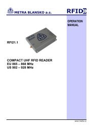
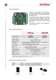
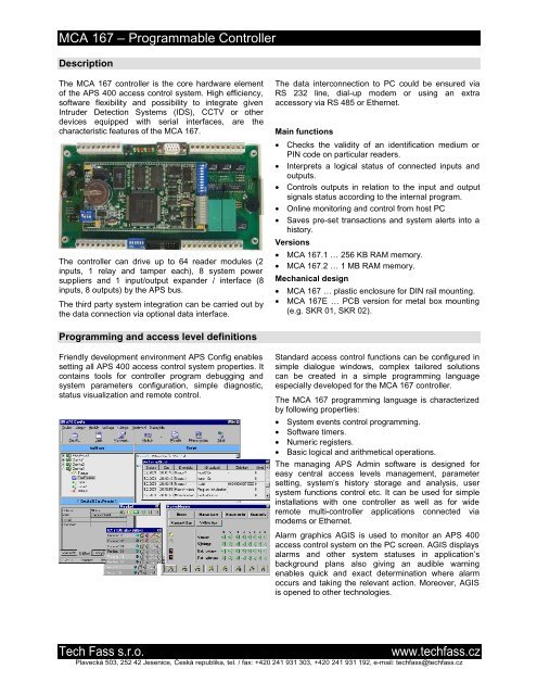
<strong>MCA</strong> <strong>167</strong> á Programmable ControllerDescriptionThe <strong>MCA</strong> <strong>167</strong> controller is the core hardware elementof the APS 400 access control system. High efficiency,software flexibility and possibility to integrate givenIntruder Detection Systems (IDS), CCTV or otherdevices equipped with serial interfaces, are thecharacteristic features of the <strong>MCA</strong> <strong>167</strong>.The controller can drive up to 64 reader modules (2inputs, 1 relay and tamper each), 8 system powersuppliers and 1 input/output expander / interface (8inputs, 8 outputs) by the APS bus.The third party system integration can be carried out bythe data connection via optional data interface.The data interconnection to PC could be ensured viaRS 232 line, dial-up modem or using an extraaccessory via RS 485 or Ethernet.Main functions• Checks the validity of an identification medium orPIN code on particular readers.• Interprets a logical status of connected inputs andoutputs.• Controls outputs in relation to the input and outputsignals status according to the internal program.• Online monitoring and control from host PC• Saves pre-set transactions and system alerts into ahistory.Versions• <strong>MCA</strong> <strong>167</strong>.1 ’ 256 KB RAM memory.• <strong>MCA</strong> <strong>167</strong>.2 ’ 1 MB RAM memory.Mechanical design• <strong>MCA</strong> <strong>167</strong> ’ plastic enclosure for DIN rail mounting.• <strong>MCA</strong> <strong>167</strong>E ’ PCB version for metal box mounting(e.g. SKR 01, SKR 02).Programming and access level definitionsFriendly development environment APS Config enablessetting all APS 400 access control system properties. Itcontains tools for controller program debugging andsystem parameters configuration, simple diagnostic,status visualization and remote control.Standard access control functions can be configured insimple dialogue windows, complex tailored solutionscan be created in a simple programming languageespecially developed for the <strong>MCA</strong> <strong>167</strong> controller.The <strong>MCA</strong> <strong>167</strong> programming language is characterizedby following properties:• System events control programming.• Software timers.• Numeric registers.• Basic logical and arithmetical operations.The managing APS Admin software is designed foreasy central access levels management, parametersetting, system±s history storage and analysis, usersystem functions control etc. It can be used for simpleinstallations with one controller as well as for wideremote multi-controller applications connected viamodems or Ethernet.Alarm graphics AGIS is used to monitor an APS 400access control system on the PC screen. AGIS displaysalarms and other system statuses in application±sbackground plans also giving an audible warningenables quick and exact determination where alarmoccurs and taking the relevant action. Moreover, AGISis opened to other technologies.Tech Fass s.r.o.www.techfass.czPlavecka 503, 252 42 Jesenice, C eska republika, tel. / fax: +420 241 931 303, +420 241 931 192, e-mail: techfass@techfass.cz
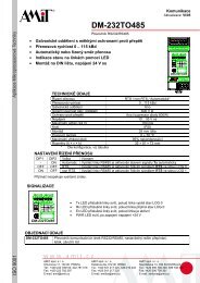
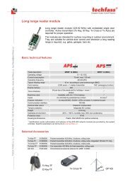
<strong>MCA</strong> <strong>167</strong> á Programmable ControllerHost PCThird party technologiesAPS BUSCONTROLLERWGDWGDRS 232PSUProgrammableControllerReader ModuleUp to 64 per ConttollerDual Wiegand InterfaceUp to 32 per ControllerWiegand InterfaceUp to 64 per ControllerComm. Interface, I/O Expander1 per ControllerPower SupplierUp to 8 per ControllerSoftware featuresNumber ofReader modules 64System power suppliers 8CapacityThird party interface 1Number of cards 7000 / 20000 *)Access groups 128Time frames 64Holidays 64Transactions 2000 / 4500 *)*) <strong>MCA</strong> <strong>167</strong>.2. If more than 20,000 user's ID are required, it is possible to delegate the authorization process to thesuperior computer (online operating mode is required). The other system functions stays unchanged. In this case itis possible to extend the number of the user's up to 10,000,000.Technical parametersDimensions12 DIN units, low profile module (PCB: 102x202mm)Supply voltage 12 VDC ÷ 15%Current demand200 mABack-up of RAM and RTC1000 mAh (5 years)Inputs8 logical1 tamper1 analogue 0° 24V (supervising of power supplier)Outputs2 relay dry change over contact 8A / 250V4 relay dry change over contact 1A / 24V2 open collector 100 mACommunication channelsRS 232 - connector X2 for PC or dial-up modemRS 485 - APS BUSSignalization6 LED1 buzzerWeight0.5 kg (PCB 0.3kg)Operating temperature-10 C ÷ 40 CHumidity75% non condensingTech Fass s.r.o.www.techfass.czPlavecka 503, 252 42 Jesenice, C eska republika, tel. / fax: +420 241 931 303, +420 241 931 192, e-mail: techfass@techfass.cz
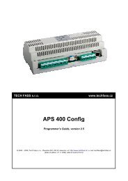
<strong>MCA</strong> <strong>167</strong> á Programmable ControllerFunction of each terminal, DIP switch, LEDTerminal C1 2 3 4 5 6 7 8 9RESETGYRRx0Tx0PWRTerminal DX2 - RS 232 1 2 3 4 5 6 7 8 9 10 11J3J5J41’ 4battCPUSW configurationLED indication110110HW configuration1 2 3 4 5 6 7 8 9 10 SW 61 2 3 4 5 6 7 8 9 101112Terminal ATerminal BTerminal block A1 ’ 0 V2 ’ input 13 ’ input 24 ’ input 35 ’ input 46 ’ input 57 ’ input 68 ’ input 79 ’ input 810 ’ analogue inputTerminal block B1 ’ NO relay 12 ’ NC relay 13 ’ C relay 14 ’ NO relay 25 ’ NC relay 26 ’ C relay 27 ’ NO relay 38 ’ C relay 39 ’ NC relay 3Jumpers J3, J4 and J5J3 ’ terminating resistor (RS 485)J4, J5 ’ idle state definition(RS 485)Terminal block C1 ’ +12 VDC (supply voltage)2 ’ 0 V3 ’ 0 V tamper contact4 ’ tamper contact5 ’ Shield RS 4856 ’ B wire RS 4857 ’ B wire RS 4858 ’ A wire RS 4859 ’ A wire RS 485Terminal block D1 ’ output OC12 ’ output OC23 ’ NO relay 44 ’ C relay 45 ’ NC relay 46 ’ NO relay 57 ’ C relay 58 ’ NC relay 59 ’ NO relay 610 ’ C relay 611 ’ NC relay 6HW configuration’ normal operating mode’ firmware downloadSW configuration1 ’ address bit 02 ’ address bit 13 ’ address bit 24 ’ address bit 35 ’ ON - multi-triggering thesame macro enabled6,7 ’ baud rate setting:00 ’ 9 600 Bd10 ’ 19 200 Bd01 ’ 38 400 Bd11 ’ 57 600 Bd8 ’ ON - modem9 ’ reserved6 ’ ON - RAM erasing afterRESETLED indication bar-graph1 ’ Tx1 (UART CPU)2 ’ Rx1 (UART CPU)3 ’ Tx0 (external UART)4 ’ Rx0 (external UART)5-9 ’ reserved10 ’ supply voltageLED indication - particular LEDG ’ communication restorationY ’ reservedR ’ reservedRX0 ’ APS BUSTX0 ’ APS BUSPWR ’ supply voltageTech Fass s.r.o.www.techfass.czPlavecka 503, 252 42 Jesenice, C eska republika, tel. / fax: +420 241 931 303, +420 241 931 192, e-mail: techfass@techfass.cz