User's guide - TECH FASS sro
User's guide - TECH FASS sro
User's guide - TECH FASS sro

Create successful ePaper yourself
Turn your PDF publications into a flip-book with our unique Google optimized e-Paper software.
<strong>TECH</strong> <strong>FASS</strong> s.r.o.<br />
www.techfass.cz<br />
APS 400 Config<br />
Programmer’s Guide, version 2.5<br />
© 2000 – 2008, Tech Fass s.r.o., Plavecka 503, 252 42 Jesenice, url: http://www.techfass.cz/, e-mail: techfass@techfass.cz<br />
(Date of edition: 27. 3. 2008, valid for build 2.5.0.0)
APS 400 Config – Programmer’s Guide<br />
1.1 Content<br />
1.1 Content ...................................................................................................................................................................... 2<br />
Installation, configuration and program environment .................................................................................................. 3<br />
2.1 Hardware and OS requirements ................................................................................................................................ 3<br />
2.2 Software installation and configuration .................................................................................................................... 3<br />
2.3 Main program window, desktop, tool bar, status bar ................................................................................................ 3<br />
2.4 Data files used ........................................................................................................................................................... 4<br />
2.5 Main menu commands summary .............................................................................................................................. 4<br />
2.6 Program set up .......................................................................................................................................................... 6<br />
2.7 Tools ......................................................................................................................................................................... 6<br />
Applications in APS Config environment ....................................................................................................................... 9<br />
3.1 Application structure and properties ......................................................................................................................... 9<br />
3.2 Modules .................................................................................................................................................................. 10<br />
3.3 Events and macros .................................................................................................................................................. 11<br />
3.4 Script ....................................................................................................................................................................... 12<br />
3.5 Program compilation, upload to the controller memory ......................................................................................... 13<br />
System programming ..................................................................................................................................................... 14<br />
4.1 Standard system functions ...................................................................................................................................... 14<br />
4.2 Macros .................................................................................................................................................................... 16<br />
Appendix.......................................................................................................................................................................... 22<br />
5.1 APS 400 system modules ....................................................................................................................................... 22<br />
5.2 APS 400 system devices ......................................................................................................................................... 25<br />
5.3 The most important macro-language constructions overview. ............................................................................... 29<br />
5.4 System archive marks summary ............................................................................................................................. 32<br />
5.5 Complete APS 400 application example ................................................................................................................ 34<br />
5.6 Programming protocol ............................................................................................................................................ 37<br />
- 2 -
Developmental environment<br />
2<br />
Installation, configuration and program environment<br />
The APS 400 Config software is a complex development tool for customization of the APS 400 access control<br />
system. It contains tools for system programming, simple diagnostics, visualization and status control.<br />
2.1 Hardware and OS requirements<br />
Recommended operating system is Microsoft Windows NT 4.0 (SP4) or higher ones (Windows 2000, Windows<br />
XP). HW equipment related to the used OS is necessary for efficient work. Monitor with resolution 1024x768<br />
pixels is suitable. Disc space requirements are minimal.<br />
2.2 Software installation and configuration<br />
The software is available free of charge, link to the latest installation files is located on the web site<br />
http://www.techfass.cz/aps_400_dn_cz.html. The APS 400 Config software can also be distributed on CD ROM<br />
or other media for a particular order.<br />
Follow the recommendations after running the installation file (setup.exe). No other configuration is<br />
necessary after finishing the set up procedure. The configuration file (APSConfig.ini) is being saved when<br />
exiting the program. When you change the parameters setting inappropriately and the default setting is<br />
demanded, simply close the program, erase the configuration file and run the program again.<br />
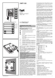
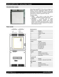
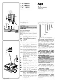
2.3 Main program window, desktop, tool bar, status bar<br />
APS Config main program window (fig. 2.1)<br />
contains standard parts (menu, tool bar, status<br />
bar ...).<br />
The desktop is divided into three basic parts:<br />
• Application tree … defines the hardware<br />
structure of the application.<br />
• Module inspector … displays and allows<br />
editing the object properties selected in the<br />
application tree.<br />
• Script editor … text editor for creation of a<br />
program defining the application behavior.<br />
All three parts are interrelated. Thus the<br />
changes in one of these parts cause changes in<br />
the other two ones automatically.<br />
application tree<br />
module inspector<br />
tool bar<br />
status line<br />
main menu<br />
script editor<br />
Fig. 2.1: Main program window<br />
- 3 -
APS 400 Config – Programmer’s Guide<br />
2.4 Data files used<br />
The application source file is saved as one file with the extension .apc. Any time when the file is opened a<br />
backup file is created in the same folder as the source file. It has the same name but behind its suffix the<br />
extension .bat is added. After the source program is compiled successfully the configuration file for<br />
administration software is saved in the same folder as the source file. It has the same name and .cfg extension.<br />
2.5 Main menu commands summary<br />
All commands located in the program main menu are described in the table in the fig. 2.3. In order to show the<br />
list complete, the table in fig. 2.2 contains also commands not included in the main menu (they can be run only<br />
by a keyboard shortcut). The function of the most of commands is the same as in the majority of common<br />
programs (file management, text editing, help…), therefore the commands specific for this program will be<br />
described in this text only.<br />
Name Shortcut Description<br />
Smart tag<br />
Fast constructions<br />
Find a module<br />
Indent a block to the right<br />
Indent a block to the left<br />
Ctrl+<br />
space<br />
Ctrl+J<br />
Ctrl+M<br />
Shift+<br />
Ctrl+I<br />
Shift+<br />
Ctrl+U<br />
To be used when writing the script – the command displays<br />
a list of modules and devices that can be at given place of<br />
the script used<br />
To be used when writing the script – the command displays<br />
a menu with pre-defined parts of the script that can be<br />
inserted into the editor<br />
To be used when writing the script – after the command is<br />
run the module corresponding to the currently edited macro<br />
is found (highlighted)<br />
Indents all selected lines 2 spaces to the right<br />
Indents all selected lines 2 spaces to the left (if it is possible)<br />
Fig.2.2: Commands not included in the main menu<br />
Menu / command caption Shortcut Description<br />
File Alt+S Working with files<br />
New - Creates a new (empty) file.<br />
Open - Opens an existing application file.<br />
Save - Saves the opened application file.<br />
Save as - Saves the opened application file under a new filename.<br />
Print - Prints out the applicaton report.<br />
Close Alt+F4 Closes the APS Config application.<br />
Last opened files - Four commands for opening the last opened files.<br />
Edit Alt+A Script editor tools<br />
Back Alt+ Takes back the last change in the script editor (if possible).<br />
Cut Ctrl+X Cuts the selected text into the windows clipboard.<br />
Copy Ctrl+C Copies the selected text into the windows clipboard.<br />
Paste Ctrl+V Pastes the text from the Windows clipboard into the script<br />
editor.<br />
Delete Del Deletes the text selected in the script editor.<br />
Select all Ctrl+A Selects all text in the script editor.<br />
Find - Opens the Find text dialog.<br />
Replace - Opens the Replace text dialog.<br />
Make comments Ctrl+K Converts lines selected in the script editor to the comments.<br />
Delete comments Ctrl+L Removes the comment marks form the lines selected in the<br />
script to editor (if the “;” mark is the first not-space character<br />
in the line).<br />
Collapse application tree Ctrl+B Collapses all nodes in the application tree.<br />
Sort macros - Sorts all macros in the script editor in the same order as<br />
defined in the application tree.<br />
Fig. 2.3: Main menu commands summary – the 1 st part<br />
- 4 -
Developmental environment<br />
Modules Alt+M Working with modules<br />
Delete module - Deletes the module selected in the application tree.<br />
Controller MCA 168 - Inserts the controller MCA 168 into the application tree.<br />
Network reader - Inserts the network reader module into the application tree.<br />
Application Alt+E Working with application<br />
Compile F9 Compiles the application to the binnary code.<br />
Upload script Alt+C Uploads the compiled binnary code to the controller, if the<br />
source file is changed the compilator is called before.<br />
Properties Alt+V Opens the Application properties dialog.<br />
Connect/Disconnect - Opens/closes the connection between the PC and the<br />
controller.<br />
Change application password - Opens the Change application password dialog.<br />
Tools Alt+R Visualisation and tuning<br />
Download cardholders - Downloads the card IDs table from the controller memory.<br />
Download access groups - Downloads the access goups setting from the controller<br />
memory.<br />
Download time zones - Downloads the time zones setting from the controller<br />
memory.<br />
Download holidays table - Downloads the holidays setting from the controller memory.<br />
Application parametres - Downloads all application parameters from the controller<br />
memory.<br />
Controller properties - Downloads the controller properties.<br />
Network status - Starts the network status visulaization.<br />
Master module status - Starts visualization of the controller status.<br />
Network reader status - Starts visualization of the selected network reader module<br />
status.<br />
Download events archive - Starts downloading of the access system events archive.<br />
Show registers - Starts visualization of the registers values.<br />
Show timers - Starts visualization of the timers values.<br />
Upload service setting - Uploads the service settings into the controller.<br />
Settings Alt+N Program parameters setting<br />
Script editor - Setting the script editor font and colors.<br />
Fast constructions - Opens the Fast constructions definition dialog.<br />
Communication servers - Opens the Customer communiaction servers paths dialog.<br />
Tools - Opens the Service settings definition dialog.<br />
Open scenario - Opens the saved scenario file.<br />
Save scenario - Saves current windows scenario into the selected file.<br />
Help - Working with help<br />
Contents F1 Opens the Help content.<br />
About - Opens the About application window.<br />
Fig. 2.3 Main menu commands summary – the 2nd part<br />
- 5 -
APS 400 Config – Programmer’s Guide<br />
2.6 Program set up<br />
Both the appearance and the behavior of the program at some operations can be influenced by APS Config<br />
software. Dialogs for all settings are activated with the commands from the Settings menu.<br />
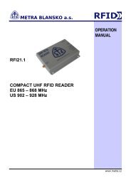
• Fast constructions are pre-defined parts of the text that can be<br />
inserted in the editor by hitting the keyboard shortcut CTRL+J.<br />
The dialog contains a list of defined constructions and buttons<br />
for their creation, editing and deletion. Two text parameters are<br />
defined for each construction: Menu title and Inserted text (fig.<br />
2.4) The Menu title can be any text displayed in the menu<br />
activated by the shortcut. The Inserted text is the text inserted in<br />
the script after the item in the menu is selected. The character<br />
“%” defines the position of cursor after text insertion.<br />
Fig. 2.4: Fast construction definitions<br />
• Standard comunication servers form a part of program<br />
installation. The description of setting up and configuration of non-standard communication servers can be<br />
found in the documentation enclosed.<br />
• Tools and environment dialog contains three folds to set:<br />
• ID codes of access cards and time plans.<br />
• ID code of designated card for validation of the reader module HW address setting (the modules<br />
supporting this function only) and a number of collected ID cards from the memory in case of controller<br />
diagnostics.<br />
• Colors used in the source text editor.<br />
• Reports setting dialog enables to insert a company logo and enter 4 lines of text information into the<br />
programming protocol. Insert bmp pictures only with the side ratio 2:1 to avoid their distortion during<br />
printing.<br />
• Commands Save scenario and Open scenario from Settings menu are used to enable recovering the settings of<br />
the position of visualization windows used before. Using the scenarios is conditional on online communication<br />
with the controller only.<br />
2.7 Tools<br />
The APS 400 Config software contains a number of tools that make the application design easier. All of these<br />
tools require online connection with the controller (more in chapter 3.1: Application structure and properties).<br />
The tools can be divided into three categories:<br />
• Tools for memory data check of the controller.<br />
• Tools for the system status visualization.<br />
• Tools for setting of the system parameters (service cards, HW address setting,..).<br />
Controller memory data check<br />
Tables of cardholders’ ID, access groups, time zones, holidays, application parameters and controller properties<br />
can be downloaded to a PC. Correct data collection is conditional on agreement of the application opened in APS<br />
Config software and the application uploaded in the controller.<br />
After the corresponding command is selected the inquiry is sent to the communication server and subsequently<br />
filled dialog with data downloaded is displayed. Each of these dialogs contains buttons OK and Cancel. Pushing<br />
any of these buttons closes the dialog. Pressing OK button saves the content of the table is into a text file, in<br />
which each line corresponds to one line of the table, and the columns are separated by semicolons.<br />
- 6 -
Developmental environment<br />
Particular text files are saved in the same folder as the<br />
APSConfig.exe file and their names are as follows:<br />
• ReportCards.txt … for cardholders’ ID.<br />
• ReportPlans.txt … for time zones.<br />
• ReportHolidays.txt … for holidays.<br />
• ReportParams.txt … for application parameters.<br />
• ReportGroups.txt and ReportIDS.txt … for access<br />
groups and related authorization flags.<br />
• ReportProperties.txt … for parameters of the controller.<br />
Fig. 2.5: Access groups<br />
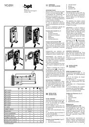
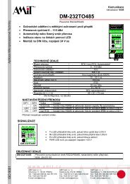
Some details related to the access groups download should be mentioned:<br />
The access level of particular access point is defined by a value saved in the intersection of the access group<br />
number assigned to the card ID and the particular access point reader HW address. At each intersection the<br />
general access (“A” – displayed in the green field), no access (“N” – in the red field) or access according to<br />
a time zone (the frame number is displayed – in the yellow field) can be defined, see fig. 2.5.<br />
If the access is not forbidden there is a possibility to define so called authorization flag (e.g. it can signify the<br />
authorization for IDS control). In case this flag is defined a black triangle is displayed in the right upper corner<br />
of the field. In the text file ReportIDS.txt these values are saved as “A” – flag is assigned and “N” – flag is<br />
not assigned.<br />
System visualization tools<br />
The tools for system status visualization allow on-line overview of all inputs, outputs and logical statuses of<br />
particular system modules, their remote control, user events activation, and, partially, APS Bus communication<br />
control. All visualization windows are “stays on top” and can be opened simultaneously. At the same time the<br />
APS Config program can be operated without any restrictions.<br />
The basic visualization tool is the network status monitoring (fig. 2.6). Every network reader module is<br />
represented by one icon showing its communication status. The modules that are not connected to the network<br />
are gray, standard communicating modules are green, the ones where the communication was lost and the<br />
controller has been trying to restore the communication again are red.<br />
Clicking any module icon by the mouse right button displays a local menu with<br />
following commands:<br />
Show details ... displays a window with detailed visualization of the module status.<br />
Connect module ... commands the controller to restore the communication with the<br />
module.<br />
Disconnect module ... commands the controller to disconnect the communication<br />
with the module.<br />
The detailed network reader status monitoring can be opened in two ways. Either<br />
from the Network status window as described above or using the Network reader<br />
status command from Tools menu. The status window (fig. 2.7) contains (from left):<br />
• An icon showing the communication status (it has the same meaning as in the Network status window).<br />
• Tamper input icon (yellow = activated).<br />
• Reading device icon (gray = not active, green = valid ID, blue = invalid ID, red =<br />
unknown ID).<br />
• Alarm status icons “Forced door“ and “Door ajar“.<br />
• Both inputs and outputs icons (green = open, red = close).<br />
Fig. 2.6: Network status<br />
Fig. 2.7: Network<br />
module<br />
- 7 -
APS 400 Config – Programmer’s Guide<br />
Power supplier status monitoring can be opened in the same way as the Network reader status. The status<br />
window (fig. 2.8) contains (from left):<br />
• An icon showing the communication status (it has the same meaning as in the Network status window).<br />
• Tamper input icon (yellow = activated).<br />
• AC current status icon (green = connected, red = disconnected).<br />
• Battery status icon (green = O.K., red = discharged, grey = disconnected).<br />
• DC output status icon (green = O.K., red = overloaded/short cut, black =<br />
Fig. 2.8: PSU status<br />
disconnected).<br />
For a detailed visualization of the controller status there is a<br />
Controller status window, see fig. 2.9. A part of the window is<br />
composed from the icons representing inputs and outputs and<br />
global logical system statuses. The rest of icons contain buttons<br />
whose meanig is obvious from their description.<br />
The outputs can be controlled from the local menu in all cases,<br />
accessible by clicking an appropriate icon which contains the dual<br />
command Connect and Disconnect.<br />
Exceptional standing has status visualization windows of registers<br />
and software timers Show registers and Show timers. It is necessary<br />
to compile the relevant application which is downloaded in the<br />
controller before to have correct overviews. Remote setting of both<br />
parameters is possible.<br />
The last tool of this category is the Download events archive command. The assumption of correct overview is to<br />
compile the relevant application downloaded in the controller before.<br />
Tools for setting up the system parameters<br />
Upload service setting to the controller makes the system debugging easy. Access levels defined in the Settings<br />
menu are uploaded to controller memory – there is no need to install server and administration software.<br />
Set reader HW address (fig. 2.10) is used for the reader<br />
modules which address can’t be set using a keypad, jumpers<br />
or DIP switch (e.g. NREM 61).<br />
Enter the desired HW address into particular field and hit the<br />
“Set” button. Then take the card set as the “setting one“ in<br />
the Settings menu and enclose it to the appropriate reader<br />
module. Address setting is acknowledged by a long beep.<br />
Do not set the same address as already present on the APS<br />
Bus!<br />
Fig. 2.9: Controller status<br />
Fig. 2.10: Setting up the network module<br />
address<br />
- 8 -
Applications in APS Config environment<br />
3<br />
Applications in APS Config environment<br />
3.1 Application structure and properties<br />
An application in APS Config environment defines the HW structure of the APS 400 system installation, its<br />
properties and script defining its behavior.<br />
The application hardware structure is displayed in the application tree. Every application contains following<br />
elements: one master module (MCA 168), up to 64 net reader modules and up to 8 system power suppliers<br />
(PSU 71). The particular modules can be inserted into the application tree by choosing the required module from<br />
the Modules menu or using a local menu accessible by clicking the right mouse button on the application tree.<br />
Modules can be removed from the application using the Delete module command from the same menu.<br />
Several properties of the application can be defined in the Application properties dialog (fig. 3.1), which can be<br />
displayed using the Properties command from Application menu. This dialog contains two folds: Application for<br />
general properties definitions and Connection for setting up the way of controller connection to a PC.<br />
General application properties are:<br />
Fig. 3.1: Application properties<br />
• Application name ... any text string, max 30 characters.<br />
• Compiler version ... number of the compiler version for which the application is created, this number can’t be<br />
changed.<br />
• Call back phone 1 and Call back phone 2 ... for applications connected via modem, the command for calling<br />
the upper system (PC) using one of these two phone numbers can be used in the script.<br />
• Application ID ... numerical identifier. It has a special meaning in case of modem connections (call back) only.<br />
• HW address … setting up HW address of the controller.<br />
- 9 -
APS 400 Config – Programmer’s Guide<br />
The way of system controller communication has to be defined in the fold of connection properties; connecting a<br />
MCA 168 controller is possible only by setting a TCP/IP connection to a communication server APS 400<br />
nServer.NET.<br />
• Serial line ... communication via RS 232 interface; connection parameter is the number of the serial port used.<br />
• Modem ... communication via modem; connection parameter is the controller phone number.<br />
• TCP/IP ... communication via computer network, connection parameter is the IP address of the server.<br />
• Other connection ... the communication is established in a different way of the modes of communication<br />
mentioned above. The way of setting up the non-standard communication modes is described in the manuals<br />
of appropriate communication software.<br />
• Locality password ... numerical code from interval , its value has to correspond to the value<br />
stored in the controller memory. The default value is “0”. This value is set in the controller after its restart<br />
while the switch DIP no.10 is switched on (se the manual of MCA 168 controller). The password can be<br />
changed after the communication is established using the Change application password command from the<br />
Application menu.<br />
3.2 Modules<br />
Every hardware module installed in the system is represented by an object having inputs, outputs and other<br />
periphery in the application tree. The general structure of the controller and a network module is evident from<br />
the following diagram (fig. 3.2).<br />
Fig. 3.2: Block diagrams of the controller and a network module<br />
Each module or device has a number of parameters defining its behavior and processing in administration<br />
software. They can be divided into three categories:<br />
• Properties … general definitions of properties of the modules or devices.<br />
• Events … system status change definitions due to the particular status change (e.g. switching on the input).<br />
• Descriptions … define a text assigned to every archive mark generated by the module or device if displayed.<br />
All of these parameters can be edited in the Module inspector (fig. 3.3) located in the left lower part of the main<br />
program window.<br />
Fig. 3.3: Module inspector<br />
- 10 -
Applications in APS Config environment<br />
Three properties are obligatory for all modules:<br />
• Name ... a unique text identifier of a module in the application. It can contain characters “A” .. “Z”, “a” .. “z”,<br />
“0” .. “9”, “_” and “-“. Up to 25 characters can be used for the name. The name can not be identical with any<br />
keyword of the macrolanguage or with any other name defined in the application.<br />
• ModuleID ... a unique number assigned to a module. It is assigned according to following rules:<br />
1) Controller ... Module ID = 0 (always)<br />
2) Network reader module ... Module ID = module HW address (1 – 64)<br />
3) Power supplier ... Module ID = module HW address (71 – 78)<br />
Similarly as the Name, also the ModuleID must be unique within an application.<br />
• Description ... it is any textual description of a module. It can be transfered to<br />
the administration software.<br />
Every device has an obligatory name (it is assigned implicitly and can not be changed). Set of data types<br />
properties and possibility of their editing can be seen in the table bellow (fig. 3.4).<br />
Data type Value range Example Editation<br />
Number 0..255 ModuleID Enter into the edit line<br />
Logical True, false SaveEvents Enter into the edit line, left mouse button<br />
double click<br />
Enumerated –<br />
reader module<br />
type<br />
General,<br />
Door,<br />
DoorWithHandle<br />
Text Any text string – up to 50<br />
characters<br />
Type<br />
(by the network<br />
reader module)<br />
Description<br />
Enter into the edit line, left mouse button<br />
double click<br />
Enter into the edit line<br />
Fig. 3.4: Data types<br />
The list of module/device events specifies all events that can trigger a macro. When an event occurs an archive<br />
mark is recorded into the system events archive (if its recording is allowed in the module properties)<br />
If a macro is created for any system event its name is displayed in the corresponding edit line of the Module<br />
inspector. If you wish to create a macro, double click on the edit line – the program will record the macro name<br />
into the Module inspector and will declare it simultaneously in the script.<br />
The list of archive marks descriptions enables editing of the text descriptions displayed when the system event<br />
archive is analyzed. The complete list of system archive marks can be seen in appendix 5.4. “System archive<br />
marks overview”.<br />
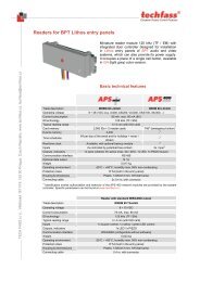
3.3 Events and macros<br />
The APS 400 program is<br />
performed via the controller,<br />
which detects the changes of<br />
status of its own and of all slave<br />
network modules. Based on this<br />
status changes the controller<br />
generates so called events, which<br />
can trigger related user programs<br />
– macros defining the reaction of<br />
the system. The way of generation<br />
and processing of events is shown<br />
in following diagram, fig. 3.5.<br />
Changes of input status<br />
Reading out the ID<br />
Change of logical status<br />
User’s action<br />
Save events<br />
allowed<br />
Events archive<br />
User’s program<br />
Configuration parameters<br />
Registers and timers<br />
Special counters<br />
Flags of ID<br />
Inputs and outputs<br />
status changes<br />
Save events<br />
allowed<br />
Events archive<br />
Figr. 3.5: The way of events processing<br />
- 11 -
APS 400 Config – Programmer’s Guide<br />
Within a macro processing, especially the Delay<br />
command, repeated activation of the same macro can<br />
appear. The controller has to decide if to interrupt the<br />
running macro (and execute it from the beginning) or leave<br />
it until finished. The behavior of the controller is<br />
determined by the setting up of the 5 th configuration DIP<br />
switch, see the MCA 168 manual.<br />
Note: Interrupting of macros is recommended in most of<br />
applications; in case of doubt ask your technical support.<br />
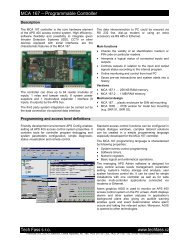
Most of the events are triggered by a status change of any<br />
peripheral device. Events activated by a user’s<br />
identification number (Valid, Invalid, Unknown) are<br />
processed a little more complicated. Thereafter the ID is<br />
read by a network reader, the controller decides which<br />
event to generate. The progress of this processing can be<br />
seen in fig. 3.6.<br />
The whole model of access rights is rather complex. It<br />
contains counters of present users, programmable flags<br />
fixed on particular ID and other mechanisms suitable for<br />
various types of applications. The description of this<br />
mechanism contains following documents:<br />
• http://www.techfass.cz/files/t_aps_400_opravneni_en.pd<br />
f.<br />
Detailed technical description of frequent applications:<br />
UNKNOWN<br />
• http://www.techfass.cz/files/t_aps_400_ijidelna_en.pdf,<br />
• http://www.techfass.cz/files/t_aps_400_iadministrator_vis_en.pdf.<br />
ID INPUT<br />
ID FOUND<br />
NO<br />
YES<br />
TIME<br />
YES<br />
FRAME<br />
NO<br />
HOLIDAY<br />
NO<br />
GENERAL YES<br />
YES<br />
ACCESS<br />
NO<br />
YES<br />
ACCESS<br />
GRANTED<br />
NO<br />
PARTITION<br />
YES<br />
ASSIGNED<br />
NO<br />
PARTITION<br />
ARMED<br />
NO<br />
YES<br />
INVALID<br />
VALID<br />
Fig. 3.6: Access rights<br />
YES<br />
ACCESS<br />
GRANTED<br />
NO<br />
YES<br />
IDS CONTR.<br />
AUTHORIZED<br />
NO<br />
3.4 Script<br />
The script contains all macros defining the system behavior, comments, and declarations of registers, timers, user<br />
archive marks and parameters.<br />
No upper case and lower case letters are distinguished; e.g. for the module name is valid:<br />
Reader1=reader1=READER1<br />
Macros<br />
Macro has following format:<br />
Event ModuleName.EventIdentifier<br />
… Body of macro …<br />
EventEnd<br />
The body of macro is composed of a sequence of commands defining the system behavior. The key words<br />
Event and EventEnd are obligatory and define the beginning and the end of the macro. ModuleName is the<br />
name assigned by a property Name in the module inspector. EventIdentifier is an implicitly defined name of<br />
a touched event and cannot be changed.<br />
Comments<br />
Comment is a part of the script beginning with the character “;”. All characters behind, up to the end of the line,<br />
are then ignored when the script is compiled. Comments serve for explaining more complicated parts of the<br />
program code, variables etc. It is recommended to use rich comments; they will help to facilitate understanding<br />
the program code when it is customized in the future.<br />
Event ModuleName.Event.Identifier<br />
; This is a comment<br />
EventEnd<br />
- 12 -
Applications in APS Config environment<br />
Registers<br />
Register is numerical variable valid globally in the whole script (in all macros). Any number from the<br />
interval can be written in the register and the value can be tested at other place of the script. Up to 250<br />
registers can be used in an application. Register declaration can be located at any place of the script but it is<br />
recommended to place all declarations at the beginning of the script.<br />
Register declaration has following format:<br />
Software timers<br />
Define register RegisterName<br />
Software timer is numerical variable as well as the register but with different meaning. If the timer value<br />
is set to 255 the timer switched off. If the value is less then 255 it is decremented every second by 1 until zero.<br />
The program can assign a numerical value to the timer (meaningful are values 1-254), which triggers countingdown<br />
the time interval corresponding to the assigned value in seconds. It can be tested anywhere in the script<br />
while the timing is still running (value > 0) or if it has already stopped (value = 0). If the condition for timer zero<br />
value is reached the value is set to 255 (the timer is switched off). Up to 254 software timers can be used in an<br />
application.<br />
Software timer declaration has a following format:<br />
User parameters<br />
Define timer TimerName<br />
User parameter is valid in the whole script too. It can be used as a parameter of the Delay command and it<br />
can assign a value to the register or the timer. Up to 254 users parameters can be used in an application.<br />
User parameter declaration has following format:<br />
Define parameter ParameterName=Value<br />
Using of the parameter is suitable when the same value has to be used in more program places or where the<br />
changes of its value from the administration software are required.<br />
User archive marks<br />
User archive marks are used for saving the particular program code passing into the events archive.<br />
Archive marks are valid in the whole script as well. Up to 254 users marks can be used in an application.<br />
User archive marks declaration has following format:<br />
Define mark MarkName=Description<br />
User archive marks are often used during the program debugging. In “sharp“ applications they can be used for<br />
storing the system statuses, which cannot be distinguished from the standard system archive marks.<br />
3.5 Program compilation, upload to the controller memory<br />
After the script is ready the application needs to be compiled to the code understandable for the controller. The<br />
compilation can be run using the Compile command from the Application menu. If there are no syntax errors<br />
found in the script the code can be uploaded to the controller (using the Upload script command) and the system<br />
behavior can be tested. In the opposite case, a list of found errors is displayed in the lower part of the editor. The<br />
compiler can check the syntax errors only, i.e. an error message appears if it does not “understand“ some part of<br />
the script. The compiler cannot find out any logical errors!<br />
Note 1: The macro is canceled if its body is empty during compilation.<br />
Note 2: When the module is renamed in the Module inspector the change comes out in the script editor<br />
automatically.<br />
- 13 -
APS 400 Config – Programmer’s Guide<br />
4<br />
System programming<br />
4.1 Standard system functions<br />
There are two ways of the standard functions programming in APS 400 Config environment:<br />
• "Manually" as described in the following chapters.<br />
• Using the configuration dialogs related to the standard programming of a particular module.<br />
Configuration dialog related to the selected module of application tree can be opened using the Standard<br />
function command from the Modules menu or from a local popup menu of the application tree.<br />
Function of configuration dialogs<br />
All functions performed in APS 400 access control system must be defined by the script or by setting up the<br />
values of some properties. The configuration dialogs generate the source texts of standard functions<br />
automatically based on entered values.<br />
Common items to configuration dialogs<br />
All configuration dialogs have following common items:<br />
• Text box Module name (in the script) for setting up the Name property.<br />
• Text box Module description (in the events archive) for setting up the Description property.<br />
• Defaults button - when pressed the default values of the module are set.<br />
Standard controller functions<br />
Global alarm warnings can be assigned to the controller<br />
in configuration dialog (fig. 4.1). Particular warning is<br />
activated through an optional controller output setting<br />
(Relay 1 - Relay 8).<br />
The alarm status of the output is configurable. Standard<br />
is NC contact. NO contact can be chosen by checking<br />
NO status.<br />
Meanings of particular alarm statuses and their default<br />
setting are listed in following table, see fig. 4.2.<br />
Fig. 4.1: Standard controller functions<br />
- 14 -
System programming<br />
Warning Meaning Output Status<br />
Tamper contacts<br />
At least one tamper contact was activated in the<br />
system (controller, netwok modules)<br />
Relay 1 Open<br />
Forced door At least one network module has Forced door status Relay 2 Open<br />
Door ajar At least one network module has Door ajar status Relay 3 Open<br />
Communication lost…<br />
The communication with at least one network module<br />
is lost<br />
Relay 4 Open<br />
Network module standard functions<br />
The way of door control can be defined in the Basic<br />
parameters fold; single or double sided control with<br />
any other reader module (choose the one in the list, see<br />
fig.4.3a). The text box for Module type definitions is<br />
the last item of this fold. The meanings of particular<br />
types are described bellow.<br />
It is strongly recommended to control the door from the<br />
more secure reader module (inside the building) in case<br />
of double sided control. The lower secure reader<br />
module then ensures reading out the media ID or a PIN<br />
code only and its output and inputs are free for other<br />
utilization.<br />
Fig. 4.2: Controller alarm warnings<br />
Advanced parameters<br />
The Advanced parameters fold (fig.4.3b) contains a<br />
text box for specifications of Strike time, Door ajar<br />
time (after expiration of this parameter a Door ajar<br />
warning is triggered – if the Module type is set to Door<br />
or DoorWithHandle) and the Last card timeout<br />
parameter.<br />
Fig. 4.3a: Network module standard functions<br />
Archive marks<br />
The “Archive marks“ fold contains a text box for text<br />
definitions of selected events.<br />
Defaults<br />
When this button is pushed the default settings of the<br />
module are recovered, i.e. single side door control,<br />
module type General, Strike time 5s, Door ajar 20,<br />
Last card timeout 1s, REX button checked. The<br />
descriptions of chosen events are set according to the<br />
fig. 4.3c.<br />
Fig. 4.3b: Network module standard functions<br />
Fig. 4.3c: Network module standard functions<br />
- 15 -
APS 400 Config – Programmer’s Guide<br />
4.2 Macros<br />
The body of macro is composed of a sequence of commands that should be carried out by the system after the<br />
macro is run. Particular commands are carried out sequentially in the order they were written in the body of<br />
macro. Only one command with an eventual comment can be placed on each line. The programmer can work<br />
with all modules and devices defined in the whole application in the body of the macro. Every device in the<br />
application has a unique identifier in following format:<br />
ModuleName.DeviceName<br />
Where ModuleName is the name assigned to the module in the property Name of module inspector, and<br />
DeviceName is the name of device generated by the environment. The names are unique within the module.<br />
Devices forming a part of the module generating a macro can be identified only by their names in the script (the<br />
compiler assumes automatically that the device is a part of the module that generates the event).<br />
The macro-language statements can be divided into three groups: assignments, conditions and system<br />
commands.<br />
Assignments<br />
Assignments enable the program to set the values of system outputs, registers and timers. The operator has<br />
following format:<br />
DeviceName=Value<br />
The type and range of used values depend on the type of status to be set. The On and Off values are to be used<br />
for the statuses of logical devices (inputs, outputs...), values within the interval for numerical values<br />
of registers and timers. Using of the operator is explained in the example 4.1. Two macros are defined in the<br />
example – for network reader module input (Input1) turned on and off. The macros copy the status of this input<br />
to the controller’s (MasterModule) output 1 (Relay1).<br />
Example 4.1: Macros for copying input status<br />
Event Reader1.Input1On<br />
MasterModule.Relay1=On<br />
EventEnd<br />
; macro for closing the Input1<br />
; turns the Relay1 on<br />
Event Reader1.Input1Off<br />
MasterModule.Relay1=Off<br />
EventEnd<br />
; macro for opening the Input1<br />
; turns the Relay1 off<br />
Conditions<br />
Simple logical expressions can be interpreted in the macro-language and the program can be branched on its<br />
base. Following construction serves for interpreting the logical expressions:<br />
If LogicalExpression then<br />
... body of the condition executed if the expression is true ...<br />
Else<br />
... body of the condition executed if the expression is false ...<br />
EndIf<br />
A shorter notation can be used if both conditions are not necessary:<br />
If LogicalExpression then<br />
... body of the condition ...<br />
EndIf<br />
The logical expression can test system input and output statuses, numerical values of registers, statuses of<br />
software timers and logical system variables. An overview of supported conditions is listed in appendix 5.3:<br />
“The most important constructions of APS 400 macro-language”.<br />
Only simple logical expressions can be interpreted in the conditions (only one logical status, one numerical value<br />
or one system status). The only logical operator used in logical expressions is NOT (negation). However, the<br />
conditions can be submerged (at maximum 20 conditions) and the absence of AND and OR operators can be<br />
substituted for an appropriate combination of logical conditions. Example 4.2 demonstrates substitution for the<br />
AND operator, example 4.3 for the OR operator, and the testing of system variables demonstrates example 4.4.<br />
- 16 -
System programming<br />
Example 4.2: Substitution for the AND operator (submerged conditions)<br />
Event Reader1.Input1On<br />
If Reader2.Input1=On then<br />
If Reader3.Input1=On then<br />
Relay1=On<br />
EndIf<br />
EndIf<br />
EventEnd<br />
Example 4.3: Substitution for the OR operator (conditions with the same body)<br />
Event Reader1.Input1On<br />
If Reader2.Input1=On then<br />
Relay1=On<br />
EndIf<br />
If Reader3.Input1=On then<br />
Relay1=On<br />
EndIf<br />
EventEnd<br />
Example 4.4: Testing of system logical variables.<br />
Event MasterModule.Input1On<br />
If AllCountersEmpty then<br />
Signal(Reader1,2)<br />
Else<br />
Signal(Reader1,4)<br />
EndIf<br />
EventEnd<br />
; nobody present<br />
; two short beeps of the Reader1 module<br />
; somebody present<br />
; one long beep of the Reader1 module<br />
Triggering of system functions<br />
The last group of commands ensures triggering of various functions implemented in the system itself. The<br />
overview of these functions is listed in appendix 5.3: “The most important constructions of APS 400 macrolanguage”.<br />
Using of the Signal command is shown in example 4.4.<br />
Registers<br />
Any value from interval can be assigned to the register, a constant can be added or subtracted, and the<br />
value can be tested in the condition.<br />
Basic commands for managing the registers are:<br />
RegisterName = Value<br />
RegisterName = RegisterName + constant<br />
RegisterName = RegisterName – constant<br />
If RegisterName = Value then<br />
If RegisterName > Value then<br />
Logical operator NOT can be used in both conditions.<br />
; assign value to the register<br />
; add constant to the register<br />
; subtract constant of the register<br />
; test the register value<br />
; test the register value<br />
- 17 -
APS 400 Config – Programmer’s Guide<br />
The register used as a branch condition of system status (standard operation / building evacuation) is shown in<br />
example 4.5.<br />
Connections and function of the system are as follows:<br />
A switch (e.g. an output from fire alarm system) determining the “Evacuation” status (switched ON =<br />
Evacuation, switched OFF = Standard operation) is connected to the input 1 of the controller. There are two net<br />
reader modules installed in the system. Their outputs (e.g. controlling the door locks) should be permanently<br />
turned on in case of the evacuation. The evacuation status signalization has to be indicated every 10 s by the<br />
reader modules.<br />
Example 5.6: Use of registers<br />
Define register Evacuation<br />
; register definition<br />
Event MasterModule.Init ; event from the script initialization<br />
If Input1=Off then ; testing input 1<br />
Evacuation = 0<br />
; setting status to Standard operation<br />
EndIf<br />
If Input1=On then ; testing input 1<br />
Evacuation = 1<br />
; setting status to Evacuation<br />
EndIf<br />
EventEnd<br />
Event MasterModule.Timer10sec ; event from hardware timer 10s<br />
If Evacuation = 1 then ; testing the Evacuation status<br />
Reader1.Beep = On ; switching on the beep of reader 1<br />
Reader2.Beep = On ; switching on the beep of reader 2<br />
Delay(2)<br />
; wait for 2s<br />
Reader1.Beep = Off ; switching off the beep of reader 1<br />
Reader2.Beep = Off ; switching off the beep of reader 2<br />
EndIf<br />
EventEnd<br />
Event MasterModule.Input1On ; event from setting the controller input 1<br />
Evacuation = 1 ; setting the Evacuation status<br />
Reader1.Relay1 = On ; switching on the reader 1 relay<br />
Reader2.Relay1 = On ; switching on the reader 2 relay<br />
EventEnd<br />
Event MasterModule.Input1Off ; event from resetting the controller input 1<br />
Evacuation = 0 ; setting the Normal activity status<br />
Reader1.Relay1 = Off ; switching off the reader 1 relay<br />
Reader2.Relay1 = Off ; switching off the reader 2 relay<br />
EventEnd<br />
Event Reader1.Valid ; valid card on reader 1<br />
If Evacuation = 0 then ; testing Standard operation status<br />
Door()<br />
; calling standard door function<br />
EndIf<br />
EventEnd<br />
Event Reader2.Valid ; valid card on reader 2<br />
If Evacuation = 0 then ; testing Standard operation status<br />
Door()<br />
; calling standard door function<br />
EndIf<br />
EventEnd<br />
- 18 -
System programming<br />
Software timers<br />
Setting and testing the software timers is analogous to the registers except adding or subtracting constants (not<br />
supported). Example 4.6 is extended example 4.5. The timer is used for acoustic signalization control during the<br />
evacuation.<br />
Expansions of connection are as follows:<br />
The siren (has to be activated for the first 2 minutes of evacuation) is controlled by an output 1 of the controller.<br />
The optical signalization (indicates the whole duration of evacuation period) is switched on and off by output 2<br />
of the controller.<br />
Example 4.6: Use of software timers<br />
Define register Evacuation<br />
Define timer Siren<br />
; register definition<br />
; timer definition<br />
Event MasterModule.Init ; event from the script initialization<br />
If Input1=Off then ; testing input 1<br />
Evacuation = 0<br />
; setting the status to the Standard operation<br />
Siren = 255 ; resetting the Siren timer<br />
Relay1 = Off ; switching off the optical indicator<br />
Relay2 = Off ; switching off the siren<br />
EndIf<br />
If Input1=On then ; testing the controller input 1<br />
Evacuation = 1<br />
; setting the Evacuation status<br />
Siren = 120 ; running the siren timer (120s)<br />
Relay1 = On ; switching on the optical indicator<br />
Relay2 = On ; switching on the siren<br />
EndIf<br />
EventEnd<br />
Event MasterModule.Timer1sec ; event from the hardware timer 1s<br />
If Siren = 0 then<br />
; siren time expired<br />
Relay2 = Off<br />
; switching off the siren<br />
EndIf<br />
EventEnd<br />
Event MasterModule.Timer10sec ; event from the hardware timer 10s<br />
If Evacuation = 1 then ; testing the evacuation status<br />
Reader1.Beep = On ; switching on the beep on reader 1<br />
Reader2.Beep = On ; switching on the beep on reader 2<br />
Delay(2)<br />
; waiting for 2s<br />
Reader1.Beep = Off ; switching off the beep on reader 1<br />
Reader2.Beep = Off ; switching off the beep on reader 2<br />
EndIf<br />
EventEnd<br />
Event MasterModule.Input1On ; event from setting the controller input 1<br />
Evacuation = 1 ; setting the Evacuation status<br />
Reader1.Relay1 = On ; switching on the reader 1 relay<br />
Reader2.Relay1 = On ; switching on the reader 2 relay<br />
Siren = 120 ; starting the Siren timer (120s)<br />
Relay1 = On ; switching on the optical indicator<br />
Relay2 = On ; switching on the siren<br />
EventEnd<br />
Event MasterModule.Input1Off ; event from resetting the controller input 1<br />
Evacuation = 0 ; setting the Normal activity status<br />
Reader1.Relay1 = Off ; switching off the reader 1 relay<br />
Reader2.Relay1 = Off ; switching off the reader 2 relay<br />
Siren = 255 ; resetting the Siren timer<br />
Relay1 = Off ; switching off the optical indicator<br />
Relay2 = Off ; switching off the siren<br />
EventEnd<br />
- 19 -
APS 400 Config – Programmer’s Guide<br />
Event Reader1.Valid ; valid card on reader 1<br />
If Evacuation = 0 then ; testing the Standard operation status<br />
Door()<br />
; calling standard door function<br />
EndIf<br />
EventEnd<br />
Event Reader2.Valid ; valid card on reader 2<br />
If Evacuation = 0 then ; testing the Standard operation status<br />
Door()<br />
; calling standard door function<br />
EndIf<br />
EventEnd<br />
User parameters<br />
User parameters can be used in following constructions:<br />
Delay(ParameterName)<br />
RegisterName= ParameterName<br />
RegisterName = ParameterName<br />
Delay(ParameterName)<br />
Typical use of user parameters is entering the time strike (after pushing a button or reading a valid card), see<br />
example 4.7.<br />
Connections and function are as follows:<br />
The door lock is connected to output 1 (Relay1) of the network reader module Reader1. The input 1 of Reader1<br />
module scans the door contact (turned on if the door is closed). The door lock is released after the input 2 of<br />
Reader1 module is switched on, and locked after the door is open or a time interval (defined by StrikeTime<br />
user parameter) is expired.<br />
Example 4.7: Use of user parameters<br />
Define parameter StrikeTime = 10<br />
; user parameter definition<br />
Event Reader1.Input2On ; event from pushing the button (Reader1,input2)<br />
If Input1=On then<br />
; testing the door status<br />
Relay1 = On ; releasing the strike<br />
Delay(StrikeTime)<br />
; waiting for the StrikeTime seconds<br />
Relay1 = Off ; locking the strike<br />
EndIf<br />
EventEnd<br />
Event Reader1.Input1Off<br />
Relay1 = Off<br />
EventEnd<br />
; event from disconnecting the door contact<br />
; locking the strike<br />
- 20 -
System programming<br />
Archive marks<br />
Archive marks can be stored into the archive using following command:<br />
Mark(MarkName)<br />
Example 4.8 is extended example 4.7. The system functionality is extended by the archive mark storing in case<br />
of the door stayed not open within the strike time interval.<br />
Example 4.8: Use of archive marks<br />
Define parameter StrikeTime=10 ; definition of the user parameter<br />
Define register DoorOpened<br />
; definition of the register<br />
Define mark DoorNotOpened=Door was not opened ; definition of the<br />
; archive mark<br />
Event MasterModule.Init<br />
DoorOpened=0<br />
EventEnd<br />
; event from the script initialization<br />
; setting the register value<br />
Event Reader1.Input2On ; event from setting the reader 1 input 2<br />
If Input1=On then<br />
; testing the Door status<br />
DoorOpened = 0<br />
; setting the register<br />
Relay1 = On ; releasing the strike<br />
Delay(StrikeTime)<br />
; waiting for the defined time [s]<br />
Relay1 = Off ; locking the strike<br />
If DoorOpened=0 then<br />
; testing the register value<br />
Mark(DoorNotOpened)<br />
; putting the archive mark into the archive<br />
EndIf<br />
EndIf<br />
EventEnd<br />
Event Reader1.Input1Off<br />
Relay1 = Off<br />
DoorOpened = 1<br />
EventEnd<br />
; event from disconnecting the door contact<br />
; locking the strike<br />
; setting the register value<br />
- 21 -
APS 400 Config – Programmer’s Guide<br />
5<br />
Appendix<br />
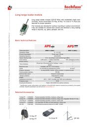
5.1 APS 400 system modules<br />
MCA 168 controller<br />
MCA 168 controller– properties<br />
Name Type Description<br />
Defines a unique text identifier of the module. The module is<br />
Name<br />
text represented by this identifier in the script. Characters (‘0..9’, ‘a’..’z’,<br />
‘A’..’Z’, ’-‘, ‘_’ can be used for defining the Name.<br />
ModuleID<br />
numeric<br />
Defines the module numerical identifier for internal system use.<br />
It must be always equal to “0” for the controller.<br />
SaveEvents<br />
logical<br />
Defines whether the archive marks generated by the module should be<br />
saved in the events history archive.<br />
Description text Any text representing module in the administration software APS 400.<br />
MCA 168 controller– events<br />
Name<br />
Conditions for event triggering<br />
GlobalDoorAjar<br />
DoorAjar status transition (any door stayed open for a longer period then allowed).<br />
GlobalForcedDoor ForcedDoor status transition (any door forced in the system).<br />
GlobalDoorAjarOK GlobalDoorAjarOK status transition (the last DoorAjar status shut down).<br />
GlobalForcedDoorOK GlobalForcedDoorOK status transition (the last ForcedDoor status shut down).<br />
GlobalTamper<br />
Any module gets tampered.<br />
GlobalTamperOK The last tamper canceled in the system.<br />
GlobalCommLost Loss of any system module communication.<br />
GlobalCommRestore Communication with all system net modules gets restored.<br />
Init<br />
User program (script) is initialized.<br />
Reset<br />
After the controller reset.<br />
MCA 168 controller– descriptions<br />
Name<br />
Saving marks conditions<br />
GlobalDoorAjar<br />
GlobalDoorAjar event generation.<br />
GlobalForcedDoor GlobalForcedDoor event generation.<br />
GlobalDoorDoorAjarOK GlobalDoorAjarOK event generation.<br />
GlobalForcedDoorOK GlobalForcedDoorOK event generation.<br />
GlobalTamper<br />
GlobalTamper event generation.<br />
GlobalTamperOK GlobalTamperOK event generation.<br />
GlobalCommLost GlobalCommLost event generation.<br />
GlobalCommRestore GlobalCommRestore event generation.<br />
Init<br />
Init event generation.<br />
Reset<br />
Reset event generation.<br />
ModemConnection<br />
LineBusy<br />
At the remote connection to the system by a modem.<br />
At not successful upload via a modem thanks to line busy.<br />
MCA 168 controller– list of devices<br />
UserEvents, Timer1Sec, Timer10Sec, PSU, Beep, Tamper, Input1..Input8, Relay1.. Relay8.<br />
Fig. 5.1: MCA 168 controller<br />
- 22 -
Appendix<br />
Network reader module<br />
Network reader module – properties<br />
Name Type Description<br />
Defines a unique text identifier of the module. The module is<br />
Name<br />
Text<br />
represented by this identifier in the script. Characters (‘0..9’, ‘a’..’z’,<br />
‘A’..’Z’, ’-‘, ‘_’ can be used for defining the Name.<br />
ModuleID<br />
Number<br />
Defines the module numerical identifier for internal system use.<br />
It is equal to the module hardware address setting .<br />
SaveEvents<br />
Logical<br />
Defines whether the archive marks generated by the module should be<br />
saved into the events history archive.<br />
Type<br />
Enumerated –<br />
reader<br />
Defines the reader behaviour. Detailed description of the module types<br />
contains the table on fig.5.3.<br />
module type<br />
StrikeTime Number Maximum door strike release time [s] (used by the Door function).<br />
AjarTime<br />
Number<br />
Restriction of door open period, when elapsed, the DoorAjar status is<br />
set.<br />
CardTimeout<br />
Number<br />
Period during which the last read access card is ignored by this<br />
module.<br />
Description Text Any text representing module in the administration software APS 400.<br />
Network reader module – events<br />
Name<br />
Event triggering conditions<br />
DoorAjar<br />
DoorAjar status transition.<br />
ForcedDoor<br />
ForcedDoor status transition.<br />
Network reader module – archive marks<br />
Name<br />
Saving marks conditions<br />
DoorAjar<br />
DoorAjar event generation.<br />
ForcedDoor<br />
ForcedDoor event generation.<br />
CommLost<br />
CommRestore<br />
Loss of the module communication.<br />
Restoring of the module communication.<br />
Network reader module – list of devices<br />
Tamper, Beep, CardReader, Input1, Input2, Relay1, LED3 (Relay2)<br />
Type property<br />
Fig. 5.2: Network reader module<br />
The Type property of the network reader needs a detailed explanation of its operation in Standard<br />
connection using the Door command.<br />
The standard connection of the reader module supposes the door contact connected to the first module input<br />
(door closed = door contact closed), the door lock connected to the first relay (NO, NC), and optional handle<br />
contact (handle down = handle contact closed) connected to the second module input. Wiring diagrams for<br />
various types of door locks and openers are on http://www.techfass.cz/aplikace_en.html.<br />
The basic solutions of settings the module type at calling the Door function are shown in examples 5.1, 5.2 and<br />
5.3. It is recommended to test the function on an operating system during studying the examples and also test the<br />
system behavior at changes of the StrikeTime, AjarTime and CardTimeout properties.<br />
Type<br />
General<br />
Door<br />
DoorWithHandle<br />
Meaning and usage<br />
General module not programmed in a standard way.<br />
Module programmed as standard with connected door control. Reports forced door and door<br />
ajar status automatically.<br />
Module programmed as standard controllig door with handle from inside. Handle contact is<br />
connected to the 2 nd module input. Reports forced door and door ajar status automatically<br />
with respect to the handle status.<br />
Fig. 5.3: Meaning and usage of Type property<br />
Door function<br />
Triggering of the Door function actuates simultaneously the output relay and beeper untill the door is open (door<br />
contact is disconnected) or the preset interval StrikeTime is elapsed. In case of non-authorized entry (i.e.<br />
- 23 -
APS 400 Config – Programmer’s Guide<br />
disconnecting the door contact without preceding controller command or handle pulling) the ForcedDoor event<br />
is triggered. If the door stays open until the pre-defined parameter AjarTime expires, the DoorAjar event is<br />
activated.<br />
ForcedDoor event<br />
The ForcedDoor event can be activating by the modules using type property set to Door or<br />
DoorWithHandle. In both cases triggering of the event is conditional on disconnecting the 1 st module input at<br />
non-actuated output relay status. Moreover the 2 nd module input cannot be connected (handle down) in the<br />
DoorWithHandle module type, it is considered as authorized door open.<br />
DoorAjar event<br />
The DoorAjar event is activating by the modules using type property set to Door or DoorWithHandle when<br />
the door stays open (the 1 st module input is open) after the pre-defined parameter AjarTime expires. If the<br />
module occurs in ForcedDoor status the DoorAjar is not reported.<br />
Examples:<br />
Example 5.1: Single side door control by Reader1 module, type DoorWithHandle,<br />
handle connected to the 2 nd module input.<br />
Event Reader1.Valid<br />
Door() ; Door open based on valid user’s identification.<br />
EventEnd<br />
Example 5.2: Single side door control by Reader1 module, type Door, REX button<br />
connected to the 2 nd module input.<br />
Event Reader1.Valid<br />
Door() ; Door open based on valid user’s identification.<br />
EventEnd<br />
Event Reader1.Input2On<br />
Door() ; Door open based on pushing the REX button.<br />
EventEnd<br />
Example 5.3: Double side door control by the twin of reader modules, type of<br />
Reader1 – Door, type of Reader2 – General, door connected to the Reader1<br />
module.<br />
Event Reader1.Valid<br />
Door()<br />
EventEnd<br />
Event Reader2.Valid<br />
Door(Reader1)<br />
EventEnd<br />
- 24 -
Appendix<br />
Power supply unit<br />
System PSU – properties<br />
Name Type Description<br />
Defines a unique text identifier of the module. The module is<br />
Name<br />
Text represented by this identifier in the script. Characters (‘0..9’, ‘a’..’z’,<br />
‘A’..’Z’, ’-‘, ‘_’ can be used for defining the Name.<br />
ModuleID<br />
Number<br />
Defines the module numerical identifier for internal system use.<br />
It is equal to the module hardware address setting .<br />
Description Text Any text representing module in the administration software APS 400.<br />
System PSU – events<br />
Name<br />
Event triggering conditions<br />
StatusChanged<br />
At any flags or tamper change.<br />
System PSU – archive marks<br />
Name<br />
Saving marks conditions<br />
CommLost<br />
Loss of the module communication.<br />
CommRestored<br />
Restoring of the module communication.<br />
DCOverload<br />
Output overloaded.<br />
DCOK<br />
Output O.K.<br />
BatteryLow<br />
Battery discharged<br />
BatteryOK<br />
Battery O.K.<br />
ACLost<br />
Loss of mains.<br />
ACRestorted<br />
Mains restored.<br />
BatteryConnected Battery connected.<br />
BatteryDisconected Battery disconnected.<br />
DCOn<br />
Output voltage turned on.<br />
DCOff<br />
Output voltage turned off.<br />
System PSU – list of devices<br />
Flags, Tamper<br />
Fig.5.4: System power supplier PSU 71<br />
5.2 APS 400 system devices<br />
Every APS 400 device type properties, events and archive marks are detailed described in this chapter. If more<br />
than one device occur in a module the devices are differed by a serial number (e.g. Input1, Input2, …)<br />
generally marked (InputX, OutputX, …) where X is the device serial number.<br />
Beep device<br />
Beep device represents the module beeper, which status can be controlled by assignment command (values On,<br />
Off) and it can be used as Invert function argument.<br />
Name<br />
Beep device – properties<br />
Name Type Description<br />
Text<br />
Defines the unique text identifier within the parent module. It is<br />
assigned automatically by the environment and cannot be changed.<br />
Fig. 5.10: Beep device<br />
- 25 -
APS 400 Config – Programmer’s Guide<br />
CardReader device<br />
CardReader device represents reading part of network modules; its status cannot be software controlled. After<br />
the card ID is read its validity (fig. 3.6) is analyzed and related event Valid, Invalid or Unknown is triggered.<br />
Saving the archive marks of this device cannot be forbidden.<br />
CardReader device – properties<br />
Name Type Description<br />
Name<br />
Text<br />
Defines the unique text identifier within the parent module. It is<br />
assigned automatically by the environment and cannot be changed.<br />
CardReader device – events<br />
Name<br />
Event triggering conditions<br />
Valid<br />
Reading valid card ID.<br />
Invalid<br />
Reading invalid card ID.<br />
Unknown<br />
Reading unknown card ID.<br />
Invalid PIN<br />
Invalid PIN code 5 times over entered.<br />
CardReader device – archive marks<br />
Name<br />
Saving marks conditions<br />
Valid<br />
At Valid event.<br />
Invalid<br />
At Invalid event.<br />
Unknown<br />
At Unknown event.<br />
Flags device (PSU 71)<br />
Fig. 5.11: CardReader device<br />
Power supply unit Flags device represents particular status information of PSU 71 power supplier. The statuses<br />
can be tested in condition commands, see example 5.6.<br />
Name<br />
Flags device – properties<br />
Name Type Description<br />
Text<br />
Defines the unique text identifier within the parent module. It is<br />
assigned automatically by the environment and cannot be changed.<br />
Fig.5.14: PSU71 Flags device<br />
Example 5.6: Testing the PSU 71 power supplier flags<br />
Event PSU71.StatusChanged ; status change of PSU (HW address=71)<br />
If not Flags(fACPresent) then ; test of AC present flag<br />
MasterModule.Relay1=On ; activation of the controller relay1<br />
; e.g. for signaling (optic or acoustic)<br />
EndIf<br />
EventEnd<br />
List of all sense flags; see the table in fig. 5.15.<br />
Flag<br />
fOverload<br />
fBatteryPresent<br />
fLowBattery<br />
fBoxTamper<br />
fDCOn<br />
fACPresent<br />
Output overloaded.<br />
Battery connected.<br />
Discharged battery.<br />
PSU box tampered.<br />
Output voltage turned on.<br />
Mains on.<br />
Meaning<br />
Fig.5.15: List of PSU 71 flags<br />
- 26 -
Appendix<br />
InputX device<br />
InputX represent the X th<br />
– module input. Its status cannot be software controlled but can be tested.<br />
InputX – properties<br />
Name Type Description<br />
Name<br />
Text<br />
Defines the unique text identifier within the parent module. It is<br />
assigned automatically by the environment and cannot be changed.<br />
SaveEvents<br />
Logical<br />
Defines whether the archive marks generated by the device should be<br />
saved into the events history archive.<br />
InputX – events<br />
Name<br />
Event triggering conditions<br />
InputXOn<br />
InputX close.<br />
InputXOff<br />
InputX open.<br />
InputX – archive marks<br />
Name<br />
Saving marks conditions<br />
InputXOn<br />
At the InputXOn event.<br />
InputXOff<br />
At the InputXOff event.<br />
PSU (Power Supply Unit) device<br />
Fig. 5.17: Inputs<br />
PSU device represents an extra controller input determined for standard (not APS bus connectible) power<br />
supplier output connection. Its status can be tested by condition command.<br />
PSU device – properties<br />
Name Type Description<br />
Name<br />
Text<br />
Defines the unique text identifier within the parent module. It is<br />
assigned automatically by the environment and cannot be changed.<br />
SaveEvents<br />
Logical<br />
Defines whether the archive marks generated by the device should be<br />
saved into the events history archive.<br />
PSU device – events<br />
Name<br />
Event triggering conditions<br />
PSUOn<br />
Output voltage O.K.<br />
PSUOff<br />
Output voltage K.O.<br />
PSU device – archive marks<br />
Name<br />
Saving marks conditions<br />
PSUOn<br />
At PSUOn event.<br />
PSUOff<br />
At PSUOff event.<br />
RelayX, AuxOutput<br />
Fig. 5.18: PSU device<br />
RelayX or AuxOutput device represent the hardware module outputs. The output status can be software<br />
controlled using assignment command (values On, Off can be assigned). The device can be used also as Invert<br />
function argument and can be tested.<br />
RelayX, AuxOutput device – properties<br />
Name Type Description<br />
Name<br />
Text<br />
Defines the unique text identifier within the parent module. It is<br />
assigned automatically by the environment and cannot be changed.<br />
SaveEvents Logical<br />
Defines whether the archive marks generated by the device should be<br />
saved into the events history archive.<br />
RelayX, AuxOutput device – archive marks<br />
Name<br />
Saving marks conditions<br />
RelayXOn,<br />
AuxOutputOn<br />
RelayX, AuxOutput close.<br />
RelayXOff,<br />
AuxOutputOff<br />
RelayX, AuxOutput open.<br />
Fig. 5.20: Relays<br />
- 27 -
APS 400 Config – Programmer’s Guide<br />
Tamper device<br />
Tamper device represents a module protective contact. It triggers particular event and can be tested in<br />
conditional commands. Any module tamper status change influences the system GlobalTamper status.<br />
Tamper device – properties<br />
Name Type Description<br />
Name<br />
Text<br />
Defines the unique text identifier within the parent module. It is<br />
assigned automatically by the environment and cannot be changed.<br />
Tamper device – events<br />
Name<br />
Event triggering conditions<br />
Tamper<br />
Switching tamper contact off.<br />
Tamper device – archive marks<br />
Name<br />
Saving marks conditions<br />
Tamper<br />
Tamper event triggering.<br />
Tamper OK<br />
Switching tamper contact on.<br />
Timer1sec, Timer10sec device<br />
Fig. 5.23: Tamper device<br />
Timer1sec or Timer10sec represents controller hardware timers. These timers generate event each 1s, or each<br />
10s and macros can respond to these events. It is necessary to keep in view the macros are called periodically<br />
and their code has to be executed before next triggering the same macro. Therefore it is not available to use<br />
commands Delay and Door or to control the IDS panel.<br />
Timer1sec, Timer10sec device – properties<br />
Name Type Description<br />
Name<br />
Text<br />
Defines the unique text identifier within the parent module. It is<br />
assigned automatically by the environment and cannot be changed.<br />
Timer1sec, Timer10sec device – events<br />
Name<br />
Event triggering conditions<br />
Timer1sec<br />
Events Timer1sec, or Timer10sec are triggered by the system each 1s, or each 10s.<br />
Timer10sec<br />
UserEvents device<br />
Fig. 5.24: Timer1sec, Timer10sec device<br />
UserEvents device represents 8 events, which can be generated from a host PC. User events can also be<br />
triggered from other macros by Execute(X) command, where X is the user event number. Execute command<br />
cannot be used in user events macros.<br />
UserEvents device – properties<br />
Name Type Description<br />
Name<br />
Text<br />
Defines the unique text identifier within the parent module. It is<br />
assigned automatically by the environment and cannot be changed.<br />
SaveEvents Logical<br />
Defines whether the archive marks generated by the device should be<br />
saved into the events history archive.<br />
UserEvents device – events<br />
Name<br />
Event triggering conditions<br />
UserEvent1<br />
Sending a command to trigger the UserEventX from host PC or calling the Execute(X)<br />
…<br />
function from any macro in the script.<br />
UserEvent8<br />
UserEvents device – archive marks<br />
Name<br />
Saving marks conditions<br />
UserEvent1<br />
…<br />
At UserEventX event.<br />
UserEvent8<br />
Fig. 5.26: UserEvents device<br />
- 28 -
Appendix<br />
5.3 The most important macro-language constructions overview.<br />
With respect to continuous increasing of APS 400 system functionality we recommend to update this list<br />
occasionally on http://www.techfass.cz/aps_400_macrolanguage_en.html. Also you can find there the links,<br />
examples and other related information sources. The list bellow corresponds to the controller firmware version<br />
202 and the compiler version 2.15 from the 6 th of July 2005.<br />
Break<br />
Terminates the macro executing; can be used in all events.<br />
ClearAllCounters<br />
Deletes all PRESENT flags of access cards and clears access groups and users’ codes counters of present<br />
cardholders at the same time; can be used in all events.<br />
ClearGroupCounter(x)<br />
Clears the access group counter of present cardholders defined by parameter x, deletes PRESENT flags of all<br />
cards assigned to defined access group and decrements adequate the user’s code counter; can be used in all<br />
events.<br />
ClearPresent<br />
Deletes PRESENT flag of just read access card and clears the relevant access group and user’s code counters of<br />
present cardholders at the same time; can be used in Valid event.<br />
ClearUserCounter(x)<br />
Clears the user’s code counter of present cardholders defined by parameter x, deletes PRESENT flags of all cards<br />
assigned to access groups with x user’s code set and decrements adequate the access groups counters; can be<br />
used in Valid event.<br />
Define mark x=Description<br />
Archive mark definition; it is entered beside the macros to the script.<br />
Define parameter x=Name<br />
Parameter definition; it is entered beside the macros to the script.<br />
Define register x=Name<br />
Numerical register definition; it is entered beside the macros to the script.<br />
Define timer x=Name<br />
Software timer definition; it is entered beside the macros to the script.<br />
Delay(x)<br />
Stops the macro executing for a pre-defined time in seconds defined by x parameter; can be used in all events<br />
except Timer1sec and/or Timer10sec.<br />
Dial(x,y)<br />
Establishes modem connection to a host PC. X parameter defines index of dialed phone number (1 or 2);<br />
y parameter defines the user archive mark describing the reason of the connection; can be used in all events.<br />
Display(x) / Display(ReaderN,X)<br />
Displays a symbol on current module, or ReaderN module (if the hardware contains the display). Meaning of x<br />
parameter is as follows:<br />
0 - 9 ... digit 0 - 9<br />
10 ... hyphen<br />
11 ... three level lines<br />
12 ... E character<br />
- 29 -
APS 400 Config – Programmer’s Guide<br />
13 ... decimal point<br />
14 ... all segments on (inc. decimal point)<br />
15 ... all segments off<br />
Door() / Door (ReaderN)<br />
Executes standard Door function; can be used in all events.<br />
EraseCard<br />
Erases the current card from controller memory table; can be used in Valid event.<br />
Execute(x)<br />
Activates the user event defined by x parameter; can be used in all events except the UserEventN events<br />
(recursion not allowed).<br />
If AllCountersEmpty then<br />
Evaluates the zero status of all access groups and user’s code counters of present cardholders; can be used in all<br />
events.<br />
If Authorized then<br />
Evaluates extra authorization flag of cardholder’s access levels; can be used in Valid event.<br />
If Buffer(x) then<br />
Checks filling in the controller events archive buffer if filled up more then defined by x parameter (in<br />
percentage) the result is true; can be used in all events.<br />
If Byte1=x then<br />
Compares entered value x to the value stored in Byte1 column of just read card ID. If the values match the result<br />
is true; can be used in Valid and/or Invalid events.<br />
If Byte2=x then<br />
Compares entered value x to the value stored in Byte2 column of just read card ID. If the values match the result<br />
is true; can be used in Valid and/or Invalid event.<br />
If Group(x) then<br />
Evaluates assignment of current card ID to the access group no. x; can be used in Valid event.<br />
If GroupEmpty(x) then<br />
Evaluates the zero status of access group no. x counter of present cardholders; can be used in all events.<br />
If KeyCode(x) then<br />
Compares the pressed key code on the reader module with reason keypad to entered code x; can be used in Valid<br />
event.<br />
If ModuleLost(x) then<br />
Checks the communication status of the network module with hardware address x the result is true if the<br />
communication is not established; can be used in all events.<br />
If Present then<br />
Evaluates the PRESENT flag of current card ID; can be used in Valid event.<br />
If TimePlan(x) then<br />
Evaluates the current validity of the time zone no. x; can be used in all events.<br />
- 30 -
Appendix<br />
If User(x) then<br />
Evaluates if the x number is equal to access group user’s code assigned to current card; can be used in Valid<br />
event.<br />
If UserEmpty(x) then<br />
Evaluates the zero status of present cardholders’ counter of the access groups with user’s code no. x assigned;<br />
can be used in all events.<br />
If x then ... endif / if x then ... else ... endif / if not x then ... endif / if not x then ... else ... endif<br />
Evaluates the x logical condition. The result can be negated using the not operator. Nesting depth is 20 levels;<br />
can be used in all events.<br />
Invert (x)<br />
Inverts the status of logical output defined by its name x; can be used in all events.<br />
Mark(x)<br />
Stores the archive mark defined by x name to controller events archive buffer; can be used in all events.<br />
SetByte1(x)<br />
Sets x value to Byte1 column of current card to the card ID table of the controller memory; can be used in Valid<br />
and/or Invalid event.<br />
SetByte2(x)<br />
Sets x value to Byte2 column of current card to the card ID table of the controller memory; can be used in Valid<br />
and/or Invalid event.<br />
SetModePIN(x)<br />
Switches over the defined reader module x to identification mode “card+PIN”. Reader modules with PIN pad<br />
only can be switched the other ones ignore this setting; can be used in all events.<br />
SetModePINFree(x)<br />
Switches over the defined reader module x to identification mode “card only”. Reader modules with PIN pad<br />
only can be switched the other ones ignore this setting; can be used in all events.<br />
SetPresent<br />
Sets the PRESENT flag to the current card and increments relevant access groups and user’s code counters of<br />
present cardholders; can be used in Valid event.<br />
- 31 -
APS 400 Config – Programmer’s Guide<br />
Signal(x) / Signal(ReaderN,X)<br />
Triggers the acoustic signal on current reader module, or ReaderN module. Meaning of x parameter is as follows:<br />
1 ... one short beep<br />
2 ... two short beeps<br />
3 ... three short beeps<br />
4 ... one long beep<br />
5 ... five short beeps<br />
6 ... erase card memory in the reader module<br />
5.4 System archive marks summary<br />
Event ID Description Event ID Description Event ID Description<br />
Controller archive marks (ModuleID=0)<br />
4 Input1 On 40 Reserved 132 Relay 3 On<br />
5 Input1 Off 41 Reserved 133 Relay 3 Off<br />
6 Input2 On 42 Reserved 134 Relay 4 On<br />
7 Input2 Off 43 Reserved 135 Relay 4 Off<br />
8 Tamper 45 Global door ajar 136 Relay 5 On<br />
16 Input3 On 46 Global forced door 137 Relay 5 Off<br />
17 Input3 Off 47 Global door ajar OK 138 Relay 6 On<br />
18 Input4 On 48 Timer 1 sec 139 Relay 6 Off<br />
19 Input4 Off 49 Timer 10 sec 140 Relay 7 On<br />
20 Input5 On 50 Init 141 Relay 7 Off<br />
21 Input5 Off 51 Global tamper 142 Relay 8 On<br />
22 Input6 On 52 Global tamper ok 143 Relay 8 Off<br />
23 Input6 Off 53 Global comm lost 144 Reserved<br />
24 Input7 On 54 Global comm restore 145 Reserved<br />
25 Input7 Off 55 PSU On 146 Reserved<br />
26 Input8 On 56 PSU Off 147 Reserved<br />
27 Input8 Off 60 User event 1 148 Reserved<br />
28 Reserved 61 User event 2 149 Reserved<br />
29 Reserved 62 User event 3 150 Reserved<br />
30 Reserved 63 User event 4 151 Reserved<br />
31 Reserved 64 User event 5 152 Reserved<br />
32 Reserved 65 User event 6 153 Reserved<br />
33 Reserved 66 User event 7 154 Reserved<br />
34 Reserved 67 User event 8 155 Reserved<br />
35 Reserved 68 Global forced door ok 156 Reserved<br />
36 Reserved 128 Relay 1 On 157 Reserved<br />
37 Reserved 129 Relay 1 Off 158 Reserved<br />
38 Reserved 130 Relay 2 On 159 Reserved<br />
39 Reserved 131 Relay 2 Off 160 LineBusy<br />
PC programming archive marks (ModuleID=253)<br />
0 Connected 2 Parametres upload - -<br />
1 Script upload 3 Access data upload - -<br />
Network module archive marks (ModuleID=HW address)<br />
1 Valid 7 Input2 Off 66 Comm. lost<br />
2 Invalid 8 Tamper 67 Comm. restored<br />
3 Unknown 9 DoorAjar 161 AuxOutput On<br />
4 Input1 On 10 Forced Door 162 AuxOutput Off<br />
5 Input1 Off 64 Relay1 On 249 Tamper OK<br />
6 Input2 On 65 Relay1 Off 250 Invalid PIN<br />
Fig. 5.28: System archive marks – the 1 st part<br />
- 32 -
Appendix<br />
PSU archive marks (ModuleID=HW address)<br />
8 Tamper 72 Battery low 77 Battery disconnected<br />
66 Comm. lost 73 Battery OK 78 DC On<br />
67 Comm. restored 74 AC Lost 79 DC Off<br />
70 DC overload 75 AC Restored 249 Tamper OK<br />
71 DC OK 76 Battery connected<br />
Fig. 5.28: System archive marks – the 2 nd part<br />
- 33 -
APS 400 Config – Programmer’s Guide<br />
5.5 Complete APS 400 application example<br />
Required system functions<br />
Simplified diagram of standard access control application is shown in figure 5.29. Application requirements are<br />
as follows:<br />
• The main entrance control should be both, from the readers or from handsets.<br />
• Current cardholders’ presence registration is required.<br />
• Door alarm and tamper alarm statuses should give a signal by audible and visual indicator. Audible<br />
signalization has to be active for a pre-set time after the alarm statuses are triggered or stopped using a button<br />
or host PC before the pre-set time is elapsed.<br />
• Door ajar status should give an optic signal only.<br />
Handset<br />
Handset<br />
REX<br />
S6<br />
Office 3<br />
Server room Office 2<br />
REX<br />
Handle<br />
S5<br />
S3<br />
Handset<br />
R5<br />
R2 R3<br />
S1<br />
R4<br />
S4<br />
REX<br />
Tamper indicator<br />
Forced door indicator<br />
R6<br />
Door ajar indicator<br />
Siren<br />
Stop siren<br />
Handset<br />
Office 1<br />
R1<br />
Audio/video entry panel<br />
Fig. 5.29: Simplified application diagram<br />
Hardware solution<br />
The main entrance double side reader control (R1, R2) is necessary because of the current cardholders’ presence<br />
registration is required. E.g. motor lock can be used for the main entrance. Door opening by the handset is used<br />
for visitors only.<br />
Server room door can be equipped e.g. by electric lock with handle contact and one reader module R3.<br />
The offices doors are fitted with door openers controlled by readers from outside and by request to exit (REX)<br />
buttons from inside.<br />
It is recommended to use locks and openers equipped by door contacts.<br />
- 34 -
Appendix<br />
Controller wiring – inputs:<br />
• Output relay of audio/video entry system … input 1<br />
• Reset button for acoustic signalization … input 2<br />
Controller wiring – outputs:<br />
• Siren … relay 1<br />
• “DoorAjar” status indicator … relay 3<br />
• “ForcedDoor” status indicator … relay 4<br />
• “TAMPER” status indicator … relay 5<br />
Inputs and outputs of reader modules are connected in standard way, see:<br />
http://www.techfass.cz/aplikace_en.html<br />
Note 1: It is necessary to ensure the emergency exit from inside areas according to the regulations of particular<br />
country independent of access control system operation!<br />
Software solution<br />
Insert MCA 168 controller (name MasterModule) and six network reader modules (name R1…R6) into APS<br />
Config application. Define modules descriptions (property Description) as follows:<br />
MCA168 controller… Master module<br />
R1<br />
… Main entrance<br />
R2<br />
… Main exit<br />
R3 … Office 1<br />
R4<br />
… Server<br />
R5 … Office 2<br />
R6 … Office 3<br />
Both (R1, R2) main entrance reader modules have different type set. R2 module (type Door is set) controls the<br />
door directly and generates the alarm signals, R1 module (type General is set) controls the door through the R2<br />
module. Exit and entry function of R1, R2 reader modules can be set in communication server software, see the<br />
manual: http://www.techfass.cz/files/m_aps_400_iserver_en.pdf<br />
R4 reader module is set (type DoorWithHandle). Other reader modules are set (type Door).<br />
List of the script:<br />
Define timer TMR1<br />
Define parameter PAR1=30<br />
Define parameter PAR2=30<br />
; software timer for siren timing<br />
; forced door status time interval<br />
; signaling<br />
; TAMPER status time interval<br />
; signaling<br />
Event Controller.GlobalDoorAjar<br />
Relay3=ON<br />
EventEnd<br />
; door ajar status optical signaling<br />
Event Controller.GlobalForcedDoor<br />
Relay4=ON<br />
; forced door status optical signaling<br />
TMR1=PAR1<br />
; starts audible signaling time interval<br />
EventEnd<br />
Event Controller.GlobalTamper<br />
Relay5=ON<br />
TMR1=PAR2<br />
EventEnd<br />
Event Controller.GlobalTamperOK<br />
TMR1=0<br />
Relay5=OFF<br />
EventEnd<br />
; TAMPER status visual signaling<br />
; starts audible signaling time interval<br />
; stops acoustic signaling<br />
; stops optical signaling<br />
- 35 -
APS 400 Config – Programmer’s Guide<br />
Event Controller.GlobalDoorOK<br />
Relay3=OFF<br />
Relay4=OFF<br />
TMR1=0<br />
EventEnd<br />
Event Controller.UserEvent1<br />
TMR1=0<br />
EventEnd<br />
Event Controller.Timer1sec<br />
If TMR1>0 then<br />
Invert(Relay1)<br />
Endif<br />
If TMR1=0 then<br />
Relay1=OFF<br />
Endif<br />
EventEnd<br />
Event Controller.Input2On<br />
TMR1=0<br />
EventEnd<br />
Event Controller.Input1On<br />
Door(R2)<br />
EventEnd<br />
; stops optical signaling<br />
; stops optical signaling<br />
; stops audible signaling<br />
; stops acoustic signaling by a PC<br />
; intermittent acoustic signal<br />
; stops acoustic signaling by the timer<br />
; stops acoustic signaling by a button<br />
; door function from entry system handset<br />
Event R1.Valid<br />
Door(R2)<br />
EventEnd<br />
Event R2.Valid<br />
Door()<br />
EventEnd<br />
Event R3.Valid<br />
Door()<br />
EventEnd<br />
Event R3.Input2On<br />
Door()<br />
EventEnd<br />
Event R4.Valid<br />
Door()<br />
EventEnd<br />
Event R5.Valid<br />
Door()<br />
EventEnd<br />
Event R5.Input2On<br />
Door()<br />
EventEnd<br />
Event R6.Valid<br />
Door()<br />
EventEnd<br />
Event R6.Input2On<br />
Door()<br />
EventEnd<br />
End of list.<br />
- 36 -
Appendix<br />
5.6 Programming protocol<br />
Every report page contains identical header and the bottom with its serial number. It is possible to modify the left<br />
part of a report header by setting some parameters, see chapter 2.6. “Program set up”.<br />
The report is divided into three parts:<br />
• General parameters … contains general information about the application, e.g. filename, date and time,<br />
connection type etc.<br />
• Modules list … contains the list of all modules (including subordinate devices) used in the application. List of<br />
all properties (normal font) and of archive marks description (italic font) is included.<br />
• Script … contains complete list of the script.<br />
- 37 -