smart-400 - Oeo.IT
smart-400 - Oeo.IT
smart-400 - Oeo.IT

You also want an ePaper? Increase the reach of your titles
YUMPU automatically turns print PDFs into web optimized ePapers that Google loves.
SICUREZZA GENERALE<br />
• L’automatismo SMART è conforme<br />
ai requisiti imposti dalle direttive<br />
2006/95/CEE (bassa tensione)<br />
e 2004/108/CEE (compatibilità<br />
elettromagnetica).<br />
• I collegamenti elettrici devono<br />
essere effettuati nel rispetto delle<br />
disposizioni legislative vigenti.<br />
• L’installatore deve istruire<br />
l’utilizzatore sul corretto<br />
funzionamento dell’automatismo,<br />
sulla manovra manuale<br />
d’emergenza e sui possibili rischi<br />
durante il funzionamento.<br />
• Prima di effettuare qualsiasi<br />
intervento sull’impianto togliere<br />
l’alimentazione elettrica.<br />
USO<br />
• Seguire tassativamente le<br />
indicazioni contenute nel<br />
foglio allegato “AVVERTENZE<br />
GENERALI PER LA SICUREZZA”.<br />
• In caso di manovra manuale seguire<br />
le indicazioni descritte al punto 7.<br />
• Consultare il manuale d’installazione<br />
e uso della centralina LOG-SB.<br />
MANUTENZIONE<br />
ORDINARIA<br />
(OGNI SEI MESI)<br />
• La manutenzione deve essere<br />
eseguita solo da personale<br />
qualificato.<br />
• Controllare l’allineamento cancellomotoriduttore<br />
e la distanza (1-2 mm)<br />
tra gola del pignone e cresta della<br />
cremagliera.<br />
• Pulire le guide di scorrimento delle<br />
ruote del cancello, ingrassare<br />
leggeremente il pignone del motoriduttore<br />
e la cremagliera.<br />
• Verificare manualmente che lo<br />
scorrimento del cancello sia regolare<br />
e privo di attriti.<br />
• Controllare la stabilità dei<br />
finecorsa meccanici applicati<br />
sulla guida a terra.<br />
• Controllare il corretto funzionamento<br />
della centralina, e dei dispositivi<br />
di sicurezza.<br />
• Controllare che la forza del motore,<br />
in fase di chiusura, non superi i limiti<br />
indicati nelle normative vigenti.<br />
• Controllare visivamente che il<br />
cancello, le staffe di fissaggio e la<br />
struttura esistente siano in buone<br />
condizioni.<br />
GENERAL SAFETY<br />
• The SMART automatism conforms<br />
to the requirements laid down<br />
by the EEC directives 2006/95<br />
(low voltage) and 2004/108<br />
(electromagnetic compatibility).<br />
• All electrical connections must be<br />
done in compliance with current<br />
laws.<br />
• The installer must instruct the user<br />
on how to use the automatism<br />
correctly, on the manual emergency<br />
manoeuvre and on the possible<br />
risks during operation.<br />
• Always disconnect the electricity<br />
before attempting any work on the<br />
system.<br />
USE<br />
• It is essential to follow the<br />
instructions given in the enclosed<br />
“GENERAL INSTRUCTIONS FOR<br />
SAFETY” sheet.<br />
• In the case of a manual manoeuvre,<br />
follow the indications described in<br />
point 7.<br />
• Consult the LOG-SB control unit’s<br />
installation and operating manual.<br />
ROUTINE<br />
MAINTENANCE<br />
(EVERY 6 MONTHS)<br />
• Maintenance must be carried out<br />
by qualified personnel only.<br />
• Check alignment of the gate/gear<br />
reducer and the distance (1-2 mm)<br />
between the grooved pinion and the<br />
crest of the rack.<br />
• Clean the guides along which the<br />
gate runs, lightly grease the gear<br />
reducer’s pinion and the rack.<br />
• Manually check that the gate runs<br />
along the guides smoothly without<br />
any friction.<br />
• Check the stability of the<br />
mechanical stops applied on<br />
the ground guide.<br />
• Check that the control unit and<br />
safety devices are all in proper<br />
working order.<br />
• Visually check that the gate, fi xing<br />
brackets and existing structure are<br />
in good condition.<br />
• Check that motor force in the closing<br />
phase does not exceed the limits<br />
indicated in the current standards.<br />
• Visually check that the gate, fi xing<br />
brackets and existing structure are<br />
in good condition.<br />
SECUR<strong>IT</strong>E GENERALE<br />
• L’automatisme SMART est conforme<br />
aux prescriptions des directives<br />
2006/95/CEE (basse tension)<br />
et 2004/108/CEE(compatibilité<br />
électromagnétique).<br />
• Les branchements électriques<br />
doivent être conformes à la<br />
législation en vigueur en la matière.<br />
• L’installateur doit informer<br />
l’utilisateur sur le fonctionnement<br />
de l’automatisme, sur la manœuvre<br />
manuelle d’arrêt d’urgence et sur<br />
les risques liés au fonctionnement.<br />
• Coupez l’arrivée de courant<br />
électrique avant toute intervention<br />
sur l’automatisme.<br />
UTILISATION<br />
• Suivez scrupuleusement les<br />
prescriptions reportées sur la feuille<br />
jointe “REGLES GENERALES DE<br />
SECUR<strong>IT</strong>E”.<br />
• En cas de manœuvre manuelle,<br />
suivez les indications décrites au<br />
paragraphe 7.<br />
• Consulter le manuel d’installation et<br />
d’utilisation de la centrale LOG-SB.<br />
ENTRETIEN<br />
ORDINAIRE<br />
(TOUS LES 6 MOIS)<br />
• L’entretien doit être effectué<br />
seulement par un personnel<br />
qualifi é.<br />
• Contrôler l’alignement porte -<br />
motoréducteur et la distance (1-2<br />
mm) entre gorge du pignon et crête<br />
de la crémaillère.<br />
• Nettoyer les guides de déplacement<br />
des roues de la porte,<br />
graisser légèrement le pignon du<br />
motoréducteur et la crémaillère.<br />
• S’assurer manuellement que le déplacement<br />
de la porte est régulier<br />
et s’effectue sans frottement.<br />
• Contrôlez la stabilité des butées<br />
mécaniques de fi n de course<br />
appliquées sur le guide au sol.<br />
• Contrôler le fonctionnement de<br />
la centrale et des dispositifs de<br />
sécurité.<br />
• Contrôlez si la force du moteur, en<br />
phase de fermeture, ne dépasse<br />
pas les limites prévues par la<br />
législation en vigueur.<br />
• S’assurer visuellement que la<br />
porte, les brides de fi xation et la<br />
structure existante sont en bon<br />
état.<br />
ALLGEMEINE SICHERHE<strong>IT</strong><br />
• Der Automatismus SMART entspricht den<br />
Vorgaben der Richtlinien 2006/95/EWG<br />
(Niederspannung) und 2004/108/EWG<br />
(elektromagnetische Verträglichkeit).<br />
• Beim Anschluss an die Stromversorgung<br />
sind die geltenden Gesetze zu befolgen.<br />
• Der Installateur hat den Anwender<br />
bezüglich des korrekten Betriebs des<br />
Automatismus, der manuellen Bedienung<br />
bei Störungen und Notfällen sowie<br />
bezüglich der möglichen Gefahren während<br />
des Betriebs zu unterrichten.<br />
• Vor jeglichen Eingriffen an der Anlage ist<br />
die Stromversorgung zu unterbrechen.<br />
BETRIEB<br />
• Die in dem beigestellten Blatt<br />
“ALLGEMEINE SICHERHE<strong>IT</strong>SVOR-<br />
SCHRIFTEN” enthaltenen Anleitungen<br />
sind strikt zu befolgen.<br />
• Beim manuellen Manövrieren sind<br />
die unter Punkt 7 beschriebenen<br />
Anleitungen zu beachten.<br />
• Die Installations und Bedienungsanleitungen<br />
der Steuereinheit LOG-SB<br />
nachschlagen.<br />
ORDENTLICHE<br />
WARTUNG<br />
(ALLE 6 MONATE)<br />
• Die Wartung hat ausschließlich<br />
durchFachpersonal zu erfolgen.<br />
• Die Fluchtung Tor-Getriebemotor<br />
und den Abstand (1-2 mm)<br />
zwischen Ritzelkehle und<br />
Zahnstangenspitze überprüfen.<br />
• Die Führungsschienen der Torräder<br />
reinigen und den Getriebemotorritzel<br />
und die Zahnstange leicht<br />
schmieren.<br />
• Von Hand überprüfen, dass das Tor<br />
korrekt und ohne Reibung auf den<br />
Führungsschienen gleitet.<br />
• Die Stabilität der an den<br />
B o d e n f ü h r u n g s s c h i e n e n<br />
angebrachten mechanischen<br />
Endanschläge überprüfen.<br />
• Die Funktionstüchtigkeit der Steuereinheit<br />
und der Sicherheitsvorrichtungen<br />
überprüfen.<br />
• Kontrollieren, dass die Motorkraft<br />
während des Schliessvorgangs<br />
nicht die von den geltenden Gesetzen<br />
vorgeschriebenen Grenzwerte<br />
überschreitet.<br />
• Per Sichtkontrolle überprüfen, dass<br />
das Tor, die Verankerungsbügel und<br />
die vorhandene Struktur in gutem<br />
Zustand sind.<br />
SEGURIDAD GENERAL<br />
• El automatismo SMART cumple<br />
los requisitos impuestos por las<br />
directivas 2006/95/CEE (baja tensión)<br />
y 2004/108/CEE (compatibilidad<br />
electromagnética).<br />
• Las conexiones eléctricas deben<br />
efectuarse cumpliendo las<br />
disposiciones de ley vigentes.<br />
• El instalador debe instruir al usuario<br />
sobre el funcionamiento correcto<br />
del automatismo, maniobra manual<br />
de emergencia y posibles riesgos<br />
durante el funcionamiento.<br />
• Antes de cualquier operación en la<br />
instalación, cortar la alimentación<br />
eléctrica.<br />
USO<br />
• Seguir tajantemente las indicaciones<br />
presentadas en la hoja adjunta<br />
“ADVERTENCIAS GENERALES<br />
PARA LA SEGURIDAD”.<br />
• En caso de maniobra manual seguir<br />
las indicaciones del punto 7.<br />
• Consultar el manual de instalación y<br />
uso de la centralita LOG-SB.<br />
MANTENIMIENTO<br />
ORDINARIO<br />
(CADA 6 MESES)<br />
• El mantenimiento debe ser efectuado<br />
sólo por personal cualificado.<br />
• Comprobar la alineación entre la<br />
cancela y el motorreductor y la<br />
distancia (1-2 mm) entre el canal del<br />
piñón y la cresta de la cremallera.<br />
• Limpiar las guías de deslizamiento de<br />
las ruedas de la cancela, engrasar<br />
ligeramente el piñón del motorreductor<br />
y la cremallera.<br />
• Comprobar manualmente que la<br />
cancela se deslice libremente y sin<br />
rozamientos.<br />
• Comprobar la estabilidad de los<br />
fi nales de carrera mecánicos<br />
aplicados en la guía en el suelo.<br />
• Comprobar que la centralita y los<br />
dispositivos de seguridad funcionen<br />
correctamente.<br />
• Comprobar que la fuerza del motor, en<br />
fase de cierre, no supere los límites<br />
de las normas vigentes.<br />
• Comprobar visualmente que la<br />
cancela, las bridas de sujeción y la<br />
estructura existente estén en buen<br />
estado.<br />
Cod. 035336 Rev.000 del 25/04/10<br />
INSTALLAZIONE USO E MANUTENZIONE • INSTALLATION USE AND MAINTENANCE • POSE, MODE D’EMPLOI ET<br />
ET ENTRETIEN • INSTALLATION, GEBRAUCH UND WARTUNG • INSTALACIÓN USO Y MANTENIMIENTO<br />
INTRODUZIONE<br />
Il libretto di INSTALLAZIONE USO<br />
E MANUTENZIONE è destinato agli<br />
installatori, agli utilizzatori ed agli<br />
operatori della manutenzione.<br />
Leggere attentamente il libretto prima<br />
di installare il prodotto, utilizzarlo e prima<br />
di eseguire manutenzione ordinaria o<br />
straordinaria.<br />
Le operazioni che, se non effettuate<br />
correttamente, possono presentare<br />
rischi, sono indicate con i simboli:<br />
FOLGORAZIONE SCHIACCIAMENTO<br />
La O&O s.r.l. non è responsabile per<br />
danni arrecati a persone, animali o cose<br />
dovuti ad applicazioni che superano<br />
i limiti indicati nella scheda tecnica<br />
allegata o dall’uso diverso da quello per<br />
cui il prodotto è stato progettato.<br />
GENERAL<strong>IT</strong>A’<br />
Il motoriduttore SMART-<strong>400</strong> a 24Vdc è<br />
stato progettato per automatizzare cancelli<br />
scorrevoli fi no a <strong>400</strong> kg di peso nel rispetto<br />
delle normative europee. E’adatto ad un<br />
utilizzo di tipo residenziale.<br />
1<br />
INTRODUCTION<br />
The INSTALLATION, USE AND<br />
MAINTENANCE handbook is for<br />
installers, users and maintenance<br />
engineers.<br />
Please read it carefully before<br />
installing the appliance, before using<br />
it and before routine or extraordinary<br />
maintenance work.<br />
Operations that, if not carried out<br />
correctly, can be risky, are indicated with<br />
the following symbols:<br />
ELECTROCUTION CRUSHING<br />
O&O s.r.l. is not liable for injury to<br />
people or animals or damage to things in<br />
the case of applications that exceed the<br />
limits specifi ed on the enclosed technical<br />
data sheet or by a use different from<br />
what the appliance has been designed.<br />
GENERAL<br />
The SMART-<strong>400</strong> gear reducer 24Vdc<br />
is designed to automate sliding gates<br />
weighing up to <strong>400</strong> kg in compliance with<br />
European standards. It is suitable for use<br />
in residential areas.<br />
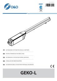
DIMENSIONI D’INGOMBRO • OVERALL DIMENSIONS •<br />
DIMENSIONS HORS-TOUT • ABMESSUNGEN •<br />
MEDIDAS<br />
SMART-<strong>400</strong><br />
AUTOMAZIONE PER CANCELLI SCORREVOLI 24V<br />
AUTOMATION FOR SLIDING GATES 24V<br />
AUTOMATION POUR PORTES COULISSANTES 24V<br />
AUTOMATION FÜR SCHIEBETORE 24V<br />
AUTOMACIÓN PARA CANCELAS CORREDERAS 24V<br />
AVANT-PROPOS<br />
Cette notice est destinée aux<br />
installateurs, aux utilisateurs et aux<br />
techniciens chargés de l’entretien.<br />
Lisez attentivement cette notice, avant<br />
d’installer l’automatisme, de l’utiliser<br />
et avant de procéder à son entretien<br />
ordinaire ou extraordinaire.<br />
Les opérations présentant des<br />
risques si elles ne sont pas effectuées<br />
correctement sont signalées avec les<br />
symboles :<br />
ELECTROCUTION ECRASEMENT<br />
La société O&O s.r.l. décline toute<br />
responsabilité en cas de dégâts à des<br />
personnes, animaux ou biens provoqués<br />
par des applications dépassant les<br />
limites prévues dans la fi che technique<br />
jointe ou par un usage différent de celui<br />
pour lequel l’automatisme a été conçu.<br />
GENERAL<strong>IT</strong>ES<br />
Le motoréducteur SMART-<strong>400</strong> 24Vdc<br />
a été conçu pour l’automation de portes<br />
coulissantes de <strong>400</strong> kg maximum dans le<br />
respect des normes européennes. Il est<br />
adapté à une utilisation de type résidentiel.<br />
EINLE<strong>IT</strong>UNG<br />
Das INSTALLATIONS-, BETRIEBS-<br />
UND WARTUNGSHANDBUCH ist<br />
für die Installateure, Anwender und<br />
Wartungsfachmänner bestimmt.<br />
Das Handbuch ist vor der Installation<br />
des Produkts sowie vor der ordentlichen<br />
und außerordentlichen Wartung sorgfältig<br />
zu lesen.<br />
Wenn die durch folgende Symbole<br />
gekennzeichneten Eingriffe nicht korrekt<br />
durchgeführt werden, kann es zu<br />
Gefahrsituationen kommen:<br />
STROMSCHLAG QUETSCHUNG<br />
Die Firma O&O s.r.l. haftet nicht für Personen-,<br />
Tier- oder Sachschäden, die auf eine<br />
unsachgemäße Anwendung des Produkts<br />
sowie auf das Überschreiten der im technischen<br />
Blatt angegebenen Grenzwerte<br />
zurückzuführen sind.<br />
ALLGEMEINES<br />
Der Getriebemotor SMART -<strong>400</strong> 24Vdc<br />
wurde für die Automation von Schiebetoren<br />
mit einem Gewicht bis zu <strong>400</strong> kg entwickelt,<br />
erfüllt die EU-Normen und ist für den Einsatz<br />
in Wohnanlagen geeignet.<br />
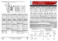
• Apertura a DESTRA<br />
• Opening on the RIGHT<br />
• Ouverture à DRO<strong>IT</strong>E<br />
• Öffnen nach RECHTS<br />
• Apertura a la DERECHA<br />
<strong>IT</strong> EN FR DE ES<br />
INTRODUCCIÓN<br />
El folleto de INSTALACIÓN, USO<br />
Y MANTENIMIENTO se destina a<br />
instaladores, usuarios y operadores de<br />
mantenimiento.<br />
Leer detenidamente el folleto antes de<br />
instalar el producto, utilizarlo y efectuar el<br />
mantenimiento ordinario o extraordinario.<br />
Las operaciones que, si no son<br />
efectuadas correctamente, pueden<br />
conllevar riesgos, vienen indicadas con<br />
los símbolos:<br />
ELECTROCUCIÓN APLASTAMIENTO<br />
La O&O s.r.l. no es responsable de<br />
daños causados a personas, animales o<br />
cosas, debidos a aplicaciones que superen<br />
los límites indicados en la fi cha técnica<br />
adjunta o debidos a utilización diferente<br />
de aquella apra la cual el producto fue<br />
proyectado.<br />
GENERALIDAD<br />
El motorreductor SMART-<strong>400</strong> 24Vcc ha<br />
sido específi camente pensado para mover<br />
cancelas correderas de hasta <strong>400</strong> kg de peso,<br />
en el respeto de las normativas europeas. Es<br />
apto para un uso de tipo residencial.<br />
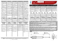
SCHEDA TECNICA - TECHNICAL DATA SHEET - FICHE TECHNIQUE - TECHNISCHES BLATT - FICHA TÉCNICA<br />
ALIMENTAZIONE • POWER • ALIMENTATION • STROMVERSORGUNG• ALIMENTACIÓN<br />
230Vac ± 10% 50/60 Hz<br />
MOTORE • MOTOR • MOTEUR • MOTOR • MOTOR<br />
24Vdc<br />
POTENZA ASSORB<strong>IT</strong>A • ABSORBED POWER • PUISSANCE ABSORBÉE • LEISTUNGSAUFNAHME • POTENCIA ABSORBIDA<br />
70W<br />
VELOC<strong>IT</strong>A • SPEED • V<strong>IT</strong>ESSE • GESCHWINDIGKE<strong>IT</strong> • VELOCIDAD<br />
12 m/min<br />
COPPIA • TORQUE • COUPLE • DREHMOMENT • PAR<br />
20Nm<br />
PESO MAX ANTA • MAX LEAF WEIGHT • POIDS MAXI VANTAIL • MAX GEW<strong>IT</strong>CH TORFLÜGEL • PESO MÁX HOJA<br />
<strong>400</strong> kg<br />
CENTRALINA • CONTROL UN<strong>IT</strong> • CENTRALE • STEUEREINHE<strong>IT</strong>• CENTRAL<strong>IT</strong>A<br />
LOG-SB<br />
SICUREZZA ALL’URTO • IMPACT SAFETY • SECUR<strong>IT</strong>E AU CHOC • STOSSSICHERHE<strong>IT</strong> • SEGURIDAD AL CHOQUE<br />
ENCODER<br />
CONDIZIONI AMBIENTALI • ENVIRONMENTAL COND<strong>IT</strong>IONS • COND<strong>IT</strong>IONS AMBIANTES • UMGEBUNGSBEDINGUNGEN • CONDICIONES AMBIENTALES -15 +40 °C<br />
GRADO DI PROTEZIONE • PROTECTION LEVEL • INDICE DE PROTECTION • SCHUTZGRAD • GRADO DE PROTECCIÓN IP 24<br />
300<br />
2<br />
DISPOSIZIONE • LAYOUT • DISPOS<strong>IT</strong>ION • DISPOS<strong>IT</strong>ION •<br />
DISPOSICIÓN<br />
O&O s.r.l. - Via Europa, 2 - 42015 CORREGGIO (R.E.) Italy<br />
tel. +39 (0)522 740111 - fax +39 (0)522 631290<br />
http://www.oeo.it - email: oeo@oeo.it<br />
Società soggetta ad attività di direzione e coordinamento di SOMFY S.A.<br />
Company subject to management and coordination activities by SOMFY S.A.<br />
190<br />
325<br />
• Apertura a SINISTRA<br />
• Opening on the LEFT<br />
• Ouverture à GAUCHE<br />
• Öffnen nach LINKS<br />
• Apertura a la IZQUIERDA
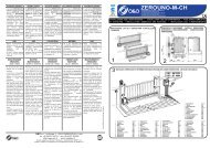
3 NOTA CAVI • CABLE NOTE • CONNEXION CABLE • BEMERKUNG ZU KABEL ANSCHLÜSSEN • NOTA CABLES<br />
1) Linea Monofase 2 x 1,5 + T<br />
2) Fotocellula Trasmettente 2 x 0,5<br />
3) Fotocellula Ricevente 4 x 0,5<br />
4) Lampeggiante 24V 2 x 0,5<br />
4) Antenna RG58 (4m)<br />
5) Selettore a chiave 3 x 0,5<br />
6) Battuta chiusura 2 x 0,5<br />
7) Battuta apertura 2 x 0,5<br />
1) Single-phase line 2 x 1,5 + T<br />
2) Transmitter photocell 2 x 0,5<br />
3) Receiver photocell 4 x 0,5<br />
4) Flashing light 24V 2 x 0,5<br />
4) Antenna RG58 (4m)<br />
5) Key selector 3 x 0,5<br />
6) Closing sensitive edge 2 x 0,5<br />
7) Opening sensitive edge 2 x 0,5<br />
1) Ligne monophasée 2 x 1,5 + T<br />
2) Photocellule émettrice 2 x 0,5<br />
3) Photocellule réceptrice 4 x 0,5<br />
4) Clignotant 24V 2 x 0,5<br />
4) Antenne RG58 (4m)<br />
5) Sélecteur à clé 3 x 0,5<br />
6) Capteur fermeture 2 x 0,5<br />
7) Capteur ouverture 2 x 0,5<br />
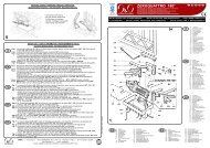
4<br />
• Fissare la piastra di base con tasselli ad espansione oppure<br />
annegare le zanche nel calcestruzzo.<br />
• Secure the base plate with expansion bolts or embed the fi shtail<br />
clamps in concrete.<br />
• Fixer la plaque de base à l’aide de chevilles à expansion ou enfouir<br />
les agrafes dans le béton.<br />
• Die Grundplatte mit Dübeln befestigen oder die Verankerungsklauen<br />
in Beton eingießen.<br />
• Fijar la placa de fundación con tornillos de expansión o bien<br />
introducir las grapas de anclaje en el hormigón.<br />
5<br />
BASAMENTO • BASE • BASE • BASIS • BASE<br />
1<br />
3<br />
7<br />
1) Einphasenleitung 2 x 1,5 + T<br />
2) Senderfotozelle 2 x 0,5<br />
3) Empfängerfotozelle 4 x 0,5<br />
4) Blinkleuchte 24V 2 x 0,5<br />
4) Antenne RG58 (4m)<br />
5) Schlüsselschalter 3 x 0,5<br />
6) Anschlag beim Schließen 2 x 0,5<br />
7) Anschlag beim Öffnen 2 x 0,5<br />
MONTAGGIO • ASSEMBLY • MONTAGE • MONTAGE • MONTAJE<br />
25<br />
160<br />
75<br />
1) Línea monofásica 2 x 1,5 + T<br />
2) Fotocélula transmisor 2 x 0,5<br />
3) Fotocélula receptor 4 x 0,5<br />
4) Indicador intermitente 24V 2 x 0,5<br />
4) Antena RG58 (4m)<br />
5) Selector de llave 3 x 0,5<br />
6) Disp. sensible a la presión 2 x 0,5<br />
7) Tope de abertura 2 x 0,5<br />
330<br />
2<br />
6<br />
4<br />
5<br />
14<br />
76<br />
6<br />
7<br />
8<br />
MONTARE LA CREMAGLIERA • MOUNT THE RACK • MONTEZ LA CREMAILLERE • MONTAGE DER ZAHNSTANGE<br />
MONTAR LA CREMALLERA<br />
100<br />
76<br />
25<br />
MANOVRA MANUALE • MANUAL MANOEUVRE • MANOEUVRE MANUELLE • MANUELLES MANÖVRIEREN<br />
MANIOBRA MANUAL<br />
• Prima di effettuare qualsiasi intervento sull’impianto<br />
togliere l’alimentazione elettrica.<br />
• Always disconnect the electricity before attempting any<br />
work on the system.<br />
• Coupez l’arrivée de courant électrique avant toute<br />
intervention sur l’automatisme.<br />
• Vor jeglichen Eingriffen an der Anlage ist die<br />
Stromversorgung zu unterbrechen.<br />
• Antes de cualquier operación en la instalación, cortar<br />
la alimentación eléctrica.<br />
• Accoppiamento pignone-cremagliera (modulo 4)<br />
• Rack-to-pinion coupling (module 4)<br />
• Assemblage pignon-crémalière (module 4)<br />
• Zwischen Zahnstange und dem Antriebsritzel (Ritzelmodul 4)<br />
• Acoplamento piñon-cremaliera (módulo 4)<br />
1 ÷ 2 mm<br />
• Allineamento cremagliera<br />
• Rack alignment<br />
• Alignement crémaillère<br />
• Fluchtung der Zahnstange<br />
• Alineación de la cremallera<br />
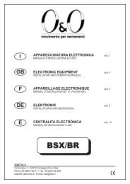
MONTAGGIO ARRESTI MECCANICI • INSTALL MECHANICAL STOPS ASSEMBLY • MONTAGE DES BUTÉES MÉCANIQUES •<br />
MONTAGE DER MECHANISCHEN SPERREN • MONTAJE DE LOS TOPES MECÁNICOS<br />
Installare sulla guida di scorrimento a terra gli arresti meccanici di fi necorsa<br />
opportunamente dimensionati alla massa del cancello. Gli arresti meccanici<br />
servono come riferimento di fi necorsa per le manovre di apertura e di<br />
chiusura.<br />
Install the mechanical end of travel stops on the sliding guides on the<br />
ground. Their size must be suitable for the gate’s weight. The mechanical<br />
stops act as an end of travel reference for the opening and closing manoeuvres.<br />
Installez les butées mécaniques de fi n de course correctement dimensionnées<br />
en fonction du poids de la porte sur le guide de coulissement au sol.<br />
Les butées mécaniques servent de point de fi n de course pour l’ouverture<br />
et la fermeture.<br />
90°<br />
An den Bodenführungsschienen die für das Gewicht des Tors geeigneten<br />
mechanischen Endanschlagsperren installieren. Die mechanischen Sperren<br />
dienen als Endanschlag beim Öffnen und Schließen des Tors.<br />
Instalar en la guía de deslizamiento en el suelo los topes mecánicos de<br />
fi nal de carrera oportunamente dimensionados para la masa de la cancela.<br />
Los topes mecánicos sirven de referencia de fi nal de carrera para las<br />
maniobras de apertura y de cierre.<br />
9<br />
COLLEGAMENTI ELETTRICI • ELECTRICAL CONNECTIONS • BRANCHEMENTS ELECTRIQUES •<br />
ELEKTRISCHE ANSCHLÜSSE • CONEXIONES ELÉCTRICAS<br />
• Regolazione orizzontale e fi ssaggio<br />
• Horizontal adjustement unit and anchorage<br />
• Réglage orizontal et fi xation<br />
• Horizontale Einstellung<br />
• Regulación horizontal y fi jación<br />
• Regolazione verticale o messa in bolla<br />
• Vertical adjustement and unit leveling<br />
• Réglage vertical ou mise à niveau<br />
• Vertikale Einstellung<br />
• Regulación vertical y nivelación<br />
• Consultare il manuale d’installazione e uso della centralina LOG-SB<br />
• Consult the LOG-SB control unit’s installation and operating manual<br />
• Consulter le manuel d’installation et d’utilisation de la centrale LOG-SB<br />
• Die Installations und Bedienungsanleitungen der Steuereinheit LOG-SB nachschlagen.<br />
• Consultar el manual de instalación y uso de la centralita LOG-SB