


Sezioni d'entrata Inlet sections Disegni in sezione Sections Schemi ...
Sezioni d'entrata Inlet sections Disegni in sezione Sections Schemi ...
Sezioni d'entrata Inlet sections Disegni in sezione Sections Schemi ...

Create successful ePaper yourself
Turn your PDF publications into a flip-book with our unique Google optimized e-Paper software.
<strong>Sezioni</strong> d’entrata<br />
<strong>Inlet</strong> <strong>sections</strong><br />
<strong>Disegni</strong> <strong>in</strong> <strong>sezione</strong><br />
<strong>Sections</strong><br />
<strong>Schemi</strong> idraulici funzionamento<br />
Hydraulic diagrams<br />
Dimensioni d’<strong>in</strong>gombro HPV41<br />
HPV41 Overall dimensions<br />
Caratteristiche idrauliche<br />
Hydraulic features<br />
Curve caratteristiche<br />
Characteristic curves<br />
Moduli e codici d’ord<strong>in</strong>azione HPV41<br />
HPV41 Modules and order<strong>in</strong>g codes<br />
Moduli certificati secondo direttiva ATEX<br />
Modules <strong>in</strong> accordance with the ATEX directive<br />
Tavola di selezione moduli<br />
Modules selection chart<br />
Modulo di ord<strong>in</strong>azione HPV41<br />
HPV41 Order form<br />
Pagg. 1 ÷ 3<br />
Pages 1 ÷ 3<br />
Pag. 4<br />
Page 4<br />
Pag. 5<br />
Page 5<br />
Pag. 10<br />
Page 10<br />
Pag. 15<br />
Page 15<br />
Pagg. 16, 17<br />
Pages 16, 17<br />
Pagg. 18 ÷90<br />
Pages 18 ÷90<br />
Pagg. 95 ÷ 122<br />
Pages 95 ÷ 122<br />
Pagg. 124 ÷131<br />
Pages 124 ÷131<br />
Pagg. 132, 133<br />
Pages 132, 133
Sezione di entrata HPV 41, standard<br />
Standard HPV 41 <strong>in</strong>let section<br />
1<br />
2<br />
3<br />
L P<br />
Regolatore di portata a 3 vie<br />
3 way flow regulator<br />
Valvola di massima pressione<br />
Pilot pressure relief valve<br />
Valvola riduttrice di pressione<br />
Pressure reduction valve<br />
Connessione bassa pressione<br />
Low pressure port, 19 ÷ 22 bar<br />
Sono suddivise <strong>in</strong> due versioni:<br />
- centro aperto per l’impiego con pompe <strong>in</strong> cil<strong>in</strong>drata fissa<br />
- centro chiuso per l’impiego con pompe load-sens<strong>in</strong>g<br />
Nelle versioni <strong>in</strong> centro aperto il regolatore di portata/pressione pos.1<br />
durante le fasi di non lavoro del distributore, provvede a scaricare <strong>in</strong> T<br />
l’<strong>in</strong>tera portata della pompa (vedi curve caratteristiche).<br />
Diversamente, nelle fasi di lavoro consentirà l'alimentazione<br />
all'elemento o agli elementi comandati, adeguandosi istantaneamente<br />
alla effettiva portata richiesta dagli utilizzi e scaricando al serbatoio<br />
l'eventuale portata <strong>in</strong> eccesso alla pressione più elevata operante <strong>in</strong><br />
quel momento.<br />
Cambiando due semplici pilotaggi <strong>in</strong>terni la <strong>sezione</strong> si trasforma <strong>in</strong><br />
centro chiuso. Nelle versioni <strong>in</strong> centro chiuso il regolatore pos. 1<br />
mantiene solo la funzione di regolatore di pressione, diventando il<br />
primo stadio della valvola di max pressione generale pos.2, la cui<br />
taratura deve essere di circa 30 bar superiore alla massima pressione di<br />
lavoro.<br />
Entrambe le versioni possono essere fornite con la valvola riduttrice di<br />
pressione pos.3 che provvede a creare una l<strong>in</strong>ea di bassa pressione (18-<br />
22 bar) che alimenta i moduli elettroidraulici MHPED o anche gli<br />
stessi manipolatori idraulici.<br />
Ovviamente nel caso che il distributore abbia solo il comando<br />
manuale, la valvola riduttrice di pressione non é necessaria.<br />
They are divided <strong>in</strong>to two versions:<br />
- open centre for use with fixed displacement pumps<br />
- closed centre for use with load-sens<strong>in</strong>g pumps.<br />
In the open centre versions, when the spool is not work<strong>in</strong>g, the flow/<br />
pressure regulator -pos. 1- unloads to T the entire pump flow (see<br />
characteristic curves).<br />
Otherwise, when the spool is work<strong>in</strong>g, it will feed the controlled<br />
element or elements, adapt<strong>in</strong>g <strong>in</strong>stantaneously to the actual flow<br />
required by the ports and unload<strong>in</strong>g any excess flow at the highest<br />
pressure of that moment to the tank.<br />
By chang<strong>in</strong>g two <strong>in</strong>ternal pilot l<strong>in</strong>es, the section is converted <strong>in</strong>to a<br />
closed centre version. In the closed centre versions, the regulator -pos.<br />
1- only ma<strong>in</strong>ta<strong>in</strong>s the pressure regulator function, becom<strong>in</strong>g the first<br />
stage of the ma<strong>in</strong> pressure relief valve pos. 2, which must be calibrated<br />
to about 30 bar more than the maximum work pressure.<br />
Both versions can be supplied with the pressure reduction valve -pos.<br />
3- where orig<strong>in</strong>ates a low pressure l<strong>in</strong>e (20 bar) that feeds the<br />
MHPED electrohydraulic modules or also the same hydraulic<br />
manipulators. Obviously, if the valve is only equipped with manual<br />
control, the pressure reduction valve is not required.<br />
IE/HPV41/002/2007 HPV41 - 1
HSE, <strong>sezione</strong> di entrata HPV 41 con elettrovalvola di messa a scarico segnale LS<br />
(HSEV)<br />
HSE, standard HPV 41 <strong>in</strong>let section with solenoid LS unload<strong>in</strong>g valve (HSEV)<br />
1<br />
2<br />
3<br />
4<br />
L P<br />
Regolatore di portata a 3 vie<br />
3 way flow regulator<br />
Valvola di massima pressione<br />
Pilot pressure relief valve<br />
Valvola riduttrice di pressione<br />
Pressure reduction valve<br />
Elettrovalvola di messa a scarico<br />
segnale LS<br />
Solenoid LS unload<strong>in</strong>g valve<br />
Connessione bassa pressione<br />
Low pressure port, 18 ÷ 22 bar<br />
Tutte le versioni possono essere fornite di elettrovalvola di messa a<br />
scarico del segnale LS (pos. 4). L’elettrovalvola può essere<br />
normalmente aperta o normalmente chiusa. Il suo <strong>in</strong>tervento nelle fasi<br />
di lavoro provoca la messa a scarico immediata del segnale load<br />
sens<strong>in</strong>g e il conseguente arresto di ogni movimento degli attuatori.<br />
Nelle versioni <strong>in</strong> centro aperto, il valore della pressione di messa a<br />
scarico della pompa é uguale alla somma della contropressione agente<br />
sulla l<strong>in</strong>ea T più la pressione necessaria per l’apertura del regolatore<br />
portata/pressione (pos. 1) per consentire il collegamento P <strong>in</strong> T (quasi<br />
sempre compresa tra 8 e 15 bar).<br />
Nelle versioni <strong>in</strong> centro chiuso, la messa a scarico del segnale LS<br />
provoca l’abbassamento della pressione sull’attacco P ad un valore<br />
uguale alla pressione di stand-by alla quale la pompa è regolata.<br />
Utilizzando l’elettrovalvola di messa a scarico del segnale LS su<br />
sezioni d’entrata sia <strong>in</strong> centro aperto che <strong>in</strong> centro chiuso, Aron<br />
raccomanda particolare attenzione a quei movimenti la cui pressione di<br />
lavoro sia <strong>in</strong>feriore alla pressione di vent<strong>in</strong>g (centro aperto) o alla<br />
pressione di stand-by della pompa (centro chiuso) perché potrebbero<br />
comunque muoversi.<br />
All versions can be supplied with an LS signal unload<strong>in</strong>g solenoid<br />
valve - pos. 4. The solenoid valve can be normally open or normally<br />
closed. If it is activated dur<strong>in</strong>g the work phases it immediately unloads<br />
the load sens<strong>in</strong>g signal and subsequently stops all movements of the<br />
actuators.<br />
In the open centre versions, the pump unload<strong>in</strong>g pressure value is<br />
equal to the sum of the counterpressure act<strong>in</strong>g on the T l<strong>in</strong>e plus the<br />
pressure required to open the flow/pressure regulator -pos. 1- to<br />
connect P to T (often from 8 to 15 bar).<br />
In the closed centre versions, unload<strong>in</strong>g the LS signal lowers the<br />
pressure <strong>in</strong> P at a value equal to the stand-by pressure at which the<br />
pump is regulated.<br />
Us<strong>in</strong>g the solenoid LS unload<strong>in</strong>g valve on the <strong>in</strong>let <strong>sections</strong> <strong>in</strong> the open<br />
and closed centre versions, Aron urge grate care <strong>in</strong> this method,<br />
because all functions requir<strong>in</strong>g a lower work<strong>in</strong>g pressure, might be<br />
operated.<br />
IE/HPV41/002/2007 HPV41 - 2
HSE, <strong>sezione</strong> di entrata HPV 41 con valvola di messa a scarico pompa (HSER)<br />
HSE, standard HPV 41 <strong>in</strong>let section with pump unload<strong>in</strong>g valve function (HSER)<br />
1<br />
5<br />
L P<br />
Regolatore di portata a 3 vie<br />
3 way flow regulator<br />
Elemento logico a cartuccia HSER<br />
Cartridge logic element, HSER<br />
Connessione bassa pressione<br />
Low pressure port, 18 ÷ 22 bar<br />
Sia nelle versione <strong>in</strong> centro aperto che <strong>in</strong> centro chiuso, è possibile<br />
montare un elemento logico a cartuccia pilotabile a distanza (pos. 5)<br />
per la messa a scarico rapida della pompa, bypassando il regolatore di<br />
portata/ pressione (pos. 1).<br />
In questa configurazione il valore della pressione di messa a scarico<br />
della pompa è uguale alla somma della contropressione agente sulla<br />
l<strong>in</strong>ea T, più la pressione necessaria per l’apertura della valvola HSER<br />
(0.6 bar) per consentire il collegamento P <strong>in</strong> T.<br />
Con questa soluzione il p per la messa a scarico della pompa risulta<br />
essere molto più basso di quello che si formerebbe <strong>in</strong>vece utilizzando<br />
l'elettrvalvola di messa a scarico del segnale LS (vedi curve<br />
caratteristiche).<br />
In the open and closed centre versions, it is possible to mount a<br />
remote-controlled cartridge logic element (pos. 5) for rapid pump<br />
unload<strong>in</strong>g, thus by-pass<strong>in</strong>g the flow/pressure regulator (pos. 1).<br />
In this configuration, the pump unload<strong>in</strong>g pressure value is equal to<br />
the sum of the counterpressure act<strong>in</strong>g on the T l<strong>in</strong>e, plus the pressure<br />
required to open the HSER valve (0.6 bar) to connect P with T.<br />
With this solution the p for pump unload<strong>in</strong>g is much lower than what<br />
would be created <strong>in</strong>stead us<strong>in</strong>g the LS signal unload<strong>in</strong>g solenoid valve<br />
(see characteristic curves).<br />
IE/HPV41/002/2007 HPV41 - 3
<strong>Sezioni</strong> HPV 41, <strong>sezione</strong> di entrata per sistema <strong>in</strong> centro aperto<br />
HPV 41 sectional draw<strong>in</strong>gs, <strong>in</strong>let section for open centre system<br />
1. REGOLATORE<br />
PORTATA/PRESSIONE<br />
2. FILTRO LINEA BASSA PRESSIONE<br />
3. VALVOLA DI MASSIMA<br />
PRESSIONE GENERALE<br />
4. CONNESSIONE MANOMETRICA<br />
PRESSIONE POMPA<br />
5. ELETTROVALVOLA PER MESSA A<br />
SCARICO SEGNALE LS<br />
6. VALVOLA RIDUTTRICE DI<br />
PRESSIONE<br />
7. FILTRO LINEA LOAD SENSING<br />
8. VALVOLA DI MAX LINEA BASSA<br />
PRESSIONE<br />
9. VALVOLA ANTISHOCK E<br />
ANTICAVITAZIONE<br />
10. VALVOLA DI MAX PRESSIONE LS<br />
11. COMPENSATORE DI PRESSIONE<br />
12. VALVOLA DI SCAMBIO<br />
13. ELETTROVALVOLA DI MESSA A<br />
SCARICO DEL SEGNALE LS B<br />
14. ELETTROVALVOLA DI MESSA A<br />
SCARICO DEL SEGNALE LS A<br />
15. ASTA DI DISTRIBUZIONE<br />
16. REGISTRO PER REGOLAZIONE<br />
FINE, PORTATA UTILIZZO A<br />
17. REGISTRO PER REGOLAZIONE<br />
FINE, PORTATA UTILIZZO B<br />
18. CAPPELLOTTO PER CINEMATISMO<br />
COMANDO MANUALE<br />
19. CONNESSIONE PILOTA,<br />
PRESSIONE LS B<br />
20. CONNESSIONE PILOTA,<br />
PRESSIONE LS A<br />
21. CONNESSIONE PILOTA VALVOLA<br />
DI MESSA A SCARICO POMPA<br />
1. FLOW/PRESSURE REGULATOR<br />
2. LOW PRESSURE LINE FILTER<br />
3. MAIN PRESSURE RELIEF VALVE<br />
4. PUMP PRESSURE GAUGE PORT<br />
5. PUMP UNLOADING VALVE<br />
6. PRESSURE REDUCTION VALVE<br />
7. LOAD SENSING LINE FILTER<br />
8. LOW PRESSURE LINE RELIEF VALVE<br />
9. SHOCK AND SUCTION VALVE<br />
10. LS PRESSURE RELIEF VALVE<br />
11. PRESSURE COMPENSATOR<br />
12. EXCHANGE VALVE<br />
13. LS B SIGNAL UNLOADING SOLENOID<br />
VALVE<br />
14. LS A SIGNAL UNLOADING SOLENOID<br />
VALVE<br />
15. SPOOL<br />
16. PORT A FLOW FINE ADJUSTMENT<br />
REGISTER<br />
17. PORT B FLOW FINE ADJUSTMENT<br />
REGISTER<br />
18. COVER FOR MANUAL CONTROL<br />
KINEMATIC MOTION<br />
19. LS B PRESSURE PILOT LINE PORT<br />
20. LS A PRESSURE PILOT LINE PORT<br />
21. MHPE MODULE UNLOADING LINE<br />
PORT<br />
22. LOW PRESSURE PILOT LINE PORT<br />
23. PILOT LINE, PUMP UNLOADING<br />
VALVE<br />
IE/HPV41/002/2007 HPV41 - 4
Schema idraulico HPV 41 per sistema <strong>in</strong> centro aperto<br />
HPV 41 hydraulic diagram for open centre system<br />
1.REGOLATORE PORTATA/PRESSIONE<br />
2.FILTRO LINEA BASSA PRESSIONE<br />
3.VALVOLA DI MASSIMA PRESSIONE GENERALE<br />
4.CONNESSIONE MANOMETRICA PRESSIONE<br />
POMPA<br />
5.ELETTROVALVOLA PILOTA PER MESSA A<br />
SCARICO POMPA<br />
6.VALV. RIDUTTRICE DI PRESSIONE<br />
7.FILTRO LINEA LOAD SENSING<br />
8.VALVOLA DI MASSIMA LINEA BASSA PRESSIONE<br />
9.VALVOLA ANTISHOCK E ANTICAVITAZIONE<br />
10.VALVOLA DI MASSIMA PRESSIONE LS<br />
11.COMPENSATORE DI PRESSIONE<br />
12.VALVOLA DI SCAMBIO<br />
13.ELETTROVALVOLA DI MESSA A SCARICO DEL<br />
SEGNALE LS B<br />
14.ELETTROVALVOLA DI MESSA A SCARICO DEL<br />
SEGNALE LS A<br />
15.ASTA DI DISTRIBUZIONE<br />
16.REGISTRO PER REGOLAZIONE FINE PORTATA<br />
UTILIZZO A<br />
17.REGISTRO PER REGOLAZIONE FINE PORTATA<br />
UTILIZZO B<br />
18.CAPPELLOTTO PER CINEMATISMO COMANDO<br />
MANUALE<br />
19.CONNESSIONE PILOTA PRESSIONE LS B<br />
20.CONNESSIONE PILOTA PRESSIONE LS A<br />
21.DRENAGGIO PER MODULI ELETTRICI<br />
22.CONNESSIONE PILOTA LINEA BASSA PRESSIONE<br />
23.CONNESSIONE PILOTA VALVOLA DI MESSA A<br />
SCARICO POMPA<br />
1.FLOW/PRESSURE REGULATOR<br />
2.LOW PRESSURE LINE FILTER<br />
3.MAIN PRESSURE RELIEF VALVE<br />
4.PUMP PRESSURE GAUGE PORT<br />
5.PUMP UNLOADING VALVE<br />
6.PRESSURE REDUCTION VALVE<br />
7.LOAD SENSING LINE FILTER<br />
8.LOW PRESSURE LINE RELIEF VALVE<br />
9.SHOCK AND SUCTION VALVE<br />
10.LS PRESSURE RELIEF VALVE<br />
11.PRESSURE COMPENSATOR<br />
12.EXCHANGE VALVE<br />
13.LS B SIGNAL UNLOADING SOLENOID VALVE<br />
14.LS A SIGNAL UNLOADING SOLENOID VALVE<br />
15.SPOOL<br />
16.PORT A FLOW FINE ADJUSTMENT REGISTER<br />
17.PORT B FLOW FINE ADJUSTMENT REGISTER<br />
18.COVER FOR MANUAL CONTROL KINEMATIC<br />
MOTION<br />
19.LS B PRESSURE PILOT LINE PORT<br />
20.LS A PRESSURE PILOT LINE PORT<br />
21.ELECTROHYDRAULIC CONTROLS DRAIN LINE<br />
22.LOW PRESSURE PILOT LINE PORT<br />
23.PILOT LINE, PUMP UNLOADING VALVE<br />
IE/HPV41/002/2007 HPV41 - 5
Descrizione del gruppo HPV 41 con <strong>sezione</strong> di entrata HSE <strong>in</strong> centro aperto<br />
Function - HPV 41 valve group with HSE open centre <strong>in</strong>let section<br />
Con le aste di distribuzione 15 <strong>in</strong> posizione centrale, la l<strong>in</strong>ea<br />
LS, la camera lato molla del regolatore di portata/pressione (1),<br />
la camera lato molla del compensatore di pressione (11) sono<br />
collegate con lo scarico (T) consentendo alla portata della<br />
pompa di defluire al serbatoio attraverso il regolatore di<br />
portata/pressione (1).<br />
La portata della pompa, il carico della molla del regolatore di<br />
portata/pressione (1), e la contropressione agente sulla l<strong>in</strong>ea di<br />
scarico (T), determ<strong>in</strong>ano la pressione di libera circolazione<br />
della pompa. (Vedi curve caratteristiche).<br />
Quando l’asta di distribuzione (15) viene azionata, l’utilizzo<br />
selezionato viene messo <strong>in</strong> comunicazione con la l<strong>in</strong>ea P1 e la<br />
pressione di lavoro tramite la l<strong>in</strong>ea LS, viene <strong>in</strong>viata sul<br />
regolatore di portata/pressione (1).<br />
La portata ottenuta sarà esclusivamente <strong>in</strong> funzione dell’area di<br />
attraversamento dell’asta, e del relativo p che si formerà<br />
lungo il campo di regolazione della stessa.<br />
Qualora vengano azionate due o più aste contemporaneamente<br />
operanti a pressioni diverse, i compensatori di pressione (11)<br />
manterranno costante la caduta di pressione (p) e<br />
conseguentemente costante sarà la portata sulle aste (15) entro<br />
il campo di portata massima della pompa.<br />
Diversamente se vengono azionate due o più aste<br />
contemporaneamente di elementi senza compensatori di<br />
pressione, la portata sulle aste non sarà costante ma funzione<br />
delle pressioni di lavoro.<br />
Le valvole di massima pressione Load Sens<strong>in</strong>g (10),<br />
utilizzando una piccola portata pilota, limitano con precisione<br />
la pressione agli utilizzi A/ B senza spreco di energia,<br />
diversamente dalle valvole antishock che, scaricando anche<br />
l'<strong>in</strong>tera portata delle aste, sono molto dissipative.<br />
Le elettrovalvole on-of (13 - 14) che <strong>in</strong>tercettano le l<strong>in</strong>ee pilota<br />
LsA e LsB, se attivate annullano istantaneamente la portata sul<br />
relativo utilizzo <strong>in</strong>teressato.<br />
La valvola riduttrice di pressione (6) fornisce una l<strong>in</strong>ea di<br />
bassa pressione (18-22 bar), che alimenta dall’<strong>in</strong>terno i moduli<br />
elettroidraulici MHPED, e dall’esterno tramite la connessione<br />
(22) i manipolatori idraulici.<br />
Le connessioni pilota LsA e LsB consentono di controllare a<br />
distanza le pressioni di lavoro max degli utilizzi A/B di ogni<br />
elemento.<br />
With the spools 15 <strong>in</strong> the central position, the LS l<strong>in</strong>e, the<br />
chamber on the spr<strong>in</strong>g side of the flow/pressure regulator (1)<br />
and the chamber on the spr<strong>in</strong>g side of the pressure<br />
compensator (11) are connected with the exhaust core (T),<br />
allow<strong>in</strong>g the pump flow to be conveyed to the tank through the<br />
flow/ pressure regulator (1).<br />
The pump flow, the spr<strong>in</strong>g load of the flow/pressure regulator<br />
(1) and the counterpressure act<strong>in</strong>g on the exhaust l<strong>in</strong>e (T),<br />
determ<strong>in</strong>e the pump free circulation pressure (See<br />
characteristic curves).<br />
When the spool (15) is activated, the port selected is placed <strong>in</strong><br />
communication with l<strong>in</strong>e P1 and the work pressure through<br />
l<strong>in</strong>e Ls is sent to the flow/pressure regulator (1).<br />
The flow obta<strong>in</strong>ed will only depend on the cross<strong>in</strong>g area of the<br />
spool and the relative p that will be created along the spool<br />
adjustment range.<br />
If two or more spools operat<strong>in</strong>g at different pressure values<br />
are activated at the same time, the pressure compensators (11)<br />
will keep the pressure drop constant (p) and thus the flow on<br />
the spools (15) will be constant with<strong>in</strong> the maximum pump flow<br />
range.<br />
On the other hand, if two or more spools of elements without<br />
pressure compensators are activated simultaneously, the flow<br />
on the spools will not be constant but will vary accord<strong>in</strong>g to<br />
the work pressures.<br />
The Load Sens<strong>in</strong>g pressure relief valves (10), us<strong>in</strong>g a small<br />
pilot l<strong>in</strong>e flow, precisely limit the pressure at ports A/B without<br />
wast<strong>in</strong>g energy, unlike the anti-shock valve which also when<br />
unload<strong>in</strong>g the entire flow of the spools, are very wasteful.<br />
The on-off solenoid valves (13-14) which cut off the LsA and<br />
LsB pilot l<strong>in</strong>es, if activated, <strong>in</strong>stantaneously cancel the flow on<br />
the relative port.<br />
The pressure reduction valve (6) supplies a low pressure l<strong>in</strong>e<br />
(18-22 bar) which <strong>in</strong>ternally feeds the MHPE electrohydraulic<br />
modules and, externally, the hydraulic manipulators through<br />
the port 22.<br />
The max. work pressures of ports A/B of each element can be<br />
remote controlled us<strong>in</strong>g the LsA and LsB pilot l<strong>in</strong>e ports.<br />
IE/HPV41/002/2007 HPV41 - 6
<strong>Sezioni</strong> HPV 41, <strong>sezione</strong> di entrata per sistema <strong>in</strong> centro chiuso<br />
HPV 41 sectional draw<strong>in</strong>gs, <strong>in</strong>let section for closed centre system<br />
1.REGOLATORE PORTATA/PRESSIONE<br />
2.FILTRO LINEA BASSA PRESSIONE<br />
3.VALVOLA DI MASSIMA PRESSIONE<br />
GENERALE<br />
4.CONNESSIONE MANOMETRICA<br />
PRESSIONE POMPA<br />
5.ELETTROVALVOLA PER MESSA A<br />
SCARICO SEGNALE LS<br />
6.VALVOLA RIDUTTRICE DI<br />
PRESSIONE<br />
7.FILTRO LINEA LOAD SENSING<br />
8.VALVOLA DI MAX LINEA BASSA<br />
PRESSIONE<br />
9.VALVOLA ANTISHOCK E<br />
ANTICAVITAZIONE<br />
10.VALVOLA DI MAX PRESSIONE LS<br />
11.COMPENSATORE DI PRESSIONE<br />
12.VALVOLA DI SCAMBIO<br />
13.ELETTROVALVOLA DI MESSA A<br />
SCARICO DEL SEGNALE LS B<br />
14.ELETTROVALVOLA DI MESSA A<br />
SCARICO DEL SEGNALE LS A<br />
15.ASTA DI DISTRIBUZIONE<br />
16.REGISTRO PER REGOLAZIONE FINE,<br />
PORTATA UTILIZZO A<br />
17.REGISTRO PER REGOLAZIONE FINE,<br />
PORTATA UTILIZZO B<br />
18.CAPPELLOTTO PER CINEMATISMO<br />
COMANDO MANUALE<br />
19.CONNESSIONE PILOTA, PRESSIONE<br />
LS B<br />
20.CONNESSIONE PILOTA, PRESSIONE<br />
LS A<br />
21.CONNESSIONE PILOTA VALVOLA DI<br />
MESSA A SCARICO POMPA<br />
1.FLOW/PRESSURE REGULATOR<br />
2.LOW PRESSURE LINE FILTER<br />
3.MAIN PRESSURE RELIEF VALVE<br />
4.PUMP PRESSURE GAUGE PORT<br />
5.PUMP UNLOADING VALVE<br />
6.PRESSURE REDUCTION VALVE<br />
7.LOAD SENSING LINE FILTER<br />
8.LOW PRESSURE LINE RELIEF VALVE<br />
9.SHOCK AND SUCTION VALVE<br />
10.LS PRESSURE RELIEF VALVE<br />
11.PRESSURE COMPENSATOR<br />
12.EXCHANGE VALVE<br />
13.LS B SIGNAL UNLOADING SOLENOID<br />
VALVE<br />
14.LS A SIGNAL UNLOADING SOLENOID<br />
VALVE<br />
15.SPOOL<br />
16.A PORT FLOW FINE ADJUSTMENT<br />
REGISTER<br />
17.B PORT FLOW FINE ADJUSTMENT<br />
REGISTER<br />
18.COVER FOR MANUAL CONTROL<br />
KINEMATIC MOTION<br />
19.LS B PRESSURE PILOT LINE PORT<br />
20.LS A PRESSURE PILOT LINE PORT<br />
21.MHPE MODULE UNLOADING LINE<br />
PORT<br />
22.LOW PRESSURE PILOT LINE PORT<br />
23.PILOT LINE, PUMP UNLOADING VALVE<br />
IE/HPV41/002/2007 HPV41 - 7
Schema idraulico HPV 41 per sistema <strong>in</strong> centro chiuso<br />
HPV 41 hydraulic diagram for closed centre system<br />
1. PRIMO STADIO REGOLATORE DI PRESSIONE<br />
2. FILTRO LINEA BASSA PRESSIONE<br />
3. SECONDO STADIO PILOTA REGOLATORE DI<br />
PRESSIONE<br />
4. CONNESSIONE MANOMETRICA PRESSIONE<br />
POMPA<br />
5. ELETTROVALVOLA PER MESSA A SCARICO DEL<br />
SEGNALE LS<br />
6. VALVOLA RIDUTTRICE DI PRESSIONE<br />
7. FILTRO LINEA LOAD SENSING<br />
8. VALVOLA DI MASSIMA LINEA BASSA PRESSIONE<br />
9. VALVOLA ANTISHOCK E ANTICAVITAZIONE<br />
10. VALVOLA DI MASSIMA PRESSIONE LS<br />
11. COMPENSATORE DI PRESSIONE<br />
12. VALVOLA DI SCAMBIO<br />
13. ELETTROVALVOLA DI MESSA A SCARICO DEL<br />
SEGNALE LsB<br />
14. ELETTROVALVOLA DI MESSA A SCARICO DEL<br />
SEGNALE LsA<br />
15. ASTA DI DISTRIBUZIONE<br />
16. REGISTRO PER REGOLAZIONE FINE PORTATA<br />
UTILIZZO A<br />
17. REGISTRO PER REGOLAZIONE FINE PORTATA<br />
UTILIZZO B<br />
18. CAPPELLOTTO PER CINEMATISMO COMANDO<br />
MANUALE<br />
19. CONNESSIONE PILOTA PRESSIONE LsB<br />
20. CONNESSIONE PILOTA PRESSIONE LsA<br />
21. DRENAGGIO PER MODULI ELETTRICI<br />
22. CONNESSIONE PILOTA LINEA BASSA PRESSIONE<br />
23. REGOLATORE PORTATA/PRESSIONE POMPA<br />
1. PRESSURE REGULATOR FIRST STAGE<br />
2. LOW PRESSURE LINE FILTER<br />
3. PRESSURE REGULATOR PILOT LINE SECOND<br />
STAGE<br />
4. PUMP PRESSURE GAUGE PORT<br />
5. LS SIGNAL UNLOADING SOLENOID VALVE<br />
6. PRESSURE REDUCTION VALVE<br />
7. LOAD SENSING LINE FILTER<br />
8. LOW PRESSURE LINE RELIEF VALVE<br />
9. SHOCK AND SUCTIONVALVE<br />
10. LS PRESSURE RELIEF VALVE<br />
11. PRESSURE COMPENSATOR<br />
12. EXCHANGE VALVE<br />
13. LsB SIGNAL UNLOADING SOLENOID VALVE<br />
14. LsA SIGNAL UNLOADING SOLENOID VALVE<br />
15. SPOOL<br />
16. PORT A FLOW FINE ADJUSTER<br />
17. PORT B FLOW FINE ADJUSTER<br />
18. COVER FOR MANUAL CONTROL KINEMATIC<br />
MOTION<br />
19. LsB PRESSURE PILOT LINE PORT<br />
20. LsA PRESSURE PILOT LINE PORT<br />
21. ELECTROHYDRAULIC CONTROLS DRAIN LINE<br />
22. LOW PRESSURE PILOT LINE PORT<br />
23. PUMP FLOW/PRESSURE REGULATOR<br />
IE/HPV41/002/2007 HPV41 - 8
Descrizione del gruppo HPV 41 con <strong>sezione</strong> di entrata HSE <strong>in</strong> centro chiuso<br />
Function - HPV 41 valve group with HSE closed centre <strong>in</strong>let section<br />
Con le aste di distribuzione 15 <strong>in</strong> posizione centrale, la l<strong>in</strong>ea<br />
LS, la camera lato molla dei compensatori di pressione (11), e<br />
il regolatore di portata/pressione (23), della pompa, sono<br />
collegati con lo scarico T, consentendo alla pompa di<br />
posizionarsi <strong>in</strong> configurazione di stand-by.<br />
Quando l’asta di distribuzione (15) viene azionata, l’utilizzo<br />
selezionato viene messo <strong>in</strong> comunicazione con la l<strong>in</strong>ea P1 e la<br />
pressione di lavoro tramite la l<strong>in</strong>ea LS, viene <strong>in</strong>viata sul<br />
regolatore di portata/pressione (23) della pompa.<br />
La portata ottenuta sarà esclusivamente <strong>in</strong> funzione dell’area di<br />
attraversamento dell’asta, e del relativo p che si formerà<br />
lungo il campo di regolazione della stessa.<br />
In questo modo la portata della pompa si adeguerà<br />
istantaneamente alla effettiva portata richiesta dagli utilizzi<br />
mantenendo costante la pressione differenziale tra la pompa e il<br />
segnale LS.<br />
La taratura del secondo stadio pressione pilota (3) deve essere<br />
di 20-30 bar superiore a quella massima regolata sul regolatore<br />
pressione/portata (23) della pompa.<br />
Qualora vengano azionate due o più aste contemporaneamente<br />
operanti a pressioni diverse, i compensatori di pressione (11)<br />
manterranno costante la caduta di pressione (p) e<br />
conseguentemente costante sarà la portata sulle aste (15) entro<br />
il campo di portata massima della pompa.<br />
Diversamente se vengono azionate due o più aste<br />
contemporaneamente di elementi senza compensatori di<br />
pressione, la portata sulle aste non sarà costante ma <strong>in</strong> funzione<br />
delle pressioni di lavoro.<br />
Le valvole di massima pressione Load Sens<strong>in</strong>g (10),<br />
utilizzando una piccola portata pilota, limitano con precisione<br />
la pressione agli utilizzi A/ B senza spreco di energia,<br />
<strong>in</strong>versamente dalle valvole antishock che scaricando anche<br />
l’<strong>in</strong>tera portata delle aste, sono molto dissipative.<br />
Le elettrovalvole on-off (13-14) che <strong>in</strong>tercettano le l<strong>in</strong>ee pilota<br />
LsA e LsB, se attivate, annullano istantaneamente la portata sul<br />
relativo utilizzo <strong>in</strong>teressato.<br />
La valvola riduttrice di pressione (6) fornisce una l<strong>in</strong>ea di bassa<br />
pressione (18-22 bar), che alimenta dall’<strong>in</strong>terno i moduli<br />
elettroidraulici MHPED e dall’esterno tramite la connessione<br />
22, i manipolatori idraulici.<br />
Le connessioni pilota LsA e LsB consentono di controllare a<br />
distanza le pressioni di lavoro max degli utilizzi A/B di ogni<br />
elemento.<br />
With the spools (15) <strong>in</strong> the central position, the LS l<strong>in</strong>e, the<br />
chamber on the spr<strong>in</strong>g side of the pressure compensators (11)<br />
and the pump flow/pressure regulator (23) are connected with<br />
the return l<strong>in</strong>e (T), allow<strong>in</strong>g the pump to shift to the stand-by<br />
position.<br />
When the spool (15) is activated, the port selected is placed <strong>in</strong><br />
communication with l<strong>in</strong>e P1 and the work pressure through<br />
l<strong>in</strong>e LS is sent to the pump flow/pressure regulator (23).<br />
The flow obta<strong>in</strong>ed will only depend on the cross<strong>in</strong>g area<br />
uncovered by the spool stroke and on the result<strong>in</strong>g p.<br />
In this way the pump flow will adjust <strong>in</strong>stantaneously to the<br />
actual flow required at the ports while keep<strong>in</strong>g the differential<br />
pressure constant between the pump and the LS signal.<br />
The second stage of the pilot l<strong>in</strong>e pressure (3) must be set at<br />
20-30 bar more than the maximum sett<strong>in</strong>g of the pump<br />
pressure/flow regulator (23).<br />
If two or more spools operat<strong>in</strong>g at different pressure values<br />
are activated at the same time, the pressure compensators (11)<br />
will keep the pressure drop constant (p) and thus the flow at<br />
the spools (15) will be constant with<strong>in</strong> the maximum pump flow<br />
range.<br />
On the other hand, if two or more spools of elements without<br />
pressure compensators are activated simultaneously, the flow<br />
on the spools will not be constant but will vary accord<strong>in</strong>g to<br />
the work pressures.<br />
The Load Sens<strong>in</strong>g pressure relief valves (10), activated by a<br />
small pilot flow, precisely limit the pressure at ports A/B with<br />
no energy dissipation, unlike the anti-shock valves which, also<br />
when unload<strong>in</strong>g the entire flow of the spools, are very<br />
dissipative.<br />
The on-off solenoid valves (13-14) which cut off the LsA and<br />
LsB pilot l<strong>in</strong>es, if activated, <strong>in</strong>stantaneously cancel the flow at<br />
the relative port.<br />
From the pressure reduction valve (6) starts a low pressure<br />
l<strong>in</strong>e (18-22 bar) which <strong>in</strong>ternally feeds the MHPE<br />
electrohydraulic modules and, externally, the hydraulic<br />
manipulators through the port 22.<br />
The max. work pressures of ports A/B of each element can be<br />
remote controlled us<strong>in</strong>g the LsA and LsB pilot l<strong>in</strong>e ports.<br />
IE/HPV41/002/2007 HPV41 - 9
HPV 41 - Dimensioni di <strong>in</strong>gombro<br />
HPV 41 - overall dimensions<br />
ISTRUZIONI DI FISSAGGIO<br />
Il distributore deve essere obbligatoriamente fissato tramite le asole<br />
presenti nei pied<strong>in</strong>i di supporto. ARON SpA decl<strong>in</strong>a ogni<br />
responsabilità <strong>in</strong> caso di malfunzionamenti o perdite d’olio causati da<br />
un errato fissaggio del distributore.<br />
FIXING INSTRUCTIONS<br />
The distributor must be fixed by means of the slots <strong>in</strong> the feet.<br />
ARON SpA decl<strong>in</strong>es all responsibility <strong>in</strong> the case of malfunction<strong>in</strong>g or<br />
oil leakage caused by the wrong fix<strong>in</strong>g of the distributor.<br />
n.<br />
ELEMENTI<br />
Work<strong>in</strong>g<br />
<strong>Sections</strong><br />
L1<br />
[mm]<br />
L2<br />
[mm]<br />
1 180 200<br />
2 228 248<br />
3 276 296<br />
4 324 344<br />
5 372 392<br />
6 420 440<br />
7 468 488<br />
8 516 536<br />
9 564 584<br />
10 612 632<br />
A/B - utilizzi, 1/2 BSPP o 7/8” - 14 UNF - 2B (SAE 10)<br />
C - valvola max pressione generale<br />
D - elettrovalvola messa a scarico segnale LS<br />
E - cartuccia filtro l<strong>in</strong>ea bassa pressione<br />
F - connessione pompa, 3/4 BSPP o 1 1/16” - 12UN - 2B (SAE 12)<br />
G - connessione scarico, 3/4 BSPP o 1 1/16” - 12UN - 2B (SAE 12)<br />
H - connessione LS, 1/4” BSPP o 7/16” - 20UNF - 2B (SAE 4)<br />
I - cartuccia filtro segnale LS<br />
J - alimentazione esterna pilotaggi, ¼” BSPP o 7/16” - 20UNF - 2B<br />
K - connessione alimentazione esterna pilotaggi,<br />
¼” BSPP o 7/16” - 20UNF - 2B (SAE 4)<br />
L - connessione manometro pompa, 1/4 BSPP o 7/16”-20UNF-2B (SAE 4)<br />
M - connessione pilota per stand-by pompa<br />
N - valvola max pressione LS B<br />
O - valvola max pressione LS A<br />
P - valvola antishock e anticavitazione utilizzo B<br />
Q - valvola antishock e anticavitazione utilizzo A<br />
S - connessione per controllo a distanza pressioni LS A - LS B ,<br />
1/4” BSPP O 7/16” - 20UNF - 2B<br />
T - modulo comando idraulico MHPH,<br />
1/4” BSPP o 7/16” - 20UNF - 2B (SAE 4)<br />
U - piastr<strong>in</strong>o comando manuale, HCP<br />
V - c<strong>in</strong>ematismo per comando manuale, HCM<br />
W - modulo per comando elettroidraulico ON-OFF, MHOF<br />
X - modulo per comando elettroidraulico <strong>in</strong> corrente, MHPF<br />
Y – drenaggio per moduli elettrici<br />
Z - modulo per comando elettroidraulico proporzionale, MHPE<br />
A/B - ports, 1/2” BSPP or 7/8” - 14 UNF - 2B (SAE 10)<br />
C - ma<strong>in</strong> pressure relief valve<br />
D - LS signal unload<strong>in</strong>g solenoid valve<br />
E - low pressure l<strong>in</strong>e filter cartridge<br />
F - pump side port, 3/4” BSPP or 1 1/16” - 12 UN - 2B (SAE 12)<br />
G - return l<strong>in</strong>e port, 3/4”BSPP or 1 1/16” - 12UN - 2B (SAE 12)<br />
H - LS port, 1/4” BSPP or 7/16” - 20UNF - 2B (SAE 4)<br />
I - LS signal filter cartridge<br />
J – external pilot oil supply, 1/4” BSPP or 7/16” - 20UNF - 2B<br />
K - pilot l<strong>in</strong>e external feed port, 1/4” BSPP or 7/16”- 20UNF - 2B (SAE 4)<br />
L - pump gauge port, 1/4” BSPP or 7/16” - 20UNF - 2B (SAE 4)<br />
M - pilot l<strong>in</strong>e port for pump stand-by<br />
N - LS B pressure relief valve<br />
O - LS A pressure relief valve<br />
P - B port anti-shock and anti-cavitation valve<br />
Q - A port anti-shock and anti-cavitation valve<br />
S - LS A - LS B pressure remote control port,<br />
1/4” BSPP or 7/16” - 20 UNF -2B<br />
T - MHPH hydraulic control module,<br />
1/4” BSPP or 7/16” - 20UNF - 2B (SAE 4)<br />
U - manual control plate, HCP<br />
V - manual control, HCM<br />
W- ON-OFF electrohydraulic control module, MHOF<br />
X – module for current electrohydraulic control, MHPF<br />
Y - electronic controls dra<strong>in</strong> l<strong>in</strong>e<br />
Z - proportional electrohydraulic control module, MHPE<br />
IE/HPV41/002/2007 HPV41 - 10
Dimensioni di <strong>in</strong>gombro HPV 41 con <strong>sezione</strong> di entrata <strong>in</strong>termedia (HFLS)<br />
HPV 41 overall dimensions with mid <strong>in</strong>let section (HFLS)<br />
ISTRUZIONI DI FISSAGGIO<br />
Il distributore deve essere obbligatoriamente fissato tramite le<br />
asole (J) presenti nei pied<strong>in</strong>i di supporto e tramite i due fori<br />
M8-6H (K) presenti nella <strong>sezione</strong> di entrata <strong>in</strong>termedia HFLS<br />
(I). ARON SpA decl<strong>in</strong>a ogni responsabilità <strong>in</strong> caso di<br />
malfunzionamenti o perdite d’olio causati da un errato<br />
fissaggio del distributore.<br />
FIXING INSTRUCTIONS<br />
The distributor must be fixed by means of the slots (J) <strong>in</strong> the<br />
feet and by means of the two holes M8-6H (K) <strong>in</strong> the mid <strong>in</strong>let<br />
section HFLS (I). ARON SpA decl<strong>in</strong>es all responsibility <strong>in</strong> the<br />
case of malfunction<strong>in</strong>g or oil leaks caused by wrong fix<strong>in</strong>g of<br />
the distributor.<br />
n.<br />
ELEMENTI<br />
Work<strong>in</strong>g<br />
<strong>Sections</strong><br />
L1<br />
[mm]<br />
L2<br />
[mm]<br />
2 270 290<br />
3 318 338<br />
4 366 386<br />
5 414 434<br />
6 462 482<br />
7 510 530<br />
8 558 578<br />
9 606 626<br />
10 654 674<br />
NOTA:<br />
Nei moduli alla destra di HFLS (rispetto al lato leve),<br />
le posizioni delle bocche A – B sono <strong>in</strong>vertite.<br />
NOTE:<br />
When assembl<strong>in</strong>g to right of HFLS (with reference to levers<br />
side), the A - B port positions are reversed.<br />
IE/HPV41/002/2007 HPV41 - 11
Schema idraulico HPV 41 con <strong>sezione</strong> di entrata <strong>in</strong>termedia (HFLS)<br />
HPV 41 hydraulic diagram with mid <strong>in</strong>let section (HFLS)<br />
IE/HPV41/002/2007 HPV41 - 12
Dimensioni di <strong>in</strong>gombro HPV 41 con 2 sezioni di entrata (HSE) e <strong>sezione</strong> di chiusura <strong>in</strong>termedia (HPFS)<br />
HPV 41 overall dimensions with 2 <strong>in</strong>let <strong>sections</strong> (HSE) and mid end section (HPFS)<br />
n.<br />
ELEMENTI<br />
Work<strong>in</strong>g<br />
<strong>Sections</strong><br />
L1<br />
[mm]<br />
L2<br />
[mm]<br />
2 328 348<br />
3 376 396<br />
4 424 444<br />
5 472 492<br />
6 520 540<br />
7 568 588<br />
8 616 636<br />
9 664 684<br />
10 712 732<br />
ISTRUZIONI DI FISSAGGIO<br />
Il distributore deve essere obbligatoriamente fissato tramite le<br />
asole (J) presenti nei pied<strong>in</strong>i di supporto e tramite i due fori<br />
M8-6H (M) presenti nella <strong>sezione</strong> di chiusura <strong>in</strong>termedia<br />
HPFS (C). ARON SpA decl<strong>in</strong>a ogni responsabilità <strong>in</strong> caso di<br />
malfunzionamenti o perdite d’olio causati da un errato<br />
fissaggio del distributore.<br />
NOTA:<br />
Nei moduli alla s<strong>in</strong>istra di HFLS (rispetto al lato leve),<br />
le posizioni delle bocche A – B sono <strong>in</strong>vertite.<br />
FIXING INSTRUCTIONS<br />
The distributor must be fixed by means of the slots (J) <strong>in</strong> the<br />
feet and by means of the two holes M8-6H (M) <strong>in</strong> the mid end<br />
section HPFS (C). ARON SpA decl<strong>in</strong>es all responsibility <strong>in</strong> the<br />
case of malfunction<strong>in</strong>g or oil leaks caused by wrong fix<strong>in</strong>g of<br />
the distributor.<br />
NOTE:<br />
When assembl<strong>in</strong>g to left of HFLS (with reference to levers<br />
side), the A - B port positions are reversed.<br />
IE/HPV41/002/2007 HPV41 - 13
Schema idraulico HPV 41 con 2 sezioni di entrata (HSE) e <strong>sezione</strong> di chiusura <strong>in</strong>termedia (HPFS),<br />
per sistemi <strong>in</strong> centro aperto<br />
HPV 41 hydraulic duagram with 2 <strong>in</strong>let <strong>sections</strong> (HSE) and mid end section (HPFS),<br />
for open centre system<br />
IE/HPV41/002/2007 HPV41 - 14
HPV 41 – CARATTERISTICHE IDRAULICHE<br />
HPV 41 – HYDRAULIC FEATURES<br />
Le caratteristiche idrauliche riportate sono state rilevate<br />
usando olio idraulico m<strong>in</strong>erale secondo DIN 51524<br />
con viscosità di 25 mm 2 /s alla temperatura di 50 °C<br />
The hydraulic features reported <strong>in</strong> this table were measured<br />
us<strong>in</strong>g a m<strong>in</strong>eral based hydraulic oil accord<strong>in</strong>g to DIN 51524<br />
with a viscosity of 25 mm 2 /s at a temperature of 50 °C<br />
Portata nom<strong>in</strong>ale<br />
Rated flow<br />
Max. pressione di esercizio<br />
max. work pressure<br />
Max. pressione pilotaggi<br />
max. pilot pressure<br />
oil supply<br />
Temperatura olio<br />
oil temperature<br />
Temperatura ambiente<br />
ambient temperature<br />
Viscosità / viscosity<br />
Filtrazione / filter<strong>in</strong>g<br />
Corsa / stroke<br />
Ricoprimento / dead band<br />
Trafilamenti <strong>in</strong>terni<br />
<strong>in</strong>ternal leakage<br />
Sezione di entrata HSE, connessione P / HSE <strong>in</strong>let section, P<br />
port<br />
160 l/m<strong>in</strong><br />
Sezione di entrata <strong>in</strong>termedia HFLS / mid <strong>in</strong>let section, HFLS 250 l/m<strong>in</strong><br />
Utilizzi A, B con compensatore<br />
A, B ports with pressure compensator<br />
130 l/m<strong>in</strong><br />
Utilizzi A, B senza compensatore<br />
A, B ports without pressure compensator<br />
140 l/m<strong>in</strong><br />
Taratura valvola di max<br />
Connessione P / P port pressure relief valve sett<strong>in</strong>g<br />
400 bar<br />
Cont<strong>in</strong>ua / work<strong>in</strong>g pressure<br />
370 bar<br />
Utilizzi A, B / A, B ports<br />
370 bar<br />
Connessione Y – direttamente al serbatoio<br />
Y port, zero pressure to tank<br />
Connessione T<br />
Statica / static<br />
25 bar<br />
T port D<strong>in</strong>amica / dynamic 35 bar<br />
18 ÷ 22 bar<br />
Consigliata / recommended -30 ÷ 60 °C<br />
M<strong>in</strong>. -25 °C<br />
Max. +80 °C<br />
-30 ÷ 60 °C<br />
Consigliata / recommended 12 ÷ 80 mm 2 /s<br />
M<strong>in</strong>. 4 mm 2 /s<br />
Max. 460 mm 2 /s<br />
Max. contam<strong>in</strong>azione:classe 9 secondo NAS 1638 (20/18/15 secondo ISO 4406)<br />
max. contam<strong>in</strong>ation: class 9 accord<strong>in</strong>g to NAS 1638 (20/18/15 accord<strong>in</strong>g to ISO 4406)<br />
Asta di distribuzione / spool stroke<br />
± 7 mm<br />
Proporzionale / proportional<br />
± 5.5 mm<br />
± 1.5 mm<br />
A 180 bar, A/B T<br />
at 180 bar, A/B T<br />
Senza valvole antishock<br />
without anti-shock valves<br />
Con valvole antishock<br />
with anti-shock valves<br />
23 cm 3 /m<strong>in</strong><br />
29 cm 3 /m<strong>in</strong><br />
Filtri <strong>in</strong>terni all’HPV 41 (di facile sostituzione) maglia 100 μm<br />
Fluido idraulico:<br />
olio m<strong>in</strong>erale secondo DIN 51524 e 51525 o ISO 6743/4<br />
HPV 41 può anche essere impiegato con esteri fosforici<br />
(HFDR), miscele acqua-glicole (HFC) o acqua-olio (HFB)<br />
previo accordo con il Servizio Tecnico di Aron.<br />
HPV 41 <strong>in</strong>ternal (easy replacement) filters, mesh 100 μm<br />
M<strong>in</strong>eral oil hydraulic fluid:<br />
accord<strong>in</strong>g to DIN 51524 and 51525 or ISO 6743/4<br />
HPV 41 can also be used with phosphorous esters<br />
(HFDR), water-glycol /HFC) or water-oil (HFB) mixes,<br />
subject to Aron Technical Dept. approval.<br />
Modulo MHPH – comando idraulico<br />
MHPH module – hydraulic control<br />
Start 4.5 bar Start 4.5 bar<br />
Pressione pilota<br />
Pilot pressure<br />
F<strong>in</strong>e corsa 15 bar<br />
End stroke 15 bar<br />
Max. pressione pilota 30 bar Max. pilot pressure 30 bar<br />
IE/HPV41/002/2007 HPV41 - 15
Curve caratteristiche<br />
Characteristic curves<br />
Curve misurate con oli viscosità 25 mm 2 /s<br />
alla temperatura di 50 °C<br />
Curves measured with oil viscosity of 25 mm 2 /s<br />
at a temperature of 50 °C<br />
Caratteristica di portata su elemento<br />
con compensatore dal 1° all’8° elemento<br />
con sezioni di entrata <strong>in</strong> centro aperto<br />
e <strong>in</strong> centro chiuso<br />
Flow characteristics of section with<br />
compensator from 1 st to 8 th section with<br />
open or closed centre type <strong>in</strong>let section<br />
Caratteristica di portata su elemento<br />
senza compensatore dal 1° all’8°<br />
elemento con sezioni di entrata<br />
<strong>in</strong> centro aperto<br />
Flow characteristics of section without<br />
compensator from 1 st to 8 th section with<br />
open centre type <strong>in</strong>let section<br />
Caratteristica di portata su elemento senza compensatore<br />
dal 1° all’8° elemento con <strong>sezione</strong> di entrata <strong>in</strong> centro chiuso<br />
e standby pompa di 14 bar<br />
Flow characteristics of section without compensator from 1 st to 8 th<br />
section with closed centre type <strong>in</strong>let section<br />
and 14 bar pump standby pressure<br />
Caratteristica di portata su elemento senza compensatore<br />
dal 1° all’8° elemento con <strong>sezione</strong> di entrata <strong>in</strong> centro chiuso<br />
e standby pompa di 21 bar<br />
Flow characteristics of section without compensator from 1 st to 8 th<br />
section with closed centre type <strong>in</strong>let section<br />
and 21 bar pump standby pressure<br />
IE/HPV41/002/2007 HPV41 - 16
Curve caratteristiche<br />
Characteristic curves<br />
Curve misurate con oli viscosità 25 mm 2 /s<br />
alla temperatura di 50 °C<br />
Curves measured with oil viscosity of 25 mm 2 /s<br />
at a temperature of 50 °C<br />
Caratteristica della portata agli utilizzi A / B con limitazione della<br />
pressione LS sugli stessi (elemento con compensatore di pressione)<br />
Flow characteristics at A / B ports with pressure limitation on the<br />
same (section with pressure compensator)<br />
Caratteristica della valvola di max. pressione generale<br />
Characteristics of ma<strong>in</strong> pressure relief valve<br />
Caduta di pressione sulla <strong>sezione</strong> di entrata <strong>in</strong> centro aperto<br />
con aste <strong>in</strong> posizione centrale<br />
Pressure drop on <strong>in</strong>let section, open centre type,<br />
with spools <strong>in</strong> neutral position<br />
Caduta di pressione sulla <strong>sezione</strong> di entrata con valvola di messa a<br />
scarico pompa e aste <strong>in</strong> posizione centrale<br />
(solo per sezioni di entrata <strong>in</strong> centro aperto)<br />
Pressure drop on <strong>in</strong>let section with pump unload<strong>in</strong>g valve<br />
and spools <strong>in</strong> neutral position (for open centre <strong>in</strong>let <strong>sections</strong> only)<br />
Caratteristica della compensazione barica:<br />
portata <strong>in</strong>dipendente dal carico<br />
Characteristics of baric compensation:<br />
flow <strong>in</strong>dependent from load<br />
P caratteristico sull’asta di distribuzione a f<strong>in</strong>e corsa<br />
con collegamento A o B <strong>in</strong> T<br />
P figures with spool on complete deadlock and a or B <strong>in</strong> T<br />
IE/HPV41/002/2007 HPV41 - 17
Moduli HSE, sezioni di entrata HPV 41 <strong>in</strong> centro aperto per pompe a cil<strong>in</strong>drata fissa<br />
Codici di ord<strong>in</strong>azione<br />
HSE modules, HPV 41 open centre <strong>in</strong>let <strong>sections</strong> for fixed displacement pumps<br />
Code numbers<br />
Schema idraulico<br />
Hydraulic diagram<br />
BSPP<br />
HSE<br />
DESCRIZIONE / DESCRIPTION<br />
UN - UNF<br />
HSE0004101010<br />
Per gruppi azionati con comando<br />
manuale<br />
For purely mechanically activated<br />
valves<br />
HSE0004101020<br />
HSE0004101030<br />
Per gruppi azionati con comando<br />
manuale.<br />
Predisposizione per valvola di messa a<br />
scarico pompa HSER.<br />
HSE0004101040<br />
For purely mechanically activated<br />
valves.prearrangedfor pump unload<strong>in</strong>g<br />
valve, HSER<br />
HSE0004101050<br />
Per gruppi azionati con comando<br />
elettrico.<br />
Connessione per prelievo pilotaggi Lp<br />
HSE0004101060<br />
For electrically activated valves. With<br />
pilot oil supply.<br />
HSE0004101070<br />
Per gruppi azionati con comando<br />
elettrico.<br />
Connessione per prelievo pilotaggi Lp.<br />
Predisposizione per HSEV<br />
(elettrovalvola messa a scarico del<br />
segnale LS).<br />
HSE0004101080<br />
For electrically activated valves. With<br />
pilot oil supply.<br />
Prearranged for HSEV (solenoid LS<br />
unload<strong>in</strong>g valve).<br />
IE/HPV41/002/2007 HPV41 - 18
Moduli HSE, sezioni di entrata HPV 41 <strong>in</strong> centro aperto per pompe a cil<strong>in</strong>drata fissa<br />
Codici di ord<strong>in</strong>azione<br />
HSE modules, HPV 41 open centre <strong>in</strong>let <strong>sections</strong> for fixed displacement pumps<br />
Code numbers<br />
Schema idraulico<br />
Hydraulic diagram<br />
BSPP<br />
HSE<br />
DESCRIZIONE / DESCRIPTION<br />
UN - UNF<br />
HSE0004101090<br />
Per gruppi azionati con comando<br />
elettrico.<br />
Connessione per prelievo pilotaggi Lp.<br />
Predisposizione per HSER.<br />
For electrically activated valves. With<br />
pilot oil supply. Prearranged for<br />
HSER.<br />
HSE0004101100<br />
HSE0004101071<br />
Per gruppi azionati con comando<br />
elettrico.<br />
Connessione per prelievo pilotaggi Lp.<br />
Per sistemi con 2 sezioni di entrata <strong>in</strong><br />
centro aperto alimentate da 1 sola<br />
pompa.<br />
HSE0004101072<br />
For electrically activated valves. With<br />
pilot oil supply. For system with 2<br />
<strong>in</strong>let <strong>sections</strong> supplied by 1 pump only.<br />
HSE0004101073<br />
Per gruppi azionati con comando<br />
elettrico.<br />
Connessione per prelievo pilotaggi Lp.<br />
Per sistemi con 2 sezioni di entrata <strong>in</strong><br />
centro aperto alimentate da 1 sola<br />
pompa. Predisposizione per HSER.<br />
HSE0004101074<br />
For electrically activated valves. With<br />
pilot oil supply. For system with 2<br />
<strong>in</strong>let <strong>sections</strong> supplied by 1 pump only.<br />
Prearranged for HSER.<br />
HSE0004101000<br />
Per gruppi azionati con comando<br />
elettrico.<br />
Connessione per prelievo pilotaggi Lp.<br />
Predisposizione per HSER e HSEV.<br />
HSE0004101001<br />
For electrically activated valves. With<br />
pilot oil supply. Prearranged for<br />
HSER and HSEV.<br />
IE/HPV41/002/2007 HPV41 - 19
Moduli HSE, sezioni di entrata HPV 41 <strong>in</strong> centro chiuso per pompe load sens<strong>in</strong>g<br />
Codici di ord<strong>in</strong>azione<br />
HSE modules, HPV 41 closed centre <strong>in</strong>let <strong>sections</strong> for load sens<strong>in</strong>g pumps<br />
Code numbers<br />
Schema idraulico<br />
Hydraulic diagram<br />
BSPP<br />
HSE<br />
DESCRIZIONE / DESCRIPTION<br />
UN - UNF<br />
HSE0004101110<br />
Per gruppi azionati con comando<br />
manuale<br />
For purely mechanically activated<br />
valves<br />
HSE0004101120<br />
HSE0004101130<br />
Per gruppi azionati con comando<br />
elettrico.<br />
Connessione per prelievo pilotaggi Lp<br />
HSE0004101140<br />
For electrically activated valves. With<br />
pilot oil supply.<br />
HSE0004101150<br />
Per gruppi azionati con comando<br />
elettrico.<br />
Connessione per prelievo pilotaggi Lp.<br />
Predisposizione per HSEV<br />
(elettrovalvola messa a scarico del<br />
segnale LS)<br />
HSE0004101160<br />
For electrically activated valves. With<br />
pilot oil supply.<br />
Prearranged for HSEV<br />
(solenoid LS unload<strong>in</strong>g valve)<br />
HSE0004101161<br />
Per gruppi azionati con comando<br />
manuale.<br />
Predisposizione per valvola di messa a<br />
scarico pompa HSER.<br />
HSE0004101162<br />
For purely mechanically activated<br />
valves.prearrangedfor pump<br />
unload<strong>in</strong>g valve, HSER<br />
IE/HPV41/002/2007 HPV41 - 20
Moduli HSE, sezioni di entrata HPV 41 <strong>in</strong> centro chiuso per pompe load sens<strong>in</strong>g<br />
Codici di ord<strong>in</strong>azione<br />
HSE modules, HPV 41 closed centre <strong>in</strong>let <strong>sections</strong> for load sens<strong>in</strong>g pumps<br />
Code numbers<br />
Schema idraulico<br />
Hydraulic diagram<br />
BSPP<br />
HSE<br />
DESCRIZIONE / DESCRIPTION<br />
UN - UNF<br />
HSE0004101163<br />
Per gruppi azionati con comando<br />
elettrico.<br />
Connessione per prelievo pilotaggi Lp.<br />
Predisposizione per HSER.<br />
HSE0004101164<br />
For electrically activated valves. With<br />
pilot oil supply. Prearranged for<br />
HSER.<br />
HSE0004101125<br />
Per gruppi azionati con comando<br />
elettrico.<br />
Connessione per prelievo pilotaggi Lp.<br />
Predisposizione per HSER e HSEV.<br />
HSE0004101126<br />
For electrically activated valves. With<br />
pilot oil supply. Prearranged for<br />
HSER and HSEV.<br />
IE/HPV41/002/2007 HPV41 - 21
Moduli HFLS - <strong>Sezioni</strong> di entrata <strong>in</strong>termedie HPV 41 (solo per pompe LS)<br />
HFLS modules – HPV 41 mid <strong>in</strong>let <strong>sections</strong> (for LS pumps only)<br />
Schema idraulico<br />
Hydraulic diagram<br />
DESCRIZIONE / DESCRIPTION BSPP UN-UNF<br />
- Portata max / Max. flow. Q = 250 l/m<strong>in</strong><br />
- Pressione max / max. pressure. =<br />
400 bar<br />
- Pressione pilota / Pilot pressure:<br />
P max = 18 / 22 bar<br />
- Predisposizione per HSEV<br />
(messa a scarico elettrica segnale LS)<br />
HSEV prearranged<br />
(solenoid Ls unload<strong>in</strong>g valve)<br />
Restanti caratteristiche idrauliche:<br />
rema<strong>in</strong><strong>in</strong>g hydraulic features:<br />
ved. / see pag. HPV41 - 15<br />
HFLS004101157<br />
HFLS004101158<br />
Schema dimensionale:<br />
ved. pag HPV41 - 11<br />
Overall dimensions:<br />
see page HPV41 - 11<br />
Connessioni / connections:<br />
P, T: 1” BSPP o 1 5/16”-12UN-2B<br />
LS. LP: ¼” BSPP o 7/16”-20UNF-2B<br />
Sviluppata per quelle applicazioni con<br />
pompe LS, dove, per ragioni di sicurezza,<br />
la pressione di stand-by deve essere<br />
ridotta ad un valore notevolmente più<br />
basso nelle condizioni di non lavoro della<br />
macch<strong>in</strong>a, elim<strong>in</strong>ando i problemi di<br />
overshoot<strong>in</strong>g e consentire elettricamente<br />
la regolazione della pressione massima<br />
del sistema idraulico.<br />
Developed for those applications with LS<br />
pumps where, for high safety demands,<br />
the pump stand-by pressure is to be<br />
reduced accord<strong>in</strong>g to an electrical signal<br />
at the lowest possible value. This<br />
configuration enables to solve pump<br />
overshoot<strong>in</strong>g problems. The work<strong>in</strong>g<br />
pressure can be remotely controlled via<br />
an electrical signal.<br />
HFLS004101159 -<br />
- Portata max / Max. flow. Q = 250 l/m<strong>in</strong><br />
- Pressione max / max. pressure. = 400<br />
bar<br />
- Pressione pilota / Pilot pressure<br />
P max = 18 / 22 bar<br />
- Predisposizione per HSEP<br />
(valvola di max pressione pilota)<br />
HSEP prearranged<br />
(solenoid proportional pilot relief)<br />
Restanti caratteristiche idrauliche:<br />
rema<strong>in</strong><strong>in</strong>g hydraulic features:<br />
ved. / see pag. HPV41 - 25<br />
Connessioni / connections:<br />
P, T: 1” BSPP o 1 5/16”-12UN-2B<br />
LS. LP, Y: ¼” BSPP o 7/16”-20UNF-2B<br />
IE/HPV41/002/2007 HPV41 - 22
Modulo HSEV – elettrovalvola per la messa a scarico del segnale LS<br />
HSEV module – electrical LS unload<strong>in</strong>g valve<br />
<strong>Schemi</strong> idraulici<br />
Hydraulic diagrams<br />
12 V DC<br />
HSEV<br />
DESCRIZIONE / DESCRIPTION<br />
Normalmente aperta<br />
Normally open<br />
24 V DC<br />
Normalmente aperta<br />
Normally open<br />
HSEV004101165<br />
HSEV004101170<br />
Normalmente chiusa<br />
Normally closed<br />
HSEV004101175<br />
Elettrovalvola pilota per la messa a<br />
scarico del segnale Load Sens<strong>in</strong>g.<br />
La sua attivazione consente la messa a<br />
scarico immediata del segnale LS e<br />
l’arresto di tutti i movimenti della<br />
macch<strong>in</strong>a, esclusi quelli la cui<br />
pressione sia m<strong>in</strong>ore del p residuo<br />
(ved. pag. HPV41 - 2).<br />
_________________________________<br />
Solenoid Ls unload<strong>in</strong>g valve.<br />
when activated, it enables a<br />
connection between the Ls signal and<br />
tank port. All mach<strong>in</strong>e’s function will<br />
be cut-off except those whose pressure<br />
is lower than the rema<strong>in</strong><strong>in</strong>g p<br />
(see page HPV41 - 2).<br />
Normalmente chiusa<br />
Normally closed<br />
HSEV004101180<br />
Dati tecnici<br />
Technical data<br />
Max. pressione operativa / Max. operat<strong>in</strong>g pressure<br />
Standard<br />
350 bar<br />
NSA series<br />
450 bar<br />
Trafilamento max. / Max. <strong>in</strong>ternal leakage 350 bar, 46 cSt 1 cm 3 /m<strong>in</strong><br />
Max. perdita di carico / Max. pressure drop<br />
< 1.5 bar<br />
Durata stimata - 350 bar, 0.5 Hz (1s on / 1s off)<br />
Expected life - 350 bar, 0.5 Hz (1s on / 1s off)<br />
10.000.000 cicli / cycles<br />
Tempo di risposta per max. pressione LS<br />
Response time for LS pressure relief<br />
< 280 ms<br />
Raccomandata<br />
-30 ÷ +60 °C<br />
recommended<br />
Temperatura olio / Oil temperature<br />
M<strong>in</strong>. -30 °C<br />
Max. +90 °C<br />
Temperatura ambiente / Ambient temperature -30 ÷ +60 °C<br />
Max. temperatura superficiale bob<strong>in</strong>a<br />
(dopo 1 ora di fu<strong>in</strong>zionamento alla tensione nom<strong>in</strong>ale)<br />
110 °C<br />
Max. coil surface temperature (after 1 hour energized at nom<strong>in</strong>al voltage<br />
Condizioni operative<br />
10 ÷ 90 cSt<br />
operat<strong>in</strong>g range<br />
Viscosità olio / Oil viscosity<br />
M<strong>in</strong>.<br />
4 cSt<br />
Max.<br />
460 cSt<br />
Grado di protezione / Degree of enclosure<br />
Connettore/connector<br />
DIN 43650<br />
IP 65<br />
Connettore/connector<br />
deutsch DT04-2P<br />
IP 67<br />
Tensione nom<strong>in</strong>ale / Rated voltage 12 V DC 24 V DC<br />
Tensione di alimentazione / Supply voltage 10 - 14 V DC 21.5 - 28 V DC<br />
Isolamento termico / Heat <strong>in</strong>sulation<br />
Classe / class H (180 °C)<br />
Resistenza / resistance ±7% 7.4 28.5 <br />
Assorbimento di corrente / Current consumption 1.62 A 0.85 A<br />
Potenza assorbita / Power consumption<br />
20 W<br />
IE/HPV41/002/2007 HPV41 - 23
Modulo HSEP – valvola controllo pressione (azionamento elettroproporzionale)<br />
HSEP module – solenoid proportional pressure relief valve<br />
Schema idraulico<br />
Hydraulic diagram<br />
12 V DC<br />
HSEP<br />
DESCRIZIONE / DESCRIPTION<br />
24 V DC<br />
HSEP004101192<br />
HSEP è una valvola di massima pressione<br />
pilota con azionamento elettrico<br />
proporzionale ed è utilizzata sui moduli<br />
HFLS, MHFR, MHFP. Il segnale elettrico<br />
del comando remoto, agendo sul solenoide<br />
proporzionale, determ<strong>in</strong>a la pressione<br />
massima del sistema idraulico. Il segnale<br />
elettrico, all’<strong>in</strong>terno del suo range, può<br />
essere variato senza soluzione di cont<strong>in</strong>uità.<br />
HSEP004101193<br />
HSEP module is a solenoid proportional<br />
pilot relief valve used to limit a system<br />
pressure on HFLS, MHFR, MHFP modules.<br />
The valve is operated by a proportional<br />
detachable coil. This valve is ment to be<br />
used to <strong>in</strong>f<strong>in</strong>itely adjust the system pressure<br />
to be limited <strong>in</strong> dependence upon the<br />
electrical command value.<br />
IE/HPV41/002/2007 HPV41 - 24
Idraulici / Hydraulic<br />
Pressione max. lavoro / Max. operat<strong>in</strong>g pressure (1)<br />
Pressione ritorno portata max ammissibile /<br />
Max. permissible return flow pressure<br />
Fluido idraulico<br />
Hydraulic fluid<br />
Intervallo di temperature del fluido idraulico Hydraulic fluid<br />
temperature range<br />
Intervallo di viscosità<br />
Viscosity range<br />
Grado di contam<strong>in</strong>azione del fluido idraulico max<br />
ammissibile / Max. permissible degree of contam<strong>in</strong>ation of<br />
the hydraulic fluid –<br />
Classe di pulizia / cleanl<strong>in</strong>ess class to ISO 4406 (c)<br />
Hysteresis<br />
Intervallo di <strong>in</strong>versione / Range of <strong>in</strong>version<br />
Sensibilità di risposta / Response sensitivity<br />
Tolleranza del valore di Command value 100%<br />
comando / curva<br />
caratteristica della pressione<br />
Tolerance of the<br />
Command value 0<br />
command value / pressure<br />
characteristic curve<br />
Step response (Tu + Tg) 0 100% and 100% 0<br />
HSEP - Dati tecnici<br />
HSEP – Technical data<br />
420 bar<br />
210 bar<br />
m<strong>in</strong>eral oil (HL, HLP) to DIN 51524;<br />
fast bio-degradable hydraulic fluids<br />
to VDMA 24568 (see also RE 90221);<br />
HETG (rape-seed oil);<br />
HEPG (polyglycols);<br />
HEES (synthetic esters);<br />
Altri fluidi su richiesta / other hydraulic fluids on<br />
enquiry<br />
-20°C to +80°C<br />
15 to 380 mm 2 /s<br />
Class 20/18/15 (2)<br />
Moduli HPV 41, codici di ord<strong>in</strong>azione<br />
HPV 41 modules, code numbers<br />
Schema idraulico<br />
Hydraulic diagram<br />
DESCRIZIONE /<br />
DESCRIPTION<br />
HSEA<br />
HSEA004101181<br />
Cartuccia prelievo pilota segnale<br />
LS3 per sezioni di entrata HSE<br />
predisposte per modulo HSEV<br />
Screw-<strong>in</strong> cartridge, LS3 pilot<br />
pressure for HSE <strong>in</strong>let <strong>sections</strong><br />
prearranged for HSEV module<br />
HSET<br />
HSET004101185<br />
BSPP<br />
Tappo per chiusura sede HSEV<br />
Plug for HSEV cavity<br />
HSER<br />
UN - UNF<br />
HSER004101190<br />
Valvola messa a scarico pompa,<br />
solo per moduli HSE<br />
Pump unload<strong>in</strong>g cartridge valve,<br />
for HSE modules only<br />
HSES<br />
HSER004101191<br />
HSES004101195<br />
-<br />
Tappo per chiusura sede HSER,<br />
solo per moduli HSE<br />
Plug for HSER cavity, for HSE<br />
modules only<br />
IE/HPV41/002/2007 HPV41 - 26
Moduli HPV 41, codici di ord<strong>in</strong>azione<br />
HPV 41 modules, code numbers<br />
Schema idraulico<br />
Hydraulic diagram<br />
BSPP DESCRIZIONE / DESCRIPTION UN - UNF<br />
HSEE<br />
HSEE004101200<br />
HSEE004101201<br />
Cartuccia alimentazione esterna<br />
pilotaggi<br />
External pilot oil supply cartridge<br />
HSEN<br />
HSEN004101206<br />
-<br />
Cartuccia esclusore pilotaggi<br />
pilot oil supply cut-off cartridge<br />
IE/HPV41/002/2007 HPV41 - 27
HPV 41 – HEM, elementi senza compensatore con valvola unidirezionale – codici di ord<strong>in</strong>azione<br />
HEM modules – HPV 41 work<strong>in</strong>g section with load drop check valve – code numbers<br />
Schema idraulico<br />
Hydraulic diagram<br />
HEM<br />
BSPP DESCRIZIONE /<br />
DESCRIPTION<br />
Con valvole limitatrici<br />
di pressione LS A/B .<br />
Predisposto per:<br />
- valvole<br />
antishock/anticavitazione<br />
- moduli per scarico elettrico<br />
segnali LS<br />
HEM0004102011<br />
A/B<br />
With adjustable<br />
LS A/B pressure relief valves.<br />
Prearranged for:<br />
- electrical LS A/B unload<strong>in</strong>g<br />
modules<br />
- shock-suction valves<br />
UN - UNF<br />
HEM0004102021<br />
HEM0004102031<br />
Con valvole limitatrici<br />
di pressione LS A/B .<br />
Predisposto per valvole<br />
antishock/anticavitazione<br />
With adjustable<br />
LS A/B pressure relief valves.<br />
Prearranged for<br />
shock-suction valves<br />
HEM0004102041<br />
HEM0004102051<br />
Predisposto per valvole<br />
antishock/anticavitazione<br />
Prearranged for<br />
shock-suction valves<br />
HEM0004102061<br />
HEM0004102071<br />
Senza alcuna predisposizione<br />
per valvole<br />
With no facilities for valves<br />
HEM0004102081<br />
IE/HPV41/002/2007 HPV41 - 28
HPV 41 – HEM, elementi senza compensatore con valvola unidirezionale – codici di ord<strong>in</strong>azione<br />
HEM modules – HPV 41 work<strong>in</strong>g section with load drop check valve – code numbers<br />
Schema idraulico<br />
Hydraulic diagram<br />
HEM<br />
BSPP DESCRIZIONE /<br />
DESCRIPTION<br />
UN - UNF<br />
HEM0004102091<br />
Con valvole limitatrici di pressione<br />
LS A/B .<br />
With adjustable LS A/B pressure relief<br />
valves.<br />
HEM0004102101<br />
HEM0004102111<br />
Con s<strong>in</strong>gola valvola limitatrice di<br />
pressione LS A/B<br />
With s<strong>in</strong>gle adjustable LS A/B pressure<br />
relief valve.<br />
HEM0004102121<br />
IE/HPV41/002/2007 HPV41 - 29
HPV 41 – HEM, elementi senza compensatore– codici di ord<strong>in</strong>azione<br />
HEM modules – HPV 41 work<strong>in</strong>g section without pressure compensator – code numbers<br />
Schema idraulico<br />
Hydraulic diagram<br />
HEM<br />
BSPP DESCRIZIONE /<br />
DESCRIPTION<br />
Con valvole limitatrici di<br />
pressione LS A/B .<br />
Predisposto per:<br />
- valvole antishock<br />
/anticavitazione<br />
- moduli per scarico elettrico<br />
segnali LS A/B (moduli MHFO,<br />
MHFK, MHFR)<br />
HEM0004102010<br />
With adjustable LS A/B pressure<br />
relief valves.<br />
Prearranged for:<br />
shock-suction valves<br />
electrical LS A/B signal unload<strong>in</strong>g<br />
modules<br />
(MHFO, MHFK, MHFR<br />
modules)<br />
UN - UNF<br />
HEM0004102020<br />
HEM0004102030<br />
Con valvole limitatrici di<br />
pressione LS A/B .<br />
Predisposto per:<br />
- valvole antishock<br />
/anticavitazione<br />
With adjustable LS A/B pressure<br />
relief valves.<br />
Prearranged for:<br />
shock-suction valves<br />
HEM0004102040<br />
HEM0004102050<br />
Predisposto per:<br />
- valvole antishock<br />
/anticavitazione<br />
Prearranged for:<br />
shock-suction valves<br />
HEM0004102060<br />
HEM0004102070<br />
Senza alcuna predisposizione per<br />
valvole<br />
With no facilities for valves<br />
HEM0004102080<br />
IE/HPV41/002/2007 HPV41 - 30
HPV 41 – HEM, elementi senza compensatore – codici di ord<strong>in</strong>azione<br />
HEM modules – HPV 41 work<strong>in</strong>g section without pressure compensator – code numbers<br />
Schema idraulico<br />
Hydraulic diagram<br />
HEM<br />
BSPP DESCRIZIONE /<br />
DESCRIPTION<br />
UN - UNF<br />
HEM0004102090<br />
Con valvole limitatrici di<br />
pressione LS A/B<br />
With adjustable LS A/B pressure<br />
relief valves<br />
HEM0004102100<br />
HEM0004102110<br />
HEM0004102104<br />
Con unica valvola pilota<br />
limitatrice di pressione LS A/B<br />
Predisposizione per:<br />
- valvole antishock e<br />
anticavitazione<br />
With s<strong>in</strong>gle LS A/B pressure relief<br />
valve.<br />
prearranged for:<br />
anti-shock and anti-cavitation<br />
valves.<br />
Con valvole pilota limitatrici di<br />
pressione LS A/B<br />
Predisposizione per sgancio<br />
automatico idraulico (Kick-out)<br />
<strong>in</strong> B.<br />
With adjustable LS A/B pressure<br />
relief valves.<br />
prearranged for automatic<br />
hydraulic release (kick-out)<br />
<strong>in</strong> B port<br />
HEM0004102120<br />
-<br />
HEM0004102123<br />
Versione D. S.<br />
per alimentazione di funzioni<br />
subord<strong>in</strong>ate (a monte o a valle)<br />
D. S. version<br />
for upstream / downstream<br />
subord<strong>in</strong>ate actuator supply<br />
-<br />
IE/HPV41/002/2007 HPV41 - 31
HPV 41 – HEM, elementi con compensatore – codici di ord<strong>in</strong>azione<br />
HEM modules – HPV 41 work<strong>in</strong>g section with pressure compensator – code numbers<br />
Schema idraulico<br />
Hydraulic diagram<br />
HEM<br />
BSPP DESCRIZIONE /<br />
DESCRIPTION<br />
Con valvole limitatrici di<br />
pressione LS A/B .<br />
Predisposto per:<br />
- valvole<br />
antishock/anticavitazione<br />
- moduli per scarico elettrico<br />
segnali LS A/B (moduli MHFO,<br />
MHFK, MHFR)<br />
HEM0004102130<br />
With adjustable LS A/B pressure<br />
relief valves.<br />
Prearranged for:<br />
shock-suction valves<br />
electrical LS A/B signal unload<strong>in</strong>g<br />
modules<br />
(MHFO, MHFK, MHFR<br />
modules)<br />
UN - UNF<br />
HEM0004102140<br />
HEM0004102150<br />
Con valvole limitatrici di<br />
pressione LS A/B .<br />
Predisposto per:<br />
- valvole<br />
antishock/anticavitazione<br />
With adjustable LS A/B pressure<br />
relief valves.<br />
Prearranged for:<br />
shock-suction valves<br />
HEM0004102160<br />
HEM0004102170<br />
Predisposto per:<br />
- valvole<br />
antishock/anticavitazione<br />
Prearranged for:<br />
shock-suction valves<br />
HEM0004102180<br />
HEM0004102190<br />
Senza alcuna predisposizione<br />
per valvole<br />
With no facilities for valves<br />
HEM0004102200<br />
IE/HPV41/002/2007 HPV41 - 32
HPV 41 – HEM, elementi con compensatore – codici di ord<strong>in</strong>azione<br />
HEM modules – HPV 41 work<strong>in</strong>g section with pressure compensator – code numbers<br />
Schema idraulico<br />
Hydraulic diagram<br />
BSPP<br />
HEM<br />
DESCRIZIONE / DESCRIPTION<br />
UN - UNF<br />
HEM0004102210<br />
Con valvole limitatrici di pressione<br />
LS A/B<br />
With adjustable LS A/B pressure relief<br />
valves<br />
HEM0004102220<br />
HEM0004102230<br />
Con unica valvola pilota limitatrice di<br />
pressione LS A/B<br />
Predisposizione per:<br />
- valvole antishock e anticavitazione<br />
With s<strong>in</strong>gle LS A/B pressure relief<br />
valve.<br />
prearranged for:<br />
anti-shock and anti-cavitation valves.<br />
HEM0004102240<br />
HEM0004102221<br />
Con valvole pilota limitatrici di<br />
pressione LS A/B<br />
Predisposizione per sgancio<br />
automatico idraulico (Kick-out) <strong>in</strong> B.<br />
With adjustable LS A/B pressure relief<br />
valves.<br />
prearranged for automatic hydraulic<br />
release (kick-out) <strong>in</strong> B port<br />
-<br />
Predisposto solo per modulo RWR<br />
(valvola di ritegno doppio pilotata)<br />
HEM0004102400<br />
Prearranged for RWR module<br />
(double pilot operated check valve)<br />
only<br />
HEM0004102401<br />
IE/HPV41/002/2007 HPV41 - 33
Moduli HPV 41, codici di ord<strong>in</strong>azione<br />
HPV 41 modules, code numbers<br />
Schema idraulico<br />
Hydraulic diagram<br />
HEAA [bar] CODICE / CODE<br />
45 HEAA004103045<br />
Valvola antishock-anticavitazione per<br />
utilizzi A – B, taratura fissa<br />
Shock and suction valve fro A – B<br />
60 HEAA004103060<br />
75 HEAA004103075<br />
95 HEAA004103095<br />
120 HEAA004103120<br />
ports, not adjustable 135 HEAA004103135<br />
Caratteristica valvole antishock<br />
Shock and suction valves characteristics<br />
155 HEAA004103155<br />
170 HEAA004103170<br />
190 HEAA004103190<br />
220 HEAA004103220<br />
240 HEAA004103240<br />
250 HEAA004103250<br />
270 HEAA004103270<br />
HEAA è progettata solo per assorbire picchi di pressione.<br />
Pertanto non deve essere utilizzata come valvola di massima pressione<br />
HEAA is designed to absorb shock effects only. So, it must not be used as a<br />
pressure relief valve<br />
290 HEAA004103290<br />
320 HEAA004103320<br />
Schema idraulico<br />
Hydraulic diagram<br />
HEAD<br />
Campo di taratura<br />
Range sett<strong>in</strong>g<br />
[bar]<br />
CODICE / CODE<br />
Valvola antishock-anticavitazione<br />
per utilizzi A – B,<br />
taratura regolabile<br />
Shock and suction valve fro A – B<br />
ports, adjustable sett<strong>in</strong>g<br />
HEAD è progettata solo per assorbire picchi di pressione.<br />
Pertanto non deve essere utilizzata come valvola di massima pressione<br />
HEAD is designed to absorb shock effects only. So, it must not be used as a<br />
pressure relief valve<br />
45 ÷ 320 HEAD004103020<br />
IE/HPV41/002/2007 HPV41 - 34
Moduli HPV 41, codici di ord<strong>in</strong>azione<br />
HPV 41 modules, code numbers<br />
Schema idraulico<br />
Hydraulic diagram<br />
DESCRIZIONE / DESCRIPTION<br />
HETS<br />
CODICE / CODE<br />
Tappo sede HEAA, HEAD<br />
Plug for HEAA, HEAD cavity<br />
HETS004103000<br />
HEAN<br />
Valvola anticavitazione<br />
Suction valve<br />
HEAN004103005<br />
HESC<br />
Tappo per consentire il collegamento<br />
allo scarico dell’utilizzo non attivo con<br />
aste a semplice effetto<br />
Pluf for connect<strong>in</strong>g the non-active port<br />
to tank, when us<strong>in</strong>g a s<strong>in</strong>gle act<strong>in</strong>g<br />
spool<br />
HESC004103008<br />
DESCRIZIONE / DESCRIPTION<br />
Grano protettivo vite di regolazione valvola di massima<br />
pressione segnale LS (HEM e HSE)<br />
Il codice e le quantità (riferite al numero di valvole LS presenti)<br />
devono essere <strong>in</strong>dicate nel campo “*” del modulo di<br />
ord<strong>in</strong>azione.<br />
Protection cap for LS pressure relief valve regulation screw<br />
(HEM and HSE)<br />
Code number and quantity (related to no. of LS valve mounted)<br />
must be <strong>in</strong>dicated <strong>in</strong> the “*” field of the order form.<br />
CODICE<br />
CODE<br />
KIT0004103995<br />
IE/HPV41/002/2007 HPV41 - 35
Grandezza<br />
size<br />
Portata max.<br />
con compensatore,<br />
l/m<strong>in</strong><br />
Max. pressure<br />
compensated<br />
oil flow, l/m<strong>in</strong><br />
Moduli HEAS - Spool controllo portata, doppio effetto<br />
HEAS modules - Ma<strong>in</strong> spool for flow control, double act<strong>in</strong>g<br />
4 vie, 3 posizioni - A, B<br />
chiusi<br />
4-way, 3-position - A, B<br />
closed<br />
Schema e codici di ord<strong>in</strong>azione<br />
Symbol and code numbers<br />
4 vie, 3 posizioni<br />
A, B T<br />
4-way, 3-position<br />
A, B T<br />
4 vie, 3 posizioni<br />
B T, A chiuso<br />
4-way, 3-position<br />
B T; A closed<br />
4 vie, 3 posizioni<br />
A T, B chiuso<br />
4-way, 3-position<br />
A T; B closed<br />
3 HEAS004104014 HEAS004104038 - -<br />
5 HEAS004104009 HEAS004104039 - -<br />
1 7.5 HEAS004104010 HEAS004104040 HEAS004104070 HEAS004104100<br />
12 HEAS004104012 HEAS004104042 - -<br />
2 15 HEAS004104013 HEAS004104043 HEAS004104073 HEAS004104103<br />
3 20 HEAS004104015 HEAS004104045 HEAS004104075 HEAS004104105<br />
25 HEAS004104016 - - -<br />
4 30 HEAS004104018 HEAS004104048 HEAS004104078 HEAS004104108<br />
5 40 HEAS004104020 HEAS004104050 HEAS004104080 HEAS004104110<br />
6 50 HEAS004104021 HEAS004104051 HEAS004104081 HEAS004104111<br />
7 60 HEAS004104025 HEAS004104055 HEAS004104085 HEAS004104115<br />
8 80 HEAS004104030 HEAS004104060 HEAS004104090 HEAS004104120<br />
9 100 HEAS004104035 HEAS004104065 HEAS004104095 HEAS004104125<br />
10 130 HEAS004104036 HEAS004104066 - -<br />
Moduli HEAS - Spool controllo portata, doppio effetto, con portate asimmetriche<br />
HEAS modules - Ma<strong>in</strong> spool for flow control, double act<strong>in</strong>g, asymmetric flow<br />
Portata max<br />
con compensatore, l/m<strong>in</strong><br />
Schema e codici di ord<strong>in</strong>azione / Symbol and code numbers<br />
Max. pressure compensated<br />
oil flow, l/m<strong>in</strong><br />
A<br />
B<br />
4 vie, 3 posizioni<br />
A, B chiusi<br />
4-way, 3-position<br />
A, B closed<br />
4 vie, 3 posizioni<br />
A, B T<br />
4-way, 3-position<br />
A, B T<br />
4 vie, 3 posizioni<br />
B T, A chiuso<br />
4-way, 3-position<br />
B T; A closed<br />
4 vie, 3 posizioni<br />
A T, B chiuso<br />
4-way, 3-position<br />
A T; B closed<br />
7.5 15 HEAS00410AAAB HEAS00410ABAB - -<br />
7.5 20 HEAS00410AAAD - - -<br />
7.5 30 - - HEAS00410ACCF -<br />
10 20 HEAS00410AACD - - -<br />
12 20 HEAS004104017 HEAS004104047 - -<br />
12 30 - - - HEAS004104076<br />
15 30 HEAS00410AABF - - -<br />
20 40 - - - HEAS00410ACDH<br />
30 50 HEAS00410AAFI HEAS00410ABIF - -<br />
30 70 HEAS00410AAFO - - -<br />
30 130 - HEAS00410ABFZ - -<br />
40 60 - HEAS00410ABMH - -<br />
50 80 HEAS00410AAIQ - - -<br />
60 100 HEAS00410AAMU - - -<br />
60 80 HEAS00410AAMQ - - -<br />
70 130 - HEAS00410ABOZ - -<br />
IE/HPV41/002/2007 HPV41 - 36
Moduli HEAS - Spool controllo portata, semplice effetto<br />
HEAS modules - Ma<strong>in</strong> spool for flow control, s<strong>in</strong>gle act<strong>in</strong>g<br />
Grandezza<br />
size<br />
Portata max.<br />
con compensatore,<br />
l/m<strong>in</strong><br />
Max. pressure<br />
compensated<br />
oil flow,<br />
l/m<strong>in</strong><br />
Schema e codici di ord<strong>in</strong>azione<br />
Symbol and code numbers<br />
3 vie, 3 posizioni,<br />
P A<br />
3-way, 3-position<br />
P A<br />
3 vie, 3 posizioni,<br />
P B<br />
3-way, 3-position<br />
P B<br />
1 7.5 HEAS004104130 HEAS004104160<br />
2 15 HEAS004104133 HEAS004104163<br />
3 20 HEAS004104135 HEAS004104165<br />
4 30 HEAS004104138 HEAS004104168<br />
5 40 HEAS004104140 HEAS004104170<br />
6 50 HEAS004104141 HEAS004104171<br />
7 60 HEAS004104145 HEAS004104175<br />
8 80 HEAS004104150 HEAS004104180<br />
9 100 HEAS004104155 HEAS004104185<br />
Moduli HEAS - Spool controllo portata, doppio effetto, con 4° posizione flottante<br />
HEAS modules - Ma<strong>in</strong> spool for flow control, double act<strong>in</strong>g, with 4 th float<strong>in</strong>g position<br />
Grandezza<br />
size<br />
Portata max.<br />
con compensatore,<br />
l/m<strong>in</strong><br />
Max. pressure<br />
compensated<br />
oil flow,<br />
l/m<strong>in</strong><br />
Schema e codici di ord<strong>in</strong>azione<br />
Symbol and code numbers<br />
3 vie, 3 posizioni,<br />
semplice effetto su utilizzo A<br />
3-way, 3-position<br />
s<strong>in</strong>gle act<strong>in</strong>g on A port<br />
3 vie, 3 posizioni,<br />
semplice effetto su utilizzo B<br />
3-way, 3-position<br />
s<strong>in</strong>gle act<strong>in</strong>g on B port<br />
1 7.5 HEAS004104190 HEAS004104390<br />
2 15 HEAS004104193 HEAS004104393<br />
3 20 HEAS004104195 HEAS004104395<br />
4 30 HEAS004104198 HEAS004104398<br />
5 40 HEAS004104200 HEAS004104400<br />
6 50 HEAS004104201 HEAS004104401<br />
7 60 HEAS004104205 HEAS004104405<br />
8 80 HEAS004104210 HEAS004104410<br />
9 100 HEAS004104215 HEAS004104415<br />
IE/HPV41/002/2007 HPV41 - 37
Moduli HEAS - Spool controllo portata, doppio effetto, circuito rigenerativo<br />
HEAS modules - Ma<strong>in</strong> spool for flow control, double act<strong>in</strong>g, regenerative function<br />
Grandezza<br />
size<br />
Portata max.<br />
con compensatore,<br />
l/m<strong>in</strong><br />
Max. pressure<br />
compensated<br />
oil flow,<br />
l/m<strong>in</strong><br />
Schema e codici di ord<strong>in</strong>azione<br />
Symbol and code numbers<br />
Per circuito rigenerativo <strong>in</strong> A<br />
Regenerative circuit on A port<br />
Per circuito rigenerativo <strong>in</strong> B<br />
Regenerative circuit on B port<br />
1 7.5 - -<br />
2 15 - -<br />
3 20 - -<br />
4 30 - -<br />
5 40 HEAS004104500 HEAS004104600<br />
6 50 HEAS004104501 HEAS004104601<br />
7 60 - -<br />
8 80 - -<br />
9 100 - -<br />
10 130 - -<br />
IE/HPV41/002/2007 HPV41 - 38
Moduli HEAS - Spool controllo pressione<br />
HEAS modules - Ma<strong>in</strong> spool for pressure control<br />
Quando si utilizzano distributori proporzionali <strong>in</strong> un sistema idraulico con<br />
valvole overcenter, si possono manifestare problemi di <strong>in</strong>stabilità sotto<br />
forma di pressioni pulsanti. Aron ha realizzato una nuova serie di spool che<br />
risolvono questa problematica.<br />
Questo sistema, denom<strong>in</strong>ato “Controllo di Pressione”, è stato creato per<br />
rendere più stabile la pressione pilota delle valvole overcenter.<br />
Generalmente, la funzione di controllo pressione è chiesta per soltanto un<br />
utilizzo (A o B), mentre l'altro utilizzo effettua la funzione di controllo<br />
portata normale. Il problema si manifesta quasi sempre durante la fase di<br />
rientro dello stelo, sotto la forza del carico positivo, <strong>in</strong> cui la sola pressione<br />
richiesta è quella necessaria per pilotare le valvole overcenter, per<br />
abbassare e controllare il carico.<br />
I cursori controllo pressione devono essere utilizzati sempre con gli<br />
elementi compensati e con le valvole di massima pressione pilota LS A/B .<br />
Usando il Controllo Pressione si ottiene un più alto grado di stabilità del<br />
circuito idraulico ed un miglior controllo della funzione, tuttavia, Aron<br />
raccomanda l'uso esclusivamente <strong>in</strong> casi gravi, poiché:<br />
Il distributore perde parte della sua compensazione barica,<br />
diventando "dipendente dal carico": ovvero, la portata varia al variare<br />
della pressione di esercizio;<br />
la pressione della pompa potrebbe essere considerevolmente<br />
superiore a quella necessaria per muovere il carico (il p tramite il<br />
cursore non è più costante e controllabile).<br />
When you use a proportional directional valve, where the overcenter<br />
valves are present, <strong>in</strong>stability problems can happen to the whole system, <strong>in</strong><br />
the form of a rise and fall of pressure. Brev<strong>in</strong>i Hydraulics has made a new<br />
series of spools, which suits these k<strong>in</strong>ds of problems.<br />
This system of control is called Pressure Control, and has been devised to<br />
make the overcenter valves pilot pressure more stable.<br />
Generally, the Pressure Control function is requested for only one port (A<br />
or B), while the other port ma<strong>in</strong>ta<strong>in</strong>s the normal flow control function.<br />
The problem manifests almost always dur<strong>in</strong>g the re-entry of the rod, under<br />
the force of the positive load, where the only pressure requested is that<br />
which is necessary to pilot the overcenter valves, to lower and control the<br />
load.<br />
The Pressure Control spools must always be used with compensat<strong>in</strong>g<br />
elements and with pilot load sens<strong>in</strong>g relief valves for A/B ports.<br />
Us<strong>in</strong>g the Pressure Control solution allows a higher degree of stability to<br />
the system and the control of the function, however, Aron advise use<br />
exclusively <strong>in</strong> severe cases, s<strong>in</strong>ce:<br />
The valve loses own compensation, becom<strong>in</strong>g "load dependent":<br />
namely, its performance varies at the variation of the work<strong>in</strong>g<br />
pressure;<br />
The pump pressure could be considerably higher than that necessary<br />
to move the load<br />
(the p through the spool is no more constant and controllable).<br />
Schema e codici di ord<strong>in</strong>azione / Symbol and code numbers<br />
Grandezza<br />
Size<br />
1<br />
2<br />
3<br />
4<br />
5<br />
6<br />
4 vie, 3 posizioni,<br />
A, B chiusi<br />
4-way, 3-position,<br />
A, B closed<br />
HEAS00410AD07<br />
PC A + B<br />
4 vie, 3 posizioni,<br />
A, B a scarico<br />
4-way, 3-position,<br />
A, B throttled open<br />
to T<br />
HEAS00410AD11<br />
PC A + B<br />
4 vie, 3 posizioni,<br />
A, B chiusi<br />
4-way, 3-position,<br />
A, B closed<br />
HEAS00410AMAF<br />
PC A<br />
FC B, Q=30 l/m<strong>in</strong><br />
- - HEAS00410AMAI<br />
PC A<br />
FC B, Q=50 l/m<strong>in</strong><br />
HEAS00410AD15<br />
PC A + B<br />
HEAS00410AD16<br />
PC A + B<br />
HEAS00410A040<br />
PC A<br />
FC B, Q=60 l/m<strong>in</strong><br />
4 vie, 3 posizioni,<br />
A, B chiusi<br />
4-way, 3-position,<br />
A, B closed<br />
4 vie, 3 posizioni,<br />
A a scarico, B<br />
chiuso<br />
4-way, 3-position,<br />
A throttled open to<br />
T,<br />
B closed<br />
- HEAS00410AVAF<br />
PC A<br />
FC B, Q=30 l/m<strong>in</strong><br />
- HEAS00410AVAI<br />
PC A<br />
FC B, Q=50 l/m<strong>in</strong><br />
4 vie, 3 posizioni,<br />
A chiuso, B a<br />
scarico<br />
4-way, 3-position,<br />
A closed,<br />
B throttled open to T<br />
- - -<br />
- - - - - -<br />
- - - - - -<br />
- - - - - -<br />
- - - - - -<br />
-<br />
-<br />
7<br />
PC = Pressure Control<br />
FC = Flow control<br />
- - HEAS00410A060<br />
PC A<br />
FC B, Q=100<br />
l/m<strong>in</strong><br />
- - -<br />
IE/HPV41/002/2007 HPV41 - 39
Curve caratteristiche pressione/portata con asta a f<strong>in</strong>e corsa<br />
Pressure control flow characteristics, with end spool travel<br />
P LS A/B = Pressione di Taratura delle valvole di max LS A/B / LS A/B Pilot pressure relief valve sett<strong>in</strong>g<br />
IE/HPV41/002/2007 HPV41 - 40
Moduli HPV 41, diaframmi EU per spool HPV 41, pilotaggi LS A/B – codici di ord<strong>in</strong>azione<br />
HPV 41 modules, EU flow restrictors for HPV 41 spools, for LS A/B electrical unload<strong>in</strong>g modules<br />
code numbers<br />
Quando gli elementi (HEM) sono equipaggiati con i moduli per la messa a scarico elettrica dei segnali LS A/B<br />
MHFO, MHFR, MHFP, MHFK, i diaframmi EU devono sempre essere montati all’<strong>in</strong>terno degli spool di<br />
distribuzione (HEAS).<br />
Il codice deve essere <strong>in</strong>dicato nel campo “*” del modulo di ord<strong>in</strong>azione.<br />
Tutti i tipi di spool sono predisposti per il montaggio dei diaframmi EU.<br />
When the work<strong>in</strong>g <strong>sections</strong> (HEM) are equipped with the MHFO, MHFR, MHFP, MHFK electrical LS A/B<br />
unload<strong>in</strong>g modules, the EU flow restrictors must always be mounted onto the spools (HEAS).<br />
The code number has to be <strong>in</strong>dicated <strong>in</strong> the “*” field of the order form.<br />
Any k<strong>in</strong>d of spool are always prearranged for EU modules<br />
Semplice effetto<br />
HEAU004104700<br />
Doppio effetto<br />
HEAU004104701<br />
IE/HPV41/002/2007 HPV41 - 41
Modulo HSC - <strong>sezione</strong> di chiusura HPV 41, codici di ord<strong>in</strong>azione<br />
HSC module - HPV 41 end section, code numbers<br />
Schema idraulico<br />
Hydraulic diagram<br />
DESCRIZIONE<br />
DESCRIPTION<br />
BSPP<br />
UN-UNF<br />
Senza connessioni<br />
With no ports<br />
HSC0004105005<br />
Con connessioni P 1 – T 1<br />
(3/4” BSPP o 1 1/16”-12UNF-2B)<br />
LS 1 (M14 x 1.5)<br />
With P 1 – T 1 ports<br />
(3/4”BSPP or 1 1/16”-12UNF-2B)<br />
LS 1 port (M14 x 1.5)<br />
Con connessione LS 1 (M14 x 1.5)<br />
With LS 1 port (M14 x 1.5)<br />
HSC0004105010<br />
HSC0004105011<br />
HSC0004105015<br />
HSC0004105016<br />
NOTA: la <strong>sezione</strong> di entrata HSC è fornita con tappo M14 x 1.5 (per soli comandi idraulici o manuali)<br />
oppure cartuccia con connessione G¼” BSPP - 7/16"-20UNF-2B da collegare a scarico (per comandi elettroidraulici).<br />
NOTE: HSC end section is supplied with M14 x 1.5 plug (for hydraulic or manual controls only)<br />
or G ¼” BSPP - 7/16"-20UNF-2B connection cartridge, to be connected to dra<strong>in</strong> l<strong>in</strong>e (for electrohydraulic controls).<br />
Modulo HSRR, kit tiranti per HSC / HSRR module, stay bolts kit for HSC<br />
N. Elementi / no. of work<strong>in</strong>g <strong>sections</strong> (HEM) CODICE / CODE<br />
1 HSRR004105551<br />
2 HSRR004105552<br />
3 HSRR004105553<br />
4 HSRR004105554<br />
5 HSRR004105555<br />
6 HSRR004105556<br />
7 HSRR004105557<br />
8 HSRR004105558<br />
9 HSRR004105559<br />
10 HSRR004105560<br />
IE/HPV41/002/2007 HPV41 - 42
Modulo HSRI – kit tiranti per HPV 41, codici di ord<strong>in</strong>azione<br />
HSRI module – HPV 41 stay bolts kit, code numbers<br />
Modulo HSRI - Per <strong>sezione</strong> di entrata <strong>in</strong>termedia HFLS<br />
For HFLS mid <strong>in</strong>let section<br />
n. Elementi<br />
no. of work<strong>in</strong>g <strong>sections</strong><br />
(HEM)<br />
CODICE<br />
CODE<br />
1 HSRI004105561<br />
2 HSRI004105562<br />
3 HSRI004105563<br />
4 HSRI004105564<br />
5 HSRI004105565<br />
6 HSRI004105566<br />
7 HSRI004105567<br />
8 HSRI004105568<br />
9 HSRI004105569<br />
10 HSRI004105570<br />
IE/HPV41/002/2007 HPV41 - 43
Modulo HPFS - <strong>sezione</strong> di chiusura <strong>in</strong>termedia HPV 41, codici di ord<strong>in</strong>azione<br />
HPFS module - HPV 41 mid end section, code numbers<br />
Schema idraulico<br />
Hydraulic diagram<br />
BSPP<br />
Connessione T 1 / T 1 port,<br />
1/4” BSPP<br />
DESCRIZIONE<br />
DESCRIPTION<br />
UN – UNF<br />
Connessione T 1 / T 1 port,<br />
7/16”-20UNF-2B<br />
HPFS004106121<br />
L’<strong>in</strong>troduzione della<br />
<strong>sezione</strong> di chiusura<br />
<strong>in</strong>termedia HPFS permette<br />
l’utilizzo di due sezioni di<br />
entrata HSE.<br />
HPFS mid end section<br />
allows two <strong>in</strong>let <strong>sections</strong><br />
HSE <strong>in</strong> one HPV.<br />
HPFS004106122<br />
Modulo HSRRF, kit tiranti per HPFS<br />
HSRRF module, stay bolts kit for HPFS<br />
n. Elementi / no. of work<strong>in</strong>g <strong>sections</strong> (HEM) CODICE / CODE<br />
1 HSRRF04105651<br />
2 HSRRF04105652<br />
3 HSRRF04105653<br />
4 HSRRF04105654<br />
5 HSRRF04105655<br />
6 HSRRF04105656<br />
7 HSRRF04105657<br />
8 HSRRF04105658<br />
IE/HPV41/002/2007 HPV41 - 44
I comandi della gamma Brev<strong>in</strong>i Hydraulics possono essere realizzati <strong>in</strong> allum<strong>in</strong>io o <strong>in</strong> ghisa.<br />
Per le applicazioni standard si utilizza di norma l’allum<strong>in</strong>io, per le applicazioni mar<strong>in</strong>e o m<strong>in</strong>erarie si consiglia la scelta della<br />
ghisa. Nella presente <strong>sezione</strong>, dove non espressamente <strong>in</strong>dicato, i comandi si <strong>in</strong>tendono realizzati <strong>in</strong> allum<strong>in</strong>io.<br />
The control modules of Brev<strong>in</strong>i Hydraulics range can be made up <strong>in</strong> alum<strong>in</strong>um or cast iron.<br />
For standard applications alum<strong>in</strong>um is used normally, for mar<strong>in</strong>e or m<strong>in</strong><strong>in</strong>g applications we advise the choice of cast iron. In<br />
the present section, where not express <strong>in</strong>dicated, the control modules are made up <strong>in</strong> alum<strong>in</strong>um<br />
HPV 41, moduli HCM, HCN, HCP - codici di ord<strong>in</strong>azione<br />
HPV 41, HCM, HCN, HCP modules - code numbers<br />
HCM<br />
ALLUMINIO<br />
ALUMINIUM<br />
DESCRIZIONE / DESCRIPTION<br />
GHISA<br />
CAST IRON<br />
HCM0004104001<br />
C<strong>in</strong>ematismo per comando<br />
manuale<br />
HCM0004104000<br />
Mechanical control<br />
HCM<br />
HCM0004104801<br />
C<strong>in</strong>ematismo per comando<br />
manuale, con dadi di protezione<br />
regolatori di corsa<br />
HCM0004104800<br />
Mechanical control, with flow<br />
adjustement nuts protection<br />
HCN<br />
Comando frizione<br />
(solo per comando manuale)<br />
HCN0004104006<br />
Friction control<br />
(to be used with mechanical<br />
control only)<br />
HCN0004104007<br />
HCP<br />
HCP0004104002<br />
Piastr<strong>in</strong>o di chiusura per<br />
comando manuale (HCM)<br />
Rear cover for mechanical<br />
control (HCM)<br />
HCP0004104008<br />
IE/HPV41/002/2007 HPV41 - 45
Moduli HPV 41, HCPA, HCF, HCPK – codici di ord<strong>in</strong>azione<br />
HPV 41 Modules, HCPA, HCF, HCPK – code numbers<br />
ALLUMINIO<br />
ALUMINIUM<br />
DESCRIZIONE<br />
DESCRIPTION<br />
GHISA<br />
CAST IRON<br />
HCPA<br />
-<br />
Piastr<strong>in</strong>o di chiusura con<br />
regolazione corsa,<br />
per comando manuale (HCM)<br />
Rear cover with flow<br />
adjustement,<br />
for mechanical control (HCM)<br />
HCPA004103990<br />
HCF<br />
HCF0004103996<br />
Piastr<strong>in</strong>o di chiusura con<br />
regolazione corsa, per comandi<br />
elettrici MHPF<br />
HCF0004103997<br />
Rear cover flow adjustement for<br />
electrical MHPF modules<br />
HCPK<br />
DESCRIZIONE / DESCRIPTION<br />
BSPP<br />
Dispositivo di aggancio su<br />
utilizzo B, con sgancio<br />
idraulico automatico (kick-out)<br />
UN - UNF<br />
Mechanical B-port lock device,<br />
with automatic hydraulic<br />
release (kick-out)<br />
HCPK004104218<br />
P B – aggancio / lock<br />
P A - libero / free<br />
HCPK004104219<br />
IE/HPV41/002/2007 HPV41 - 46
Moduli HPV 41, HCPD, MHPH – codici di ord<strong>in</strong>azione<br />
HPV 41 modules, HCPD, MHPH –code numbers<br />
HCPD<br />
DESCRIZIONE / DESCRIPTION<br />
ALLUMINIO<br />
ALUMINIUM<br />
HCPD004104003<br />
HCPD004104004<br />
HCPD004104005<br />
HCPD004103998<br />
HCPD004103999<br />
Dispositivo di aggancio spool,<br />
disimpegno manuale<br />
Mechanical spool lock device,<br />
manual release<br />
P A – aggancio / lock<br />
P B - libero / free<br />
P B - aggancio / lock<br />
P A - libero / free<br />
P A – aggancio / lock<br />
P B - aggancio / lock<br />
P A float<br />
P B libero / free<br />
P B float<br />
P A libero / free<br />
GHISA<br />
CAST IRON<br />
HCPD004103900<br />
HCPD004103991<br />
HCPD004103992<br />
HCPD004103898<br />
HCPD004103899<br />
MHPH<br />
Materiale<br />
Material<br />
BSPP<br />
DESCRIZIONE<br />
DESCRIPTION<br />
UN - UNF<br />
ALLUMINIO<br />
ALUMINIUM<br />
MHPH004104222<br />
Modulo per comando<br />
idraulico<br />
MHPH004104223<br />
GHISA<br />
CAST IRON<br />
MHPH004104229<br />
Hydraulic activation<br />
MHPH004104235<br />
IE/HPV41/002/2007 HPV41 - 47
Modulo MRD - dispositivo <strong>in</strong>dicatore di direzione spool – codici di ord<strong>in</strong>azione<br />
MRD module – electrical spool movement device – code numbers<br />
DESCRIZIONE / DESCRIPTION<br />
La pr<strong>in</strong>cipale funzione di questo modulo è di dare un’<strong>in</strong>dicazione<br />
del movimento dello spool per mezzo di un segnale on-off.<br />
Utilizzabile per tutte le applicazioni dove, per soddisfare le<br />
esigenze di sicurezza, il movimento dello spool deve essere<br />
monitorato a distanza o <strong>in</strong>tegrato con l’impianto elettrico della<br />
macch<strong>in</strong>a. MRD può essere montato con i moduli sottoelencati.<br />
The ma<strong>in</strong> purpose of this module is to give an <strong>in</strong>dication of the<br />
spool’s movement, by mean of an on-off signal. Suitable for all<br />
those applications where, to satisfy the safety demands, the spool<br />
travel has to be remotely monitored or <strong>in</strong>tegrated wiht the whole<br />
mach<strong>in</strong>e electrical system. MRD can be fitted with the modules<br />
listed below.<br />
Codice / code<br />
MRD0004104240<br />
Collegamenti elettrici / electrical connections<br />
IE/HPV41/002/2007 HPV41 - 48
Moduli HPV 41, modulo HCH per comando remoto idraulico ed elettrico – codici di ord<strong>in</strong>azione<br />
HPV 41 modules, HCH module to get hydraulic and electrical remote control – code numbers<br />
BSPP<br />
DESCRIZIONE /<br />
DESCRIPTION<br />
UN - UNF<br />
HCH0004104225<br />
Per moduli MHPOD.<br />
MHPF, MHOF (versione<br />
<strong>in</strong> anello aperto)<br />
For MHPOD. MHPF,<br />
MHOF modules<br />
(open r<strong>in</strong>g version)<br />
HCH0004104226<br />
HCH0004104227<br />
Per moduli MHPED.<br />
MHPEPD (versione <strong>in</strong><br />
anello chiuso)<br />
For MHPED. MHPEPD<br />
modules<br />
(closed r<strong>in</strong>g version)<br />
HCH0004104228<br />
IE/HPV41/002/2007 HPV41 - 49
HCH è una piccola <strong>in</strong>terfaccia che può essere utilizzata con ogni tipo di elemento HPV 41 e tutti i tipi di comandi<br />
elettrici. HCH è stato sviluppato per quelle applicazioni che richiedono (sullo stesso spool) due tipi di comando:<br />
elettrico e idraulico.HCH consente di utilizzare la pressione pilota che aziona lo spool anche per pilotare le valvole<br />
overcenter (se presenti nel circuito) rendendo il loro controllo molto più preciso, essendo la pressione pilota non<br />
<strong>in</strong>fluenzata dalle variazioni di pressione del sistema.<br />
Max. pressione pilota: 15 bar.<br />
Per un corretto funzionamento, le valvole overcenter devono avere un elevato rapporto di pilotaggio (15:1 ÷ 20:1).<br />
The HCH module is a small manifold that can be matched with all the HPV proportional directional valves’<br />
elements, and with all the HPV electrohydraulic controls. The use of the HCH module, besides and <strong>in</strong> conjunction<br />
with electrohydraulic proportional, radio and on-off controls, also allows the hydraulic proportional control to be<br />
reached. This new device features two supplementary work ports which can be used to pilot the overcenter valves<br />
through the same low pressure HPV spool. With this solution the control of the overcenter valves turns out to be<br />
much more precise, s<strong>in</strong>ce the pilot pressure that acts on them is never <strong>in</strong>fluenced by variations <strong>in</strong> pressure ow<strong>in</strong>g to<br />
mov<strong>in</strong>g loads.<br />
Max. pilot pressure 15 bar.<br />
It is essential to use overcenter valves with high pilot ratio (15:1 ÷ 20:1)<br />
Esempio di applicazione / Typical application<br />
IE/HPV41/002/2007 HPV41 - 50
Moduli HPV 41, modulo RWR - valvola di ritegno doppio pilotata – codici di ord<strong>in</strong>azione<br />
HPV 41 modules, RWR module - double pilot operated check valve – code numbers<br />
BSPP<br />
DESCRIZIONE / DESCRIPTION<br />
Sviluppato per quelle applicazioni dove sono richieste<br />
valvole di blocco <strong>in</strong>tegrate negli utilizzi A / B per<br />
ridurre al m<strong>in</strong>imo i trafilamenti. Adatto per applicazioni<br />
dove il carico deve essere bloccato <strong>in</strong> posizione.<br />
Corpo <strong>in</strong> ghisa.<br />
Developed for applications where <strong>in</strong>tegrated pilot<br />
operated check valves <strong>in</strong> the work ports are required to<br />
limit the port leakage down to zero. Suitable for load<br />
lock<strong>in</strong>g applications. Body made of cast iron.<br />
Ritegno <strong>in</strong> A / Check valve on A port<br />
UN - UNF<br />
RWR0004102506<br />
RWR0004102507<br />
Ritegno <strong>in</strong> B / Check valve on B port<br />
RWR0004102508<br />
RWR0004102509<br />
Ritegno <strong>in</strong> A e B / check valve on A and B ports<br />
RWR0004102510<br />
RWR0004102511<br />
IE/HPV41/002/2007 HPV41 - 51
Moduli HPV 41, modulo MHFO per la messa a scarico elettrica segnali LS A/B – codici di ord<strong>in</strong>azione<br />
HPV 41 modules, MHFO electrical LS A/B signal unload<strong>in</strong>g module - code numbers<br />
MHFO<br />
12 V DC<br />
Normalmente aperto<br />
Normally open<br />
DESCRIZIONE<br />
DESCRIPTION<br />
24 V DC<br />
Dispositivo per la messa a scarico elettrica dei segnali pilota LS A / LS B . Se i magneti<br />
on/off non vengono eccitati, non c'è portata agli utilizzi di lavoro A/B, mentre la<br />
pressione nei circuiti <strong>in</strong> centro aperto sarà uguale al valore della pressione di messa a<br />
scarico PT sulla <strong>sezione</strong> <strong>d'entrata</strong>, più la contropressione agente sulla l<strong>in</strong>ea T. Nei<br />
circuiti <strong>in</strong> centro chiuso (alle stesse condizioni operative) la pressione sarà pari alla<br />
pressione di stand-by pompa.<br />
LS A / LS B pilot signal unload<strong>in</strong>g solenoid valve. If the on/off solenoids are not<br />
energized, there is no flow on A/B work ports, while the pressure <strong>in</strong> the open centre<br />
circuits will be equal to the P T unload<strong>in</strong>g pressure value on the <strong>in</strong>let section, plus<br />
the counterpressure act<strong>in</strong>g on T l<strong>in</strong>e. In closed centre circuits (under the same<br />
operat<strong>in</strong>g conditions) the pressure will be equal to the stand-by pump pressure.<br />
Schema idraulico / hydraulic diagram<br />
MHFO004106010 Attivo su / active on LS A MHFO004106020<br />
MHFO004106030 Attivo su / active on LS B MHFO004106040<br />
MHFO004106050 Attivo su / active on LS A + LS B MHFO004106060<br />
MHFO004106270 Attivo su / active on LS MHFO004106275<br />
MHFO<br />
Schema idraulico / hydraulic diagram<br />
12 V DC<br />
Normalmente chiuso<br />
Normally closed<br />
DESCRIZIONE<br />
DESCRIPTION<br />
24 V DC<br />
Dispositivo per la messa a scarico elettrica dei segnali pilota LS A / LS B .<br />
Se i magneti on/off vengono eccitati, non c'è portata agli utilizzi di lavoro A/B,<br />
mentre la pressione nei circuiti <strong>in</strong> centro aperto sarà uguale al valore della pressione<br />
di messa a scarico PT sulla <strong>sezione</strong> <strong>d'entrata</strong>, più la contropressione agente sulla<br />
l<strong>in</strong>ea T. Nei circuiti <strong>in</strong> centro chiuso (alle stesse condizioni operative) la pressione<br />
sarà pari alla pressione di stand-by pompa.<br />
LS A / LS B pilot signal unload<strong>in</strong>g solenoid valve. If the on/off solenoids are<br />
energized, there is no flow on A/B work ports, while the pressure <strong>in</strong> the open will be<br />
equal to the P T unload<strong>in</strong>g pressure value on the <strong>in</strong>let section, plus the<br />
counterpressure act<strong>in</strong>g on T l<strong>in</strong>e. In closed centre circuits (under the same operat<strong>in</strong>g<br />
conditions) the pressure will be equal to the stand-by pump pressure.<br />
MHFO004106070 Attivo su / active on LS A MHFO004106080<br />
MHFO004106090 Attivo su / active on LS B MHFO004106100<br />
MHFO004106110 Attivo su / active on LS A + LS B MHFO004106120<br />
MHFO004106280 Attivo su / active on LS MHFO004106285<br />
IE/HPV41/002/2007 HPV41 - 52
Moduli HPV 41, modulo MHFK per la messa a scarico elettrica LS A/B – codici di ord<strong>in</strong>azione<br />
HPV 41 modules, MHFK electrical LS A/B unload<strong>in</strong>g module - code numbers<br />
MHFK<br />
Normalmente aperto<br />
Normally open<br />
Sviluppato per quelle applicazioni dove la massima pressione di lavoro deve essere<br />
selezionata tramite segnali elettrici on-off.<br />
Developed for those applications where the max. work<strong>in</strong>g pressure can be selected<br />
accord<strong>in</strong>g to an on-off electric signal.<br />
Schema idraulico<br />
hydraulic diagram<br />
BSPP<br />
DESCRIZIONE<br />
DESCRIPTION<br />
UN - UNF<br />
12 V DC = MHFK004106430<br />
24 V DC = MHFK004106438<br />
Attivo su<br />
active on<br />
LS A<br />
-<br />
12 V DC = MHFK004106432<br />
24 V DC = MHFK004106440<br />
Attivo su<br />
active on<br />
LS B<br />
-<br />
12 V DC = MHFK004106434<br />
24 V DC = MHFK004106442<br />
Attivo su<br />
active on<br />
LS A + LS B<br />
-<br />
12 V DC = MHFK004106436<br />
24 V DC = MHFK004106444<br />
Attivo su<br />
active on<br />
L S<br />
-<br />
IE/HPV41/002/2007 HPV41 - 53
Moduli HPV 41 - caratteristiche elettriche moduli MHFO, MHFK<br />
HPV 41 modules - MHFO, MHFK modules electrical features<br />
Max. pressione di lavoro / Max. work<strong>in</strong>g pressure<br />
Standard<br />
350 bar<br />
NSA series<br />
450 bar<br />
Trafilamento max. / Max. <strong>in</strong>ternal leakage 350 bar, 46 cSt 1 cm 3 /m<strong>in</strong><br />
Max. perdita di carico / Max. pressure drop<br />
< 1.5 bar<br />
Durata stimata - 350 bar, 0.5 Hz (1s on / 1s off)<br />
Expected life - 350 bar, 0.5 Hz (1s on / 1s off)<br />
10.000.000 cicli / cycles<br />
Tempo di risposta per max. pressione LS<br />
Response time for LS pressure relief<br />
< 280 ms<br />
Raccomandata<br />
-30 ÷ +60 °C<br />
recommended<br />
Temperatura olio / Oil temperature<br />
M<strong>in</strong>. -30 °C<br />
Max. +90 °C<br />
Temperatura ambiente / Ambient temperature -30 ÷ +60 °C<br />
Max. temperatura superficiale bob<strong>in</strong>a<br />
(dopo 1 ora di fu<strong>in</strong>zionamento alla tensione nom<strong>in</strong>ale)<br />
110 °C<br />
Max. coil surface temperature (after 1 hour energized at nom<strong>in</strong>al voltage<br />
Condizioni operative<br />
10 ÷ 90 cSt<br />
operat<strong>in</strong>g range<br />
Viscosità olio / Oil viscosity<br />
M<strong>in</strong>.<br />
4 cSt<br />
Max.<br />
460 cSt<br />
Grado di protezione / Degree of enclosure<br />
Connettore/connector<br />
DIN 43650<br />
IP 65<br />
Connettore/connector<br />
deutsch DT04-2P<br />
IP 67<br />
Tensione nom<strong>in</strong>ale / Rated voltage 12 V DC 24 V DC<br />
Tensione di alimentazione / Supply voltage 10 - 14 V DC 21.5 - 28 V DC<br />
Isolamento termico / Heat <strong>in</strong>sulation<br />
Classe / class H (180 °C)<br />
Resistenza / resistance ±7% 7.4 28.5 <br />
Assorbimento di corrente / Current consumption 1.62 A 0.85 A<br />
Potenza assorbita / Power consumption<br />
20 W<br />
IE/HPV41/002/2007 HPV41 - 54
Moduli HPV 41, modulo MHFR per la messa a scarico elettrica segnali LS A/B – codici di ord<strong>in</strong>azione<br />
HPV 41 modules, MHFR electrical LS A/B signal unload<strong>in</strong>g module - code numbers<br />
Sviluppato per quelle applicazioni dove i pilotaggi idraulici LS A/B devono essere controllati a distanza tramite segnali elettrici sia<br />
on-off che proporzionali.<br />
Developed for those applications where LS A/B hydraulic pilot signal need to be remotely operated via on-off and proportional<br />
electric signal.<br />
Schema idraulico / hydraulic diagram 12 V DC DESCRIZIONE / DESCRIPTION 24 V DC<br />
MHFR004106300<br />
LS A attivazione proporzionale,<br />
LS B attivazione on-off N.A.<br />
LS A proportional operated,<br />
LS B on-off operated N.O.<br />
MHFR004106301<br />
MHFR004106304<br />
LS A attivazione proporzionale,<br />
LS B attivazione on-off N.C.<br />
LS A proportional operated,<br />
LS B on-off operated N.C.<br />
MHFR004106305<br />
Schema idraulico / hydraulic diagram 12 V DC DESCRIZIONE / DESCRIPTION 24 V DC<br />
MHFR004106320<br />
LS A attivazione on-off N.A.,<br />
LS B attivazione proporzionale<br />
LS A on-off operated N.O.,<br />
LS B proportional operated<br />
MHFR004106321<br />
MHFR004106324<br />
LS A attivazione on-off N.C.,<br />
LS B attivazione proporzionale<br />
LS A on-off operated N.C,<br />
LS B proportional operated<br />
MHFR004106325<br />
IE/HPV41/002/2007 HPV41 - 55
HSEP – caratteristiche elettriche (<strong>sezione</strong> proporzionale)<br />
HSEP – electrical data (proportional side)<br />
Tensione di alimentazione / Supply voltage 12 V DC 24 V DC<br />
Max. corrente / Max. control current<br />
Max. corrente nom<strong>in</strong>ale<br />
max. nom<strong>in</strong>al current<br />
1760 mA<br />
Max. corrente nom<strong>in</strong>ale<br />
max. nom<strong>in</strong>al current<br />
1200 mA<br />
A freddo - 20 °C<br />
Resistenza bob<strong>in</strong>a<br />
Cold value at 20°C<br />
2,3 4,8 <br />
Coil resistance<br />
A caldo max.<br />
Max. hot value<br />
3,65 7,2 <br />
Duty cycle 100% (1)<br />
Temperatura max. bob<strong>in</strong>a (2)<br />
Max. coil temperature (2) 150°C<br />
Grado di protezione secondo:<br />
Type of protection to:<br />
Versione / Version<br />
"K4"<br />
IP 65 con connettore montato e bloccato<br />
with cable socket mounted and locked<br />
VDE 0470-1<br />
(DIN EN 60529),<br />
DIN 40050-9<br />
Versione / Version<br />
"C4"<br />
Versione / Version<br />
"K40"<br />
IP 65 con connettore montato e bloccato<br />
with cable socket mounted and locked<br />
IP 69K con connettore montato e bloccato<br />
with cable socket mounted and locked<br />
Elettronica di comando / Control electronics<br />
Amplificatore / Plug-<strong>in</strong> amplifier VT-SSPA1<br />
Classificazione secondo / Rat<strong>in</strong>g <strong>in</strong> accordance with: VDE 0580<br />
(1) Per l’uso a quota > 200 m.s.l.m.suggeriamo di consultare il fornitore<br />
(2) A causa della temperatura superficiale delle bob<strong>in</strong>e, si raccomanda di rispettare le norme europee EN 563 ed EN 982.<br />
(1) In the case of use of heights > 200 m above MSL we recommend that you consult the manufacturer<br />
(2) Due to the surface temperature occurr<strong>in</strong>g on solenoid coils, the European standards EN 563 and EN 982 must be observed!<br />
IE/HPV41/002/2007 HPV41 - 56
Moduli HPV 41, MHFP – modulo elettroidraulico proporzionale per il controllo a distanza della<br />
pressione di lavoro sugli utilizzi A/B – codici di ord<strong>in</strong>azione<br />
HPV 41 modules, MHFP proportional module for remote A/B ports work<strong>in</strong>g pressure control<br />
code numbers<br />
MHFP è un modulo elettroidraulico proporzionale che consente il controllo a distanza della pressione di lavoro degli<br />
utilizzi A / B, tramite un segnale elettrico <strong>in</strong> corrente (mA).<br />
MHFP è progettato per garantire regolazioni praticamente <strong>in</strong>f<strong>in</strong>ite <strong>in</strong> relazione al segnale elettrico di riferimento.<br />
Quando la pressione di taratura predeterm<strong>in</strong>ata dal valore del segnale elettrico viene raggiunta dalla pressione di lavoro, la<br />
portata agli utilizzi A / B viene annullata. In assenza del segnale elettrico, MHFP sarà mantenuto <strong>in</strong> posizione di apertura,<br />
annullando sia la portata che la pressione agli utilizzi A / B.<br />
MHFP deve essere sempre utilizzato con elementi compensati.<br />
MHFP is a electric proportional module that allows the work<strong>in</strong>g pressure to be remotely operated by means of a current<br />
signal<br />
MHPF is designed to ensure system pressure to be <strong>in</strong>f<strong>in</strong>itely adjust <strong>in</strong> accordance upon the electrical command valve.<br />
When the work<strong>in</strong>g pressure exceed the sett<strong>in</strong>g pressure value, the A – B ports flow is be<strong>in</strong>g cut-off. When MHFP is not<br />
energized, both pressure and flow will be ma<strong>in</strong>ta<strong>in</strong> close to zero.<br />
MHFP is always to be used with pressure compensated work<strong>in</strong>g <strong>sections</strong>.<br />
12 V DC 24 V DC<br />
MHFP004106140 Attivo su / active on LS A MHFP004106150<br />
MHFP004106160 Attivo su / active on LS B MHFP004106170<br />
MHFP004106180 Attivo su / active on LS MHFP004106190<br />
MHFP004106192 Attivo su / active on LS A + LS B MHFP004106194<br />
IE/HPV41/002/2007 HPV41 - 57
Dati tecnici modulo MHFP / MHFP module technical data<br />
Idraulici / Hydraulic<br />
Pressione max. di lavoro (1) / Max. operat<strong>in</strong>g pressure (1) 420 bar<br />
Max. permissible return flow pressure<br />
210 bar<br />
m<strong>in</strong>eral oil (HL, HLP) to DIN 51524;<br />
fast bio-degradable hydraulic fluids<br />
to VDMA 24568 (see also RE 90221);<br />
Fluido idraulico / Hydraulic fluid<br />
HETG (rape-seed oil);<br />
HEPG (polyglycols);<br />
HEES (synthetic esters);<br />
other hydraulic fluids on enquiry<br />
Intervallo di temperatura del fluido idraulico<br />
-20°C to +80°C<br />
Hydraulic fluid temperature range<br />
Intervallo di viscosità / Viscosity range 15 to 380 mm 2 /s<br />
Max. grado di contam<strong>in</strong>azione ammissibile<br />
del fluido idraulico – classe di pulizia secondo:<br />
Max. permissible degree of contam<strong>in</strong>ation<br />
Class 20/18/15 (2)<br />
of the hydraulic fluid – cleanl<strong>in</strong>ess class to:<br />
ISO 4406 (c)<br />
Dati tecnici amplificatore proporzionale per modulo MHFP<br />
Technical data for MHFP module plug-<strong>in</strong> proportional amplifier<br />
24 V DC<br />
Tensione di alimentazione / Supply voltage, 24 V U(t) max 35 V<br />
U(t) m<strong>in</strong> 18 V<br />
U 0 12 V DC<br />
Tensione di alimentazione / Supply voltage, 12 V U(t) max 16 V<br />
U(t) m<strong>in</strong> 8 V<br />
Induttanza max. cavo / Max. cable <strong>in</strong>ductance (1) L max 100 μH<br />
Consumo di corrente / potenza<br />
(secondo la bob<strong>in</strong>a)<br />
I < 1.7 A<br />
Current / power consumption<br />
(depend<strong>in</strong>g on solenoid data)<br />
P max < 40 VA<br />
Fusibile consigliato / Recommended back-up fuse<br />
2AT<br />
Induttanza m<strong>in</strong>. bob<strong>in</strong>a / M<strong>in</strong>. coil <strong>in</strong>ductance L m<strong>in</strong> > 10 μH<br />
Corrente di bias<strong>in</strong>g (<strong>in</strong>tervallo di regolazione)<br />
Bias<strong>in</strong>g current (adjustment range)<br />
I B 0 to 300 mA<br />
Corrente nom<strong>in</strong>ale (impostazioni predef<strong>in</strong>ite)<br />
Nom<strong>in</strong>al current (factory sett<strong>in</strong>g)<br />
Opzione / Option 24 V: 1.2 A<br />
Opzione / Option 12 V: 1.8 A<br />
Corrente max. (<strong>in</strong>tervallo di regolazione)<br />
Maximum current (adjustment range)<br />
I max I B to 1.9 A<br />
Valore <strong>in</strong> <strong>in</strong>gresso (tensione)<br />
Command value <strong>in</strong>put (voltage):<br />
Intervallo proporzionale / Proportional range U 0 to 10 V (0 to 5 V with option 12 V)<br />
Intervallo di commutazione / Switch<strong>in</strong>g range 12 V to U 0 (6 V to U 0 with option 24 V)<br />
Resistenza / Resistance<br />
20 k<br />
Opzione: valore <strong>in</strong> <strong>in</strong>gresso (corrente)<br />
Intervallo proporzionale<br />
Option: command value <strong>in</strong>put (current)<br />
I 4 ÷ 20 mA / R i = 100 <br />
proportional range<br />
Tempo di rampa (<strong>in</strong>tervallo di regolazione)<br />
Ramp time (adjustment range)<br />
t 60 ms to 5 s<br />
Tipo di connessione (cavo)<br />
Type of connection (cable)<br />
4 screw term<strong>in</strong>als<br />
Tipo di connessione (bob<strong>in</strong>a)<br />
Type of connection (solenoid)<br />
Base to DIN 43650 / ISO 4400<br />
Numero di p<strong>in</strong> (bob<strong>in</strong>a) / Number of p<strong>in</strong>s (solenoid)<br />
2 + PE<br />
Diametro cavo / Cable diameter<br />
Ø 4.5 ÷ 11 mm<br />
Dimensioni / Dimensions 40 x 38 x 70 mm (W x H x D)<br />
Tipo di montaggio / Type of mount<strong>in</strong>g M3 x 40<br />
Temperatura di lavoro ammissibile<br />
-25 to +85 °C<br />
Permissible operat<strong>in</strong>g temperature range<br />
<br />
-25 to +70 °C (2)<br />
Temperatura di immagazz<strong>in</strong>aggio<br />
Storage temperature range<br />
-25 to +85 °C<br />
Grado di protezione / Type of protection IP65 to EN 60529<br />
Peso / Weight m 0.125 kg<br />
(1) Di norma corrisponde a una lunghezza del cavo > 100 m<br />
Usually corresponds to a cable length greater than 100 m<br />
(2) Valido per corrente sulla bob<strong>in</strong>a > 2 A e frequenza di clock > 350 Hz<br />
Valid for solenoid currents > 2 A and a clock frequency > 350 Hz<br />
U 0<br />
IE/HPV41/002/2007 HPV41 - 59
Moduli HPV 41, modulo HCO – codici di ord<strong>in</strong>azione<br />
HPV 41 modules, HCO module - code numbers<br />
Modulo HCO per chiusura predisposizione moduli MHFO, MHFK, MHFR, MHFP<br />
HCO module - bottom plate to close the MHFO, MHFK, MHFR, MHFP facilities<br />
CODICE / CODE<br />
HCO0004104224<br />
IE/HPV41/002/2007 HPV41 - 60
Moduli HPV 41 – modulo elettroidraulico proporzionale MHPF – Codici di ord<strong>in</strong>azione<br />
HPV 41 modules – MHPF electrohydraulic proportional module – Code numbers<br />
DESCRIZIONE / DESCRIPTION<br />
Il modulo elettroidraulico proporzionale MHPF determ<strong>in</strong>a il movimento dello spool <strong>in</strong> modo preciso proporzionalmente ad un<br />
segnale elettrico <strong>in</strong> corrente (mA) proveniente dal comando remoto.<br />
Il posizionamento dello spool è realizzato dalla pressione idraulica generata dalle elettrovalvole proporzionali riduttrici di<br />
pressione. Il modulo MHPF è sprovvisto del trasduttore di posizione <strong>in</strong>duttivo (LVDT) e l’<strong>in</strong>tero circuito elettronico per la<br />
rilevazione e segnalazione guasti. Questo significa che nella fase di controllo a distanza qualsiasi forza (per esempio un comando<br />
manuale) che prevalga sulla sp<strong>in</strong>ta della pressione pilota agente sullo spool, può variare la posizione dello stesso senza nessuna<br />
segnalazione di errore e senza nessun impedimento, lasciando qu<strong>in</strong>di la sicurezza dell’<strong>in</strong>tero sistema idraulico al solo controllo<br />
visivo dell’operatore.<br />
Le pr<strong>in</strong>cipali cartteristiche del modulo MHPF sono:<br />
Funzionamento anche con segnali on-off<br />
Ridotti tempi di risposta<br />
Valvole riduttrici di pressione elettroproporzionali<br />
Comando elettrico PWM delle elettrovalvole a bassa frequenza<br />
Le eventuali registrazioni per la limitazione della portata o per creare rampe di lavoro saranno effettuate direttamente sul<br />
comando remoto<br />
Bassissima isteresi e ottima sensibilità<br />
The MHPF proportional electrohydraulic module shifts the position of the spool precisely <strong>in</strong> proportion to an electric current<br />
signal generated by the remote control.<br />
The spool is shifted by means of the hydraulic pressure generated by the pressure-reduction proportional solenoid valves. The<br />
MHPF module is not equipped with an <strong>in</strong>ductive position transducer (LVDT) and the entire electronic circuit to detect and signal<br />
faults. This means that <strong>in</strong> the joystick remote control phase, any control (for example a manual control) that overrides the force<br />
exerted by the pressure reduction valves on the spool, may vary the position of that spool without any error signal and without<br />
<strong>in</strong>hibition, leav<strong>in</strong>gthe safety of the entire hydraulic system to the visual operator control, only.<br />
The MHPF module has the follow<strong>in</strong>g ma<strong>in</strong> features:<br />
It can be operated with on-off signals also<br />
Short response time<br />
Electro-proportional pressure reduction valves<br />
PWM electric control of low-frequency solenoid valves<br />
Any adjustment to limit the flow or to create work ramps will be made direcly on the remote control<br />
Very low hysteresis and excellent sensitivity<br />
IE/HPV41/002/2007 HPV41 - 61
MHPF - Dati tecnici / Technical data<br />
Tensione nom<strong>in</strong>ale / Rated voltage 12 V DC 24 V DC<br />
Tensione di alimentazione / supply voltage 11 to 15 V 22 to 30 V<br />
Max. ripple 8 %<br />
Corrente max. / Max. current 1500 mA ± 10 750 mA ± 10<br />
Potenza assorbita / Power consumption<br />
18 W at 22 °C coil temperature<br />
Inizio corsa cursore / Start spool travel 560 mA 260 mA<br />
F<strong>in</strong>e corsa cursore / End spool travel 875 mA 500 mA<br />
R 20 5.3 ± 5 % 21.2 ± 5 %<br />
Isolamento termico / heat <strong>in</strong>sulation Class H, 180 °C<br />
Temperatura olio / oil temperature<br />
Regolazione dither / Dither adjustment<br />
Recommended -30 ÷ +60 °C<br />
M<strong>in</strong> -30 °C<br />
Max +90 °C<br />
75 Hz<br />
Induttanza / <strong>in</strong>ductance 8.5 mH 70 mH<br />
Variazione corrente / current variation 100 mA/s 50 mA/s<br />
Duty cycle % ED<br />
Connettore di alimentazione / Plug connector<br />
Tempo di reazione dalla posizione centrale a f<strong>in</strong>e corsa spool (tensione costante)<br />
Reaction time from neutral position to max. spool travel (constant voltage)<br />
Tempo di reazione da f<strong>in</strong>e corsa spool alla posizione centrale (tensione costante)<br />
Reaction time from neutral position to max. spool travel (constant voltage)<br />
Grado di protezione (IEC 529), con connettore femm<strong>in</strong>a<br />
grade of enclosure to IEC 529, with female connector<br />
14 V = 100 28 V = 100<br />
15 V = 50 30 V = 50<br />
2-pole AMP Junior Power Timer<br />
120 ms<br />
90 ms<br />
IP 65<br />
CODICE / CODE<br />
12 V DC 24 V DC<br />
ALLUMINIO / ALUMINIUM MHPF004107016 MHPF004107015<br />
GHISA / CAST IRON MHPF004107036 MHPF004107035<br />
IE/HPV41/002/2007 HPV41 - 62
Moduli HPV 41 – modulo elettroidraulico proporzionale HCK – Codici di ord<strong>in</strong>azione<br />
HPV 41 modules – HCK electrohydraulic proportional module – Code numbers<br />
DESCRIZIONE / DESCRIPTION<br />
Il modulo elettroidraulico proporzionale HCK determ<strong>in</strong>a il movimento dello spool <strong>in</strong> modo preciso proporzionalmente ad un<br />
segnale elettrico <strong>in</strong> corrente (mA) proveniente dal comando remoto.<br />
Il posizionamento dello spool è realizzato dalla pressione idraulica generata dalle elettrovalvole proporzionali riduttrici di<br />
pressione. Il modulo HCK è sprovvisto del trasduttore di posizione <strong>in</strong>duttivo (LVDT) e l’<strong>in</strong>tero circuito elettronico per la<br />
rilevazione e segnalazione guasti. Questo significa che nella fase di controllo a distanza qualsiasi forza (per esempio un comando<br />
manuale) che prevalga sulla sp<strong>in</strong>ta della pressione pilota agente sullo spool, può variare la posizione dello stesso senza nessuna<br />
segnalazione di errore e senza nessun impedimento, lasciando qu<strong>in</strong>di la sicurezza dell’<strong>in</strong>tero sistema idraulico al solo controllo<br />
visivo dell’operatore.<br />
HCK, tramite le 2 connessioni di pilotaggio supplementari, è idoneo per quelle applicazioni che richiedono un solo segnale<br />
elettrico di comando per 2 movimenti contemporanei o sequenziali, o per il cambio di cil<strong>in</strong>drata dei motori idraulici, ecc.,<br />
rendendo l’uso degli HPV ancora più flessibile.<br />
Le pr<strong>in</strong>cipali cartteristiche del modulo HCK sono:<br />
Funzionamento anche con segnali on-off<br />
Ridotti tempi di risposta<br />
Valvole riduttrici di pressione elettroproporzionali<br />
Comando elettrico PWM delle elettrovalvole a bassa frequenza<br />
Le eventuali registrazioni per limitare la portata o creare rampe di lavoro si effettueranno direttamente sul comando remoto<br />
Bassissima isteresi e ottima sensibilità<br />
The HCK proportional electrohydraulic module shifts the position of the spool precisely <strong>in</strong> proportion to an electric current<br />
signal generated by the remote control.<br />
The spool is shifted by means of the hydraulic pressure generated by the pressure-reduction proportional solenoid valves. The<br />
HCK module is not equipped with an <strong>in</strong>ductive position transducer (LVDT) and the entire electronic circuit to detect and signal<br />
faults. This means that <strong>in</strong> the joystick remote control phase, any control (for example a manual control) that overrides the force<br />
exerted by the pressure reduction valves on the spool, may vary the position of that spool without any error signal and without<br />
<strong>in</strong>hibition, leav<strong>in</strong>gthe safety of the entire hydraulic system to the visual operator control, only.<br />
Thanks to the 2 additional pilot oil supply connections, HCK is recommended where there is a requirement for a s<strong>in</strong>gle output<br />
control to be used to achieve 2 simultaneously or sequence spool movements, or to change the displacement onto hydraulic<br />
motors, mak<strong>in</strong>g the use of HPV even more flexible.<br />
The HCK module has the follow<strong>in</strong>g ma<strong>in</strong> features:<br />
It can be operated with on-off signals also<br />
Short response time<br />
Electro-proportional pressure reduction valves<br />
PWM electric control of low-frequency solenoid valves<br />
Any adjustment to limit the flow or to create work ramps will be made direcly on the remote control<br />
Very low hysteresis and excellent sensitivity<br />
IE/HPV41/002/2007 HPV41 - 63
HCK<br />
Dati tecnici / Technical data<br />
Tensione nom<strong>in</strong>ale / Rated voltage 12 V DC 24 V DC<br />
Tensione di alimentazione / supply voltage 11 to 15 V 22 to 30 V<br />
Max. ripple 8 %<br />
Corrente max. / Max. current 1500 mA ± 10 750 mA ± 10<br />
Potenza assorbita / Power consumption<br />
18 W at 22 °C coil temperature<br />
Inizio corsa cursore / Start spool travel 560 mA 260 mA<br />
F<strong>in</strong>e corsa cursore / End spool travel 875 mA 500 mA<br />
Max. pressione pilota / max. pressure pilot oil supply<br />
30 bar<br />
R 20 5.3 ± 5 % 21.2 ± 5 %<br />
Isolamento termico / heat <strong>in</strong>sulation Class H, 180 °C<br />
Temperatura olio / oil temperature<br />
Regolazione dither / Dither adjustment<br />
Recommended -30 ÷ +60 °C<br />
M<strong>in</strong> -30 °C<br />
Max +90 °C<br />
75 Hz<br />
Induttanza / <strong>in</strong>ductance 8.5 mH 70 mH<br />
Variazione corrente / current variation 100 mA/s 50 mA/s<br />
Duty cycle % ED<br />
Connettore di alimentazione / Plug connector<br />
Tempo di risposta dalla posizione centrale a f<strong>in</strong>e corsa spool<br />
Reaction time from neutral position to max. spool travel<br />
Tempo di risposta da f<strong>in</strong>e corsa spool alla posizione centrale<br />
Reaction time from neutral position to max. spool travel<br />
Grado di protezione (IEC 529), con connettore femm<strong>in</strong>a<br />
grade of enclosure to IEC 529, with female connector<br />
14 V = 100 28 V = 100<br />
15 V = 50 30 V = 50<br />
2-pole AMP Junior Power Timer<br />
120 ms<br />
90 ms<br />
IP 65<br />
Materiale<br />
CODICE / CODE<br />
12 V DC 24 V DC<br />
material BSPP UN - UNF BSPP UN - UNF<br />
ALLUMINIO / ALUMINIUM - - - -<br />
GHISA / CAST IRON<br />
HCK0004107040 - HCK0004107041 -<br />
IE/HPV41/002/2007 HPV41 - 64
Moduli HPV 41 – collegamenti elettrici moduli MHPF, HCK<br />
HPV 41 modules – MHPF, HCK modules wir<strong>in</strong>g diagrams<br />
IE/HPV41/002/2007 HPV41 - 65
Moduli HPV 41 – collegamenti elettrici moduli MHPF, HCK<br />
HPV 41 modules – MHPF, HCK modules wir<strong>in</strong>g diagrams<br />
IE/HPV41/002/2007 HPV41 - 66
Moduli HPV 41 –modulo elettroidraulico on-off MHOF – codici di ord<strong>in</strong>azione<br />
HPV 41 modules – MHOF electrohydraulic on-off module – code numbers<br />
DESCRIZIONE / DESCRIPTION 12 V DC 24 V DC<br />
Il modulo elettroidraulico MHOF (ON-OFF) determ<strong>in</strong>a il<br />
movimento del cursore <strong>in</strong> relazione ad un segnale elettrico<br />
tutto/niente generato dal joystick o da un <strong>in</strong>terruttore. La<br />
pressione idraulica generata dalle elettrovalvole on-off obbliga<br />
il cursore a non fermarsi <strong>in</strong> nessuna posizione <strong>in</strong>termedia fra la<br />
posizione neutra e lo spostamento massimo.<br />
The MHOF electrohydraulic module moves the spool <strong>in</strong><br />
relation to an electric signal generated by the joystick or by a<br />
switch. The hydraulic pressure generated by the on-off<br />
solenoid valves forces the spool not to stop <strong>in</strong> any <strong>in</strong>termediate<br />
position between the neutral position and the maximum stroke.<br />
MHOF004107025 MHOF004107030<br />
Tensione nom<strong>in</strong>ale / Rated voltage 12 V DC 24 V DC<br />
Campo tensione di alimentazione / Power supply voltage range 11 ÷ 15 V 21 ÷ 28 V<br />
Resistenza a 20 °C / Resistance at 20 °C 8.8 34 <br />
Corrente assorbita / Current consumption 1.7 A 0.81 A<br />
Potenza nom<strong>in</strong>ale assorbita / Rated absorbed power<br />
19 W<br />
Isolamento termico / Heat <strong>in</strong>sulation<br />
Classe / class H (180 °C)<br />
Intermittenza di funzionamento / Operat<strong>in</strong>g <strong>in</strong>termittence ED 100%<br />
Da posiz. neutra a max. apertura<br />
Tempi di risposta<br />
from neutral position to max. spool travel<br />
130 ms<br />
Reaction time<br />
Da max. apertura a posiz. neutra<br />
from max. spool travel to neutral position<br />
110 ms<br />
Temperatura massima di lavoro / Max. operat<strong>in</strong>g temperature<br />
80° C<br />
Temperatura ambiente / Ambient temperature<br />
-30° ÷ 60° C<br />
Standard (IP 65)<br />
Connettore / connector<br />
Secondo / accord<strong>in</strong>g to<br />
DIN 43650 / ISO 4400<br />
Grado di protezione (IEC 529) / Enclosure to IEC 529 IP 65<br />
COLLEGAMENTO ELETTRICO<br />
WIRING DIAGRAM<br />
IE/HPV41/002/2007 HPV41 - 67
Moduli HPV 41 –modulo elettroidraulico proporzionale MHPOD – codici di ord<strong>in</strong>azione<br />
HPV 41 modules – MHPOD electrohydraulic proportional module – code numbers<br />
DESCRIZIONE / DESCRIPTION<br />
Aron presenta un nuovo modulo elettroidraulico ad anello aperto MHPOD, il cui progetto è basato sulla tecnologia<br />
digitale. Progettato pensando al futuro, MHPOD può gestire un numero molto maggiore di <strong>in</strong>formazioni rispetto alla<br />
versione analogica ed è stato sviluppato espressamente per soddisfare i difficili requisiti operativi del moderno<br />
mercato delle macch<strong>in</strong>e semoventi. L’azionamento elettrico proporzionale <strong>in</strong> anello aperto MHPOD provoca lo<br />
spostamento del cursore <strong>in</strong> funzione del segnale elettrico proveniente dal comando remoto, ed è consigliato dove<br />
occorre un semplice controllo proporzionale, e dove isteresi e tempi di risposta non sono critici.<br />
MHPOD è privo del trasduttore <strong>in</strong>duttivo di posizione (LVDT) e dei circuiti elettronici per il monitoraggio degli<br />
errori.<br />
Ciò significa che qualunque forza che prevalga sulla sp<strong>in</strong>ta della pressione di pilotaggio sullo spool può spostare lo<br />
spool stesso senza alcuna segnalazione di errore, e la sicurezza dell’<strong>in</strong>tero sistema è affidata solo al controllo visivo<br />
dell’operatore.<br />
MHPOD è caratterizzato da:<br />
- Capacità di gestire tre tipi di segnale di riferimento <strong>in</strong> <strong>in</strong>gresso. (ved. tabella). Il segnale di riferimento richiesto<br />
deve essere specificato al momento dell’ord<strong>in</strong>e e viene impostato dal Costruttore, ma può essere facilmente<br />
modificato tramite un PANNELLO DI PROGRAMMAZIONE fornito da Aron spa;<br />
- PWM (Pulse Width Modulator) <strong>in</strong>tegrato<br />
- Efficiente regolazione della portata<br />
- Semplice <strong>in</strong>stallazione<br />
Aron is <strong>in</strong>troduc<strong>in</strong>g a new MHPOD open loop electrohydraulic activation unit, whose design is based on digital<br />
technology. Designed with the future <strong>in</strong> m<strong>in</strong>d, MHPOD can handle much larger amounts of <strong>in</strong>formation than the<br />
older analogue one and has been specially developed to meet the harsh operat<strong>in</strong>g requirements of today’s mobile<br />
mach<strong>in</strong>e market. MHPOD electrical open loop proportional actuation operates the ma<strong>in</strong> spool’s shift accord<strong>in</strong>g to<br />
an electrical signal com<strong>in</strong>g from a remote control unit, and is recommended where a simple proportional control is<br />
required, and where hysteresis and reaction time are not critical. MHPOD does not have the <strong>in</strong>ductive position<br />
transceiver (LVDT) and any electronic circuit for faults monitor<strong>in</strong>g. This means that any forces that override the<br />
pilot pressure spool forces may change the spool position with no error signal, and the safety of the whole system is<br />
left to the operator’s visual control, only.<br />
MHPOD is def<strong>in</strong>ed by:<br />
- Capacity to handle three different k<strong>in</strong>ds of <strong>in</strong>put signal control (see chart below). The required signal control is<br />
to be stated <strong>in</strong> the order phase, and is to be carried out at the factory, but it can be easily changed via a<br />
PROGRAMMING CONTROL PANEL provided by Aron spa.<br />
- Integrated PWM (Pulse Width Modulator)<br />
- Good flow regulation<br />
- Simple built-up<br />
IE/HPV41/002/2007 HPV41 - 68
MHPOD<br />
DATI TECNICI / TECHNICAL DATA<br />
Tensione nom<strong>in</strong>ale / Rated voltage 12 V DC 24 V DC<br />
Tensione di alimentazione<br />
Range 11 ÷ 15 V 20 ÷ 28 V<br />
Power supply voltage Max. ripple 5 %<br />
Segnale di riferimento<br />
Posizione neutra / Neutral position<br />
0.5 x U DC<br />
A<br />
Input signal control Intervallo di regolazione / Control range 0.25 x U DC to 0.75 x U DC<br />
Max. segnale di riferimento <strong>in</strong> corrente / Max. current signal control 0.5 mA 1 mA<br />
Impedenza di <strong>in</strong>gresso riferita a / Input impedance <strong>in</strong> relation 0.5 x U DC<br />
12 k<br />
0 ÷ 10 V<br />
Segnale di riferimento<br />
DC<br />
Input signal control<br />
Posizione neutra / Neutral position<br />
5 V DC<br />
B<br />
Intervallo di regolazione / Control range 0.25 x 10 V DC to 0.75 x 10 V DC<br />
Segnale di riferimento <strong>in</strong> corrente / Current signal control<br />
0.5 mA<br />
Impedenza di <strong>in</strong>gresso riferita a / Input impedance <strong>in</strong> relation to 0 – 10 V DC<br />
20 k<br />
0 ÷ 20 mA<br />
Segnale di riferimento<br />
Input signal control<br />
Posizione neutra / Neutral position<br />
10 mA<br />
C<br />
Intervallo di regolazione / Control range 0.25 x 20 mA to 0.75 x 20 mA<br />
Impedenza di <strong>in</strong>gresso riferita a / Input impedance <strong>in</strong> relation 0 – 20 mA<br />
0.5 k<br />
Alimentazione <strong>in</strong> corrente / Current supply 520 mA 260 mA<br />
Corrente assorbita (posizione neutra, tensione costante)<br />
Current consumption (neutral position, constant voltage)<br />
36 mA 46 mA<br />
Potenza assorbita / Power consumption<br />
6 W<br />
Isolamento termico / Heat <strong>in</strong>sulation<br />
Classe / class H (180 °C)<br />
Da posiz. neutra a max. apertura<br />
Tempi di risposta (tensione costante) from neutral position to max. spool travel<br />
110 ÷ 140 ms<br />
Reaction time (constant voltage)<br />
Da max. apertura a posiz. neutra<br />
from max. spool travel to neutral position<br />
70 ÷ 90 ms<br />
Da posiz. neutra a max. apertura<br />
Tempi di risposta (switch di posiz. neutra) from neutral position to max. spool travel<br />
130 ÷ 170 ms<br />
Reaction time (neutral switch)<br />
Connettore / connector<br />
Da max. apertura a posiz. neutra<br />
from max. spool travel to neutral position<br />
70 ÷ 90 ms<br />
Standard (IP 65)<br />
Secondo / accord<strong>in</strong>g to<br />
DIN 43650 / ISO 4400<br />
Grado di protezione (IEC 529) / Enclosure to IEC 529 IP 65<br />
Segnale di riferimento<br />
Input signal control<br />
12 V DC 24 V DC<br />
A 0.5 x U DC MHPOD04108074 MHPOD04108076<br />
B 0 ÷ 10 V DC MHPOD04108082 MHPOD04108084<br />
C 0 ÷ 20 mA MHPOD04108086 MHPOD04108088<br />
IE/HPV41/002/2007 HPV41 - 69
HPV 41 –collegamenti elettrici modulo MHPOD – segnale di riferimento 0.5 x U DC<br />
HPV 41 MHPOD module wir<strong>in</strong>g diagram – <strong>in</strong>put signal control 0.5 x U DC<br />
Con switch di posizione neutra<br />
With the use of remote control neutral switch<br />
Senza switch di posizione neutra<br />
Without us<strong>in</strong>g remote control neutral switch<br />
Per verificare la correttezza dei collegamenti, procedere come <strong>in</strong>dicato:<br />
1. Toccando con il tester il p<strong>in</strong> n. 1 e il p<strong>in</strong> "massa", si deve leggere la tensione di alimentazione (U DC ).<br />
2. Toccando con il tester il p<strong>in</strong> n. 2 e il p<strong>in</strong> "massa", si deve leggere metà della tensione di alimentazione (50% U DC ),<br />
con il joystick <strong>in</strong> posizione neutra e se il circuito tiene acceso il modulo (MHPOD / MHPED).<br />
3. Con il tester nella stessa posizione del punto 2, azionando il joystick il segnale di comando deve essere 25% U DC<br />
<strong>in</strong> una direzione e 75% U DC nella direzione opposta.<br />
Il metodo di controllo ed i parametri di cui ai punti 1), 2), 3) sono gli stessi per tutta la gamma dei nostri joysticks.<br />
In order to verify if the wir<strong>in</strong>g is correct, please proceed as follows:<br />
1. By touch<strong>in</strong>g with the multimeter the p<strong>in</strong> no. 1 and the p<strong>in</strong> "ground", the tension voltage supply (U DC ) must be read.<br />
2. By touch<strong>in</strong>g with the multimeter the p<strong>in</strong> no. 2 and the p<strong>in</strong> "ground", half of the tension voltage supply (50% U DC ) must<br />
be read, with joystick <strong>in</strong> neutral position and if the hookup keeps the module (MHPOD / MHPED) switched on.<br />
3. With multimeter <strong>in</strong> the same position as per po<strong>in</strong>t 2, by mov<strong>in</strong>g the joystick the signal control must be 25% of U DC on one<br />
side and 75% U DC on the other side<br />
The methods of control and the parameters as per po<strong>in</strong>ts 1), 2), 3) are the same for all k<strong>in</strong>ds of our joysticks.<br />
IE/HPV41/002/2007 HPV41 - 70
HPV 41 –esempio di collegamento elettrico modulo MHPOD, segnale di riferimento 0 ÷ 20 mA e 0 ÷ 10 V<br />
HPV 41 example of MHPOD module wir<strong>in</strong>g diagram, <strong>in</strong>put signal control 0 ÷ 20 mA and 0 ÷ 10 V<br />
IE/HPV41/002/2007 HPV41 - 71
Moduli HPV 41 –modulo elettroidraulico proporzionale MHPED – codici di ord<strong>in</strong>azione<br />
HPV 41 modules – MHPED electrohydraulic proportional module – code numbers<br />
DESCRIZIONE / DESCRIPTION<br />
Aron presenta una nuova unità elettroidraulica di attivazione a centro chiuso denom<strong>in</strong>ata MHPED, il cui progetto è<br />
basato su tecnologia digitale. Progettato pensando al futuro, MHPED può elaborare quantità di <strong>in</strong>formazioni molto<br />
maggiori rispetto al modello precedente <strong>in</strong> versione analogica ed è stato espressamente implementato per venire<br />
<strong>in</strong>contro ai difficili requisiti operativi del mercato odierno delle macch<strong>in</strong>e semoventi.<br />
L'azionamento elettrico proporzionale <strong>in</strong> centro chiuso dell’MHPED pilota <strong>in</strong> modo sicuro e preciso lo spostamento<br />
del cursore pr<strong>in</strong>cipale attraverso un segnale elettrico proveniente da un'unità di comando remota; tale attuazione è<br />
suggerita dove è richiesto un controllo preciso del meter<strong>in</strong>g, una bassa isteres, un monitoraggio degli errori e una<br />
reazione veloce del sistema.<br />
Il segnale <strong>in</strong> <strong>in</strong>gresso, per mezzo della scheda elettronica e delle due elettrovalvole riduttrici proporzionali, è<br />
convertito <strong>in</strong> una bassa pressione pilota che sposta il cursore dell’HPV.<br />
La posizione del trasduttore <strong>in</strong>duttivo (LVDT) assicura che il cursore si stia spostando nella posizione corretta,<br />
altrimenti, <strong>in</strong> caso di posizionamento <strong>in</strong>controllato del cursore, il segnale di feed-back lo rileva come errore ed esso<br />
reagirà velocemente, <strong>in</strong>dipendentemente dall'operatore (sistema fault monitor<strong>in</strong>g, ved. schemi nelle pag<strong>in</strong>e seguenti).<br />
Aron is <strong>in</strong>troduc<strong>in</strong>g a new MHPED closed loop electrohydraulic activation unit, whose design is based on digital<br />
technology. Designed with the future <strong>in</strong> m<strong>in</strong>d, MHPED can handle much larger amounts of <strong>in</strong>formation than the<br />
older analogue one and has been specially developed to meet the harsh operat<strong>in</strong>g requirements of today’s mobile<br />
mach<strong>in</strong>e market. MHPED electrical closed loop proportional actuation operates safely and precisely the ma<strong>in</strong><br />
spool’s shift accord<strong>in</strong>g to an electrical signal com<strong>in</strong>g from a remote control unit, and is recommended where precise<br />
meter<strong>in</strong>g control, low hysteresis, fault monitor<strong>in</strong>g, and fast system reaction are paramount.<br />
The <strong>in</strong>put signal, by means of the PCB and the two reduc<strong>in</strong>g proportional solenoid valves, is converted <strong>in</strong>to a low<br />
pilot pressure which <strong>in</strong>turn moves the HPV’s spool.<br />
The <strong>in</strong>ductive transducer position (LVDT) ensures that the spool is be<strong>in</strong>g moved <strong>in</strong> the correct position, otherwise, <strong>in</strong><br />
the event of uncontrolled spool position<strong>in</strong>g, the feed-back signal wuill detect it as an error and it will fast react<br />
operator <strong>in</strong>dependent (fault monitor<strong>in</strong>g system, see diagrams <strong>in</strong> the follow<strong>in</strong>g pages)<br />
IE/HPV41/002/2007 HPV41 - 72
MHPED - DATI TECNICI / TECHNICAL DATA<br />
MHPED è def<strong>in</strong>ito da:<br />
o Capacità di gestire tre generi differenti di controllo del segnale <strong>in</strong> <strong>in</strong>gresso (ved. tabella sotto). Il segnale di riferimento richiesto<br />
deve essere <strong>in</strong>dicato al momento dell’ ord<strong>in</strong>e ed è tarato <strong>in</strong>ternamente ad Aron, ma può essere cambiato facilmente tramite un<br />
PANNELLO DI PROGRAMMAZIONE fornito da Aron SpA<br />
o Posizione del trasduttore <strong>in</strong>duttivo, LVDT (L<strong>in</strong>ear Variable Differential Transformer);<br />
o PWM (Pulse Width Modulator) Integrato;<br />
o Fault monitor<strong>in</strong>g, uscita transistor per segnale sorgente;<br />
o Eccellente regolazione<br />
o Bassa isteresi<br />
o Rapidi tempi di reazione<br />
MHPED is def<strong>in</strong>ed by:<br />
Capacity to handle three different k<strong>in</strong>ds of <strong>in</strong>put signal control (see chart below). The required signal control is to be stated <strong>in</strong> the<br />
order phase, and is to be carried out at the factory, but it can be easily changed via a PROGRAMMING CONTROL PANEL<br />
provided by Aron spa.<br />
Inductive transducer position, LVDT (L<strong>in</strong>ear Variable Differential Transformer)<br />
Integrated PWM (Pulse Width Modulator)<br />
Fault monitor<strong>in</strong>g, transistor output for signal source<br />
Excellent regulation<br />
Low hysteresis<br />
Short reaction time<br />
Tensione nom<strong>in</strong>ale / Rated voltage 12 V DC 24 V DC<br />
Tensione di alimentazione<br />
Range 11 ÷ 15 V 20 ÷ 28 V<br />
Supply voltage Ondulazione max. / Max. ripple 5 %<br />
Segnale di riferimento<br />
Posizione neutra / Neutral position<br />
0.5 x U DC<br />
A<br />
Input signal control Range segnale / Control range 0.25 x U DC to 0.75 x U DC<br />
Max. consumo di corrente sul segnale / Max. current signal control 0.5 mA 1 mA<br />
Impedenza di <strong>in</strong>gresso riferita a / Input impedance <strong>in</strong> relation 0.5 x U DC<br />
12 k<br />
0 ÷ 10 V<br />
Segnale di riferimento<br />
DC<br />
Posizione neutra / Neutral position<br />
5 V<br />
Input signal control<br />
DC<br />
B<br />
Range segnale / Control range<br />
0.25 x 10 V DC 0.75 x 10 V DC<br />
Consumo di corrente sul segnale / Current signal control<br />
0.5 mA<br />
Impedenza di <strong>in</strong>gresso riferita a / Input impedance <strong>in</strong> relation to 0 – 10 V DC<br />
20 k<br />
0 ÷ 20 mA<br />
Segnale di riferimento<br />
Posizione neutra / Neutral position<br />
10 mA<br />
C Input signal control<br />
Range segnale / Control range<br />
0.25 x 20 mA 0.75 x 20 mA<br />
Impedenza di <strong>in</strong>gresso riferita a / Input impedance <strong>in</strong> relation 0 – 20 mA<br />
0.5 k<br />
Max. corrente f<strong>in</strong>e corsa spool / end stroke spool current consumption 520 mA 260 mA<br />
Corrente assorbita <strong>in</strong> posizione neutra spool (tensione costante)<br />
neutral position spool current consumption (constant voltage)<br />
36 mA 46 mA<br />
Potenza assorbita / Power consumption<br />
6 W<br />
Isolamento termico / Heat <strong>in</strong>sulation<br />
Classe / class H (180 °C)<br />
Corrente max. uscita sicurezze (p<strong>in</strong> n. 3)<br />
Sistema monitoraggio errori<br />
Max. current on safety output (p<strong>in</strong> no. 3)<br />
50 mA<br />
Fault monitor<strong>in</strong>g system<br />
Tempo di risposta avaria<br />
Reaction time at fault<br />
550 ms<br />
Da posiz. neutra a max. apertura<br />
Tempi di risposta (tensione costante) from neutral position to max. spool travel<br />
110 ÷ 140 ms<br />
Reaction time (constant voltage)<br />
Da max. apertura a posiz. neutra<br />
from max. spool travel to neutral position<br />
70 ÷ 90 ms<br />
Da posiz. neutra a max. apertura<br />
Tempi di risposta (switch di posiz. neutra) from neutral position to max. spool travel<br />
130 ÷ 170 ms<br />
Reaction time (neutral switch)<br />
Connettore / connector<br />
Da max. apertura a posiz. neutra<br />
from max. spool travel to neutral position<br />
70 ÷ 90 ms<br />
Standard (IP 65)<br />
Secondo / accord<strong>in</strong>g to<br />
DIN 43650 / ISO 4400<br />
Grado di protezione (IEC 529) / Enclosure to IEC 529 IP 65<br />
IE/HPV41/002/2007 HPV41 - 73
Grazie agli sviluppi nell'elettronica digitale, è stato possibile <strong>in</strong>tegrare nei moduli MHPED, oltre a tutte le procedure necessarie<br />
per il controllo del movimento del cursore, anche una vasta gamma di circuiti avanzati, concepiti prima di tutto per la sicurezza e<br />
gestione di sistemi completi.<br />
L’uso del modulo nella versione passiva o attiva permette di ottenere un sistema elettroidraulico con differenti gradi di sicurezza,<br />
dove è essenziale conoscere esattamente le funzioni richieste per scegliere adeguatamente il prodotto.<br />
Una volta che questa condizione è stata soddisfatta e si lavora nella zona dichiarata sopra, con i quattro esempi descritti nelle<br />
seguenti pag<strong>in</strong>e, Aron SpA può darvi la soluzione migliore.<br />
Thanks to the developments <strong>in</strong> digital electronics, it has been possible to <strong>in</strong>tegrate <strong>in</strong> the MHPED modules, besides all the<br />
algorithms needed for the spool movement control, also a wide range of advanced circuits above all conceived for the safety and<br />
handl<strong>in</strong>g of complete systems.<br />
The use ofe tyh emodule <strong>in</strong> the passive or active version allows the electrohydraulic system to be obta<strong>in</strong>ed with different safety<br />
degrees, for the choice of which it is essential to know the required functions exactly.<br />
Once this condition has been fullfilled, and work is go<strong>in</strong>g on <strong>in</strong> the area stated above, with the four examples described <strong>in</strong> the<br />
follow<strong>in</strong>g pages, Aron spa can always give you the best solution.<br />
MASSIMO GRADO DI SICUREZZA - MHPED Versione Attiva (Fault Monitor<strong>in</strong>g System)<br />
Il sistema fornisce un livello elevato di sicurezza contro errori di posizionamento del cursore o malfunzionamenti<br />
eletttroidraulici/meccanici (che creano un blocco del cursore).<br />
HIGHEST SAFETY NEEDS - MHPED Active Version (Fault Monitor<strong>in</strong>g System)<br />
The system provides the highest safety level aga<strong>in</strong>st spool position<strong>in</strong>g failures or electrohydraulic / mechanical malfunction<strong>in</strong>g<br />
(i.g. should spool seizure occur).<br />
IE/HPV41/002/2007 HPV41 - 74
DESCRIZIONE<br />
DESCRIPTION<br />
Quando il sistema di fault monitor<strong>in</strong>g è collegato e si rileva una condizione di errore, il sistema assicura una<br />
reazione veloce e <strong>in</strong>dipendente dall’operatore che metterà l’<strong>in</strong>tero circuito idraulico <strong>in</strong> stato di vent<strong>in</strong>g, evitando<br />
così movimenti <strong>in</strong>controllabili della macch<strong>in</strong>a.<br />
Allo scopo, sono necessari tre altri componenti di Aron:<br />
1. Modulo elettronico logico di allarme, MED<br />
2. Elettrovalvola di messa a scarico segnale LS, HSEV<br />
3. Valvola pilota di messa a scarico pompa, HSER<br />
Come già accennato, quando si rileva uno stato di errore un segnale di allarme è <strong>in</strong>viato tramite il p<strong>in</strong> n. 3 del<br />
connettore, ed il modulo elettronico logico di allarme MED taglierà la corrente all'elettrovalvola pilota HSEV:<br />
HSEV a sua volta metterà la valvola di messa a scarico pompa HSER <strong>in</strong> una condizione di non equilibrio,<br />
convogliando così la portata dell'olio direttamente dalla pompa allo scarico.<br />
Qu<strong>in</strong>di, tutte le funzioni sono <strong>in</strong> condizione di vent<strong>in</strong>g, e la caduta di pressione sulla <strong>sezione</strong> di <strong>in</strong>gresso dell’<br />
HPV è al più basso valore possibile (ved. curva caratteristica di HSER). Quando si verifica uno stato di errore<br />
attivo, la logica fault monitor<strong>in</strong>g sarà attivata.<br />
Per impedire che l'elettronica entri <strong>in</strong> uno stato non def<strong>in</strong>ito, ogni volta che il sistema è attivato o resettato, si<br />
effettua un controllo generale del gruppo di alimentazione e della frequenza di clock <strong>in</strong>terna.<br />
When the fault monitor<strong>in</strong>g system is connected and an error state is detected, the system ensures a fast and<br />
operator <strong>in</strong>dependent reaction that will put the complete hydraulic circuit <strong>in</strong>to vent<strong>in</strong>g conditions, thus prevent<strong>in</strong>g<br />
uncontrollable mach<strong>in</strong>e movements.<br />
To get this aim, three others Aron components are needed:<br />
4. Electronic alarm logic module, MED;<br />
5. Solenoid LS unload<strong>in</strong>g valve module, HSEV;<br />
6. Hydraulic activated pump unload<strong>in</strong>g valve module, HSER<br />
As aforementioned, when an error state is detected, an alarm signal is sent out through the p<strong>in</strong> no. 3 of the<br />
connector and the MED alarm logic module will cut off current to the HSEV pilot solenoid valve which <strong>in</strong> turn<br />
will make the HSER pump unload<strong>in</strong>g valve <strong>in</strong> an unbalanced condition, then lead<strong>in</strong>g the oil flow directly from<br />
pump to tank.<br />
Thus, all functions are with no oil flow and without operat<strong>in</strong>g pressure, and the pressure drop on the HPV’s <strong>in</strong>let<br />
section is at the lowest possible level (see HSER typical curve).<br />
When an active error state occurs, the fault monitor logic will be triggered.<br />
In order to prevent the electronics from go<strong>in</strong>g <strong>in</strong>to an undef<strong>in</strong>ed state, any time the system is be<strong>in</strong>g switched or on<br />
reset, a general check of the power supply and the <strong>in</strong>ternal clock frequency is made.<br />
ACTIVE FAULT<br />
MONITORING<br />
REACTIONS<br />
Quando si rileva uno stato di errore, le 2 elettrovalvole proporzionali saranno automaticamente spente, si<br />
accenderà un led rosso e lo spool pr<strong>in</strong>cipale si porterà nella posizione neutra (se non è bloccato a causa di<br />
sporcizia nell’impianto). Il sistema reagirà soltanto ad avarie di durata superiore a 500 ms (ovvero si verifica un<br />
ritardo di 0.5 s prima che accada qualcosa).<br />
Un segnale di allarme è <strong>in</strong>viato tramite il connettore (p<strong>in</strong> n.3) ed il “meno” (-) è aperto.<br />
Questo stato è memorizzato e cont<strong>in</strong>uerà f<strong>in</strong>chè il sistema sarà resettato spegnendo la tensione di alimentazione<br />
(nuovo avvio).<br />
Se il segnale proveniente dal trasduttore di posizione (corsa dello spool pr<strong>in</strong>cipale) è oltre il 15% della tensione<br />
del segnale <strong>in</strong> <strong>in</strong>gresso, il controllo del segnale <strong>in</strong> <strong>in</strong>gresso è cont<strong>in</strong>uamente monitorato ed è permesso un<br />
<strong>in</strong>tervallo tra il 15% e l’85% della tensione di alimentazione. Al di fuori di questo <strong>in</strong>tervallo, le elettrovalvole<br />
saranno disattivate (lo spool torna <strong>in</strong> posizione neutra) e sarà <strong>in</strong>viato un segnale d'allarme.<br />
Se la curva della pressione pilota del modulo non è corretta secondo la tensione del segnale <strong>in</strong> <strong>in</strong>gresso e se la<br />
tensione di alimentazione oltrepassa il 50% del suo valore nom<strong>in</strong>ale (18 V per 12 V DC e 36 V per 24 V DC ) o<br />
scende sotto 8 V, allora l’MHPED, con il sistema fault monitor<strong>in</strong>g, non funziona <strong>in</strong> mancanza della tensione di<br />
alimentazione.<br />
Ciò significa che il sistema deve essere alimentato anche quando lo spool pr<strong>in</strong>cipale è tenuto <strong>in</strong> posizione<br />
centrale.<br />
When an error state is detected, the 2 proportional solenoid valves will be automatically switched off, a red lamp<br />
will light up, and ma<strong>in</strong> spool will go to the neutral position (if it is not seized up ow<strong>in</strong>g to dirt <strong>in</strong> the system). The<br />
system will only react to faults of more than 500 ms duration (<strong>in</strong> other words, there is a delay of half a second<br />
before anyth<strong>in</strong>g happens). An alarm signal is sent out through the connector (p<strong>in</strong> No. 3) and m<strong>in</strong>us is opened.<br />
This state is memorized and will cont<strong>in</strong>ue as long as the system is be<strong>in</strong>g reset by switch<strong>in</strong>g off the supply voltage<br />
(new start-up).<br />
If the signal com<strong>in</strong>g from the transducer position (ma<strong>in</strong> spool travel) is beyond 15% of the <strong>in</strong>put signal voltage,<br />
the <strong>in</strong>put signal control is cont<strong>in</strong>uously monitored and a range between 15% and 85% of supply voltage is<br />
allowed. Outside this range, the solenoid valves will be deactivated (spool goes to neutral position) and a<br />
warn<strong>in</strong>g signal is sent out.<br />
If the module's pilot pressure curve is not correct accord<strong>in</strong>g to the <strong>in</strong>put signal voltage, If the supply voltage is<br />
exceeded by 50% (18 V for 12 V DC and 36 V for 24 V DC ) or falls below 8 V, MHPED with fault monitor<strong>in</strong>g system<br />
does not work when the supply voltage is cut off. So it means that the system is to be supplied also when the ma<strong>in</strong><br />
spool is held <strong>in</strong> the centre position.<br />
IE/HPV41/002/2007 HPV41 - 75
L’immag<strong>in</strong>e seguente evidenzia la differenza fra l’uso della versione passiva del modulo MHPED e di quella attiva già descritta.<br />
La differenza sta nel fatto che l'uscita di sicurezza (p<strong>in</strong> n. 3) non è connessa, poichè il modulo non ha la funzione di fault<br />
monitor<strong>in</strong>g, e <strong>in</strong>oltre è tenuto spento per mezzo dell'<strong>in</strong>terruttore di posizione del controllo remoto.<br />
Ogni volta che si usa quest’ultimo, il modulo MHPED è acceso dal segnale di Out + (p<strong>in</strong> n. 8). Alternativamente, i segnali del<br />
movimento direzione A/B (p<strong>in</strong> n. 6-9) del controllo remoto attivano il relè nella posizione "K", che a sua volta accende<br />
l'elettrovalvola pilota HSEV, la quale di conseguenza attiva la valvola di messa a scarico pompa HSER, sett<strong>in</strong>g up il circuito<br />
idraulico. Aron suggerisce che sia l'<strong>in</strong>terruttore di posizione neutra che il segnale <strong>in</strong> uscita della direzione di movimento siano<br />
collegati sempre all’impianto elettrico. Questo circuito dà ancora un alto grado di protezione ma richiede l'<strong>in</strong>tervento<br />
dell'operatore per controllare eventuali malfunzionamenti.<br />
The follow<strong>in</strong>g figure highlights the difference <strong>in</strong> use between the MHPED module passive version and the active one previously<br />
described. The difference lies <strong>in</strong> the fact that the safety output (p<strong>in</strong> No. 3) is unconnected, as the module does not have the fault<br />
monitor<strong>in</strong>g system function, furthermore it is kept SWITCHED OFF by means of the remote control neutral position switch.<br />
Whenever the latter is used, the MHPED module is SWITCHED ON by the OUT+ signal (p<strong>in</strong> No. 8). In turn, the A / B direction<br />
movement signals (p<strong>in</strong> No. 6-9) of the remote control activates the relay <strong>in</strong> position "K", which <strong>in</strong> turn SWITCHES ON the HSEV<br />
pilot solenoid valve, which then TURNS ON the HSER hydraulic activated pump unload<strong>in</strong>g valve, sett<strong>in</strong>g up the hydraulic system.<br />
Aron spa recommends that both the neutral position switch and direction movement output signal always be connected to the<br />
electrical system. This circuit still gives a high degree of protection but requires operator <strong>in</strong>tervention to check anyth<strong>in</strong>g goes<br />
wrong.<br />
ELEVATO GRADO DI SICUREZZA<br />
MHPED Versione Passiva (senza sistema di fault monitor<strong>in</strong>g)<br />
RAISED SAFETY NEEDS<br />
MHPED Passive Version (No fault monitor<strong>in</strong>g system)<br />
IE/HPV41/002/2007 HPV41 - 76
Anche con questa soluzione, sia il modulo MHPED che il relè <strong>in</strong> posizione "K" sono tenuti spenti per mezzo dell'<strong>in</strong>terruttore di<br />
posizione neutra del comando remoto.<br />
In questa configurazione, l’elettrovalvola HSEV di messa a scarico del segnale LS manda il segnale LS direttamente a scarico.<br />
Con questo metodo (HSEV disattivato), <strong>in</strong> sistemi con pompe a cil<strong>in</strong>drata fissa, il p della portata di scarico della pompa è quasi<br />
sempre compreso fra 8 e 15 bar (a seconda dell’impianto) mentre nei sistemi con pompe LS a cil<strong>in</strong>drata variabile, la pressione<br />
residua dipende dalle regolazioni della pressione di stand-by della pompa. Aron presta grande attenzione a questo metodo, perché<br />
possono essere attive tutte le funzioni che richiedono una pressione di esercizio più bassa.<br />
Also with this solution, both the MHPED module and the relay <strong>in</strong> position "K" are kept SWITCHED OFF by means of the remote<br />
control neutral position switch.<br />
With this figure, the HSEV electrical activated LS pressure unload<strong>in</strong>g valve leads the LS signal direct to the tank.<br />
With this method (HSEV DEACTIVATED), <strong>in</strong> systems with fixed displacement pumps, the P of the pump unload<strong>in</strong>g oil flow, is<br />
almost always between 8 - 15 bar (system dependent) while <strong>in</strong> the systems with LS variable displacement pumps, the rema<strong>in</strong><strong>in</strong>g<br />
pressure depends on the pump stand-by pressure sett<strong>in</strong>gs.<br />
Aron spa urge grate care <strong>in</strong> this method, because all functions requir<strong>in</strong>g a lower work<strong>in</strong>g pressure might be operated.<br />
GRADO DI SICUREZZA STANDARD<br />
MHPED Versione Passiva<br />
NORMAL SAFETY NEEDS<br />
MHPED passive version<br />
IE/HPV41/002/2007 HPV41 - 77
Con questa soluzione, l'unica caratteristica di sicurezza è l'<strong>in</strong>terruttore di posizione neutra del comando remoto<br />
(oltre all'emergenza generale nella posizione "E").<br />
Non c’è protezione contro i guasti idraulici e meccanici e si devono prendere <strong>in</strong> considerazione le caratteristiche idrauliche (P<br />
residuo) descritte nel paragrafo “sicurezza standard".<br />
In this solution, the only safety feature is the remote control neutral switch (apart from the general emergency <strong>in</strong> position "E").<br />
There is no protection aga<strong>in</strong>st hydraulic and mechanical faults, and the hydraulic characteristics (rema<strong>in</strong><strong>in</strong>g P) described <strong>in</strong><br />
para. "NORMAL SAFETY NEEDS" must be taken <strong>in</strong>to consideration.<br />
BASSA SICUREZZA<br />
MHPED Versione Passiva<br />
LOW SAFETY NEEDS<br />
MHPED passive version<br />
IE/HPV41/002/2007 HPV41 - 78
Gli schemi descritti <strong>in</strong> precedenza rappresentano soltanto alcune possibilità raccomandate dall’esperienza di Aron su come<br />
valutare sempre il livello del sistema di protezione.<br />
Ciò non significa che le soluzioni su misura non possano essere considerate tenendo conto dell'importanza dell’argomento, il<br />
sempre crescente bisogno di flessibilità e di prestazioni delle macch<strong>in</strong>e <strong>in</strong>dustriali con le sempre più rigide norme di sicurezza.<br />
The diagrams previously described represents just a few possibilities advised by Aron spa experience of how the assesment of<br />
degree of protection system ought always to be made.<br />
This does not mean that consider<strong>in</strong>g the enormity of the subject and need for ever-<strong>in</strong>creas<strong>in</strong>g flexibility and performance of the<br />
<strong>in</strong>dustrial mach<strong>in</strong>ery with tighter and tighter safety rules, custom-built solutions can not be taken <strong>in</strong>to account.<br />
Codici di ord<strong>in</strong>azione / Code numbers<br />
Segnale di riferimento<br />
Input signal control<br />
Versione attiva / Active version<br />
Versione passiva / Passive version<br />
12 V DC 24 V DC 12 V DC 24 V DC<br />
A 0.5 x U DC MHPED04108002 MHPED04108004 MHPED04108006 MHPED04108008<br />
B 0 ÷ 10 V DC MHPED04108018 MHPED04108020 MHPED04108022 MHPED04108024<br />
C 0 ÷ 20 mA MHPED04108026 MHPED04108028 MHPED04108030 MHPED04108032<br />
IE/HPV41/002/2007 HPV41 - 79
HPV 41 –Collegamenti elettrici modulo MHPED – Segnale di riferimento 0.5 x U DC<br />
HPV 41 MHPED module wir<strong>in</strong>g diagram – <strong>in</strong>put signal control 0.5 x U DC<br />
Con switch di posizione neutra<br />
With the use of remote control neutral switch<br />
Senza switch di posizione neutra<br />
Without us<strong>in</strong>g remote control neutral switch<br />
Per verificare la correttezza dei collegamenti, procedere come <strong>in</strong>dicato:<br />
1. Toccando con il tester il p<strong>in</strong> n. 1 e il p<strong>in</strong> "massa", si deve leggere la tensione di alimentazione (U DC ).<br />
2. Toccando con il tester il p<strong>in</strong> n. 2 e il p<strong>in</strong> "massa", si deve leggere metà della tensione di alimentazione<br />
(50% U DC ), con il joystick <strong>in</strong> posizione neutra e se il circuito tiene acceso il modulo (MHPOD / MHPED).<br />
3. Con il tester nella stessa posizione del punto 2, azionando il joystick il segnale di comando deve essere<br />
25% U DC <strong>in</strong> una direzione e 75% U DC nella direzione opposta.<br />
Il metodo di controllo ed i parametri di cui ai punti 1), 2), 3) sono gli stessi per tutta la gamma dei nostri joysticks.<br />
In order to verify if the wir<strong>in</strong>g is correct, please proceed as follows:<br />
1. By touch<strong>in</strong>g with the multimeter the p<strong>in</strong> no. 1 and the p<strong>in</strong> "ground", the tension voltage supply (U DC ) must be<br />
read.<br />
2. By touch<strong>in</strong>g with the multimeter the p<strong>in</strong> no. 2 and the p<strong>in</strong> "ground", half of the tension voltage supply (50% U DC )<br />
must be read, with joystick <strong>in</strong> neutral position and if the hookup keeps the module (MHPOD / MHPED) switched<br />
on.<br />
3. With multimeter <strong>in</strong> the same position as per po<strong>in</strong>t 2, by mov<strong>in</strong>g the joystick the signal control must be<br />
25% of U DC on one side and 75% U DC on the other side<br />
The methods of control and the parameters as per po<strong>in</strong>ts 1), 2), 3) are the same for all k<strong>in</strong>ds of our joysticks.<br />
IE/HPV41/002/2007 HPV41 - 80
HPV 41 –collegamenti elettrici modulo MHPED<br />
HPV 41 MHPED module wir<strong>in</strong>g diagram<br />
IE/HPV41/002/2007 HPV41 - 81
HPV 41 –collegamenti elettrici modulo MHPED<br />
HPV 41 MHPED module wir<strong>in</strong>g diagram<br />
IE/HPV41/002/2007 HPV41 - 82
HPV 41 –esempio di collegamento elettrico modulo MHPOD, segnale di riferimento 0 ÷ 20 mA e 0 ÷ 10 V<br />
HPV 41 example of MHPOD module wir<strong>in</strong>g diagram, <strong>in</strong>put signal control 0 ÷ 20 mA and 0 ÷ 10 V<br />
IE/HPV41/002/2007 HPV41 - 83
Comportamento del modulo MHPED <strong>in</strong> funzione del segnale di riferimento (versione attiva e passiva)<br />
MHPED module behaviour <strong>in</strong> relation to the signal control (both passive and active version)<br />
U DC Signal control Earth<br />
Safety output<br />
(p<strong>in</strong> no. 3)<br />
24 V 12 V (50% of U DC ) Connected No output<br />
Effect<br />
Spool held electrically <strong>in</strong> neutral<br />
position<br />
24 V 6 V (25% of U DC ) Connected No output Full flow P A<br />
24 V 18 V (75% of U DC ) Connected No output Full flow P B<br />
24 V 20.4 V (85% of U DC ) Connected Output<br />
24 V 21.6 V (90% of U DC ) Connected Output<br />
24 V 24 V (100% of U DC ) Connected Output<br />
24 V<br />
24 V<br />
0 V (0% of U DC )<br />
selected<br />
0 V (0% of U DC )<br />
<strong>in</strong>terrupted<br />
Connected<br />
Connected<br />
Output<br />
Output<br />
24 V 1 V (4% of U DC ) Connected Output<br />
0 V 15.6 V (65% of U DC ) Connected No output<br />
24 V 15.6 V (65% of U DC ) Disconnected No output<br />
Spool stays <strong>in</strong> neutral position<br />
(red light comes on)<br />
Spool stays <strong>in</strong> neutral position<br />
(red light comes on)<br />
Spool stays <strong>in</strong> neutral position<br />
(red light comes on)<br />
Spool stays <strong>in</strong> neutral position<br />
(red light comes on)<br />
Spool stays <strong>in</strong> neutral position<br />
(red light comes on)<br />
Spool stays <strong>in</strong> neutral position<br />
(red light comes on)<br />
Spool stays <strong>in</strong> neutral position<br />
(no light)<br />
Spool stays <strong>in</strong> neutral position<br />
(no light)<br />
Con gli stessi dati, forniti <strong>in</strong> percentuale, il comportamento del modulo è lo stesso anche nelle versioni 12 V DC , 0 ÷ 20 mA e 0 ÷ 10V.<br />
With the same data, given <strong>in</strong> percentages, the behaviour of the module is equal to the 12 V DC , 0 ÷ 20 mA and 0 ÷ 10 V also.<br />
Come già detto, quando viene rilevata una condizione di errore il led del modulo <strong>in</strong>izia a lampeggiare <strong>in</strong> rosso ed il numero di flash<br />
<strong>in</strong>dica la probabile causa del guasto (ved. la tabella sotto):<br />
As previously stated, when an error state is detected the lamp of the module starts flash<strong>in</strong>g red, and the number of flashes <strong>in</strong>dicates<br />
the probable cause of failure (see chart below):<br />
No. of<br />
flashes<br />
1 LVDT è fuori posizione / LVDT outside of its own position<br />
2<br />
CAUSA / CAUSE<br />
La posizione dello spool non corrisponde al segnale di <strong>in</strong>put /<br />
The demanded spool position doesn’t correspond to the <strong>in</strong>put signal<br />
3 LVDT è guasto / LVDT broken<br />
4<br />
Corto circuito nel segnale di output per l’<strong>in</strong>dicatore di direzione (MHPEPD) /<br />
Short circuit <strong>in</strong> the output signal for <strong>in</strong>dicator direction (MHPEPD)<br />
5 Guasti <strong>in</strong>terni elettrici / Internal electrical faults<br />
6 Corto circuito nelle elettrovalvole proporzionali / Short circuit <strong>in</strong> the proportional solenoid valves<br />
7 Corto circuiti nel segnale di attenzione output (p<strong>in</strong> no. 3) / Short circuit <strong>in</strong> the warn<strong>in</strong>g output signal (p<strong>in</strong> no. 3)<br />
Il Controllo del signale di <strong>in</strong>put supera il m<strong>in</strong>/max valore (15% ÷ 85% tens. alimentazione) /<br />
8<br />
Input signal control exceeds m<strong>in</strong>. / max. values (15% ÷ 85% of supply voltage)<br />
IE/HPV41/002/2007 HPV41 - 84
Moduli HPV 41 –modulo elettroidraulico proporzionale MHPEPD<br />
HPV 41 modules – MHPEPD electrohydraulic proportional module<br />
DESCRIZIONE / DESCRIPTION<br />
Il modulo elettroidraulico proporzionale MHPEPD è la versione più avanzata dei moduli ad anello chiuso.<br />
MHPEPD è caratterizzato da:<br />
Uscita per <strong>in</strong>dicazione di direzione dello spool;<br />
Capacità di gestire tre tipi di segnale di riferimento <strong>in</strong> <strong>in</strong>gresso. Il segnale di riferimento richiesto deve essere specificato al<br />
momento dell’ord<strong>in</strong>e e viene impostato dal Costruttore, ma può essere facilmente modificato tramite un PANNELLO DI<br />
PROGRAMMAZIONE fornito da Aron spa;<br />
Trasduttore di posizione <strong>in</strong>duttivo, LVDT (L<strong>in</strong>ear Variable Differential Transformer);<br />
PWM (Pulse Width Modulator) <strong>in</strong>tegrato;<br />
Monitoraggio errori, uscita transistor for signal source;<br />
Eccellente regolazione;<br />
Bassa isteresi;<br />
Rapidi tempi di risposta.<br />
Oltre alle caratteristiche già accennate, un altro scopo del modulo è dare un'<strong>in</strong>dicazione del movimento dello spool tramite un<br />
segnale <strong>in</strong> uscita on/off nel connettore più piccolo (anche quando lo spool è attivato manualmente).<br />
Gli schemi seguenti mostrano un esempio di come l’output di direzione può essere gestito per eccitare o diseccitare l'elettrovalvola<br />
LS on/off tramite i due relè (K1 - K2) e due f<strong>in</strong>ecorsa elettrici. Questo è solo un esempio, poichè l'uso di MHPEPD è dest<strong>in</strong>ato<br />
anche ad ambiti più esigenti, cioè soluzioni che usano l'<strong>in</strong>telligenza artificiale che dialoga a livello più elevato via bus e che<br />
realizzano un sistema di controllo realmente distribuito <strong>in</strong> grado di svolgere processi "autonomi".<br />
Questo a sua volta trasmette al livello più alto solo le <strong>in</strong>formazioni lette come "positive" per un utilizzo sicuro della macch<strong>in</strong>a.<br />
Tutte le caratteristiche elettroidrauliche, le prestazioni e la scelta del grado di sicurezza del sistema sono le stesse già descritte<br />
per il modulo MHPED.<br />
MHPEPD closed loop electrohydraulic proportional activation unit is the most advanced version of the closed loop control<br />
modules<br />
MHPEPD is def<strong>in</strong>ed by:<br />
Spool direction <strong>in</strong>dicator output;<br />
Capacity to handle three different k<strong>in</strong>ds of <strong>in</strong>put signal control. The required signal control is to be stated <strong>in</strong> the order phase,<br />
and is to be carried out at the factory, but it can be easily changed via a PROGRAMMING CONTROL PANEL provided by<br />
Aron spa;<br />
Inductive transducer position, LVDT (L<strong>in</strong>ear Variable Differential Transformer);<br />
Integrated PWM (Pulse Width Modulator);<br />
Fault monitor<strong>in</strong>g, transistor output for signal source;<br />
Excellent regulation;<br />
Low hysteresis;<br />
Short reaction time.<br />
Besides the afore mentioned features, another purpose of the module is to give an <strong>in</strong>dication of the spool's movement, through an<br />
on/off output signal <strong>in</strong> the smaller connector (also when the spool is manually activated).<br />
The two enclosed diagrams show an example of how the direction output can be handled to activate or deactivate the LS on/off<br />
pilot solenoid valve by means of the two relay (K1 - K2) and two electrical end of strokes.<br />
This is just an example, as the use of MHPEPD is also dest<strong>in</strong>ed for more demand<strong>in</strong>g surround<strong>in</strong>gs, that is solutions us<strong>in</strong>g<br />
artificial <strong>in</strong>telligence which dialogue at the higher level via bus, and which realize a real distributed control system able to carry<br />
out "stand-alone" processes.<br />
This <strong>in</strong> turn send to the raised level only that <strong>in</strong>formation read as "positive" for the safe handl<strong>in</strong>g of mach<strong>in</strong>e.<br />
All the electrohydraulics features, performance, and choice of safety degree system, are the same of those already described for<br />
the MHPED module.<br />
IE/HPV41/002/2007 HPV41 - 85
HPV 41 –collegamenti elettrici modulo MHPEPD – segnale di riferimento 0.5 x U DC<br />
HPV 41 MHPEPD module wir<strong>in</strong>g diagram – <strong>in</strong>put signal control 0.5 x U DC<br />
Con switch di posizione neutra<br />
With the use of remote control neutral switch<br />
IE/HPV41/002/2007 HPV41 - 86
HPV 41 –collegamenti elettrici modulo MHPEPD – segnale di riferimento 0.5 x U DC<br />
HPV 41 MHPEPD module wir<strong>in</strong>g diagram – <strong>in</strong>put signal control 0.5 x U DC<br />
Senza switch di posizione neutra<br />
Without us<strong>in</strong>g remote control neutral switch<br />
IE/HPV41/002/2007 HPV41 - 87
SEGNALI DI DIREZIONE SPOOL / SPOOL DIRECTION SIGNALS<br />
IE/HPV41/002/2007 HPV41 - 88
Moduli HPV 41 –modulo elettroidraulico proporzionale MHPEPD – dati tecnici e codici di ord<strong>in</strong>azione<br />
HPV 41 modules – MHPEPD electrohydraulic proportional module – technical data and code numbers<br />
Tensione nom<strong>in</strong>ale / Rated voltage 12 V DC 24 V DC<br />
Tensione di alimentazione<br />
Range 11 ÷ 15 V 20 ÷ 28 V<br />
Supply voltage Ondulazione max. / Max. ripple 5 %<br />
Segnale di riferimento<br />
Posizione neutra / Neutral position<br />
0.5 x U DC<br />
A<br />
Input signal control Range segnale / Control range 0.25 x U DC to 0.75 x U DC<br />
Max. consumo di corrente sul segnale / Max. current signal control 0.5 mA 1 mA<br />
Impedenza di <strong>in</strong>gresso riferita a / Input impedance <strong>in</strong> relation 0.5 x U DC<br />
12 k<br />
Segnale di riferimento<br />
0 ÷ 10 V DC<br />
Posizione neutra / Neutral position<br />
5 V DC<br />
B<br />
Input signal control<br />
Range segnale / Control range<br />
0.25 x 10 V DC to 0.75 x 10<br />
Consumo di corrente sul segnale / Current signal control<br />
Impedenza di <strong>in</strong>gresso riferita a / Input impedance <strong>in</strong> relation to 0 – 10 V DC<br />
0 ÷ 20 mA<br />
Segnale di riferimento<br />
Posizione neutra / Neutral position<br />
Input signal control<br />
Range segnale / Control range<br />
Impedenza di <strong>in</strong>gresso riferita a / Input impedance <strong>in</strong> relation 0 – 20 mA<br />
V DC<br />
0.5 mA<br />
20 k<br />
10 mA<br />
C<br />
0.25 x 20 mA to 0.75 x 20<br />
mA<br />
0.5 k<br />
Max. corrente f<strong>in</strong>e corsa spool / end stroke spool current consumption 520 mA 260 mA<br />
Corrente assorbita <strong>in</strong> posizione neutra spool (tensione costante)<br />
neutral position spool current consumption (constant voltage)<br />
36 mA 46 mA<br />
Potenza assorbita / Power consumption<br />
6 W<br />
Isolamento termico / Heat <strong>in</strong>sulation<br />
Classe / class H (180 °C)<br />
Corrente max. uscita sicurezze (p<strong>in</strong> n. 3)<br />
Sistema monitoraggio errori<br />
Max. current on safety output (p<strong>in</strong> no. 3)<br />
50 mA<br />
Fault monitor<strong>in</strong>g system<br />
Tempo di risposta avaria<br />
Reaction time at fault<br />
550 ms<br />
Max. segnale <strong>in</strong> corrente <strong>in</strong> uscita per <strong>in</strong>dicazione direzione spool<br />
Max. current output signal for <strong>in</strong>dication actuat<strong>in</strong>g direction<br />
50 mA<br />
Da posiz. neutra a max. apertura<br />
Tempi di risposta (tensione costante) from neutral position to max. spool travel<br />
110 ÷ 140 ms<br />
Reaction time (constant voltage)<br />
Da max. apertura a posiz. neutra<br />
from max. spool travel to neutral position<br />
70 ÷ 90 ms<br />
Da posiz. neutra a max. apertura<br />
Tempi di risposta (switch di posiz. neutra) from neutral position to max. spool travel<br />
130 ÷ 170 ms<br />
Reaction time (neutral switch)<br />
Da max. apertura a posiz. neutra<br />
from max. spool travel to neutral position<br />
70 ÷ 90 ms<br />
Standard (IP 65) Secondo / accord<strong>in</strong>g to DIN 43650 / ISO 4400<br />
Connettori / connectors<br />
Grado di protezione (IEC 529)<br />
Enclosure to IEC 529<br />
Uscita <strong>in</strong>dicazione direzione spool / Spool direction <strong>in</strong>dicator output<br />
(IP 65) Secondo / accord<strong>in</strong>g to DIN 40050<br />
IP 65<br />
Segnale di riferimento<br />
Versione attiva / Active version<br />
Versione passiva / Passive version<br />
Input signal control 12 V DC 24 V DC 12 V DC 24 V DC<br />
A 0.5 x U DC MHPEPD4108042 MHPEPD4108044 MHPEPD4108038 MHPEPD4108040<br />
B 0 ÷ 10 V DC MHPEPD4108058 MHPEPD4108060 MHPEPD4108054 MHPEPD4108056<br />
C 0 ÷ 20 mA MHPEPD4108066 MHPEPD4108068 MHPEPD4108062 MHPEPD4108064<br />
IE/HPV41/002/2007 HPV41 - 89
HPV 41 –esempio di collegamento elettrico modulo MHPOD, segnale di riferimento 0 ÷ 20 mA e 0 ÷ 10 V<br />
HPV 41 example of MHPOD module wir<strong>in</strong>g diagram, <strong>in</strong>put signal control 0 ÷ 20 mA and 0 ÷ 10 V<br />
IE/HPV41/002/2007 HPV41 - 90
Caratteristiche elettriche ed idrauliche moduli<br />
Modules electro-Hydraulic Features<br />
Targhette di identificazione e marcatura dei moduli<br />
Registred mark and identification plate for modules<br />
Istruzioni di sicurezza<br />
Safety <strong>in</strong>structions<br />
Dichiarazione di conformità moduli<br />
Modules Conformity certificate<br />
Moduli MHOX..-HEM<br />
MHOX..-HEM modules<br />
Moduli MHPX..-HEM<br />
MHPX..-HEM modules<br />
Elettrovalvola HSEVX per HSE<br />
HSEVX solenoid Ls unload<strong>in</strong>g valve for HSE<br />
Dimensioni di <strong>in</strong>gombro HPV41<br />
HPV41 Overall dimensions<br />
Pag. 100<br />
Page 100<br />
Pagg. 101 - 102<br />
Pages 101 - 102<br />
Pag. 103<br />
Page 103<br />
Pagg. 104 - 105<br />
Pages 104 – 105<br />
Pagg. 106 ÷ 111<br />
Pages 106 ÷111<br />
Pagg. 112 ÷117<br />
Pages 112 ÷117<br />
Pag. 118<br />
Page 118<br />
Pagg. 119 ÷122<br />
Pages 119 ÷122
INTRODUZIONE DIRETTIVA ATEX<br />
ATEX DIRECTIVE INTRODUCTION<br />
Dal 30/06/2003 i prodotti immessi sul mercato (o messi <strong>in</strong><br />
servizio) all’<strong>in</strong>terno della UE, dest<strong>in</strong>ati a essere utilizzati <strong>in</strong><br />
ambienti potenzialmente esplosivi, devono essere conformi alla<br />
direttiva 94/4/CE tramite apposita marcatura. La direttiva sui<br />
prodotti ATEX 94/9/CE è dunque lo strumento di<br />
regolamentazione di cui si è dotata l’Unione europea al f<strong>in</strong>e di<br />
raggiungere l’armonizzazione legislativa fra gli Stati e garantire<br />
la libera circolazione delle merci all’<strong>in</strong>terno della Comunità<br />
stessa.<br />
La direttiva afferma che per elim<strong>in</strong>are gli ostacoli al commercio<br />
è necessario garantire un livello di protezione elevato e, a tal<br />
f<strong>in</strong>e, def<strong>in</strong>isce i requisiti essenziali <strong>in</strong> materia di sicurezza e<br />
salute. Le disposizioni si basano sul pr<strong>in</strong>cipio del “nuovo<br />
approccio” (NA), per il quale i requisiti di sicurezza essenziali<br />
dei prodotti devono essere stabiliti <strong>in</strong> funzione della valutazione<br />
dei rischi concorrenti al momento del loro uso.<br />
La direttiva 94/4/CE si applica alle specifiche di<br />
fabbricazione di tutti quei prodotti (elettrici e non) dest<strong>in</strong>ati a<br />
essere utilizzati <strong>in</strong> ambienti potenzialmente esplosivi a causa dei<br />
pericoli derivanti dalla presenza di polvere o gas, con lo scopo di<br />
ridurre i rischi d’uso che ne potrebbero derivare.<br />
Il term<strong>in</strong>e prodotto si riferisce agli apparecchi, ai sistemi di<br />
protezione, ai dispositivi, ai componenti ed alle relative<br />
comb<strong>in</strong>azioni, come def<strong>in</strong>iti nella direttiva 94/9/CE.<br />
Con apparecchi s’<strong>in</strong>tende le macch<strong>in</strong>e, i materiali, i dispositivi<br />
fissi o mobili, gli organi di comando, la strumentazione e i<br />
sistemi di rilevazione e di prevenzione che, da soli o comb<strong>in</strong>ati,<br />
sono dest<strong>in</strong>ati alla produzione, al trasporto, al deposito, alla<br />
misurazione, alla regolazione e alla conversione di energia, ed<br />
alla trasformazione di materiale e che, per via delle potenziali<br />
sorgenti di <strong>in</strong>nesco che sono loro proprie, rischiano di provocare<br />
un’esplosione.<br />
Ne consegue che, anche apparecchi <strong>in</strong>tr<strong>in</strong>secamente sicuri<br />
rientrano nel campo di applicazione della direttiva.<br />
La comb<strong>in</strong>azione di due o più parti di apparecchi, oltre che degli<br />
eventuali componenti, costituisce un assieme che può essere<br />
considerato un prodotto e rientrare qu<strong>in</strong>di nel campo di<br />
applicazione della direttiva 94/9/CE. Nel caso <strong>in</strong> cui l’assieme<br />
richieda un’<strong>in</strong>stallazione adeguata (non è dunque<br />
immediatamente pronto per l’uso) le istruzioni allegate dovranno<br />
garantire il mantenimento della conformità alla direttiva 94/9/CE<br />
ad <strong>in</strong>stallazione avvenuta, senza ulteriori valutazioni della<br />
conformità, e l’<strong>in</strong>stallatore a sua volta è tenuto a seguire<br />
correttamente le istruzioni.<br />
Quando una comb<strong>in</strong>azione di apparecchiature dà luogo ad un<br />
impianto questo può non rientrare nel campo di applicazione<br />
della direttiva solo se ciascuna parte è certificata e conforme alla<br />
direttiva (oltre che essere soggetta alla relativa valutazione della<br />
conformità, alla marcatura CE, ecc.).<br />
Il fabbricante dell’impianto può qu<strong>in</strong>di presumere la conformità<br />
dei vari componenti (ciascuno corredato di certificato di<br />
conformità rilasciato dal rispettivo fabbricante) e limitare la<br />
propria valutazione solo agli eventuali rischi aggiuntivi che<br />
assumono rilevanza nella comb<strong>in</strong>azione f<strong>in</strong>ale. Tuttavia, se il<br />
fabbricante dell’impianto <strong>in</strong>serisce parti prive di marcatura CE o<br />
componenti non corredati del certificato sarà obbligato a<br />
svolgere un’ulteriore valutazione della conformità dell’assieme.<br />
La direttiva 94/9/CE prevede degli obblighi a carico della<br />
persona che immette i prodotti sul mercato e/o li mette <strong>in</strong><br />
servizio, sia che si tratti del fabbricante, del suo mandatario,<br />
dell’importatore o di qualsiasi altra persona responsabile. Le<br />
disposizioni e gli obblighi previsti dalla direttiva per<br />
S<strong>in</strong>ce 30/06/2003 products <strong>in</strong>troduced <strong>in</strong>to the market (or<br />
started-up) <strong>in</strong>side the EU, dest<strong>in</strong>ed to be used <strong>in</strong> potentially<br />
explosive environments, must be <strong>in</strong> compliance with the 94/ 4/EC<br />
Directive through special mark<strong>in</strong>g. The directive regard<strong>in</strong>g<br />
ATEX products 94/9/EC is therefore the regulation <strong>in</strong>strument<br />
that the European Union uses to obta<strong>in</strong> legislative<br />
harmonisation between the States and guarantee free circulation<br />
of goods <strong>in</strong>side the European Community itself.<br />
The directive affirms that to elim<strong>in</strong>ate obstacles from commerce<br />
it is necessary to guarantee a high level of protection and, with<br />
this aim, def<strong>in</strong>e the essential requirements on the subject of<br />
safety and health. The dispositions base themselves on the<br />
pr<strong>in</strong>ciple of the “new approach” (NA), for which the essential<br />
safety requirements of products must be established depend<strong>in</strong>g<br />
on the risk evaluation concurrent at the time of their use.<br />
The 94/4/EC Directive is applied to the manufacture<br />
specifications of all those products (electrical and not) dest<strong>in</strong>ed<br />
to be used <strong>in</strong> potentially explosive environments caused, by the<br />
dangers deriv<strong>in</strong>g from the presence of dust or gas, with the scope<br />
of reduc<strong>in</strong>g the risk of use that could be derived.<br />
The term product refers to appliances, protection systems,<br />
devices, components and relative comb<strong>in</strong>ations, as def<strong>in</strong>ed <strong>in</strong><br />
94/9/EC Directive.<br />
The term appliances <strong>in</strong>tends mach<strong>in</strong>es, materials, fixed or<br />
mobile devices, control elements, <strong>in</strong>struments detection and<br />
prevention systems. Alone or comb<strong>in</strong>ed these are dest<strong>in</strong>ed for<br />
production, transport, deposit, measurement, adjustment and<br />
conversion of energy, and to the transformation of material and<br />
which, by way of the powerful trigger<strong>in</strong>g sources, risk caus<strong>in</strong>g<br />
an explosion. As a consequence, even <strong>in</strong>tr<strong>in</strong>sically safe<br />
appliances reenter with<strong>in</strong> the field of application of the directive.<br />
Ther comb<strong>in</strong>ation of two or more appliance parts, as well as any<br />
other components, makes up a whole unit that can be considered<br />
a product and therefore re-enters with<strong>in</strong> the field of application<br />
of the 94/9/EC Directive. If the whole unit requires adequate<br />
<strong>in</strong>stallation (therefore it is not immediately ready for use) the<br />
attached <strong>in</strong>structions should guarantee ma<strong>in</strong>tenance of<br />
compliance to the 94/9/EC Directive on <strong>in</strong>stallation, without<br />
further evaluations of conformity. The <strong>in</strong>staller must follow the<br />
<strong>in</strong>structions correctly.<br />
When a comb<strong>in</strong>ation of appliances leads to a plant this may not<br />
re-enter with<strong>in</strong> the field of application of the directive. Each part<br />
must be certified and <strong>in</strong> compliance with the directive (as well as<br />
be<strong>in</strong>g subject to the relative evaluation of conformity, EC<br />
mark<strong>in</strong>g, etc.).<br />
The plant manufacturer must therefore presume the conformity<br />
of the various components (each supplied with conformity<br />
certificate released by the respective manufacturer) and limit<br />
their evaluation only to any additional risks that become<br />
important <strong>in</strong> the f<strong>in</strong>al comb<strong>in</strong>ation.<br />
Nevertheless, if the plant manufacturer <strong>in</strong>serts parts without EC<br />
mark<strong>in</strong>g or components not supplied with the certificate it will be<br />
obligatory to carry out further conformity evaluation of the<br />
whole unit.<br />
The 94/9/EC Directive envisions obligations of the person who<br />
<strong>in</strong>troduces products <strong>in</strong>to the market and/or starts them up,<br />
whether they are manufacturer’s, his agent’s, importer’s or any<br />
other responsible person. The dispositions and obligations<br />
envisioned by the directive for <strong>in</strong>troduction <strong>in</strong>to the market have<br />
been applied, s<strong>in</strong>ce 30 June 2003, to every <strong>in</strong>dividual product,<br />
<strong>in</strong>dependently from the date and place of manufacture. It is the<br />
manufacturers responsibility to guarantee conformity of all<br />
IE/HPV41_X/002/2007 HPV41 - 95
l’immissione sul mercato si applicano, dal 30 giugno 2003, ad<br />
ogni s<strong>in</strong>golo prodotto, <strong>in</strong>dipendentemente dalla data e dal luogo<br />
di fabbricazione. E’ responsabilità del fabbricante garantire la<br />
conformità di <strong>in</strong>troduzione tutti i prodotti, laddove questi<br />
rientr<strong>in</strong>o nel campo di applicazione della direttiva.<br />
La direttiva non regola l’uso degli apparecchi, piuttosto<br />
stabilisce che i prodotti possono essere utilizzati solo se<br />
conformi ai requisiti di sicurezza al momento della loro<br />
immissione sul mercato o della loro messa <strong>in</strong> servizio. Con<br />
“messa <strong>in</strong> servizio” si <strong>in</strong>tende il primo utilizzo del prodotti<br />
oggetto della direttiva 94/9/CE nel territorio dell’UE da parte<br />
dell’utente f<strong>in</strong>ale.<br />
Tuttavia, un prodotto che è subito pronto per l’uso e non deve<br />
essere assemblato o <strong>in</strong>stallato, e le cui condizioni di distribuzione<br />
(deposito, trasporto, ecc.) non sono rilevanti ai f<strong>in</strong>i delle<br />
prestazioni, è considerato messo <strong>in</strong> servizio al momento<br />
dell’immissione sul mercato.<br />
Fra le pr<strong>in</strong>cipali cause/sorgenti potenziali di <strong>in</strong>nesco di una<br />
esplosione, quali sc<strong>in</strong>tille, fiamme, archi elettrici ecc.., la<br />
temperatura superficiale massima gioca un ruolo rilevante. Le<br />
disposizioni della direttiva stabiliscono un criterio di valutazione<br />
per la temperatura massima ammissibile <strong>in</strong> funzione al tipo di<br />
atmosfera esplosiva <strong>in</strong> cui dovrà operare l’apparecchio.<br />
Per ambienti caratterizzati da presenza di gas-aria, sono forniti<br />
alcuni valori di temperatura a cui gli apparecchi dovranno fare<br />
riferimento <strong>in</strong>dicati dalla lettera T seguita da un numero. Il<br />
criterio da applicare è quello per cui la temperatura<br />
dell’apparecchio non dovrà mai superare l’80% del valore<br />
<strong>in</strong>dicato per la propria classe.<br />
In ambienti caratterizzati da presenza di polveri-aria, per evitare<br />
l’<strong>in</strong>fiammazione delle polveri <strong>in</strong> sospensione, le temperature<br />
superficiali degli apparecchi devono essere nettamente <strong>in</strong>feriori<br />
alla temperatura di <strong>in</strong>fiammazione della miscela aria+polvere<br />
prevedibile. In fase di progettazione occorre dunque dichiarare<br />
direttamente la temperatura superficiale massima di esercizio (<strong>in</strong><br />
gradi centigradi).<br />
Devono essere presi <strong>in</strong> considerazione anche gli aumenti di<br />
temperatura derivanti da un accumulo di calore e da reazioni<br />
chimiche.<br />
Occorre <strong>in</strong>fatti tener conto anche dello spessore dello strato di<br />
polveri che si depositano e, se necessario, prendere misure di<br />
limitazione delle temperature, allo scopo di evitare un accumulo<br />
di calore.<br />
products, where these re-enter with<strong>in</strong> the field of application of<br />
the directive. The directive does not govern the use of the<br />
appliances; rather it establishes that the products can only be<br />
used if <strong>in</strong> compliance with safety requirements at the time of<br />
their <strong>in</strong>troduction <strong>in</strong>to the market or of their start-up. “Start-up”<br />
means the first use of the products subject of the 94/9/EC<br />
Directive on EU territory by a f<strong>in</strong>al user. Nevertheless, a product<br />
that is immediately ready for use and does not need assembly or<br />
<strong>in</strong>stallation, and whose distribution conditions (deposit,<br />
transport, etc.) are not important for performance, is considered<br />
started-up at the time of <strong>in</strong>troduction <strong>in</strong>to the market.<br />
Among the ma<strong>in</strong> potential causes/sources of trigger<strong>in</strong>g an<br />
explosion, such as sparks, flames, electric arcs etc.., maximum<br />
surface temperature also plays an important role. The<br />
dispositions of the directive establish evaluation criteria for the<br />
maximum temperature admissible depend<strong>in</strong>g on the type of<br />
explosive atmosphere <strong>in</strong> which the appliance must operate.<br />
For environments characterised by the presence of gas-air, some<br />
temperature values are supplied to which the appliances must<br />
refer.<br />
They are <strong>in</strong>dicated by the letter T followed by a number. The<br />
criterion to apply is that for which the temperature of the<br />
appliance must never exceed 80% of the value <strong>in</strong>dicated for its<br />
own category.<br />
For environments characterised by the presence of dust-air, to<br />
prevent sett<strong>in</strong>g on fire of the airborne dust, the surface<br />
temperature of the appliances must be decidedly lower than the<br />
predictable temperature of catch<strong>in</strong>g fire of the air+dust mixture.<br />
Therefore, dur<strong>in</strong>g plann<strong>in</strong>g the maximum work<strong>in</strong>g surface<br />
temperature must be declared directly (<strong>in</strong> degrees centigrade).<br />
Increases <strong>in</strong> temperature deriv<strong>in</strong>g from an accumulation of heat<br />
and chemical reactions must also be taken <strong>in</strong>to consideration.<br />
The thickness of the deposited layer of dust must also be<br />
considered and, if necessary, limit the temperature, to prevent an<br />
accumulation of heat.<br />
CLASSIFICAZIONI:<br />
ZONA, MISCELA, GRUPPO E RELATIVA CATEGORIA,<br />
SECONDO LE DIRETTIVE ATEX<br />
La direttiva 94/9/CE è una direttiva di “nuovo approccio” basato<br />
sull’analisi dei rischi. Il suo obiettivo è quanto meno,<br />
m<strong>in</strong>imizzare i rischi derivanti dall’uso di alcuni prodotti<br />
all’<strong>in</strong>terno o <strong>in</strong> relazione a un’atmosfera potenzialmente<br />
esplosiva. La probabilità che un’atmosfera esplosiva si manifesti<br />
deve essere considerata non solo come “una tantum” o da un<br />
punto di vista statico: occorre dunque tener conto di tutte le<br />
condizioni operative che possono derivare dal processo di<br />
trasformazione.<br />
Un’atmosfera esplosiva ai f<strong>in</strong>i della direttiva 94/9/CE è costituita<br />
da una miscela di sostanze <strong>in</strong>fiammabili (allo stato di gas, vapori,<br />
nebbie e polveri), con aria, <strong>in</strong> determ<strong>in</strong>ate condizioni<br />
atmosferiche <strong>in</strong> cui, dopo l’<strong>in</strong>nesco, la combustione si propaga<br />
all’<strong>in</strong>sieme della miscela non bruciata.<br />
Un’atmosfera suscettibile di trasformarsi <strong>in</strong> atmosfera esplosiva a<br />
causa delle condizioni locali e/o operative è def<strong>in</strong>ita atmosfera<br />
potenzialmente esplosiva.<br />
The 94/9/EC Directive is a “new approach” directive based on<br />
risk analysis. Its objective is to m<strong>in</strong>imise the risks deriv<strong>in</strong>g from<br />
the use of some products <strong>in</strong>doors or <strong>in</strong> relation to a potentially<br />
explosive atmosphere. The probability of an explosive<br />
atmosphere manifest<strong>in</strong>g must be considered not only as “oneoff”<br />
or from a static po<strong>in</strong>t of view: all operative conditions that<br />
can derive from the transformation process must be taken <strong>in</strong>to<br />
consideration.<br />
• An explosive atmosphere for the 94/9/EC Directive is made up<br />
from a mixture of <strong>in</strong>flammable substances (as gas, vapours, mists<br />
and dust), with air, <strong>in</strong> determ<strong>in</strong>ed atmospheric conditions <strong>in</strong><br />
which, after trigger<strong>in</strong>g, the combustion propagates together with<br />
the unburned mixture.<br />
• An atmosphere susceptible to transform<strong>in</strong>g <strong>in</strong>to an explosive<br />
atmosphere because of local and/or operative conditions is<br />
def<strong>in</strong>ed potentially explosive atmosphere.<br />
Explosive atmospheres are not only formed <strong>in</strong> the presence of<br />
IE/HPV41_X/002/2007 HPV41 - 96
Le atmosfere esplosive non si formano solo <strong>in</strong> presenza di<br />
sostanze palesemente pericolose quali combustibili, solventi ecc.,<br />
ma anche <strong>in</strong> presenza di prodotti apparentemente <strong>in</strong>nocui come<br />
polvere di legno, polveri metalliche, far<strong>in</strong>e, granaglie, zucchero<br />
ecc. Dunque può riguardare non solo <strong>in</strong>dustrie del settore<br />
chimico o petrolifero, ma anche quelle del settore agroalimentare<br />
tessile, manifatturiero ecc..<br />
E’ importante considerare che per rientrare nella direttiva<br />
94/9/CE un prodotto deve essere applicato <strong>in</strong> presenza di uno o<br />
più degli elementi caratteristici sopra elencati: presenza di<br />
sostanze <strong>in</strong>fiammabili e di aria, <strong>in</strong> condizione atmosferiche che<br />
favoriscono la propagazione della combustione. La direttiva non<br />
def<strong>in</strong>isce le condizioni atmosferiche di per sé. Le relative norme<br />
<strong>in</strong>dicano una gamma di temperatura, ma ciò non esclude che i<br />
prodotti possano essere progettati e valutati specificamente per<br />
funzionare occasionalmente anche al di fuori di tali gamme,<br />
apportando le opportune trasformazioni costruttive.<br />
Per determ<strong>in</strong>are una procedura di valutazione della conformità<br />
adeguata alla direttiva il Fabbricante deve, <strong>in</strong> base all’uso<br />
previsto, stabilire le condizioni di funzionamento del prodotto<br />
(vale a dire prevedere il tipo di zona di esercizio, il tipo di<br />
miscela esplosiva con cui verrà a contatto e il grado di<br />
probabilità che si verifichi un’atmosfera esplosiva); <strong>in</strong> seguito<br />
dovrà determ<strong>in</strong>are a quale Gruppo il prodotto appartiene e<br />
all’<strong>in</strong>terno del Gruppo, <strong>in</strong>dividuarne la categoria.<br />
obviously dangerous substances such as fuel, solvents etc., but<br />
also <strong>in</strong> the presence of apparently harmless products such as<br />
wood dust, metal dusts, flour, gra<strong>in</strong>, sugar etc. Therefore it can<br />
concern not only <strong>in</strong>dustries <strong>in</strong> the chemical or oil <strong>in</strong>dustry<br />
sectors, but also <strong>in</strong>dustries <strong>in</strong> the foodstuffs, textile,<br />
manufactur<strong>in</strong>g etc.. It is important to consider that to re-enter<br />
with<strong>in</strong> the 94/9/EC Directive a product must be applied <strong>in</strong><br />
presence of one or more of the characteristic elements listed<br />
above: presence of <strong>in</strong>flammable substances and air, <strong>in</strong><br />
atmospheric conditions that favour the propagation of<br />
combustion. The directive does not def<strong>in</strong>e the atmospheric<br />
conditions itself. The relative norms <strong>in</strong>dicate a temperature<br />
range, but this does not exclude that the products may be<br />
planned and evaluated specifically to occasionally function<br />
outside of this range, <strong>in</strong>troduc<strong>in</strong>g the opportune construction<br />
transformations.<br />
To def<strong>in</strong>e a conformity evaluation procedure adequate for the<br />
directive, the Manufacturer must, on the basis of the declared<br />
use, establish the products function<strong>in</strong>g conditions (this means to<br />
say, envision the type of work<strong>in</strong>g area, the type of explosive<br />
mixture with which it will come <strong>in</strong>to contact and the level of<br />
probability that an explosive atmosphere verifies itself);<br />
successively he must establish to which Group the product<br />
belongs and <strong>in</strong>dividualise the category <strong>in</strong>side the Group.<br />
ZONE<br />
Con la Direttiva Atex 99/92/CE (Per la sicurezza dei lavoratori)<br />
sono <strong>in</strong>dicate le condizioni di impiego <strong>in</strong> cui i prodotti sottoposti<br />
a conformità dalla Direttiva Atex 99/4/CE si troveranno a<br />
funzionare. Queste sono espresse <strong>in</strong> “Zone” e def<strong>in</strong>ite secondo il<br />
grado di probabilità che si verifichi un’atmosfera potenzialmente<br />
esplosiva, rispettivamente per ogni tipo di atmosfera (miscela<br />
gas-aria o miscela polvere-aria).<br />
Zona 0 e 20 Luoghi <strong>in</strong> cui un’atmosfera esplosiva é presente <strong>in</strong><br />
forma costante o per lunghi periodi o frequentemente.<br />
Zona 1 e 21 Luoghi <strong>in</strong> cui un’atmosfera esplosiva è probabile<br />
che si verifichi <strong>in</strong> normali condizioni di funzionamento e di<br />
esercizio.<br />
Zona 2 e 22 Luoghi <strong>in</strong> cui un’atmosfera esplosiva ha scarsa<br />
probabilità di verificarsi o, nel caso, persisterà solo per breve<br />
tempo.<br />
AREAS<br />
With the Atex 99/92/EC Directive (For the safety of workers) the<br />
work<strong>in</strong>g conditions <strong>in</strong> which products <strong>in</strong> compliance with Atex<br />
99/4/EC Directive will function are <strong>in</strong>dicated here. These are<br />
expressed <strong>in</strong> “Areas” and def<strong>in</strong>ed accord<strong>in</strong>g to the level of<br />
probability that a potentially explosive atmosphere is verified,<br />
respectively for every type of atmosphere (gas-air mix or dust-air<br />
mix).<br />
Area 0 and 20 Places <strong>in</strong> which an explosive atmosphere is<br />
constantly present or present for long periods or frequently.<br />
Area 1 and 21 Places <strong>in</strong> which an explosive atmosphere is<br />
probable. It is verified <strong>in</strong> normal function<strong>in</strong>g and exercise<br />
conditions.<br />
Area 2 and 22 Places <strong>in</strong> which an explosive atmosphere has low<br />
probability of be<strong>in</strong>g verified or, if it occurs only lasts for a brief<br />
period of time.<br />
MISCELE ESPLOSIVE TIPO GAS-ARIA (G)<br />
I prodotti dest<strong>in</strong>ati a funzionare <strong>in</strong> ambienti caratterizzati da<br />
questo tipo di atmosfera esplosiva saranno <strong>in</strong>dicati<br />
rispettivamente<br />
per Zona 0, 1 o 2 a seconda del gruppo e della categoria di<br />
appartenenza (vedi sotto) e sono marcati con la lettera G.<br />
MISCELE ESPLOSIVE TIPO GAS-ARIA (G)<br />
MISCELE ESPLOSIVE TIPO POLVERE-ARIA (D)<br />
I prodotti dest<strong>in</strong>ati a funzionare <strong>in</strong> ambienti caratterizzati da<br />
questo tipo di atmosfera esplosiva saranno <strong>in</strong>dicati<br />
rispettivamente per<br />
Zona 20, 21 o 22 a seconda del gruppo e della categoria di<br />
appartenenza (vedi sotto) ) e sono marcati con la lettera D.<br />
GAS-AIR-TYPE EXPLOSIVE MIXTURE (G)<br />
The products dest<strong>in</strong>ed to work <strong>in</strong> environments characterised by<br />
this type of explosive atmosphere will be respectively <strong>in</strong>dicated<br />
for Area 0, 1 or 2 depend<strong>in</strong>g on the Group and category of orig<strong>in</strong><br />
(see below) and are marked with the letter G.<br />
GAS-AIR-TYPE EXPLOSIVE MIXTURE (G)<br />
DUST-AIR-TYPE EXPLOSIVE MIXTURE (D)<br />
The products dest<strong>in</strong>ed to work <strong>in</strong> environments characterised by<br />
this type of explosive atmosphere will be respectively <strong>in</strong>dicated<br />
for Area 20, 21 or 22 depend<strong>in</strong>g on the Group and category of<br />
orig<strong>in</strong> (see below) and are marked with the letter D.<br />
IE/HPV41_X/002/2007 HPV41 - 97
GRUPPO I<br />
Comprende gli apparecchi dest<strong>in</strong>ati a essere utilizzati nei lavori<br />
<strong>in</strong> sotterraneo nelle m<strong>in</strong>iere e nei loro impianti di superficie,<br />
esposti al rischio di sprigionamento di grisù e/o di polveri<br />
combustibili. La suddivisione <strong>in</strong> categorie dipende dal fatto che<br />
l’alimentazione di energia debba essere o meno <strong>in</strong>terrotta <strong>in</strong> caso<br />
si manifesti un’atmosfera esplosiva dovuta sia miscele di aria e<br />
gas, vapori, nebbie (D) che a miscele di aria e polveri (G).<br />
Categoria M1 Livello di protezione molto elevato.<br />
Questi prodotti devono poter rimanere operativi, per ragioni di<br />
sicurezza, <strong>in</strong> presenza di atmosfera esplosiva e presentare<br />
specifiche prestazioni o configurazioni di protezione ai guasti <strong>in</strong><br />
caso di esplosioni.<br />
Categoria M2 Livello di protezione elevato.<br />
Con questi prodotti bisogna poter <strong>in</strong>terrompere l’alimentazione<br />
di energia <strong>in</strong> presenza di atmosfera esplosiva. E’ necessario<br />
<strong>in</strong>corporare mezzi di protezione tali da garantire il livello di<br />
protezione oltre che durante il funzionamento normale, anche <strong>in</strong><br />
condizioni di funzionamento gravose o risultanti da forti<br />
sollecitazioni.<br />
GROUP I<br />
Includes the appliances dest<strong>in</strong>ed to be used <strong>in</strong> underground jobs<br />
<strong>in</strong> the m<strong>in</strong>es and their surface plants, exposed to the risk of the<br />
release of firedamp and/or combustible dust. The subdivision<br />
<strong>in</strong>to categories depends on the fact if the power supply must be<br />
<strong>in</strong>terrupted or not if an explosive atmosphere manifests due to a<br />
mixture of air and gas, vapours mists (D) or a mixture of air and<br />
dust (G).<br />
Category M1 Very high protection level.<br />
These products must be able to rema<strong>in</strong> operative, for safety<br />
reasons, <strong>in</strong> the presence of an explosive atmosphere and present<br />
specific performances or protection configurations for<br />
breakdown <strong>in</strong> case of explosion.<br />
Category M2 High protection level.<br />
The power supply to these products must be <strong>in</strong>terrupted <strong>in</strong> the<br />
presence of an explosive atmosphere. Protection means must be<br />
<strong>in</strong>corporated to guarantee the level of protection dur<strong>in</strong>g normal<br />
function<strong>in</strong>g and also <strong>in</strong> oppressive work<strong>in</strong>g conditions or<br />
result<strong>in</strong>g from great stress.<br />
GRUPPO II<br />
Comprende gli apparecchi dest<strong>in</strong>ati ad essere utilizzati <strong>in</strong> altri<br />
ambienti (dalle m<strong>in</strong>iere) <strong>in</strong> cui vi sono probabilità che si<br />
manifest<strong>in</strong>o atmosfere esplosive. La loro suddivisione <strong>in</strong><br />
categorie dipende da due fattori: il luogo, dove il prodotto sarà<br />
utilizzato e se la probabilità che si verifichi un’atmosfera<br />
potenzialmente esplosiva, dovuta sia miscele di aria e gas,<br />
vapori, nebbie (D) che a miscele di aria e polveri (G), avvenga <strong>in</strong><br />
modo costante od occasionale e, nel caso si verifichi, questa<br />
probabilità possa permanere per lunghi o per brevi periodi di<br />
tempo.<br />
Categoria 1 Livello di protezione molto elevato.<br />
Questi prodotti devono essere progettati per funzionare<br />
conformemente ai parametri operativi stabiliti dal fabbricante <strong>in</strong><br />
ambienti <strong>in</strong> cui vi è un’elevata probabilità che si manifest<strong>in</strong>o o si<br />
rilev<strong>in</strong>o sempre, spesso o per lunghi periodi atmosfere esplosive.<br />
Devono presentare specifiche prestazioni e configurazioni di<br />
protezione ai guasti <strong>in</strong> caso di esplosioni.<br />
Categoria 2 Livello di protezione elevato.<br />
Questi prodotti devono essere progettati per funzionare<br />
conformemente ai parametri operativi stabiliti dal fabbricante <strong>in</strong><br />
ambienti <strong>in</strong> cui vi è probabilità che si manifest<strong>in</strong>o atmosfere<br />
esplosive. La protezione contro le esplosioni relativa a questa<br />
categoria deve funzionare <strong>in</strong> modo da garantire il livello di<br />
sicurezza richiesto anche <strong>in</strong> presenza di difetti di funzionamento<br />
degli apparecchi o <strong>in</strong> condizioni operative pericolose di cui<br />
occorre abitualmente tener conto.<br />
Categoria 3 Livello di protezione normale.<br />
Questi prodotti devono essere progettati per funzionare<br />
conformemente ai parametri operativi stabiliti dal fabbricante <strong>in</strong><br />
ambienti <strong>in</strong> cui vi sono scarse probabilità che si manifest<strong>in</strong>o, e<br />
comunque solo raramente o per breve tempo, atmosfere<br />
esplosive. Questo tipo di prodotti appartenenti alla categoria <strong>in</strong><br />
questione deve garantire il livello di sicurezza richiesto <strong>in</strong><br />
condizioni di funzionamento normale.<br />
GROUP II<br />
Includes appliances dest<strong>in</strong>ed to be used <strong>in</strong> different environments<br />
(from the m<strong>in</strong>es) <strong>in</strong> which there is a probability that an explosive<br />
atmosphere manifests itself. Their subdivision <strong>in</strong>to categories<br />
depends on two factors: the place, where the product will be<br />
used and if the probability that a potentially explosive<br />
atmosphere, ow<strong>in</strong>g to the mixture of air and gas, vapours, mists<br />
(D) and the mixture of air and dust (G), comes about <strong>in</strong> a<br />
constant or occasional manner and if it does occur, does this<br />
possibility rema<strong>in</strong> for long or brief period of time..<br />
Category 1 Very high protection level.<br />
These products must be planned to function <strong>in</strong> compliance with<br />
operative parameters established by the Manufacturer <strong>in</strong><br />
environments <strong>in</strong> which there is a high probability that explosive<br />
atmospheres are always detected or manifest often or for long<br />
periods of time. They must present specific performances or<br />
protection configurations for breakdown <strong>in</strong> case of explosion.<br />
Category 2 High protection level.<br />
These products must be planned to function <strong>in</strong> compliance with<br />
operative parameters established by the Manufacturer <strong>in</strong><br />
environments <strong>in</strong> which there is a high probability that explosive<br />
atmospheres can manifest.<br />
Protection aga<strong>in</strong>st explosions relative to this category must<br />
unction <strong>in</strong> a way to guarantee the required safety level even <strong>in</strong><br />
the presence of function<strong>in</strong>g defects of the appliances or <strong>in</strong><br />
dangerous operative conditions, which frequently must be taken<br />
<strong>in</strong>to consideration.<br />
Category 3 Normal protection level.<br />
These products must be planned to function <strong>in</strong> compliance with<br />
operative parameters established by the Manufacturer <strong>in</strong><br />
environments <strong>in</strong> which there is a slight probability that explosive<br />
atmospheres can manifest, and however only rarely or for a brief<br />
period of time. This type of product belong<strong>in</strong>g to the category <strong>in</strong><br />
question must guarantee the safety level required <strong>in</strong> normal<br />
function<strong>in</strong>g conditions<br />
IE/HPV41_X/002/2007 HPV41 - 98
MODULI ELETTROIDRAULICI HPV41<br />
ELECTRO-HYDRAULIC MODULES FOR HPV41<br />
I moduli elettroidraulici serie MHOX..-HEM e serie MHPX..-<br />
HEM sono progettati e prodotti <strong>in</strong> conformità alla Direttiva<br />
ATEX 94/9/CE gruppo II, categoria 2 GD per l’uso <strong>in</strong> zone 1 e<br />
21 classificate dalla presenza di gas (G) e polveri combustibili<br />
(D).<br />
I moduli serie MHOX..-HEM e serie MHPX..-HEM sono<br />
rispondenti alle norme europee: EN 1127, EN 13463-1 e EN<br />
13463-5 (sicurezza costruttiva “c”).<br />
Le elettrovalvole utilizzate <strong>in</strong> questi moduli sono oggetto di<br />
certificazione separata secondo la Direttiva ATEX, idonee per<br />
l’utilizzo <strong>in</strong> zone 1 e 21; sono solenoidi adatti a funzionare <strong>in</strong><br />
presenza di gas, vapori e polveri con modo di protezione II<br />
2GD Ex m II T4 IP67 T130 °C, Tamb –20°C/+50°C, oppure<br />
altre con caratteristiche di sicurezza (modo di protezione,<br />
classe di temperatura, temperatura superficiale, temperatura<br />
ambiente) equivalenti.<br />
In abb<strong>in</strong>amento ai moduli elettroidraulici MHOX e MHPX può<br />
essere utilizzata una ulteriore elettrovalvola di sicurezza<br />
HSEVX <strong>in</strong>serita nelle sezioni di entrata. I solenoidi delle<br />
elettrovalvole HSEVX sono oggetto di certificazione di<br />
conformità separata secondo Direttiva ATEX 94/9/CE.<br />
L’elettrovalvola HSEVX, che può essere configurata<br />
normalmente aperta o normalmente chiusa, quando attivata,<br />
provoca la messa a scarico immediata del segnale con il<br />
conseguente arresto di ogni movimento degli attuatori<br />
(condizione di vent<strong>in</strong>g dell’<strong>in</strong>tero sistema idraulico).<br />
Ogni modulo è corredato dalla specifica dichiarazione di<br />
conformità simile a quella riportata a seguito.<br />
The MHOX..-HEM and MHPX..-HEM electro-hydraulic<br />
modules have been designed and produced <strong>in</strong> conformity with<br />
the ATEX 94/9/EC directive group II, category 2 GD for use <strong>in</strong><br />
zones 1 and 21 classified by the presence of gas (G) and<br />
combustible powders (D).<br />
The MHOX..-HEM and MHPX..-HEM series modules comply<br />
with European standards: EN 1127, EN 13463-1 and EN<br />
13463-5 (constructional safety “c”).<br />
The certification of the solenoid valves used <strong>in</strong> these modules<br />
will be provided separately <strong>in</strong> accordance with the ATEX<br />
directive, for use <strong>in</strong> zones 1 and 21; they are solenoids suitable<br />
for function<strong>in</strong>g <strong>in</strong> the presence of gas, vapours and dust with<br />
protective mode II 2GD Ex m II T4 IP67 T130 °C, Tamb –<br />
20°C/+50°C, or others with equivalent safety features<br />
(protection method, temperature class, surface temperature,<br />
ambient temperature).<br />
In comb<strong>in</strong>ation with the MHOX and MHPX electro-hydraulic<br />
modules, a further HSEVX solenoid safety valve can be used<br />
<strong>in</strong>serted <strong>in</strong> the <strong>in</strong>put section. The conformity certificate of the<br />
solenoids of the HSEVX solenoid valves will be provided<br />
separately <strong>in</strong> accordance with the ATEX 94/9/EC directive.<br />
The HSEVX solenoid valve, can be configured normally open<br />
or normally closed, when activated, it cause the immediate<br />
signal discharge of the signal with the consequent stopp<strong>in</strong>g of<br />
all actuator movement (the vent<strong>in</strong>g of the entire hydraulic<br />
system condition).<br />
Each module is accompanied by the specific declaration of<br />
conformity similar to the one shown below.<br />
I moduli elettroidraulici serie MHOX..-HEM e serie MHPX..-<br />
prima della marcatura e dell’immissione sul mercato, sono<br />
sottoposti a controlli e collaudi come previsto dal Sistema di<br />
Fabbricazione <strong>in</strong>terno e come previsto dal Sistema di Qualità<br />
aziendale certificato <strong>in</strong> accordo alla norma ISO 9001 secondo<br />
Vision 2000. Tutte i moduli MHOX e MHPX sono sottoposti a<br />
collaudo funzionale al 100%. Tali controlli permettono di<br />
garantire che i prodotti venduti siano conformi a quanto<br />
riportato nel File Tecnico depositato e dichiarato <strong>in</strong> marcatura<br />
con MHOX/ATEX/07 e MHPX/ATEX/07.<br />
I MHOX..-HEM and MHPX.. electro-hydraulic modules –<br />
before mark<strong>in</strong>g and release onto the market – undergo a series<br />
of checks and tests as required by the <strong>in</strong>ternal Manufactur<strong>in</strong>g<br />
System and as required by the company’s Quality System<br />
certified <strong>in</strong> accordance with ISO 9001 standard <strong>in</strong> accordance<br />
with Vision 2000. All the MHOX and MHPX modules undergo<br />
a 100% functional test<strong>in</strong>g. Thanks to these controls, it is<br />
possible to guarantee that the products sold conform with what<br />
is reported <strong>in</strong> the Technical File deposited and declared <strong>in</strong> the<br />
mark<strong>in</strong>g with MHOX/ATEX/07 and MHPX/ATEX/07.<br />
IE/HPV41_X/002/2007 HPV41 - 99
HPV 41, moduli MHPXA, MHPXB, MHPXAH, MHPXBH secondo direttiva ATEX - caratteristiche elettriche<br />
HPV 41, MHPXA, MHPXB, MHPXAH, MHPXBH electrical proportional actuators <strong>in</strong> accordance with ATEX directive<br />
Tensione nom<strong>in</strong>ale / Nom<strong>in</strong>al voltage 12 V DC 24 V DC<br />
Variazione di tensione / Voltage range 11 15 V DC 22 28 V DC<br />
Resistenza bob<strong>in</strong>a / coil resistance, R 20 4.3 15.3 <br />
Corrente nom<strong>in</strong>ale / Rated current, I N 1.360 A 686 mA<br />
Max. campo di regolazione corrente 0 1500 mA 0 750 mA<br />
Potenza max. / max. power 14.8 W 12.8 W<br />
Inizio corsa spool / Start spool travel 490 mA 240 mA<br />
Inizio portata spool / Start spool flow 510 mA 260 mA<br />
F<strong>in</strong>e corsa spool / End spool travel 875 mA 500 mA<br />
Pressione pilota / pilot pressure<br />
28 bar<br />
Alimentazione / Power supply<br />
PWM 100 Hz<br />
Induttanza bob<strong>in</strong>e / coil <strong>in</strong>ductance 85 mH 70 mH<br />
Max. pressione di alimentazione / Max. pressure (static)<br />
50 bar<br />
Contam<strong>in</strong>azione olio / Fluid contam<strong>in</strong>ation<br />
Temperatura ambiente / ambient temperature -20 +50 °C<br />
Temperatura olio / fluid temperature -20 +80 °C<br />
Duty cycle %ED<br />
14 V = 100 28 V = 100<br />
15 V = 50 30 V = 50<br />
Cavo di collegamento / connection cable FL4G11Y - 3 x 1.5<br />
Diodo limitazione sovratensione / Diode to limit switch-off overvoltage<br />
Intern 1.5 KE68CA<br />
Protezione da cortocircuito / Short-circuit protection<br />
Collegamento a massa / groud connection Up to 4 mm 2<br />
Grado di protezione / grade of enclosure (DIN VDE 0470 / EN 60529)<br />
IP67 / IP69K<br />
Resistenza agli urti secondo / Shock-resistance to EN 50014<br />
4 J<br />
Caratteristiche idrauliche (solo per MHPXAH – MHPXBH) / Hydraulic data (for MHPXAH – MHPXBH only)<br />
Max. pressione di pilotaggio / Max pilot pressure oil supply<br />
30 bar<br />
Inizio portata spool / start spool flow<br />
4.5 bar<br />
F<strong>in</strong>e corsa spool / End spool flow<br />
15 bar<br />
HPV 41, moduli MHOXA, MHOXB, MHOXAH, MHOXBH secondo direttiva ATEX - caratteristiche elettriche<br />
HPV 41, MHOXA, MHOXB, MHOXAH, MHOXBH electrical proportional actuators <strong>in</strong> accordance with ATEX directive<br />
Tensione nom<strong>in</strong>ale / Nom<strong>in</strong>al voltage 12 V DC 24 V DC<br />
Variazione di tensione / Voltage range 8.8 13.2 V DC 17.5 26.4 V DC<br />
Resistenza bob<strong>in</strong>a / coil resistance, R 20 9 ± 6% 35.8 ± 6%<br />
Corrente m<strong>in</strong>. / m<strong>in</strong>. current 700 mA 350 mA<br />
Corrente nom<strong>in</strong>ale / rated current 1.330 A 670 mA<br />
Corrente max. / max. current 1.850 A 930 mA<br />
Potenza limite. / limit power 14.3 W 14.4 W<br />
Temperatura ambiente / ambient temperature -20 +50 °C<br />
Cavo di collegamento / connection cable FL4G11Y - 3 x 1.5<br />
Diodo limitazione sovratensione / Diode to limit switch-off overvoltage<br />
Intern 1.5 KE68CA<br />
Protezione da cortocircuito / Short-circuit protection<br />
Duty cycle 100%<br />
Pressione di alimentazione / Input pressure<br />
Max. 50 bar<br />
Pressione di scambio / switch<strong>in</strong>g pressure<br />
>23 bar<br />
Temperatura olio / fluid temperature -20 +80 °C<br />
Collegamento a massa / groud connection Up to 4 mm 2<br />
Classe di protezione / protection class (DIN VDE 0580)<br />
I<br />
Oli / fluids<br />
Olio idraulico secondo / Hydraulic oil to DIN 51524.ATF-oil<br />
Grado di protezione / protection rat<strong>in</strong>gs (DIN VDE 0470 / EN 60529)<br />
IP67 / IP69K<br />
Resistenza agli urti secondo / Shock-resistance to EN 50014<br />
4 J<br />
Certificato / EC Text Exam<strong>in</strong>ation Certificate TPS EX5 02 06 39319 003<br />
Caratteristiche idrauliche (solo per MHOXAH – MHOXBH) / Hydraulic data (for MHOXAH – MHOXBH only)<br />
Max. pressione di pilotaggio / Max pilot pressure oil supply<br />
30 bar<br />
Inizio portata spool / start spool flow<br />
4.5 bar<br />
F<strong>in</strong>e corsa spool / End spool flow<br />
15 bar<br />
Caratteristiche idrauliche moduli HEM / HEM modules hydraulic data<br />
Max. pressione (statica – <strong>in</strong>gresso) / Max pressure (static - <strong>in</strong>put)<br />
350 bar<br />
Max. portata / Max. flow<br />
130 l/m<strong>in</strong><br />
IE/HPV41_X/002/2007 HPV41 - 100
TARGHETTA DI IDENTIFICAZIONE E MARCATURA DEI MODULI ON/OFF<br />
REGISTRED MARK AND IDENTIFICATION PLATE FOR ON-OFF MODULES<br />
MHOXA / MHOXB / MHOXAH / MHOXBH<br />
Tutti i moduli sono forniti con Targhetta di identificazione e<br />
Dichiarazione di conformità ai sensi della direttiva 94/4/CE,<br />
nella quale sono riportati tutti i dati caratteristici di<br />
funzionamento ed identificazione. La targhetta di identificazione<br />
contiene le pr<strong>in</strong>cipali <strong>in</strong>formazioni tecniche relative alle<br />
caratteristiche funzionali e costruttive del modulo, deve perciò<br />
essere mantenuta <strong>in</strong>tegra e visibile.<br />
All the modules are equipped with a Registered mark plate and<br />
a Declaration of conformity, accord<strong>in</strong>g to 94/4/EC Directive,<br />
report<strong>in</strong>g all the characteristic features regard<strong>in</strong>g operation and<br />
identification. S<strong>in</strong>ce the Registered mark plate provides all<br />
technical <strong>in</strong>formation on design and operat<strong>in</strong>g features, it must<br />
be kept <strong>in</strong>tact and visible.<br />
<br />
<br />
<br />
_ II 2 G c T4<br />
<br />
_ II 2 GD c T4<br />
per<br />
Conformità a direttiva Europea<br />
<strong>in</strong> accordance with the European<br />
Directive<br />
P max<br />
Conformità alla direttiva Atex 94/9/CE<br />
<strong>in</strong> accordance with the Atex 94/9/CE<br />
Directive<br />
per ambienti con presenza di gas e<br />
vapori - da stampigliare<br />
<strong>in</strong> environments with gas-air - to pr<strong>in</strong>t<br />
ambienti con presenza di gas, vapori<br />
e polveri - da stampigliare<br />
<strong>in</strong> environments with gas-air and dustair<br />
- to pr<strong>in</strong>t<br />
riferimento al file tecnico depositato<br />
MHOX/ATEX/07 presso Organismo Notificato<br />
reference of the Technical file put down<br />
at Notify<strong>in</strong>g Body<br />
<br />
<br />
T amb<br />
T fluid<br />
temperatura ambiente di esercizio<br />
Operat<strong>in</strong>g ambient temperature<br />
II 2 G c T4 = -20°C ÷ +50°C<br />
II 2 GD c T4 / T130° C = 20°C ÷ +40°C<br />
temperatura di esercizio<br />
Operat<strong>in</strong>g temperature<br />
20°C ÷ +80°C<br />
MHOX_<br />
CODE _<br />
O.T. _<br />
pressione massima d’esercizio<br />
Operat<strong>in</strong>g max. pressure<br />
Valve = 50 bar<br />
HEM = 350 bar<br />
MHOXA = comando elettrico On/Off,<br />
attivo su utilizzo A<br />
electrical On/off control, active on port<br />
A<br />
MHOXB = comando elettrico On/Off,<br />
attivo su utilizzo B<br />
electrical On/off control, active on port<br />
B<br />
MHOXAH = com. elettro-idraulico<br />
On/Off, attivo su utilizzo A<br />
electro-hydraulic On/off control, active<br />
on port A<br />
MHOXBH = com. elettro-idraulico<br />
On/Off attivo su utilizzo B<br />
electro-hydraulic On/off control, active<br />
on port B<br />
codice di ord<strong>in</strong>azione (10 caratteri) da<br />
stampigliare<br />
order<strong>in</strong>g code (10 ch.) to pr<strong>in</strong>t<br />
ord<strong>in</strong>e tecnico/anno (da stampigliare)<br />
technical order<strong>in</strong>g / year (to pr<strong>in</strong>t)<br />
MHOX –HEM CON VALVOLA DI SICUREZZA HSEVX<br />
MHPX WITH HSEVX SAFETY VALVE<br />
MHOX –HEM SENZA VALVOLA DI SICUREZZA HSEVX<br />
MHPX WITHOUT HSEVX SAFETY VALVE<br />
ELETTROVALVOLA DI SICUREZZA HSEVX<br />
HSEVX SAFETY SOLENOID VALVE<br />
SOLENOIDI PRESENTI SU MODULI MHOX<br />
SOLENOIDS MOUNTED ON MHOX MODULES<br />
II GD C T4 / T130°C T AMB : -20°C ÷ +50°C,<br />
T MAX FLUIDO +80° C<br />
II G C T4 T AMB : -20° C ÷ +40° C,<br />
T MAX FLUIDO +80° C<br />
II G EX D IIC T5 , T6<br />
II GD EEX M II T4 IP67 T130°C,<br />
T AMB –20° C/+50°C<br />
IE/HPV41_X/002/2007 HPV41 - 101
TARGHETTA DI IDENTIFICAZIONE E MARCATURA DEI MODULI PROPORZIONALI<br />
REGISTRED MARK AND IDENTIFICATION PLATE FOR PROPORTIONAL MODULES<br />
MHPXA / MHPXB / MHPXAH / MHPXBH<br />
Tutti i moduli sono forniti con Targhetta di identificazione e<br />
Dichiarazione di conformità ai sensi della direttiva 94/4/CE,<br />
nella quale sono riportati tutti i dati caratteristici di<br />
funzionamento ed identificazione. La targhetta di identificazione<br />
contiene le pr<strong>in</strong>cipali <strong>in</strong>formazioni tecniche relative alle<br />
caratteristiche funzionali e costruttive del modulo, deve perciò<br />
essere mantenuta <strong>in</strong>tegra e visibile.<br />
All the modules are equipped with a Registered mark plate and<br />
a Declaration of conformity, accord<strong>in</strong>g to 94/4/EC Directive,<br />
report<strong>in</strong>g all the characteristic features regard<strong>in</strong>g operation and<br />
identification. S<strong>in</strong>ce the Registered mark plate provides all<br />
technical <strong>in</strong>formation on design and operat<strong>in</strong>g features, it must<br />
be kept <strong>in</strong>tact and visible.<br />
<br />
<br />
<br />
_ II 2 G c T4<br />
<br />
_ II 2 GD c T4<br />
per<br />
Conformità a direttiva Europea<br />
<strong>in</strong> accordance with the European<br />
Directive<br />
P max<br />
Conformità alla direttiva Atex 94/9/CE<br />
<strong>in</strong> accordance with the Atex 94/9/CE<br />
Directive<br />
per ambienti con presenza di gas e<br />
vapori - da stampigliare<br />
<strong>in</strong> environments with gas-air - to pr<strong>in</strong>t<br />
ambienti con presenza di gas, vapori<br />
e polveri - da stampigliare<br />
<strong>in</strong> environments with gas-air and dustair<br />
- to pr<strong>in</strong>t<br />
riferimento al file tecnico depositato<br />
MHPX/ATEX/07 presso Organismo Notificato<br />
reference of the Technical file put down<br />
at Notify<strong>in</strong>g Body<br />
<br />
<br />
T amb<br />
T fluid<br />
temperatura ambiente di esercizio<br />
Operat<strong>in</strong>g ambient temperature<br />
II 2 G c T4 = -20°C ÷ +50°C<br />
II 2 GD c T4 / T130° C = 20°C ÷ +40°C<br />
temperatura di esercizio<br />
Operat<strong>in</strong>g temperature<br />
20°C ÷ +80°C<br />
MHPX_<br />
CODE _<br />
O.T. _<br />
pressione massima d’esercizio<br />
Operat<strong>in</strong>g max. pressure<br />
Valve = 50 bar<br />
HEM = 350 bar<br />
MHPXA = comando elettrico<br />
proporzionale, attivo su utilizzo A<br />
electrical proportional control, active<br />
on port A<br />
MHPXB = comando elettrico<br />
proporzionale, attivo su utilizzo B<br />
electrical proportional control, active<br />
on port B<br />
MHPXAH = com. elettro-idraulico<br />
proporzionale, attivo su utilizzo A<br />
electro-hydraulic proportional control,<br />
active on port A<br />
MHPXBH = com. elettro-idraulico<br />
proporzionale ,attivo su utilizzo B<br />
electro-hydraulic proportional control,<br />
active on port B<br />
codice di ord<strong>in</strong>azione (10 caratteri) da<br />
stampigliare<br />
order<strong>in</strong>g code (10 ch.) to pr<strong>in</strong>t<br />
ord<strong>in</strong>e tecnico/anno (da stampigliare)<br />
technical order<strong>in</strong>g / year (to pr<strong>in</strong>t)<br />
MHPX –HEM CON VALVOLA DI SICUREZZA HSEVX<br />
MHPX WITH HSEVX SAFETY VALVE<br />
MHPX –HEM SENZA VALVOLA DI SICUREZZA HSEVX<br />
MHPX WITHOUT HSEVX SAFETY VALVE<br />
ELETTROVALVOLA DI SICUREZZA HSEVX<br />
HSEVX SAFETY SOLENOID VALVE<br />
SOLENOIDI PRESENTI SU MODULI MHPX<br />
SOLENOIDS MOUNTED ON MHOX MODULES<br />
MODULI ELETTROIDRAULICI HPV41<br />
II GD C T4 / T130°C T AMB : -20°C ÷ +50°C,<br />
T MAX FLUIDO +80° C<br />
II G C T4 T AMB : -20° C ÷ +40° C,<br />
T MAX FLUIDO +80° C<br />
II G EX D IIC T5 , T6<br />
II GD EEX M II T4 IP67 T130°C,<br />
T AMB –20° C/+50°C<br />
IE/HPV41_X/002/2007 HPV41 - 102
ELECTRO-HYDRAULIC MODULES FOR HPV41<br />
ISTRUZIONI DI SICUREZZA<br />
Prima dell’<strong>in</strong>stallazione leggere attentamente quanto riportato<br />
nel manuale di istruzione allegato ai moduli elettroidraulici.<br />
Tutte le operazioni di manutenzione devono essere eseguite<br />
secondo quanto riportato nel manuale.<br />
Tutte le operazioni di <strong>in</strong>stallazione e manutenzione devono<br />
essere fatte da personale qualificato.<br />
I moduli possono essere comb<strong>in</strong>ati tra loro, <strong>in</strong> numero variabile<br />
s<strong>in</strong>o ad un massimo di 16, allo scopo di controllare N° 8<br />
elementi HEM di distribuzione HPV.<br />
I moduli elettroidraulici MHOX..-HEM e MHPX..-HEM devono<br />
essere utilizzati <strong>in</strong> ambienti con rischio meccanico basso oppure<br />
necessario prevedere una protezione meccanica adeguata al<br />
rischio meccanico elevato per le elettrovalvole.<br />
I moduli MHOX..-HEM e MHPX..-HEM devono essere<br />
<strong>in</strong>stallati e mantenuti <strong>in</strong> accordo con le norme impiantistiche e di<br />
manutenzione per ambienti classificati contro il rischio di<br />
esplosione per presenza di gas, vapori o polveri combustibili<br />
(esempio: EN 60079-14, EN 60079-17, EN 61241-14, EN61241-<br />
17 oppure altre norme/standard nazionali).<br />
Le elettrovalvole devono essere collegate a terra mediante<br />
apposito elemento di connessione antiallentante e antirotazione<br />
posto sul connettore della bob<strong>in</strong>a; dopo il collegamento<br />
verificare la corretta messa a terra con una misura di cont<strong>in</strong>uità.<br />
Per effettuare i collegamenti al processo l’utilizzatore deve<br />
utilizzare tubazioni <strong>in</strong> materiale metallico o antistatico.<br />
L’utilizzatore deve prevedere un sistema di controllo della<br />
temperatura del fluido idraulico (olio m<strong>in</strong>erale, esterni<br />
fosforicidi, miscela acqua-glicole oppure acqua e olio) <strong>in</strong> modo<br />
da non superare gli 80°C.<br />
Nel caso di polveri combustibili, allo scopo di limitare la<br />
formazione di strati, si deve provvedere alla regolare pulizia ed<br />
alla rimozione di strati con idonee attrezzature.<br />
Per gli aspetti di sicurezza legati all’utilizzo delle bob<strong>in</strong>e vedere<br />
le istruzioni di sicurezza delle elettrovalvole; le bob<strong>in</strong>e non<br />
devono essere aperte sotto tensione.<br />
L’utilizzatore deve controllare periodicamente, <strong>in</strong> funzione delle<br />
condizioni di utilizzo e delle sostanze, la presenza di<br />
<strong>in</strong>crostazioni, la pulizia, lo stato di usura ed il corretto<br />
funzionamento delle valvole.<br />
SAFETY INSTRUCTIONS<br />
Before <strong>in</strong>stallation, carefully read what is illustrated <strong>in</strong> the<br />
<strong>in</strong>struction manual attached to the electro-hydraulic modules.<br />
All the ma<strong>in</strong>tenance operations must be carried out <strong>in</strong><br />
accordance with what is shown <strong>in</strong> the manual.<br />
All the <strong>in</strong>stallation and ma<strong>in</strong>tenance operations must be carried<br />
out by qualified personnel.<br />
The modules can be comb<strong>in</strong>ed with each other <strong>in</strong> a number that<br />
varies up to a maximum of sixteen, <strong>in</strong> order to monitor 8 HEM<br />
elements of HPV distribution.<br />
The MHOX..-HEM and MHPX..-HEM electro-hydraulic<br />
modules must be used <strong>in</strong> environments with low mechanical risk<br />
or it is necessary to ensure the presence of a suitable mechanical<br />
protection aga<strong>in</strong>st a high degree of mechanical risk for the<br />
solenoid valves.<br />
The MHOX..-HEM and MHPX..-HEM modules must be <strong>in</strong>stalled<br />
and ma<strong>in</strong>ta<strong>in</strong>ed <strong>in</strong> accordance with the system and ma<strong>in</strong>tenance<br />
standards <strong>in</strong> environments classified aga<strong>in</strong>st the risk of explosion<br />
due to the presence of gas, vapours or combustible powders (e.g.<br />
: EN 60079-14, EN 60079-17, EN 61241-14, EN61241-17 or<br />
other national norms/standards).<br />
The solenoid valves must be earthed by means of a suitable antiloosen<strong>in</strong>g<br />
and anti-rotation connection placed on the coil<br />
connector; after the connection, check the correct earth<strong>in</strong>g with<br />
a cont<strong>in</strong>uity meter.<br />
To make the connections to the process, the user must use<br />
metallic or anti-static tubes.<br />
The user must provide a temperature monitor<strong>in</strong>g system for the<br />
hydraulic fluid (m<strong>in</strong>eral oil, phosphorous esters, water-glycol or<br />
water-oil mixtures) <strong>in</strong> such a way as not to exceed 80°C.<br />
In the case of combustible powders provision must be made for<br />
the regular clean<strong>in</strong>g and removal of layers with suitable<br />
equipment, <strong>in</strong> order to limit the formation of layers.<br />
For the safety aspects l<strong>in</strong>ked to the use of the coils, see the<br />
solenoid valve safety <strong>in</strong>structions; the coils must not be open<br />
when live.<br />
The user must periodically check the level of encrustation,<br />
cleanl<strong>in</strong>ess, the state of wear and tear and the correction<br />
function<strong>in</strong>g of the valves, <strong>in</strong> accordance with the conditions of<br />
use and substances.<br />
MODALITÀ DI IMPIEGO E MANUTENZIONE<br />
IMPIEGO<br />
• Rispettare i limiti funzionali <strong>in</strong>dicati nella <strong>sezione</strong><br />
caratteristiche tecniche e quelli, ove fossero restrittivi, <strong>in</strong>dicati<br />
nelle istruzioni di sicurezza dei solenoidi.<br />
• L’olio utilizzato deve rientrare nella famiglia degli oli m<strong>in</strong>erali<br />
previsti dal costruttore ed il suo livello di contam<strong>in</strong>azione deve<br />
essere mantenuto entro i limiti <strong>in</strong>dicati.<br />
MANUTENZIONE<br />
• L’utilizzatore deve controllare periodicamente, <strong>in</strong> funzione<br />
delle condizioni di utilizzo e delle sostanze, la presenza di<br />
<strong>in</strong>crostazioni, la pulizia, lo stato di usura ed il corretto<br />
funzionamento delle valvole.<br />
• In caso di danneggiamento degli anelli di tenuta OR, sostituirli<br />
solo con quelli specificatamente forniti dal costruttore<br />
METHODS OF USE AND MAINTENANCE<br />
USE<br />
• Observe the functional limits shown <strong>in</strong> the technical<br />
characteristic section and those <strong>in</strong>dicated <strong>in</strong> the solenoid safety<br />
<strong>in</strong>structions if they are restrictive.<br />
• The oil used must be a part of the category of oils specified by<br />
the manufacturer and its level of contam<strong>in</strong>ation must be kept<br />
with the limits <strong>in</strong>dicated.<br />
MAINTENANCE<br />
• The user must periodically check, depend<strong>in</strong>g on the conditions<br />
of use and substances, the presence of encrustations, cleanl<strong>in</strong>ess,<br />
the state of wear and tear and the proper function<strong>in</strong>g o the<br />
valves.<br />
• If the O-r<strong>in</strong>gs are damaged, replace them only with those<br />
specifically provided by the manufacturer.<br />
IE/HPV41_X/002/2007 HPV41 - 103
DICHIARAZIONE DI CONFORMITA’ MODULI MHOX..-HEM<br />
CONFORMITY CERTIFICATION FOR MHOX..-HEM MODULES<br />
IE/HPV41_X/002/2007 HPV41 - 104
DICHIARAZIONE DI CONFORMITA’ MODULI MHPX..-HEM<br />
CONFORMITY CERTIFICATION FOR MHPX..-HEM MODULES<br />
IE/HPV41_X/002/2007 HPV41 - 105
MODULI MHOX..-HEM<br />
MHOX..-HEM MODULES<br />
CONTROLLO ELETTROIDRAULICO ON/OFF<br />
ELECTRO-HYDRAULIC ON/OFF OPERATED<br />
MHOXA SEMPLICE EFFETTO / SINGLE ACTING<br />
Il modulo MHOXA è un dispositivo elettroidraulico ON/OFF che consente il controllo a distanza di<br />
uno stadio idraulico primario (HEM) tramite segnale elettrico. Optando per questo modulo, l’asta di<br />
distribuzione presente nell’elemento HEM è movimentata sull’utilizzo B da un comando manuale<br />
HCM, mentre sull’utilizzo A dal modulo MHOXA stesso (vedere immag<strong>in</strong>e).<br />
Alimentazione<br />
Power supply<br />
12 V DC<br />
24 V DC<br />
The MHOXA module is an electro-hydraulic ON/OFF device that allows the primary hydraulic state<br />
(HEM) to be monitored at a distance by means of an electric signal. If this module is chosen, the<br />
distribution spool <strong>in</strong> the HEM element is moved onto port B by a manual HCM command and onto<br />
port A by the side MHOXA module (see picture).<br />
Descrizione<br />
Description<br />
Modulo elettroidraulico On/Off MHOXA vers. ATEX per utilizzo <strong>in</strong> A <strong>in</strong> ghisa<br />
MHOXA Electro-hydraulic On/Off module ATEX vers. for use <strong>in</strong> A made of cast<br />
iron<br />
Modulo elettroidraulico On/Off MHOXA vers. ATEX per utilizzo <strong>in</strong> A <strong>in</strong> ghisa<br />
MHOXA Electro-hydraulic On/Off module ATEX vers. for use <strong>in</strong> A made of cast<br />
iron<br />
Codice<br />
Code<br />
MHOXA04107157<br />
MHOXA04107158<br />
IE/HPV41_X/002/2007 HPV41 - 106
MODULI MHOX..-HEM<br />
MHOX..-HEM MODULES<br />
CONTROLLO ELETTROIDRAULICO ON/OFF<br />
ELECTRO-HYDRAULIC ON/OFF OPERATED<br />
MHOXB SEMPLICE EFFETTO / SINGLE ACTING<br />
Il modulo MHOXB è un dispositivo elettroidraulico ON/OFF che consente il controllo a distanza di<br />
uno stadio idraulico primario (HEM) tramite segnale elettrico. Optando per questo modulo, l’asta di<br />
distribuzione presente nell’elemento HEM è movimentata sull’utilizzo A da un comando manuale<br />
HCM, mentre sull’utilizzo B dal modulo MHOXB stesso (vedere immag<strong>in</strong>e).<br />
Alimentazione<br />
Power supply<br />
12 V DC<br />
24 V DC<br />
The MHOXB module is an electro-hydraulic ON/OFF device that allows the primary hydraulic<br />
state (HEM) to be monitored at a distance by means of an electric signal. If this module is chosen,<br />
the distribution spool <strong>in</strong> the HEM element is moved onto port A by a manual HCM command and<br />
onto port B by the side MHOXB module (see picture).<br />
Descrizione<br />
Description<br />
Modulo elettroidraulico On/Off MHOXB vers. ATEX per utilizzo <strong>in</strong> B <strong>in</strong> ghisa<br />
MHOXB electro-hydraulic On/Off module ATEX vers. for use <strong>in</strong> B made of cast<br />
iron<br />
Modulo elettroidraulico On/Off MHOXB vers. ATEX per utilizzo <strong>in</strong> B <strong>in</strong> ghisa<br />
MHOXB electro-hydraulic On/Off module ATEX vers. for use <strong>in</strong> B made of cast<br />
iron<br />
Codice<br />
Code<br />
MHOXB04107159<br />
MHOXB04107160<br />
IE/HPV41_X/002/2007 HPV41 - 107
MODULI MHOX..-HEM<br />
MHOX..-HEM MODULES<br />
CONTROLLO ELETTROIDRAULICO ON/OFF<br />
ELECTRO-HYDRAULIC ON/OFF OPERATED<br />
MHOXA + MHOXB – DOPPIO EFFETTO / DOUBLE ACTING<br />
I moduli MHOXA e MHOXB possono essere accoppiati aff<strong>in</strong>ché tramite il comando remoto sia possibile azionare entrambi i<br />
moduli. Il pr<strong>in</strong>cipio di funzionamento è analogo a quello dei due moduli separati, con le elettrovalvole V1 e V2 che,<br />
alternativamente, possono regolare <strong>in</strong> modo cont<strong>in</strong>uo la pressione pilota agente sull’asta di distribuzione.<br />
The MHOXA and MHOXB modules can be coupled <strong>in</strong> order to activate both modules by means of the remote control. The<br />
operat<strong>in</strong>g pr<strong>in</strong>ciple is similar to that of the two separate modules, with the V1 and V2 solenoid valves that, alternatively, can<br />
adjust the pilot pressure on the distribution spool.<br />
IE/HPV41_X/002/2007 HPV41 - 108
MODULI MHOX..-HEM<br />
MHOX..-HEM MODULES<br />
CONTROLLO ELETTROIDRAULICO ON/OFF E COMANDO IDRAULICO<br />
ELECTRO-HYDRAULIC ON/OFF CONTROL OPERATED AND HYDRAULIC ACTIVATION<br />
MHOXAH SEMPLICE EFFETTO / SINGLE ACTING<br />
Il modulo MHOXAH è un dispositivo elettroidraulico ON/OFF che consente il controllo a distanza<br />
di uno stadio idraulico primario (HEM) tramite segnale elettrico sia tramite comando idraulico.<br />
Appositamente studiati per quelle applicazioni dove le valvole proporzionali HPV (distributore)<br />
devono essere comandate con doppio controllo remoto (sia elettrico che idraulico) il modulo<br />
mantiene le stesse caratteristiche elettriche già descritte per I moduli MHOXA / MHOXB. Il<br />
valore della pressione pilota del comando idraulico (proveniente dai manipolatori idraulici) deve<br />
essere compreso tra 3.5 bar e 28 bar. Il posizionamento dell’asta di distribuzione è realizzato <strong>in</strong><br />
modo preciso dalla pressione idraulica generata dal manipolatore idraulico o, <strong>in</strong> alternativa, dalla<br />
elettrovalvola V1 proporzionalmente a un segnale elettrico generato dal comando remoto. La<br />
elettrovalvola e il manipolatore idraulico sono alimentati da una l<strong>in</strong>ea <strong>in</strong>terna P ad una pressione<br />
compresa tra 20 e 35 bar, mentre gli scarichi sono raccolti nella l<strong>in</strong>ea T. Optando per questo<br />
modulo, l’asta di distribuzione presente nell’elemento HEM è movimentata sull’utilizzo B da un<br />
comando manuale HCM, mentre sull’utilizzo A dal modulo MHOXAH stesso (vedere immag<strong>in</strong>e).<br />
Alimentazione<br />
Power supply<br />
12 V DC<br />
24 V DC<br />
The MHOXAH module is an electro-hydraulic ON/OFF device that allows the primary hydraulic<br />
state (HEM) to be monitored at a distance by means of both an electric signal and hydraulic<br />
control.<br />
Especially designed for those applications where the HPV (distributor) proportional valves must<br />
be controlled with a double remote control (electric and hydraulic). The module ma<strong>in</strong>ta<strong>in</strong>s the<br />
same electrical characteristics already described for the MHOXA / MHOXB modules. The value<br />
of the pilot pressure of the hydraulic control (com<strong>in</strong>g from hydraulic manipulators) must be<br />
<strong>in</strong>cluded between 3.5 bar and 28 bar. The distribution spool is positioned precisely by the<br />
hydraulic pressure generated by the hydraulic manipulator or, alternatively, by the solenoid valve<br />
V1 proportionally with an electric signal generated by the remote control. The solenoid valve and<br />
the hydraulic manipulator are fed by an <strong>in</strong>ternal l<strong>in</strong>e P at a pressure rang<strong>in</strong>g between 20 and 35<br />
bar, while the discharges are gathered <strong>in</strong> l<strong>in</strong>e T. If this module is chosen, the distribution spool <strong>in</strong><br />
the HEM element is moved onto the B port by means of a manual control HCM and onto port A by<br />
the side MHOXAH module (see picture).<br />
Descrizione<br />
Description<br />
Modulo elettroidraulico On/Off MHOXAH vers. ATEX per utilizzo <strong>in</strong> A<br />
–<br />
12 V DC con uscite comando idraulico GAS1/4-BSPP – <strong>in</strong> ghisa<br />
MHOXAH electro-hydraulic On/Off module ATEX version for port A –<br />
12Vdc with hydraulic command outputs GAS1/4-BSPP made of cast iron<br />
Modulo elettroidraulico On/Off MHOXAH vers. ATEX per utilizzo <strong>in</strong> A<br />
–<br />
24 V DC con uscite comando idraulico GAS1/4-BSPP – <strong>in</strong> ghisa<br />
MHOXAH electro-hydraulic On/Off module ATEX version for port A. – 24<br />
Vdc with hydraulic command outputs GAS1/4-BSPP made of cast iron<br />
Codice<br />
Code<br />
MHOXAH4107357<br />
MHOXAH4107358<br />
IE/HPV41_X/002/2007 HPV41 - 109
MODULI MHOX..-HEM<br />
MHOX..-HEM MODULES<br />
CONTROLLO ELETTROIDRAULICO ON/OFF E COMANDO IDRAULICO<br />
ELECTRO-HYDRAULIC ON/OFF OPERATED AND HYDRAULIC ACTIVATION<br />
MHOXBH SEMPLICE EFFETTO / SINGLE ACTING<br />
Il modulo MHOXBH è un dispositivo elettroidraulico ON/OFF che consente il controllo a distanza di<br />
uno stadio idraulico primario (HEM) tramite segnale elettrico sia tramite comando idraulico.<br />
Appositamente studiati per quelle applicazioni dove le valvole proporzionali HPV (distributore) devono<br />
essere comandate con doppio controllo remoto (sia elettrico che idraulico) il modulo mantiene le stesse<br />
caratteristiche elettriche già descritte per I moduli MHOXA / MHOXB. Il valore della pressione pilota<br />
del comando idraulico (proveniente dai manipolatori idraulici) deve essere compreso tra 3.5 bar e 28<br />
bar. Il posizionamento dell’asta di distribuzione è realizzato <strong>in</strong> modo preciso dalla pressione idraulica<br />
generata dal manipolatore idraulico o, <strong>in</strong> alternativa, dalla elettrovalvola V1 proporzionalmente a un<br />
segnale elettrico generato dal comando remoto. La elettrovalvola e il manipolatore idraulico sono<br />
alimentati da una l<strong>in</strong>ea <strong>in</strong>terna P ad una pressione compresa tra 20 e 35 bar, mentre gli scarichi sono<br />
raccolti nella l<strong>in</strong>ea T. Optando per questo modulo, l’asta di distribuzione presente nell’elemento HEM è<br />
movimentata sull’utilizzo A da un comando manuale HCM, mentre sull’utilizzo B dal modulo<br />
MHOXBH stesso (vedere immag<strong>in</strong>e).<br />
Alimentazione<br />
Power supply<br />
12 V DC<br />
24 V DC<br />
The MHOXBH module is an electro-hydraulic ON/OFF device that allows the primary hydraulic state<br />
(HEM) to be monitored at a distance by means of both an electric signal and hydraulic control.<br />
Especially designed for those applications where the HPV (distributor) proportional valves must be<br />
controlled with a double remote control (electric and hydraulic). The module ma<strong>in</strong>ta<strong>in</strong>s the same<br />
electrical characteristics already described for the MHOXA / MHOXB modules. The value of the pilot<br />
pressure of the hydraulic control (com<strong>in</strong>g from hydraulic manipulators) must be <strong>in</strong>cluded between 3.5<br />
bar and 28 bar. The distribution spool is positioned precisely by the hydraulic pressure generated by<br />
the hydraulic manipulator or, alternatively, by the solenoid valve V1 proportionally with an electric<br />
signal generated by the remote control. The solenoid valve and the hydraulic manipulator are fed by an<br />
<strong>in</strong>ternal l<strong>in</strong>e P at a pressure rang<strong>in</strong>g between 20 and 35 bar, while the discharges are gathered <strong>in</strong> l<strong>in</strong>e<br />
T. If this module is chosen, the distribution spool <strong>in</strong> the HEM element is moved onto the B port by<br />
means of a manual control HCM and onto port B by the side MHOXBH module (see picture).<br />
Descrizione<br />
Description<br />
Modulo elettroidraulico On/Off MHOXBH vers. ATEX per utilizzo <strong>in</strong> B<br />
–<br />
12 V DC con uscite comando idraulico GAS1/4-BSPP – <strong>in</strong> ghisa<br />
MHOXBH electro-hydraulic On/Off module ATEX version for port B –<br />
12Vdc with hydraulic command outputs GAS1/4-BSPP made of cast iron<br />
Modulo elettroidraulico On/Off MHOXBH vers. ATEX per utilizzo <strong>in</strong> B<br />
–<br />
24 V DC con uscite comando idraulico GAS1/4-BSPP – <strong>in</strong> ghisa<br />
MHOXBH electro-hydraulic On/Off module ATEX version for port B – 24<br />
Vdc with hydraulic command outputs GAS1/4-BSPP made of cast iron<br />
Codice<br />
Code<br />
MHOXBH4107359<br />
MHOXBH4107360<br />
IE/HPV41_X/002/2007 HPV41 - 110
MODULI MHOX..-HEM<br />
MHOX..-HEM MODULES<br />
CONTROLLO ELETTROIDRAULICO ON/OFF E COMANDO IDRAULICO<br />
ELECTRO-HYDRAULIC ON/OFF OPERATED AND HYDRAULIC ACTIVATION<br />
MHOXAH + MHOXBH – DOPPIO EFFETTO / DOUBLE ACTING<br />
I moduli MHOXAH e MHOXBH possono essere accoppiati aff<strong>in</strong>ché tramite il comando remoto sia possibile azionare entrambi i<br />
moduli. Il pr<strong>in</strong>cipio di funzionamento è analogo a quello dei due moduli separati, con le elettrovalvole V1 e V2 che,<br />
alternativamente, possono regolare <strong>in</strong> modo cont<strong>in</strong>uo la pressione pilota agente sull’asta di distribuzione.<br />
The MHOXAH and MHOXBH modules can be coupled <strong>in</strong> order to activate both modules by means of the remote control. The<br />
operat<strong>in</strong>g pr<strong>in</strong>ciple is similar to that of the two separate modules, with the V1 and V2 solenoid valves that, alternatively, can<br />
adjust the pilot pressure on the distribution spool.<br />
IE/HPV41_X/002/2007 HPV41 - 111
MODULI MHPX..-HEM<br />
MHPX..-HEM MODULES<br />
CONTROLLO ELETTROIDRAULICO PROPORZIONALE<br />
ELECTRO-HYDRAULIC PROPORTIONAL OPERATED<br />
MHPXA SEMPLICE EFFETTO / SINGLE ACTING<br />
Il modulo MHPXA è un dispositivo elettroidraulico proporzionale che consente il controllo a distanza<br />
di uno stadio idraulico primario (HEM) tramite segnale elettrico. Optando per questo modulo, l’asta di<br />
distribuzione presente nell’elemento HEM è movimentata sull’utilizzo B da un comando manuale<br />
HCM, mentre sull’utilizzo A dal modulo MHPXA stesso (vedere immag<strong>in</strong>e).<br />
The MHPXA module is an electro-hydraulic proportional device that allows the primary hydraulic<br />
state (HEM) to be monitored at a distance by means of an electric signal. If this module is chosen, the<br />
distribution spool <strong>in</strong> the HEM element is moved onto port B by a manual HCM command and onto<br />
port A by the side MHPXA module (see picture).<br />
Alimentazione<br />
Power supply<br />
12 V DC<br />
24 V DC<br />
Descrizione<br />
Description<br />
Modulo elettroidraulico Proporzionale MHPXA vers. ATEX per utilizzo <strong>in</strong> A<br />
<strong>in</strong> ghisa – 12 V DC<br />
MHPXA Electro-hydraulic Proportional module ATEX vers. for use <strong>in</strong> A made<br />
of cast iron 12 Vdc<br />
Modulo elettroidraulico Proporzionale MHPXA vers. ATEX per utilizzo <strong>in</strong> A<br />
<strong>in</strong> ghisa– 24 V DC<br />
MHPXA Electro-hydraulic Proportional module ATEX vers. for use <strong>in</strong> A made<br />
of cast iron 24 Vdc<br />
Codice<br />
Code<br />
MHPXA04107147<br />
MHPXA04107148<br />
IE/HPV41_X/002/2007 HPV41 - 112
MODULI MHPX..-HEM<br />
MHPX..-HEM MODULES<br />
CONTROLLO ELETTROIDRAULICO PROPORZIONALE<br />
ELECTRO-HYDRAULIC PROPORIIONAL OPERATED<br />
MHPXB SEMPLICE EFFETTO / SINGLE ACTING<br />
Il modulo MHPXB è un dispositivo elettroidraulico proporzionale che consente il controllo a<br />
distanza di uno stadio idraulico primario (HEM) tramite segnale elettrico. Optando per questo<br />
modulo, l’asta di distribuzione presente nell’elemento HEM è movimentata sull’utilizzo A da un<br />
comando manuale HCM, mentre sull’utilizzo B dal modulo MHPXB stesso (vedere immag<strong>in</strong>e).<br />
The MHPXB module is an electro-hydraulic proportional device that allows the primary hydraulic<br />
state (HEM) to be monitored at a distance by means of an electric signal. If this module is chosen,<br />
the distribution spool <strong>in</strong> the HEM element is moved onto port A by a manual HCM command and<br />
onto port B by the side MHPXB module (see picture).<br />
Alimentazione<br />
Power supply<br />
12 V DC<br />
24 V DC<br />
Descrizione<br />
Description<br />
Modulo elettroidraulico Proporzionale MHPXB vers. ATEX per utilizzo <strong>in</strong><br />
B <strong>in</strong> ghisa – 12 V DC<br />
MHPXB electro-hydraulic proportional module ATEX vers. for use <strong>in</strong> B<br />
made of cast iron 12 Vdc<br />
Modulo elettroidraulico Proporzionale MHPXB vers. ATEX per utilizzo <strong>in</strong><br />
B <strong>in</strong> ghisa– 24 V DC<br />
MHPXB electro-hydraulic proportional module ATEX vers. for use <strong>in</strong> B<br />
made of cast iron 24 Vdc<br />
Codice<br />
Code<br />
MHPXB04107149<br />
MHPXB04107150<br />
IE/HPV41_X/002/2007 HPV41 - 113
MODULI MHPX..-HEM<br />
MHPX..-HEM MODULES<br />
CONTROLLO ELETTROIDRAULICO PROPORZIONALE<br />
ELECTRO-HYDRAULIC PROPORTIONAL OPERATED<br />
MHPXA + MHPXB – DOPPIO EFFETTO / DOUBLE ACTING<br />
I moduli MHPXA e MHPXB possono essere accoppiati aff<strong>in</strong>ché tramite il comando remoto sia possibile azionare entrambi i<br />
moduli. Il pr<strong>in</strong>cipio di funzionamento è analogo a quello dei due moduli separati, con le elettrovalvole V1 e V2 che,<br />
alternativamente, possono regolare <strong>in</strong> modo cont<strong>in</strong>uo la pressione pilota agente sull’asta di distribuzione.<br />
The MHPXA and MHPXB modules can be coupled <strong>in</strong> order to activate both modules by means of the remote control. The<br />
operat<strong>in</strong>g pr<strong>in</strong>ciple is similar to that of the two separate modules, with the V1 and V2 solenoid valves that, alternatively, can<br />
adjust the pilot pressure on the distribution spool.<br />
IE/HPV41_X/002/2007 HPV41 - 114
MODULI MHPX..-HEM<br />
MHPX..-HEM MODULES<br />
CONTROLLO ELETTROIDRAULICO PROPORZIONALE E COMANDO IDRAULICO<br />
ELECTRO-HYDRAULIC PROPORTIONAL OPERATED AND HYDRAULIC ACTIVATION<br />
MHPXAH SEMPLICE EFFETTO / SINGLE ACTING<br />
Il modulo MHPXAH è un dispositivo elettroidraulico proporzionale che consente il controllo a distanza<br />
di uno stadio idraulico primario (HEM) tramite segnale elettrico sia tramite comando idraulico.<br />
Appositamente studiati per quelle applicazioni dove le valvole proporzionali HPV (distributore) devono<br />
essere comandate con doppio controllo remoto (sia elettrico che idraulico) il modulo mantiene le stesse<br />
caratteristiche elettriche già descritte per I moduli MHPXA / MHPXB. Il valore della pressione pilota<br />
del comando idraulico (proveniente dai manipolatori idraulici) deve essere compreso tra 3.5 bar e 28 bar.<br />
Il posizionamento dell’asta di distribuzione è realizzato <strong>in</strong> modo preciso dalla pressione idraulica<br />
generata dal manipolatore idraulico o, <strong>in</strong> alternativa, dalla elettrovalvola V1 proporzionalmente a un<br />
segnale elettrico generato dal comando remoto. La elettrovalvola e il manipolatore idraulico sono<br />
alimentati da una l<strong>in</strong>ea <strong>in</strong>terna P ad una pressione compresa tra 20 e 35 bar, mentre gli scarichi sono<br />
raccolti nella l<strong>in</strong>ea T. Optando per questo modulo, l’asta di distribuzione presente nell’elemento HEM è<br />
movimentata sull’utilizzo B da un comando manuale HCM, mentre sull’utilizzo A dal modulo<br />
MHPXAH stesso (vedere immag<strong>in</strong>e).<br />
The MHPXAH module is an electro-hydraulic proportional device that allows the primary hydraulic<br />
state (HEM) to be monitored at a distance by means of both an electric signal and hydraulic control.<br />
Especially designed for those applications where the HPV (distributor) proportional valves must be<br />
controlled with a double remote control (electric and hydraulic). The module ma<strong>in</strong>ta<strong>in</strong>s the same<br />
electrical characteristics already described for the MHPXA / MHPXB modules. The value of the pilot<br />
pressure of the hydraulic control (com<strong>in</strong>g from hydraulic manipulators) must be <strong>in</strong>cluded between 3.5<br />
bar and 28 bar. The distribution spool is positioned precisely by the hydraulic pressure generated by the<br />
hydraulic manipulator or, alternatively, by the solenoid valve V1 proportionally with an electric signal<br />
generated by the remote control. The solenoid valve and the hydraulic manipulator are fed by an<br />
<strong>in</strong>ternal l<strong>in</strong>e P at a pressure rang<strong>in</strong>g between 20 and 35 bar, while the discharges are gathered <strong>in</strong> l<strong>in</strong>e T.<br />
If this module is chosen, the distribution spool <strong>in</strong> the HEM element is moved onto the B port by means of<br />
a manual control and onto port A by the side MHPXAH module (see picture).<br />
Alimentazione<br />
Power supply<br />
12 V DC<br />
24 V DC<br />
Descrizione<br />
Description<br />
Modulo elettroidraulico Proporzionale MHPXAH vers. ATEX per utilizzo<br />
<strong>in</strong> A – 12 V DC con uscite comando idraulico GAS1/4-BSPP – <strong>in</strong> ghisa<br />
MHPXAH electro-hydraulic proportional module ATEX version for port A<br />
– 12Vdc with hydraulic command outputs GAS1/4-BSPP made of cast iron<br />
Modulo elettroidraulico Proporzionale MHPXAH vers. ATEX per utilizzo<br />
<strong>in</strong> A – 24 V DC con uscite comando idraulico GAS1/4-BSPP – <strong>in</strong> ghisa<br />
MHPXAH electro-hydraulic proportional module ATEX version for port A<br />
– 12Vdc with hydraulic command outputs GAS1/4-BSPP made of cast iron<br />
Codice<br />
Code<br />
MHPXAH4107347<br />
MHPXAH4107348<br />
IE/HPV41_X/002/2007 HPV41 - 115
MODULI MHPX..-HEM<br />
MHPX..-HEM MODULES<br />
CONTROLLO ELETTROIDRAULICO PROPORZIONALE E COMANDO IDRAULICO<br />
ELECTRO-HYDRAULIC PROPORTIONAL OPERATED AND HYDRAULIC ACTIVATION<br />
MHPXBH SEMPLICE EFFETTO / SINGLE ACTING<br />
Il modulo MHPXBH è un dispositivo elettroidraulico proporzionale che consente il controllo a distanza<br />
di uno stadio idraulico primario (HEM) tramite segnale elettrico sia tramite comando idraulico.<br />
Appositamente studiati per quelle applicazioni dove le valvole proporzionali HPV (distributore) devono<br />
essere comandate con doppio controllo remoto (sia elettrico che idraulico) il modulo mantiene le stesse<br />
caratteristiche elettriche già descritte per I moduli MHPXA / MHPXB. Il valore della pressione pilota<br />
del comando idraulico (proveniente dai manipolatori idraulici) deve essere compreso tra 3.5 bar e 28<br />
bar. Il posizionamento dell’asta di distribuzione è realizzato <strong>in</strong> modo preciso dalla pressione idraulica<br />
generata dal manipolatore idraulico o, <strong>in</strong> alternativa, dalla elettrovalvola V1 proporzionalmente a un<br />
segnale elettrico generato dal comando remoto. La elettrovalvola e il manipolatore idraulico sono<br />
alimentati da una l<strong>in</strong>ea <strong>in</strong>terna P ad una pressione compresa tra 20 e 35 bar, mentre gli scarichi sono<br />
raccolti nella l<strong>in</strong>ea T. Optando per questo modulo, l’asta di distribuzione presente nell’elemento HEM è<br />
movimentata sull’utilizzo A da un comando manuale HCM, mentre sull’utilizzo B dal modulo<br />
MHPXBH stesso (vedere immag<strong>in</strong>e).<br />
Alimentazione<br />
Power supply<br />
12 V DC<br />
24 V DC<br />
The MHPXBH module is an electro-hydraulic proportional device that allows the primary hydraulic<br />
state (HEM) to be monitored at a distance by means of both an electric signal and hydraulic control.<br />
Especially designed for those applications where the HPV (distributor) proportional valves must be<br />
controlled with a double remote control (electric and hydraulic). The module ma<strong>in</strong>ta<strong>in</strong>s the same<br />
electrical characteristics already described for the MHPXA / MHPXB modules. The value of the pilot<br />
pressure of the hydraulic control (com<strong>in</strong>g from hydraulic manipulators) must be <strong>in</strong>cluded between 3.5<br />
bar and 28 bar. The distribution spool is positioned precisely by the hydraulic pressure generated by<br />
the hydraulic manipulator or, alternatively, by the solenoid valve V1 proportionally with an electric<br />
signal generated by the remote control. The solenoid valve and the hydraulic manipulator are fed by an<br />
<strong>in</strong>ternal l<strong>in</strong>e P at a pressure rang<strong>in</strong>g between 20 and 35 bar, while the discharges are gathered <strong>in</strong> l<strong>in</strong>e<br />
T. If this module is chosen, the distribution spool <strong>in</strong> the HEM element is moved onto the A port by<br />
means of a manual control and onto port B by the side MHPXBH module (see picture).<br />
Descrizione<br />
Description<br />
Modulo elettroidraulico Proporzionale MHPXBH vers. ATEX per<br />
utilizzo <strong>in</strong> B – 12 V DC con uscite comando idraulico GAS1/4-BSPP – <strong>in</strong><br />
ghisa<br />
MHPXBH electro-hydraulic proportional module ATEX version for port B<br />
– 12Vdc with hydraulic command outputs GAS1/4-BSPP made of cast<br />
iron<br />
Modulo elettroidraulico Proporzionale MHPXBH vers. ATEX per<br />
utilizzo <strong>in</strong> B – 24 V DC con uscite comando idraulico GAS1/4-BSPP – <strong>in</strong><br />
ghisa<br />
MHPXBH electro-hydraulic proportional module ATEX version for port B<br />
– 24Vdc with hydraulic command outputs GAS1/4-BSPP made of cast<br />
iron<br />
Codice<br />
Code<br />
MHPXBH4107349<br />
MHPXBH4107350<br />
IE/HPV41_X/002/2007 HPV41 - 116
MODULI MHPX..-HEM<br />
MHPX..-HEM MODULES<br />
CONTROLLO ELETTROIDRAULICO PROPORZIONALE<br />
ELECTRO-HYDRAULIC PROPORTIONAL OPERATED<br />
MHPXAH + MHPXBH – DOPPIO EFFETTO / DOUBLE ACTING<br />
I moduli MHPXAH e MHPXBH possono essere accoppiati aff<strong>in</strong>ché tramite il comando remoto sia possibile azionare entrambi i<br />
moduli. Il pr<strong>in</strong>cipio di funzionamento è analogo a quello dei due moduli separati, con le elettrovalvole V1 e V2 che,<br />
alternativamente, possono regolare <strong>in</strong> modo cont<strong>in</strong>uo la pressione pilota agente sull’asta di distribuzione.<br />
The MHPXAH and MHPXBH modules can be coupled <strong>in</strong> order to activate both modules by means of the remote control. The<br />
operat<strong>in</strong>g pr<strong>in</strong>ciple is similar to that of the two separate modules, with the V1 and V2 solenoid valves that, alternatively, can<br />
adjust the pilot pressure on the distribution spool.<br />
IE/HPV41_X/002/2007 HPV41 - 117
ELETTROVALVOLA HSEVX PER SEZIONI DI ENTRATA HSE<br />
HSEVX SOLENOID VALVE FOR HSE INLET SECTION<br />
HSEVX<br />
In abb<strong>in</strong>amento ai moduli elettroidraulici MHPX e MHOX può essere utilizzata una ulteriore elettrovalvola di sicurezza HSEVX<br />
<strong>in</strong>serita nelle sezioni di entrata.<br />
L’elettrovalvola HSEVX, che può essere configurata normalmente aperta o normalmente chiusa, quando disattivata (NA) oppure<br />
attiva (NC), provoca la messa a scarico immediata del segnale Ls con il conseguente arresto di ogni movimento degli attuatori<br />
(condizione di vent<strong>in</strong>g dell’<strong>in</strong>tero sistema idraulico).<br />
I solenoidi delle elettrovalvole HSEVX sono oggetto di certificazione di conformità separata secondo Direttiva ATEX 94/9/CE<br />
In comb<strong>in</strong>ation with the MHPX and MHOX electro-hydraulic modules another safety solenoid valve HSEVX can be <strong>in</strong>serted <strong>in</strong><br />
the <strong>in</strong>let <strong>sections</strong>.<br />
The HSEVX solenoid valve can be configured normally open or normally closed. When it is deactivated (NO) or active (NC), it<br />
provides the immediate discharg<strong>in</strong>g of the signal with the consequent close down of all actuator movements (vent<strong>in</strong>g condition of<br />
the entire hydraulic system).<br />
The conformity certification of the solenoids of the solenoid valves HSEVX will be provided separately, accord<strong>in</strong>g to the ATEX<br />
94/9/EC Directive.<br />
12 V DC 24 V DC<br />
Normalmente aperta / normally open HSEVX04109501 HSEVX04109502<br />
Normalmente chiusa / normally close HSEVX04109503 HSEVX04109504<br />
Caratteristiche elettriche / Electric features<br />
Tensione nom<strong>in</strong>ale / Nom<strong>in</strong>al voltage 12 V DC 24 V DC<br />
Intervallo di tensione / voltage range 12 V ±10% 24 V ±10%<br />
Resistenza bob<strong>in</strong>a / coil resistance 17.4 ± 2% 72 ± 2%<br />
Corrente nom<strong>in</strong>ale / rated current 530 670 mA 230 330 mA<br />
Potenza max. / max. power<br />
Duty cycle 100%<br />
Temperatura ambiente / Ambient temperature -20 °C to +40 °C<br />
Grado di protezione / Degree of protection (EN 60529)<br />
Protezione da scoppio / Explosion protection (ATEX94/9/EC)<br />
7 W<br />
IP67<br />
II 2 G Ex d IIC T5, T6<br />
IE/HPV41_X/002/2007 HPV41 - 118
DIMENSIONI DI INGOMBRO HPV41 CON MODULI MHOX../MHPX..<br />
HPV41 OVERALL DIMENSIONS WITH MHOX../MHPX.. MODULES<br />
N. L1 L2<br />
Elementi<br />
Work<strong>in</strong>g<br />
<strong>Sections</strong> [mm] [mm]<br />
1 180 200<br />
2 228 248<br />
3 276 296<br />
4 324 344<br />
5 372 392<br />
6 420 440<br />
7 468 488<br />
8 516 536<br />
9 564 584<br />
10 612 632<br />
ISTRUZIONI DI FISSAGGIO<br />
Il distributore deve essere obbligatoriamente fissato<br />
tramite le asole presenti nei pied<strong>in</strong>i di supporto. ARON<br />
SpA decl<strong>in</strong>a ogni responsabilità <strong>in</strong> caso di<br />
malfunzionamenti o perdite d’olio causati da un errato<br />
fissaggio del distributore.<br />
FIXING INSTRUCTIONS<br />
The distributor must be fixed by means of the slots <strong>in</strong> the<br />
feet. ARON SpA decl<strong>in</strong>es all responsibility <strong>in</strong> the case of<br />
malfunction<strong>in</strong>g or oil leakage caused by the wrong fix<strong>in</strong>g<br />
of the distributor.<br />
IE/HPV41_X/002/2007 HPV41 - 119
SCHEMA IDRAULICO HPV41 CON MODULI MHOXAH-MHOXBH<br />
HPV41 HYDRAULIC DIAGRAM WITH MHOXAH- MHOXBH MODULES<br />
IE/HPV41_X/002/2007 HPV41 - 120
DIMENSIONI DI INGOMBRO HPV41 CON HFLS E MODULI MHOX../MHPX..<br />
HPV41 OVERALL DIMENSIONS WITH HFLS AND MHOX../MHPX.. MODULES<br />
N. L1 L2<br />
Elementi<br />
Work<strong>in</strong>g<br />
<strong>Sections</strong> [mm] [mm]<br />
2 270 290<br />
3 318 338<br />
4 366 386<br />
5 414 434<br />
6 462 482<br />
7 510 530<br />
8 558 578<br />
9 606 626<br />
10 654 674<br />
ISTRUZIONI DI FISSAGGIO<br />
Il distributore deve essere obbligatoriamente fissato tramite le<br />
asole (J) presenti nei pied<strong>in</strong>i di supporto e tramite i due fori<br />
M8-6H (K) presenti nella <strong>sezione</strong> di entrata <strong>in</strong>termedia HFLS<br />
(I). ARON SpA decl<strong>in</strong>a ogni responsabilità <strong>in</strong> caso di<br />
malfunzionamenti o perdite d’olio causati da un errato<br />
fissaggio del distributore.<br />
FIXING INSTRUCTIONS<br />
The distributor must be fixed by means of the slots (J) <strong>in</strong> the<br />
feet and by means of the two holes M8-6H (K) <strong>in</strong> the mid <strong>in</strong>let<br />
section HFLS (I). ARON SpA decl<strong>in</strong>es all responsibility <strong>in</strong> the<br />
case of malfunction<strong>in</strong>g or oil leaks caused by wrong fix<strong>in</strong>g of<br />
the distributor.<br />
IE/HPV41_X/002/2007 HPV41 - 121
DIMENSIONI DI INGOMBRO HPV41 CON HSC E MODULI MHOX../MHPX..<br />
HPV41 OVERALL DIMENSIONS WITH HSC AND MHOX../MHPX.. MODULES<br />
N. L1 L2<br />
Elementi<br />
Work<strong>in</strong>g<br />
<strong>Sections</strong> [mm] [mm]<br />
2 328 348<br />
3 376 396<br />
4 424 444<br />
5 472 492<br />
6 520 540<br />
7 569 588<br />
8 616 636<br />
9 664 684<br />
10 712 732<br />
ISTRUZIONI DI FISSAGGIO<br />
Il distributore deve essere obbligatoriamente fissato tramite le<br />
asole (J) presenti nei pied<strong>in</strong>i di supporto e tramite i due fori<br />
M8-6H presenti nella <strong>sezione</strong> di chiusura <strong>in</strong>termedia HSC (C).<br />
ARON SpA decl<strong>in</strong>a ogni responsabilità <strong>in</strong> caso di<br />
malfunzionamenti o perdite d’olio causati da un errato<br />
fissaggio del distributore.<br />
FIXING INSTRUCTIONS<br />
The distributor must be fixed by means of the slots (J) <strong>in</strong> the<br />
feet and by means of the two holes M8-6H (K) <strong>in</strong> the mid end<br />
section HSC (C). ARON SpA decl<strong>in</strong>es all responsibility <strong>in</strong> the<br />
case of malfunction<strong>in</strong>g or oil leaks caused by wrong fix<strong>in</strong>g of<br />
the distributor.<br />
IE/HPV41_X/002/2007 HPV41 - 122
HPV41 PROPORTIONAL DIRECTIONAL VALVE– MODULES SELECTION CHART<br />
DISTRIBUTORE PROPORZIONALI HPV41 - TAVOLE DI SELEZIONE MODULI
HPV41 - TAVOLA DI SELEZIONE MODULI - CODICI DI ORDINAZIONE<br />
HPV41 – MODULES SELECTION CHART – CODE NUMBERS<br />
Il presente modello offre una visione panoramica di tutti i s<strong>in</strong>goli moduli che compongono l’HPV 41.<br />
Ogni modulo è <strong>in</strong>serito <strong>in</strong> un proprio settore di pert<strong>in</strong>enza.<br />
Si ricorda che questo stampato vuole essere solo un accesso rapido alla scelta dei moduli.<br />
Per controllare che la scelta del s<strong>in</strong>golo modulo sia quella giusta, verificare sempre le caratteristiche alle pag<strong>in</strong>e del catalogo<br />
<strong>in</strong>dicate.<br />
The draw<strong>in</strong>gs below gives an overview of any modules with which HPV 41 is be<strong>in</strong>g assembled.<br />
Each module has its own field.<br />
The purpose of this chart is to provide a quick access to the modules’ choice, whose characteristics must always be checked on<br />
the related data.<br />
21<br />
IE/HPV41/002/2007 HPV41 - 124
SETTORE 0 – MODULO HSE - HFLS<br />
Codici di ord<strong>in</strong>azione / Code numbers<br />
FIELD 0 - HSE MODULE Centro Aperto Centro Chiuso<br />
Sezione di entrata / <strong>Inlet</strong> section Ved. / see pag. 18 - 19 Ved. / see pag. 20 ÷ 22<br />
SETTORE DA 1 A 10 – MODULO HEM<br />
FIELD 1 to 10 - HEM MODULE<br />
Codici di ord<strong>in</strong>azione<br />
Code numbers<br />
Elemento con check valve / Work<strong>in</strong>g section with check valve Ved. / see pag. 28 – 29<br />
Elemento senza compensatore / Work<strong>in</strong>g section without compensator Ved. / see pag. 30 – 31<br />
Elemento con compensatore / Work<strong>in</strong>g section with compensator Ved. / see pag. 32 - 33<br />
SETTORE 11 – SEZIONE DI CHIUSURA<br />
FIELD 11 - END SECTION<br />
Codici di ord<strong>in</strong>azione<br />
Code numbers<br />
Modulo HSC / HSC module Ved. / see pag. 42<br />
Modulo HPFS / HPFS module Ved. / see pag. 44<br />
SETTORE 12 - KIT TIRANTI<br />
FIELD 12 – STAY BOLTS KIT<br />
Codici di ord<strong>in</strong>azione<br />
Code numbers<br />
Modulo HSRR -Tiranti per HSC / HSRR module – stay bolts for HSC Ved. / see pag. 42<br />
Modulo HSRRF - Tiranti per HPFS / HSRRF module –stay bolts for HPFS Ved. / see pag. 44<br />
Modulo HSRI - Tiranti per HFLS / HSRI module – stay bolts for HFLS Ved. / see pag. 43<br />
SETTORE 13 - PREDISPOSIZIONE PER ELETTROVALVOLA LS<br />
FIELD 13 – FACILITIES FOR SOLENOID LS UNLOADING VALVE<br />
Codici di ord<strong>in</strong>azione<br />
Code numbers<br />
Modulo HSEV / HSEV module Ved. / see pag. 23<br />
Modulo HSEP / HSEP module Ved. / see pag. 24<br />
Modulo HSET / HSET module Ved. / see pag. 26<br />
Modulo HSEA / HSEA module Ved. / see pag. 26<br />
SETTORE 14 - PREDISPOSIZIONE PER MESSA A SCARICO POMPA<br />
FIELD14 – FACILITIES FOR PUMP UNLOADING<br />
Codici di ord<strong>in</strong>azione<br />
Code numbers<br />
Modulo HSER per HSE / HSER module for HSE Ved. / see pag. 26<br />
Modulo HSES per HSE / HSES module for HSE Ved. / see pag. 26<br />
SETTORE 15 - ALIMENTAZIONE PILOTAGGI<br />
FIELD 15 – PILOT OIL SUPPLY<br />
Codici di ord<strong>in</strong>azione<br />
Code numbers<br />
Modulo HSEE / HSEE module Ved. / see pag. 27<br />
Modulo HSEN / HSEN module Ved. / see pag. 27<br />
Modulo HEAS - Aste di distribuzione<br />
HEAS Module – ma<strong>in</strong> spools<br />
SETTORE 16 - MODULO HEAS<br />
FIELD 16 – HEAS MODULE<br />
Codici di ord<strong>in</strong>azione<br />
Code numbers<br />
Ved. / see pag. 36 ÷ 41<br />
SETTORE 17 - MESSA A SCARICO ELETTRICA LS A/B<br />
FIELD 17 – ELECTRICAL UNLOADING LS A/B MODULE<br />
Codici di ord<strong>in</strong>azione<br />
Code numbers<br />
Modulo MHFO / MHFO module Ved. / see pag. 52<br />
Modulo MHFK / MHFK module Ved. / see pag .53 – 54<br />
Modulo MHFR / MHFR module Ved. / see pag. 55 – 56<br />
Modulo MHFP / MHFP module Ved. / see pag. 57 ÷ 59<br />
Modulo HCO / HCO module Ved. / see pag. 60<br />
IE/HPV41/002/2007 HPV41 - 125
21<br />
IE/HPV41/002/2007 HPV41 - 126
SETTORE 18 – COMANDO MANUALE<br />
FIELD 18 – MECHANICAL ACTUATORS<br />
Codici di ord<strong>in</strong>azione<br />
Code numbers<br />
Modulo HCM / HCM module Ved. / see pag. 45<br />
Modulo HCF / HCF module Ved. / see pag. 46<br />
SETTORE 19 – VALVOLE ANTISHOCK / ANTICAVITAZIONE<br />
FIELD 19 – SHOCK AND SUCTION VALVE<br />
Codici di ord<strong>in</strong>azione<br />
Code numbers<br />
Modulo HETS / HETS module Ved. / see pag. 35<br />
Modulo HEAN / HEAN module Ved. / see pag. 35<br />
Modulo HESC / HESC module Ved. / see pag. 35<br />
Modulo HEAA / HEAA module Ved. / see pag. 34<br />
Modulo HEAD / HEAD module Ved. / see pag. 34<br />
SETTORE 20 – COMANDI MECCANICI, IDRAULICI ED ELETTRICI<br />
FIELD 20 – MECHANICAL, HYDRAULIC AND ELECTRICAL ACTUATORS<br />
Modulo HCN- Frizione<br />
HCN module – Friction<br />
Modulo HCP – Piastr<strong>in</strong>o Chiusura<br />
HCP module - Rear Cover<br />
Modulo HCPA – Piastr<strong>in</strong>o di chiusura regolabile<br />
HCPA module – Rear cover flow adjustable<br />
Modulo HCPK – Dispositivo kick-Out<br />
HCPK module – Kick-Out Device<br />
Modulo HCPD – Aggancio meccanico<br />
HCPD module – Spool Lock Device<br />
Modulo MHPH – Comando Idraulico<br />
MHPH module – Hydraulic Activation<br />
Modulo MRD - Dispositivo <strong>in</strong>dicatore di direzione spool<br />
MRD module - Electrical spool movement device<br />
Modulo HCH - Comando remoto idraulico ed elettrico<br />
HCH module - Hydraulic and electrical remote control<br />
Modulo MHPED – Modulo elettroidraulico Proporzionale ad anello chiuso<br />
MHPED module – Closed Loop electrohydraulic proportional module<br />
Modulo MHPEPD - Modulo elettroidraulico Proporzionale ad anello chiuso<br />
MHPEPD module - Closed Loop electrohydraulic proportional module<br />
Modulo MHPOD – Modulo elettroidraulico Proporzionale ad anello aperto<br />
MHPOD module – Open Loop electrohydraulic proportional module<br />
Modulo MHOF – Modulo elettroidraulico On/Off<br />
MHOF module – On/Off electrohydraulic Module<br />
Modulo MHPF – Modulo elettroidraulico proporzionale <strong>in</strong> corrente<br />
MHPF module – Current electrohydraulic proportionale module<br />
Modulo HCK - Modulo elettroidraulico proporzionale <strong>in</strong> corrente con pilotaggi idr.<br />
HCK module - Current electrohydraulic proportionale module with hydr. activation<br />
Modulo MHOX – Modulo elettroidraulico On/Off Versione Atex<br />
MHOX module - On/Off electrohydraulic Module Atex Version<br />
Modulo MHPX - Modulo elettroidraulico Proporzionale Versione Atex<br />
MHPX module – Proportional electrohydraulic Module Atex Version<br />
Codici di ord<strong>in</strong>azione<br />
Code numbers<br />
Ved. / see pag. 45<br />
Ved. / see pag. 45<br />
Ved. / see pag. 46<br />
Ved. / see pag. 46<br />
Ved. / see pag. 47<br />
Ved. / see pag. 47<br />
Ved. / see pag. 48<br />
Ved. / see pag. 49 – 50<br />
Ved. / see pag. 72 – 84<br />
Ved. / see pag. 85 – 90<br />
Ved. / see pag. 68 ÷ 71<br />
Ved. / see pag. 67<br />
Ved. / see pag. 61 – 62<br />
Ved. / see pag. 63 ÷ 66<br />
Ved. / see pag. 106 ÷ 111<br />
Ved. / see pag. 112 ÷ 117<br />
SETTORE 21 – MODULO RWR<br />
FIELD 21 – RWR MODULE<br />
Codici di ord<strong>in</strong>azione<br />
Code numbers<br />
Modulo RWR / RWR module Ved. / see pag. 51<br />
IE/HPV41/002/2007 HPV41 - 127
HPV41 con HFLS - TAVOLA DI SELEZIONE MODULI - CODICI DI ORDINAZIONE<br />
HPV41 with HFLS – MODULES SELECTION CHART – CODE NUMBERS<br />
Il presente modello offre una visione panoramica di tutti i s<strong>in</strong>goli moduli che compongono l’HPV 41 dotato di <strong>sezione</strong> di entrata<br />
<strong>in</strong>termedia HFLS.<br />
Ogni modulo è <strong>in</strong>serito <strong>in</strong> un proprio settore di pert<strong>in</strong>enza.<br />
Si ricorda che questo stampato vuole essere solo un accesso rapido alla scelta dei moduli.<br />
Per controllare che la scelta del s<strong>in</strong>golo modulo sia quella giusta, verificare sempre le caratteristiche alle pag<strong>in</strong>e del catalogo<br />
<strong>in</strong>dicate.<br />
The draw<strong>in</strong>gs below gives an overview of any modules with which HPV 41( that conta<strong>in</strong>s HFLS mid <strong>in</strong>let section) is be<strong>in</strong>g<br />
assembled.<br />
Each module has its own field.<br />
The purpose of this chart is to provide a quick access to the modules’ choice, whose characteristics must always be checked on<br />
the related data.<br />
21<br />
IE/HPV41/002/2007 HPV41 - 128
SETTORE 0 – MODULO HSE - HFLS<br />
FIELD 0 - HSE MODULE<br />
Codici di ord<strong>in</strong>azione / Code numbers<br />
Centro Aperto<br />
Sezione di entrata / <strong>Inlet</strong> section Ved. / see pag. 18 - 19<br />
SETTORE DA 1 A 10 – MODULO HEM<br />
FIELD 1 to 10 - HEM MODULE<br />
Codici di ord<strong>in</strong>azione<br />
Code numbers<br />
Elemento con check valve / Work<strong>in</strong>g section with check valve Ved. / see pag. 28 – 29<br />
Elemento senza compensatore / Work<strong>in</strong>g section without compensator Ved. / see pag. 30 – 31<br />
Elemento con compensatore / Work<strong>in</strong>g section with compensator Ved. / see pag. 32 - 33<br />
SETTORE 11 – SEZIONE DI CHIUSURA<br />
FIELD 11 - END SECTION<br />
Codici di ord<strong>in</strong>azione<br />
Code numbers<br />
Modulo HSC / HSC module Ved. / see pag. 42<br />
Modulo HPFS / HPFS module Ved. / see pag. 44<br />
Sezione di entrata / <strong>Inlet</strong><br />
section<br />
SETTORE 12 - KIT TIRANTI<br />
FIELD 12 – STAY BOLTS KIT<br />
Codici di ord<strong>in</strong>azione<br />
Code numbers<br />
Modulo HSRR -Tiranti per HSC / HSRR module – stay bolts for HSC Ved. / see pag. 42<br />
Modulo HSRRF - Tiranti per HPFS / HSRRF module –stay bolts for HPFS Ved. / see pag. 44<br />
Modulo HSRI - Tiranti per HFLS / HSRI module – stay bolts for HFLS Ved. / see pag. 43<br />
SETTORE 13 - PREDISPOSIZIONE PER ELETTROVALVOLA LS<br />
FIELD 13 – FACILITIES FOR SOLENOID LS UNLOADING VALVE<br />
Codici di ord<strong>in</strong>azione<br />
Code numbers<br />
Modulo HSEV / HSEV module Ved. / see pag. 23<br />
Modulo HSEP / HSEP module Ved. / see pag. 24<br />
Modulo HSET / HSET module Ved. / see pag. 26<br />
Modulo HSEA / HSEA module Ved. / see pag. 26<br />
SETTORE 14 - PREDISPOSIZIONE PER MESSA A SCARICO POMPA<br />
FIELD14 – FACILITIES FOR PUMP UNLOADING<br />
Codici di ord<strong>in</strong>azione<br />
Code numbers<br />
Modulo HSER per HSE / HSER module for HSE Ved. / see pag. 26<br />
Modulo HSES per HSE / HSES module for HSE Ved. / see pag. 26<br />
SETTORE 15 - ALIMENTAZIONE PILOTAGGI<br />
FIELD 15 – PILOT OIL SUPPLY<br />
Codici di ord<strong>in</strong>azione<br />
Code numbers<br />
Modulo HSEE / HSEE module Ved. / see pag. 27<br />
Modulo HSEN / HSEN module Ved. / see pag. 27<br />
Modulo HEAS - Aste di distribuzione<br />
HEAS Module – ma<strong>in</strong> spools<br />
SETTORE 16 - MODULO HEAS<br />
FIELD 16 – HEAS MODULE<br />
Codici di ord<strong>in</strong>azione<br />
Code numbers<br />
Ved. / see pag. 36 ÷ 41<br />
SETTORE 17 - MESSA A SCARICO ELETTRICA LS A/B<br />
FIELD 17 – ELECTRICAL UNLOADING LS A/B MODULE<br />
Codici di ord<strong>in</strong>azione<br />
Code numbers<br />
Modulo MHFO / MHFO module Ved. / see pag. 52<br />
Modulo MHFK / MHFK module Ved. / see pag .53 – 54<br />
Modulo MHFR / MHFR module Ved. / see pag. 55 – 56<br />
Modulo MHFP / MHFP module Ved. / see pag. 57 ÷ 59<br />
Modulo HCO / HCO module Ved. / see pag. 60<br />
IE/HPV41/002/2007 HPV41 - 129
IE/HPV41/002/2007 HPV41 - 130<br />
21
SETTORE 18 – COMANDO MANUALE<br />
FIELD 18 – MECHANICAL ACTUATORS<br />
Codici di ord<strong>in</strong>azione<br />
Code numbers<br />
Modulo HCM / HCM module Ved. / see pag. 45<br />
Modulo HCF / HCF module Ved. / see pag. 46<br />
SETTORE 19 – VALVOLE ANTISHOCK / ANTICAVITAZIONE<br />
FIELD 19 – SHOCK AND SUCTION VALVE<br />
Codici di ord<strong>in</strong>azione<br />
Code numbers<br />
Modulo HETS / HETS module Ved. / see pag. 35<br />
Modulo HEAN / HEAN module Ved. / see pag. 35<br />
Modulo HESC / HESC module Ved. / see pag. 35<br />
Modulo HEAA / HEAA module Ved. / see pag. 34<br />
Modulo HEAD / HEAD module Ved. / see pag. 34<br />
SETTORE 20 – COMANDI MECCANICI, IDRAULICI ED ELETTRICI<br />
FIELD 20 – MECHANICAL, HYDRAULIC AND ELECTRICAL ACTUATORS<br />
Modulo HCN- Frizione<br />
HCN module – Friction<br />
Modulo HCP – Piastr<strong>in</strong>o Chiusura<br />
HCP module - Rear Cover<br />
Modulo HCPA – Piastr<strong>in</strong>o di chiusura regolabile<br />
HCPA module – Rear cover flow adjustable<br />
Modulo HCPK – Dispositivo kick-Out<br />
HCPK module – Kick-Out Device<br />
Modulo HCPD – Aggancio meccanico<br />
HCPD module – Spool Lock Device<br />
Modulo MHPH – Comando Idraulico<br />
MHPH module – Hydraulic Activation<br />
Modulo MRD - Dispositivo <strong>in</strong>dicatore di direzione spool<br />
MRD module - Electrical spool movement device<br />
Modulo HCH - Comando remoto idraulico ed elettrico<br />
HCH module - Hydraulic and electrical remote control<br />
Modulo MHPED – Modulo elettroidraulico Proporzionale ad anello chiuso<br />
MHPED module – Closed Loop electrohydraulic proportional module<br />
Modulo MHPEPD - Modulo elettroidraulico Proporzionale ad anello chiuso<br />
MHPEPD module - Closed Loop electrohydraulic proportional module<br />
Modulo MHPOD – Modulo elettroidraulico Proporzionale ad anello aperto<br />
MHPOD module – Open Loop electrohydraulic proportional module<br />
Modulo MHOF – Modulo elettroidraulico On/Off<br />
MHOF module – On/Off electrohydraulic Module<br />
Modulo MHPF – Modulo elettroidraulico proporzionale <strong>in</strong> corrente<br />
MHPF module – Current electrohydraulic proportionale module<br />
Modulo HCK - Modulo elettroidraulico proporzionale <strong>in</strong> corrente con pilotaggi idr.<br />
HCK module - Current electrohydraulic proportionale module with hydr. activation<br />
Modulo MHOX – Modulo elettroidraulico On/Off Versione Atex<br />
MHOX module - On/Off electrohydraulic Module Atex Version<br />
Modulo MHPX - Modulo elettroidraulico Proporzionale Versione Atex<br />
MHPX module – Proportional electrohydraulic Module Atex Version<br />
Codici di ord<strong>in</strong>azione<br />
Code numbers<br />
Ved. / see pag. 45<br />
Ved. / see pag. 45<br />
Ved. / see pag. 46<br />
Ved. / see pag. 46<br />
Ved. / see pag. 47<br />
Ved. / see pag. 47<br />
Ved. / see pag. 48<br />
Ved. / see pag. 49 – 50<br />
Ved. / see pag. 72 – 84<br />
Ved. / see pag. 85 – 90<br />
Ved. / see pag. 68 ÷ 71<br />
Ved. / see pag. 67<br />
Ved. / see pag. 61 – 62<br />
Ved. / see pag. 63 ÷ 66<br />
Ved. / see pag. 106 ÷ 111<br />
Ved. / see pag. 112 ÷ 117<br />
SETTORE 21 – MODULO RWR<br />
FIELD 21 – RWR MODULE<br />
Codici di ord<strong>in</strong>azione<br />
Code numbers<br />
Modulo RWR / RWR module Ved. / see pag. 51<br />
IE/HPV41/002/2007 HPV41 - 131
Funzione<br />
comandata<br />
Controlled<br />
function<br />
HPV 41 – DISTRIBUTORI PROPORZIONALI - PROPORTIONAL DIRECTIONAL VALVE<br />
Modulo di ord<strong>in</strong>azione - Order form<br />
utilizzo … 410 ... 13 … 410 ... utilizzo<br />
B 0 P= … bar 14 … 410 ... A<br />
port<br />
15 … 410 ... port<br />
18 … 410 … … 410 … 16 … 410 … ... 410 ... 20<br />
19 … 410 … 1 LSa … bar 17 … 410 … ... 410 ... 19<br />
Funzione<br />
comandata<br />
Controlled<br />
function<br />
20 … 410 …<br />
LSb … bar * ... 410 ... 21<br />
18 … 410 … … 410 … 16 … 410 … ... 410 ... 20<br />
19 … 410 … 2 LSa … bar 17 … 410 … ... 410 ... 19<br />
20 … 410 …<br />
LSb … bar * ... 410 ... 21<br />
18 … 410 … … 410 … 16 … 410 … ... 410 ... 20<br />
19 … 410 … 3 LSa … bar 17 … 410 … ... 410 ... 19<br />
20 … 410 …<br />
LSb … bar * ... 410 ... 21<br />
18 … 410 … … 410 … 16 … 410 … ... 410 ... 20<br />
19 … 410 … 4 LSa … bar 17 … 410 … ... 410 ... 19<br />
20 … 410 …<br />
LSb … bar * ... 410 ... 21<br />
18 … 410 … … 410 … 16 … 410 … ... 410 ... 20<br />
19 … 410 … 5 LSa … bar 17 … 410 … ... 410 ... 19<br />
20 … 410 …<br />
LSb … bar * ... 410 ... 21<br />
18 … 410 … … 410 … 16 … 410 … ... 410 ... 20<br />
19 … 410 … 6 LSa … bar 17 … 410 … ... 410 ... 19<br />
20 … 410 …<br />
LSb … bar * ... 410 ... 21<br />
18 … 410 … … 410 … 16 … 410 … ... 410 ... 20<br />
19 … 410 … 7 LSa … bar 17 … 410 … ... 410 ... 19<br />
20 … 410 …<br />
LSb … bar * ... 410 ... 21<br />
18 … 410 … … 410 … 16 … 410 … ... 410 ... 20<br />
19 … 410 … 8 LSa … bar 17 … 410 … ... 410 ... 19<br />
20 … 410 …<br />
LSb … bar * ... 410 ... 21<br />
18 … 410 … … 410 … 16 … 410 … ... 410 ... 20<br />
19 … 410 … 9 LSa … bar 17 … 410 … ... 410 ... 19<br />
20 … 410 …<br />
LSb … bar * ... 410 ... 21<br />
18 … 410 … … 410 … 16 … 410 … ... 410 ... 20<br />
19 … 410 … 10 LSa … bar 17 … 410 … ... 410 ... 19<br />
20 … 410 …<br />
LSb … bar * ... 410 ... 21<br />
11 … 410 … Note<br />
12 … 410 …<br />
Cliente / Customer:<br />
Articolo / Item:<br />
Ord<strong>in</strong>e / Order No.:<br />
Data / Date:<br />
Data consegna / Delivery date:<br />
HPV 41 / ... DIRECTIONAL PROPORTIONAL VALVE<br />
Q.tà - Q.ty<br />
Codice di riferimento / Code:<br />
HPV41……<br />
IE/HPV41/002/2007 HPV41 - 132
Il modulo d'ord<strong>in</strong>e prima descritto è l'unico stampato che permetta la corretta def<strong>in</strong>izione e ord<strong>in</strong>azione del prodotto senza<br />
possibilità di errori. Esso è suddiviso <strong>in</strong> settori di pert<strong>in</strong>enza, da 0 a 21, entro i quali è <strong>in</strong>dispensabile <strong>in</strong>serire il codice del modulo<br />
richiesto.<br />
È necessario <strong>in</strong>oltre <strong>in</strong>dicare:<br />
- la taratura <strong>in</strong> bar della valvola di max pressione (settore 0, <strong>sezione</strong> <strong>d'entrata</strong>);<br />
- quando richieste, le tarature <strong>in</strong> bar delle valvole di max pressione LSA/LSB (settori da 1 a 10, elementi di distribuzione HEM);<br />
- nel campo “*” dei settori da 1 a 10 (elementi di distribuzione - HEM), il codice del kit diaframmi EU per elementi equipaggiati<br />
con i moduli per la messa a scarico elettrica dei segnali LS A/B MHFO, MHFR, MHFP, MHFK;<br />
Aron consiglia di <strong>in</strong>dicare, nel campo “Note” dell’ultima riga del modulo, il tipo di pompa e la portata utilizzata per alimentare il<br />
distributore al f<strong>in</strong>e di effettuare un collaudo il più vic<strong>in</strong>o possibile alle condizioni di lavoro.<br />
Il distributore è sempre assemblato come <strong>in</strong>dicato nella tavola di selezione dei moduli di componibilità (vedere pag<strong>in</strong>e<br />
precedenti), e cioè il modulo HCM per il comando manuale <strong>in</strong>serito nel settore di pert<strong>in</strong>enza 18, e i moduli posteriori HCP,<br />
HCPD, HCPK, MHPH, MHPE, MHPO, MHOF…. <strong>in</strong>seriti nel settore di pert<strong>in</strong>enza 20. Tuttavia se si desidera l'assemblaggio<br />
opposto, è sufficiente <strong>in</strong>serire il codice del modulo HCM (comando manuale) nel settore 20, e <strong>in</strong>serire nel settore 18 il codice dei<br />
moduli posteriori.<br />
This order form is the only one ensur<strong>in</strong>g that the product will be def<strong>in</strong>ed and ordered correctly without any possible mistakes. It<br />
is divided <strong>in</strong>to sectors of pert<strong>in</strong>ence, from 0 to 21, with<strong>in</strong> which the code of the required module must be <strong>in</strong>serted.<br />
It is also necessary to <strong>in</strong>dicate:<br />
- the sett<strong>in</strong>g <strong>in</strong> bar of the pressure relief valve (sector 0, <strong>in</strong>let section);<br />
- when requested, the sett<strong>in</strong>g <strong>in</strong> bar of the LSA/LSB pressure relief valves (sectors 1 to 10, HEM spool elements);<br />
- <strong>in</strong> “*” field <strong>in</strong> sectors 1 to 10 (HEM spool elements), the EU flow restrictors code number for work<strong>in</strong>g <strong>sections</strong> equipped<br />
with MHFO, MHFR, MHFP, MHFK electrical LS A/B unload<strong>in</strong>g modules;<br />
In field “Note” at the bottom of order form, Aron suggests to <strong>in</strong>dicate the pump type and the flow that feeds the proportional<br />
valve, so it is possible to test it <strong>in</strong> work<strong>in</strong>g conditions.<br />
The valve is always assembled as <strong>in</strong>dicated <strong>in</strong> the module assembly selection table (see previous page), i.e. the HCM module for<br />
the manual control <strong>in</strong>serted <strong>in</strong> sector of pert<strong>in</strong>ence 18, and the rear modules HCP, HCPD, HCPK, MHPH, MHPE, MHPO,<br />
MHOF, <strong>in</strong>serted <strong>in</strong>to sector of pert<strong>in</strong>ence 20.<br />
However, if the opposite assembly is required, just <strong>in</strong>sert the code of the HCM module (manual control) <strong>in</strong>to sector 20, and <strong>in</strong>sert<br />
the code of the rear modules <strong>in</strong> sector 18.<br />
Composizione codice d’ord<strong>in</strong>azione – Order<strong>in</strong>g Code Composition<br />
Es. HCM0004104000<br />
H C M 0 0 0 4 1 0 4 0 0 0<br />
Nome Modulo 3-6 caratteri<br />
Module Type 3-6 characters<br />
(0 riempimento campo tot. 6 cifre<br />
0 put to fill field for 6 ch)<br />
Tipo di HPV<br />
(41 o 77)<br />
HPV type<br />
(41 or 77)<br />
Cifre specifiche<br />
del componente<br />
Component<br />
specific characters<br />
IE/HPV41/002/2007 HPV41 - 133
![Download Info Sheet [14MB .pdf] - Federal Fluid Power](https://img.yumpu.com/50820508/1/190x245/download-info-sheet-14mb-pdf-federal-fluid-power.jpg?quality=85)
![Download .pdf [3.91MB] - Federal Fluid Power](https://img.yumpu.com/48748421/1/190x245/download-pdf-391mb-federal-fluid-power.jpg?quality=85)

![Download Info Sheet [4.46MB .pdf] - Federal Fluid Power, Inc.](https://img.yumpu.com/47536262/1/190x245/download-info-sheet-446mb-pdf-federal-fluid-power-inc.jpg?quality=85)
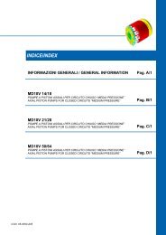
![Download Info Sheet [2MB .pdf]](https://img.yumpu.com/41465608/1/184x260/download-info-sheet-2mb-pdf.jpg?quality=85)
![Download .pdf [7.32MB] - Federal Fluid Power, Inc.](https://img.yumpu.com/39318737/1/190x245/download-pdf-732mb-federal-fluid-power-inc.jpg?quality=85)


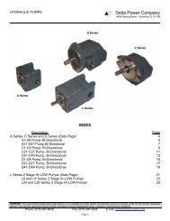
![Download Info Sheet [430KB .pdf] - Federal Fluid Power, Inc.](https://img.yumpu.com/39314496/1/190x245/download-info-sheet-430kb-pdf-federal-fluid-power-inc.jpg?quality=85)