

MD10V 14/18 - Federal Fluid Power, Inc.
MD10V 14/18 - Federal Fluid Power, Inc.
MD10V 14/18 - Federal Fluid Power, Inc.

Create successful ePaper yourself
Turn your PDF publications into a flip-book with our unique Google optimized e-Paper software.
<strong>MD10V</strong> <strong>14</strong>/<strong>18</strong>• Comandi - Controls:− Manuale senza azzeratoreManual without zeroing− Manuale con azzeratoreManual with zeroing− Manuale a leva retroazionatoManual lever with feed-back− Idraulico proporzionale non retroazionatoHydraulic proportional without feed-back− Elettrico ad impulsiElectric impulse− Elettrico 2 posizioniElectric two position<strong>MD10V</strong> 21/28• Caratteristiche Standard - Standard Feature:− Flangiatura SAE-ASAE-A Connection flange− Alberi Z9-16/32-DPShafts 9T-16/32-DP• Predisposizioni - Through drive:− Bosch Gr. 1- SAE “A” 9T - 16/32-DP− Bosch Gr. 2• Opzioni - Options:− Filtro in pressionePressure filter− Filettature GAS o UNFBSPP or UNF threads- Taglio ElettricoElectric Cut-Off• Comandi - Controls:− Idraulico proporzionale non retroazionatoHydraulic proportional without feed-back− Idraulico proporzionale retroazionatoHydraulic proportional with feed-back− Manuale a leva retroazionatoManual lever with feed-back− Elettrico 2 posizioniElectric two position− Elettronico proporzionale retroazionatoElectric proportional with feed-back− Elettrico ad impulsiElectric impulse• Caratteristiche Standard - Standard Feature:− Flangiatura SAE-BSAE-B Connection flange− Alberi Z13-16/32-DP o Z15-16/32-DPShafts 13T-16/32-DP or 15T-16/32-DP− Filtro in pressionePressure filter• Predisposizioni - Through drive:− SAE “A” 9T - 16/32-DP− SAE “B” 13T - 16/32-DP• Opzioni - Options:− Filettature GAS o UNFBSPP or UNF threads− Valvola BypassBypass valve− Limitatore di potenza<strong>Power</strong> limiter− Taglio ElettricoElectric Cut-Off− Attacchi supplementari manometroAdditional control pressure gauge portsPag. A/3
<strong>MD10V</strong> 50/64• Comandi - Controls:− Idraulico proporzionale non retroazionatoHydraulic proportional without feed-back− Idraulico proporzionale retroazionatoHydraulic proportional with feed-back− Manuale a leva retroazionatoManual lever with feed-back− Elettrico 2 posizioniElectric two position− Elettronico proporzionale retroazionatoElectric proportional with feed-back− Elettrico ad impulsiElectric impulse• Caratteristiche Standard - Standard Feature:− Flangiatura SAE-BSAE-B Connection flange− Albero Z15-16/32-DPShaft 15T-16/32-DP− Filtro in pressionePressure filter• Predisposizioni - Through drive:− SAE “A” 9T - 16/32-DP− SAE “B” 13T - 16/32-DP− SAE “B-B” 15T - 16/32-DP• Opzioni - Options:− Filettature GAS o UNFBSPP or UNF threads− Valvola BypassBypass valve− Limitatore di potenza<strong>Power</strong> limiter− Taglio ElettricoElectric Cut-Off− Attacchi supplementari manometroAdditional control pressure gaugePag. A/4
<strong>MD10V</strong> <strong>14</strong>/<strong>18</strong>POMPE A PISTONI ASSIALI PER CIRCUITOCHIUSO “MEDIA PRESSIONE”AXIAL PISTON PUMPS FOR CLOSEDCIRCUITS “MEDIUM PRESSURE”COD. 05-0052-A10Pag. B/1
RDESCRIZIONE - CARATTERISTICHEDESCRIPTION - FEATURES <strong>MD10V</strong> <strong>14</strong>/<strong>18</strong>1. IntroduzioneLa serie <strong>MD10V</strong> <strong>14</strong>/<strong>18</strong> comprende pompe a cilindrata variabiledel tipo a pistoni assiali utilizzate in circuito chiuso con corpo ecoperchio distributore in alluminio. La variazione di cilindrataavviene grazie alla rotazione di un piatto oscillante e andandooltre il punto di neutro si ottiene l’inversione del flusso. Le sceltetecnico costruttive consentono a questa unità di lavorare fino apressioni continue di 250 bar [3625 psi] con picchi di 300 bar[4350 psi].L’unità propone la seguente gamma di regolatori:• Manuale senza azzeratore• Manuale con azzeratore• Manuale a leva retroazionato• Idraulico proporzionale non retroazionato• Elettrico ad impulsi• Elettrico 2 posizioni (ON-OFF)In tutte le pompe è prevista una pompa di carico che reintegra idrenaggi, mantiene il circuito principale in pressione e fornisceolio al comando. Le pompe hanno incorporate le valvole dimassima pressione pre-tarate e possono essere fornite inversione singola o tandem.Sono disponibili due predisposizioni per il montaggio di pompeausiliarie e due opzioni accessorie:• Filtro in pressione• Valvola Taglio Elettrico• Predisposizione - Bosch Gr.1• Predisposizione - Bosch Gr.2• Predisposizione - SAE “A” Z9 - 16/32-DPPrincipali settori applicativi:• Macchine industriali.• Macchine movimento terra e da cantiere.• Macchine agricole e forestali.• Macchine per l’industria navale e Off-Shore.1. Introduction<strong>MD10V</strong> <strong>14</strong>/<strong>18</strong> series is a family of variable displacement axialpiston pumps for use in closed circuits with housing and distributorcover in aluminium. The displacement is continuouslyvariable by means of a tilting swash plate, and the oil flow directionis reversible. The design features allow this unit to operateup to a continuous pressures of 250 bar [3625 psi] with peaksof 300 bar [4350 psi].The following range of controls is available:• Manual without zeroing• Manual with zeroing• Manual lever with feed-back• Hydraulic proportional without feed-back• Electric impulse• Electric two position (ON-OFF)Each pump has a built in boost pump that makes up for internalleakage, maintains a positive pressure in the main circuit andprovides oil to the control system. All pumps have pre-set pressurerelief valves and can be supplied single or in tandem version.Two through drive options for auxiliary pump mounting and twooptions are available:• Pressure filter• Electric Cut-Off Valve• Through drive - Bosch Gr.1• Through drive - Bosch Gr.2• Through drive - SAE “A” 9T - 16/32-DPTypical application:• Industrial equipments.• Earth moving machines and construction machinery.• Agricultural and forestry machines.• Marine and Off-Shore equipments.Pag. B/2axial piston
RCODICI DI ORDINAZIONEORDERING CODELe seguenti 36 lettere o numeri del codice, sono state sviluppateper identificare tutte le configurazioni possibili delle pompe<strong>MD10V</strong>. Usare il seguente modulo per identificare le caratteristichedesiderate della pompa. Tutte le 36 lettere o numeri delcodice devono comparire in fase d’ordine. Si consiglia dileggere attentamente il catalogo prima di iniziare la compilazionedel codice di ordinazione.The following 36 alphanumeric digits system has been developedto identify all of the configuration options for the <strong>MD10V</strong>pump series. Use the model code below to specify a pump withthe desired features. All 36 alphanumeric digits system ofthe code must be present when ordering. We advise to carefullyread the catalogue before filling the ordering code.CODICE PRODOTTO / MODEL CODE1 2 3 4 5 6 7 7A 8 9 10 11 12 13 <strong>14</strong> 151 - SERIE / SERIES<strong>MD10V</strong>Pompa a pistoni assiali a cilindrata variabile per circuito chiuso “MEDIA PRESSIONE”Variable displacement axial piston pump for closed circuit “MEDIUM PRESSURE”2 - CILINDRATA / DISPLACEMENT<strong>14</strong><strong>18</strong>Cilindrata <strong>14</strong> cm 3 /giroDisplacement 0.85 in 3 /revCilindrata <strong>18</strong> cm 3 /giroDisplacement 1.09 in 3 /rev3 - VERSIONE ATTACCHI / PORTSMESEMetrica (Filetti BSPP)Metric (BSPP Threads)SAE (Filetti UNF)SAE (UNF Threads)A Richiesta (quantità minima 50 pezzi)Upon Request (minimum quantity 50 pieces)4 - ESTREMITÀ ALBERO / SHAFT END(1) Scanalato Z9-16/32-DP01Splined 9T-16/32-DP(2) Scanalato Z9-16/32-DP BOSCH02Splined 9T-16/32-DP BOSCH(3) Scanalato Femmina Z9-16/32-DP - TANDEM BOSCH03Internal Splined 9T-16/32-DP - TANDEM BOSCH(4) Scanalato Femmina Z9-16/32-DP - TANDEM04Internal Splined 9T-16/32-DP - TANDEM(5) Scanalato Z9-16/32-DP - Per predisposizione SAE-A21Splined 9T-16/32-DP - For through drive SAE-ASingolaSingle1^Tandem2^Tandem● ● ●● / ●/ / ●/ / ●● ● ●● Disponibile - Available/ Non Disponibile - Not AvailableNote:(1) Utilizzato per pompa singola.Utilizzato per prima pompa Tandem <strong>14</strong>/<strong>18</strong>+<strong>14</strong>/<strong>18</strong> versione corta.Utilizzato per seconda pompa Tandem <strong>14</strong>/<strong>18</strong>+<strong>14</strong>/<strong>18</strong>.Utilizzato per seconda pompa Tandem 21/28+<strong>14</strong>/<strong>18</strong>.Utilizzato per seconda pompa Tandem 50/64+<strong>14</strong>/<strong>18</strong>.(2) Utilizzato per pompa singola con predisposizione BOSCH.Utilizzato per seconda pompa Tandem <strong>14</strong>/<strong>18</strong>+<strong>14</strong>/<strong>18</strong> BOSCHUtilizzato per seconda pompa Tandem 21/28+<strong>14</strong>/<strong>18</strong> BOSCH.Utilizzato per seconda pompa Tandem 50/64+<strong>14</strong>/<strong>18</strong> BOSCH.(3) Utilizzato per seconda pompa Tandem <strong>14</strong>/<strong>18</strong>+<strong>14</strong>/<strong>18</strong> con predisposizioneBOSCH versione corta.(4) Utilizzato per seconda pompa Tandem <strong>14</strong>/<strong>18</strong>+<strong>14</strong>/<strong>18</strong> versione corta.(5) Utilizzato per pompa singola con predisposizione SAE-A.Utilizzato per prima pompa Tandem <strong>14</strong>/<strong>18</strong>+<strong>14</strong>/<strong>18</strong> con predisposizione SAE-A.Utilizzato per seconda pompa Tandem <strong>14</strong>/<strong>18</strong>+<strong>14</strong>/<strong>18</strong> con predisposizione SAE-A.Note:(1) Used for single pump.Used for first pump Tandem <strong>14</strong>/<strong>18</strong>+<strong>14</strong>/<strong>18</strong> short version.Used for second pump Tandem <strong>14</strong>/<strong>18</strong>+<strong>14</strong>/<strong>18</strong>Used for second pump Tandem 21/28+<strong>14</strong>/<strong>18</strong>.Used for second pump Tandem 50/64+<strong>14</strong>/<strong>18</strong>.(2) Used for single pump with through drive BOSCH.Used for second pump Tandem <strong>14</strong>/<strong>18</strong>+<strong>14</strong>/<strong>18</strong> BOSCHUsed for second pump Tandem 21/28+<strong>14</strong>/<strong>18</strong> BOSCH.Used for second pump Tandem 50/64+<strong>14</strong>/<strong>18</strong> BOSCH.(3) Used for second pump Tandem <strong>14</strong>/<strong>18</strong>+<strong>14</strong>/<strong>18</strong> with through drive BOSCH shortversion.(4) Used for second pump Tandem <strong>14</strong>/<strong>18</strong>+<strong>14</strong>/<strong>18</strong> short version.(5) Used for single pump with through drive SAE-A.Used for first pump Tandem <strong>14</strong>/<strong>18</strong>+<strong>14</strong>/<strong>18</strong> with through drive SAE-A.Used for second pump Tandem <strong>14</strong>/<strong>18</strong>+<strong>14</strong>/<strong>18</strong> with through drive SAE-A.Pag. B/3axial piston
R1 2 3 4 5 6 7 7A 8 9 10 11 12 13 <strong>14</strong> 155 - SENSO DI ROTAZIONE / DIRECTION OF ROTATIONDXSXDestraCWSinistraCCW6 - POMPA DI SOVRALIMENTAZIONE / CHARGE PUMP0500Cilindrata 5.4 cm 3 /giroDisplacement 0.33 in 3 /revSenza pompa di sovralimentazione (Versione Corta)Without Charge Pump (Short Version)SingolaSingle1^ Tandem2^Tandem● ● ●/ ● /● Disponibile - Available/ Non Disponibile - Not Available7 - REGOLATORI / CONTROLSHLWHLNHLRHINHEIHE2Manuale senza azzeratoreManual without zeroingManuale con azzeratoreManual with zeroingManuale a leva retroazionatoManual lever with feed-backIdraulico proporzionale non retroazionatoHydraulic proportional without feed-backElettrico ad impulsiElectric impulseElettrico 2 posizioniElectric two position7A - CARATTERISTICA REGOLATORE / CONTROL FEATURETensione di alimentazioneRegolatore / ControlVoltageHLW HLN HLR HIN HEI00Caratteristica non necessariaFeature not necessary● ● ● ● /12 12(V) / / / / ●24 24(V) / / / / ●● Disponibile - Available / Non Disponibile - Not AvailableHE2/●●8 - VALVOLA DI MASSIMA PRESSIONE RAMO A / PRESSURE RELIEF VALVE SIDE A<strong>14</strong>161721252730<strong>14</strong>0 bar[2030 psi]160 bar[2320 psi]170 bar[2465 psi]210 bar[3045 psi]250 bar[3625 psi]270 bar[3915 psi]300 bar[4350 psi]STANDARDPag. B/4axial piston
R1 2 3 4 5 6 7 7A 8 9 10 11 12 13 <strong>14</strong> 159 - VALVOLA DI MASSIMA PRESSIONE RAMO B / PRESSURE RELIEF VALVE SIDE B<strong>14</strong>161721252730<strong>14</strong>0 bar[2030 psi]160 bar[2320 psi]170 bar[2465 psi]210 bar[3045 psi]250 bar[3625 psi]270 bar[3915 psi]300 bar[4350 psi]STANDARD10 - VALVOLA DI MASSIMA PRESSIONE SOVRALIMENTAZIONE / CHARGE PRESSURE RELIEF VALVE10152010 bar[<strong>14</strong>5 psi]15 bar[217 psi]20 bar[290 psi]STANDARD11 - FILTRO / FILTER00FIFESenza FiltroWithout FilterCon FiltroWith FilterFiltro con sensore elettricoFilter with Electric sensorSTANDARDA RichiestaUpon RequestA RichiestaUpon RequestESTREMITÀ ALBERO / SHAFT END01 02 03 04 2100Nessuna PredisposizioneWithout through drive● / / ● /G1 Bosch GR1 / ● ● / /G2 Bosch GR2 / ● ● / /SA SAE A = Z9 - 16/32 DP / / / / ●TSTandem (Versione Corta) assemblataPump combination (Short Version)● / / / /TAPredisposizione Tandem per assemblaggio mediante SAE A = Z9 - 16/32 DPPump combination c/w through drive SAE A = 9T - 16/32 DP/ / / / ●12 - PREDISPOSIZIONI / THROUGH DRIVE● Disponibile - Availa-/ Non Disponibile - Not Available13 - LIMITAZIONE CILINDRATA RAMO A / DISPLACEMENT LIMITATION SIDE AXX00÷17Non RichiestaNot RequiredDa 0 cm 3 /giro a 17 cm 3 /giroFrom 0 cm 3 /giro To 17 cm 3 /giro<strong>14</strong> - LIMITAZIONE CILINDRATA RAMO B / DISPLACEMENT LIMITATION SIDE BXX00÷17Non RichiestaNot RequiredDa 0 cm 3 /giro a 17 cm 3 /giroFrom 0 cm 3 /giro To 17 cm 3 /giroPag. B/5axial piston
R1 2 3 4 5 6 7 7A 8 9 10 11 12 13 <strong>14</strong> 1515 - OPZIONI / OPTIONS00ADAENessuna OpzioneWithout OptionValvola Taglio Elettrico 12VElectric Cut-off valve 12VValvola Taglio Elettrico 24VElectric Cut-off valve 24VNon disponibile con predisposizione TSNot available with TS through driveNon disponibile con predisposizione TSNot available with TS through driveREGOLATORE / CONTROLHLW HLN HLR HIN HEI HE2● ● ● ● ● ●/ / ● ● / // / ● ● / /● Disponibile - Available/ Non Disponibile - Not AvailablePag. B/6axial piston
RCARATTERISTICHE TECNICHETECHNICAL FEATURES<strong>Fluid</strong>i:Utilizzare fluidi a base minerale con additivi anticorrosione, antiossidantie antiusura (HL o HM) con viscosità alla temperaturadi esercizio di 15÷60 cSt. Una viscosità limite di 800 cSt è ammissibilesolo per brevi periodi in condizione di partenza a freddo.Non sono ammesse viscosità inferiori ai 10 cSt. Viscositàcomprese tra i 10 e i 15 cSt sono tollerate solo in casi eccezionalie per brevi periodi.Temperature:Non è ammesso il funzionamento dell'unità a pistoni con temperaturedel fluido idraulico superiori a 80 ºC (176 °F) e inferiori a-25 ºC (-13 °F).Filtrazione in mandata:Al fine di migliorare il livello di contaminazione del fluido le unità<strong>MD10V</strong> <strong>14</strong>/<strong>18</strong> possono essere dotate di un filtro posizionatosulla bocca di mandata della pompa di sovralimentazione. Attraversol’elemento filtrante passa esclusivamente la portatache reintegra l’olio perso a causa dei drenaggi, tutta la portatain eccesso viene messa a scarico dalla valvola di sovralimentazionee non è quindi filtrata: in questo modo si garantisce unamaggiore durata del filtro. L’elemento presenta un setto filtrantein microfibra con un filtraggio di 22 micron assoluti (10 nominali).Per un corretto funzionamento dell'unità il livello di contaminazionemassimo ammesso nel circuito è 20/<strong>18</strong>/15 secondo lanorma ISO 4406:1999.Pressione di aspirazione:La pressione minima sulla bocca di aspirazione della pompa disovralimentazione è di 0.8 bar [11.6 psi] assoluti. All'avviamentoe per brevi istanti è tollerata una pressione assoluta di 0.5 bar[7.25 psi]. La pressione sulla bocca di aspirazione non devemai scendere al di sotto di tale valore.Pressione di esercizio:Pompa principale: La pressione massima continua ammissibilesulla bocca di mandata è di 250 bar [3625 psi] con picchi dipressione di 300 bar [4350 psi]. Pompa di sovralimentazione:La pressione nominale è di 10÷20 bar [<strong>14</strong>5÷290 psi]; Standard20 bar [290 psi]. La pressione massima ammissibile è di 35 bar[507 psi].Pressione in carcassa:La pressione massima in carcassa è di 2 bar [29 psi]. Per breviistanti all'avviamento della macchina è ammessa una pressionemassima di 6 bar [87 psi]. Una pressione superiore può comprometterela durata e la funzionalità della guarnizione dell'alberodi uscita.Guarnizioni:Le guarnizioni standard utilizzate sulle pompe <strong>MD10V</strong> <strong>14</strong>/<strong>18</strong>sono in NBR. Nel caso di impiego di fluidi speciali contattare laS.A.M. Hydraulik S.p.A.Limitazione della cilindrata:La pompa è dotata del dispositivo meccanico di limitazione dellacilindrata. La limitazione viene ottenuta mediante due granipresenti sul servocomando, i quali limitano la corsa del pistonedi comando.<strong>Fluid</strong>s:Use fluids with mineral oil basis and anticorrosive, antioxidantand wear preventing addition agents (HL or HM). Viscosity rangeat operating temperature must be of 15÷60 cSt. For shortperiods and upon cold start, a max.viscosity of 800 cSt is allowed.Viscosities less then 10 cSt are not allowed. A viscosityrange of 10 ÷15 cSt is allowed for extreme operating conditionsand for short periods only.Operating temperature:The operating temperature of the oil must be within -25 ºC ÷ 80ºC (-13 ºF ÷ 176 ºF). The running of the axial piston unit with oiltemperature higher than 80 ºC (176 °F)or lower than -25 ºC (-13°F)is not allowed.Filtration:In order to improve the control of the fluid contamination levelsthe <strong>MD10V</strong> <strong>14</strong>/<strong>18</strong> can be equipped with a boost flow filter positionedon the delivery outlet of the boost pump. Only the flownecessary to reintegrate the oil lost due to leakage will passthrough this filter, all the excess flow, which is dischargedthrough the boost pump valve is therefore not filtered to ensurea longer life of the filter cartridge. The filtering cartridge(microfibre) is a 22 micron absolute grade (10 micron nominal).In order to ensure a correct functioning of the unit, the max.permissible contamination level in the circuit is 20/<strong>18</strong>/15 accordingto ISO 4406:1999.Suction pressure:The minimum pressure on the auxiliary pump suction must beof 0.8 absolute bar [11.6 absolute psi]. On cold starting and forshort-term an absolute pressure of 0.5 bar [7.25 psi] is allowed.In no case inlet pressure can be lower.Operating pressure:Main pump: The maximum permissible continuous pressure onpressure ports is 250 bar [3625 psi]. Peak pressure is 300 bar[4350 psi]. Charge pump: The nominal pressure is 10÷20 bar[<strong>14</strong>5÷290 psi]; Standard 20 bar [290 psi]. Maximum admissiblepressure is 35 bar [507 psi].Case drain pressure:Maximum case drain pressure is 2 bar [29 psi]. On cold startingand for short-term a pressure of 6 bar [86 psi] is allowed. A higherpressure can damage the main shaft seal or reduce its life.Seals:Standard seals used on <strong>MD10V</strong> <strong>14</strong>/<strong>18</strong> pumps are NBR.In case of use special fluids, contact S.A.M. Hydraulik S.p.A.Displacement limiting:The pump is equiped with the displacement mechanical limitingdevice. Displacement limitation is obtained by means of twosetting screws which limit the control piston stroke.Pag. B/7axial piston
RCapacità di carico albero di uscita:L'albero di uscita è in grado di sopportare sia carichi radiali siaassiali. I carichi massimi ammissibili riportati in tabella sono talida garantire una durata dei supporti superiore all'80% delladurata in assenza di carichi.Drive shaft Radial and Axial loads:The drive shaft can stand both radial and axial loads. The maximumpermissible loads in the following table are calculated insuch a way as to guarantee a service life of at least 80%of theservice life of bearings to which no load is applied.Cilindrata / Displacement <strong>14</strong>/<strong>18</strong>Forza radialeRadial loadF q maxN[lbf]600[135]Forza assialeAxial loadF ax maxN[lbf]400[90]Installazione:Le pompe <strong>MD10V</strong> <strong>14</strong>/<strong>18</strong> possono essere installate in qualsiasidirezione e posizione. Per maggiori dettagli contattare la S.A.M.HydraulikInstallation:<strong>MD10V</strong> <strong>14</strong>/<strong>18</strong> series pumps can be installed in every position ordirection. For further details contact S.A.M. Hydraulik.Pag. B/8axial piston
RDATI TECNICITECHNICAL DATASERIE/SERIES <strong>MD10V</strong> <strong>14</strong>/<strong>18</strong>Cilindrata (1)Displacement (1)Cilindrata pompa di sovralimentazioneCharge pump displacementRegime massimo di rotazione (2)Max speed (2)Regime minimo di rotazioneMin speedPressione nominaleRated pressurePressione di piccoPeak pressurePressione di sovralimentazioneCharge pressurePressione massima in carcassaMax case pressurePressione di aspirazioneSuction pressureMomento d’inerzia parti rotantiMoment of inertia rotating partsMassa (3)Weight (3)cm 3 /giro[in 3 /rev]cm 3 /giro[in 3 /rev]giri/minrpmgiri/minrpmbar[psi]bar[psi]bar[psi]bar[psi]bar[psi]kg m 2[lb·ft 2 ]kg[lb]<strong>14</strong>-<strong>18</strong>[0.85-1.09]5.4[0.32]3600700250[3625]300[4350]10÷20 (standard 20)[<strong>14</strong>5÷290] [Standard 290]2[29]≥ 0.8[≥ 11.6]0.00<strong>14</strong>[0.033]7[15.4]Le condizioni di picco non devono durare più dell’ 1% di ogniminuto. Evitare il funzionamento contemporaneo alla massimavelocità e alla massima pressione.Peak operations must not excide 1% of every minute. A simultaneusmaximum pressure and maximum speed are not recommended.Note:(1) Le cilindrate <strong>14</strong>/<strong>18</strong> utilizzano la stessa struttura esterna.(2) I valori si intendono con pressione assoluta (p ass )di 1 bar [<strong>14</strong>.5psi] sulla bocca di aspirazione e olio minerale.(3) Valori indicativi.Notes:(1) The displacements <strong>14</strong>/<strong>18</strong> use the same external casing.(2) The values shown are valid for an absolute pressure (p ass ) of1 bar [<strong>14</strong>.5 psi] at the suction inlet port an when operated onmineral oil.(3) Approximate values.Pag. B/9axial piston
RREGOLATORE MANUALE SENZA AZZERATOREMANUAL WITHOUT ZEROING CONTROLHLWLa variazione di cilindrata della pompa viene ottenuta ruotandoil perno di comando in senso orario o antiorario (ad esempioper mezzo di una leva non fornita). Il perno é parte integrantedel piatto oscillante della pompa.The pump displacement variation of the pump is achieved rotatingthe control pivot (i.e. by the means of a lever - not supplied).The control pivot is buil tin the swash plate of the pump.Angolo/Angle (°)Vg/Vg max (%)La coppia necessaria da applicare al perno di comando:40 bar [580 psi] = Min 2 Nm [1.47 lbf·ft]Max 5 Nm [3.68 lbf·ft]200 bar [2900 psi] = Min 8 Nm [5.89 lbf·ft]Max 11 Nm [8.1 lbf·ft]The torque necessary on the control pivot:40 bar [580 psi] = Min 2 Nm [1.47 lbf·ft]Max 5 Nm [3.68 lbf·ft]200 bar [2900 psi] = Min 8 Nm [5.89 lbf·ft]Max 11 Nm [8.1 lbf·ft]Senso di rotazione: Correlazione tra il senso di rotazione dellapompa (visto dal lato albero) e l’azionamento del regolatore.Direction of rotation: Correlation between direction of rotation(shaft view) control and direction of flow.Rotazione alberoShaft rotationSINISTRO(CCW)DESTRO(CW)Direzione portata pompaPump flow directionRotazione comandoControl rotationMandata olio daOil outlet1 B2 A1 A2 BPag. B/10axial piston
RREGOLATORE MANUALE CON AZZERATOREMANUAL WITH ZEROING CONTROLHLNLa variazione di cilindrata della pompa viene ottenuta ruotandoil perno di comando in senso orario o antiorario (ad esempioper mezzo di una leva non fornita). Il perno é parte integrantedel piatto oscillante della pompa. Il ritorno a zero della pompaviene garantito dalla molla di richiamo interna.The pump displacement variation of the pump is achieved rotatingthe control pivot (i.e. by the means of a lever - not supplied).The control pivot is buil tin the swash plate of the pump.The return to zero displacement of the pump is guaranteed byan internal spring.Angolo/Angle (°)Vg/Vg max (%)La coppia necessaria da applicare al perno di comando:40 bar [580 psi] = Min 6 Nm [4.42 lbf·ft]Max 15 Nm [11.05 lbf·ft]200 bar [2900 psi] = Min 12 Nm [8.84 lbf·ft]Max 25 Nm [<strong>18</strong>.42 lbf·ft]The torque necessary on the control pivot:40 bar [580 psi] = Min 6 Nm [4.42 lbf·ft]Max 15 Nm [11.05 lbf·ft]200 bar [2900 psi] = Min 12 Nm [8.84 lbf·ft]Max 25 Nm [<strong>18</strong>.42 lbf·ft]Senso di rotazione: Correlazione tra il senso di rotazione dellapompa (visto dal lato albero) e l’azionamento del regolatore.Direction of rotation: Correlation between direction of rotation(shaft view) control and direction of flow.Rotazione alberoShaft rotationSINISTRO(CCW)DESTRO(CW)Direzione portata pompaPump flow directionRotazione comandoControl rotationMandata olio daOil outlet1 B2 A1 A2 BPag. B/11axial piston
RREGOLATORE MANUALE A LEVA RETROAZIONATOMANUAL LEVER WITH FEED-BACK CONTROLHLRLa pompa assume una cilindrata direttamente proporzionaleall'angolo impostato dalla leva. Per la relazione angolocilindratavedere il diagramma.The displacement of the pump is directly proportional to theangle of the lever. The diagram below shows the relationshipbetween angle and displacement.Angolo/Angle (°)Vg/Vg max (%)La coppia necessaria da applicare alla leva di controllo è compresa tra 0.6÷1.2 NmThe required torque on the control lever is normally between 0.6÷1.2 Nm [0.44÷0.88 lbf·ft].Il momento torcente massimo da applicare alla leva è 3 Nm.The maximum permissibile torque on the control lever is 3 Nm [2.21 lbf·ft].Senso di rotazione: Correlazione tra il senso di rotazione dellapompa e l’azionamento del regolatore.Direction of rotation: Relation between direction of rotationcontrol and direction of flow.Rotazione alberoShaft rotationSINISTRO(CCW)DESTRO(CW)Direzione portata pompaPump flow directionRotazione comandoControl rotationMandata olio daOil outlet1 A2 B1 B2 APag. B/12axial piston
RREGOLATORE IDRAULICO PROPORZIONALE NON RETROAZIONATOHYDRAULIC PROPORTIONAL WITHOUT FEED-BACK CONTROLHINLa pompa assume una cilindrata proporzionale alla pressionesugli attacchi “a” oppure “b” attraverso i quali si definisce oltreall'entità della portata anche il senso di mandata. Per l'alimentazionedel manipolatore si può sfruttare la pressione di sovralimentazioneprelevabile dalla porta P. La suddetta pressionepotrà poi essere regolata da un manipolatore o da una valvolariduttrice di pressione per il pilotaggio di “a” e “b” (non fornita).The pump displacement is proportional to the pilot pressure on“a” or “b” piloting ports, which also affect flow direction. Feedingpressure to the control joystick can be provided by charge pressurefrom P port. The piloting pressure must then be controlledby said joystick or by a pressure reducing valve (not supplied).Pressione/PressureBar [psi]Vg/Vg max (%)Pressione di pilotaggio = 4÷15 bar [58÷217 psi] (su a, b)Inizio regolazione = 4 bar [58 psi]Fine regolazione = 15 bar [217 psi](Massima cilindrata)Massima pressione applicabile su a,b = 25 bar [362 psi]Pilot pressure = 4÷15 bar [58÷217 psi] (at ports a, b)Start of control = 4 bar [58 psi]End of control = 15 bar [217 psi](Max displacement)Max pressure on a,b ports = 25 bar [362 psi]Senso di rotazione: Correlazione tra il senso di rotazione dellapompa (visto dal lato albero) e l’azionamento del regolatore.Direction of rotation: Correlation between direction of rotation(shaft view) control and direction of flow.Rotazione alberoShaft rotationSINISTRO(CCW)DESTRO(CW)Direzione portata pompaPump flow directionRotazione comandoControl rotationababMandata olio daOil outletBAABPag. B/13axial piston
RREGOLATORE ELETTROMAGNETICO AD IMPULSIELECTRIC IMPULSE CONTROLHEIComando ad impulsi in cui la pompa assume una cilindrata infunzione del tempo di eccitazione dell’elettrovalvola. Il servocomandoé senza molla azzeratrice quindi il pistone del servocomandouna volta mosso rimane nel punto in cui si trova fino allasuccessiva eccitazione dell’elettrovalvola. L'alimentazione dell'unoo dell'altro elettromagnete definisce il senso di mandata.Glielettromagneti standard sono del tipo ON-OFF a 24V c.c.corrente massima 1A. (Opzionali elettromagneti 12V c.c. correntemassima 2A).Impulse control where the displacement of the pump is functionof the number of inputs of current to one of the two proportionalsolenoids. The servocontro is without zeroing spring, thereforethe piston of the servocontrol stays in the position until a newinput of current is fed to the solenoids. Flow direction dependson which solenoid is energized. Standard solenoids are ON-OFF at 24V d.c. max. current 1A. (Optional solenoids 12V d.c.max. current 2A).Senso di rotazione: Correlazione tra il senso di rotazione dellapompa (visto dal lato albero) e l’azionamento del regolatore.Direction of rotation: Correlation between direction of rotation(shaft view) control and direction of flow.Rotazione alberoShaft rotationSINISTRO(CCW)DESTRO(CW)Direzione portata pompaPump flow directionRotazione comandoControl rotationMandata olio daOil outlet1 A2 B1 B2 APag. B/<strong>14</strong>axial piston
RREGOLATORE ELETTROMAGNETICO 2 POSIZIONIELECTRIC TWO POSITIONHE2Alimentando uno dei due elettromagneti ON-OFF (standard24V c.c. opzionale 12V c.c.), la pompa si porta alla cilindratamassima nel senso di mandata corrispondente al magnete eccitato.Togliendo l'alimentazione la pompa si porta in annullamentodi portata.By switching on one of the ON-OFF solenoids (standard 24Vd.c. optional 12V d.c.), the pump swivels to maximum displacementin the corresponding output flow direction. Switching offthe stated solenoid will result in swivelling back the pump tozero displacement position.Senso di rotazione: Correlazione tra il senso di rotazione dellapompa (visto dal lato albero) e l’azionamento del regolatore.Direction of rotation: Correlation between direction of rotation(shaft view) control and direction of flow.Rotazione alberoShaft rotationSINISTRO(CCW)DESTRO(CW)Direzione portata pompaPump flow directionRotazione comandoControl rotationMandata olio daOil outlet1 A2 B1 B2 APag. B/15axial piston
RFILTRO POMPA DI SOVRALIMENTAZIONEBOOSTER PUMP FILTER ON DELIVERY SIDEAl fine di garantire il mantenimento della condizioni di contaminazionedel fluido ottimali le unità <strong>MD10V</strong> possono essere dotate,di un filtro posizionato sulla bocca di mandata della pompadi sovralimentazione. Attraverso l’elemento filtrante passeràesclusivamente la portata che reintegrerà l’olio perso a causadel drenaggio, tutta la portata in eccesso, che verrà messa ascarico dalla valvola di sovralimentazione, non sarà quindi filtrata,in questo modo si garantisce una maggiore durata del filtro.A richiesta è possibile l’adozione dell’indicatore d’intasamentodel filtro in versione elettrica (Connettore DIN 43650A).Il filtro viene fornito su richiesta.In order to guarantee an optimum stability of the fluid contaminationconditions the <strong>MD10V</strong> can be equipped with a filter positionedon the delivery outlet of the booster pump. Only the flownecessary to reintegrate the lost oil due to drainage will passthrough this filter, all the excess flow, which is drained by thebooster pump valve, is therefore not filtered, in this way it isgarantee a longer life of the filter. Upon request it is possibile toadd an electrical filter clogging sensor (Connector DIN 43650A).The filter is supplied upon request.Sensore Elettrico / Electrical SensorContatti in scambioSPDTMax carico resistivoMax resistive loadMax carico induttivoMax inductive loadC.A.\ A.C. 125-250 V 1 A 1 AC.C.\ D.C. 30 V 2 A 2 AC.C.\ D.C. 50 V 0,5 A 0,5 AC.C.\ D.C. 75 V 0,25 A 0,25 AC.C.\ D.C. 125 V 0,2 A 0,03 ATAGLIO ELETTRICOELECTRIC CUT-OFFLa valvola di taglio elettrico annulla la cilindrata della pompaquando viene tolta l’alimentazione all’elettromagnete ON/OFFdella valvola. La tensione di alimentazione dell’elettromagnete èdi 12 o 24 Volt. La valvola può essere montata sulle pompeequipaggiate con i seguenti regolatori : HIN - HLR.Non si può montare in aggiunta al Limitatore di potenza e Nonsi può montare sulle pompe tandem versione corta.CONNETTORE = DIN43650AThe electric cut-off valve, brings to zero the displacement of thepump when power supply to the ON/OFF solenoid is cut-off.Feed voltage is 12V d.c or 24V d.c. The electric cut-off valvecan be assembled on pumps equipped with one of the followingcontrols: HIN - HLRIs not possible to assembled the cut-off valve with power limiterand in the Tandem pump short version.CONNECTOR = DIN43650APag. B/16axial piston
RDIMENSIONI POMPA E REGOLATORIPUMP AND CONTROLS DIMENSIONS <strong>MD10V</strong> <strong>14</strong>/<strong>18</strong>Pompa <strong>MD10V</strong> <strong>14</strong>/<strong>18</strong> - Flangia SAE A - Regolatore HLW<strong>MD10V</strong> <strong>14</strong>/<strong>18</strong> Pump - Mounting flange SAE A - HLW ControlVersione METRICA / METRIC VersionA-B: Linee in pressione / Pressure ports - 3/8 G (BSPP)D1-D2: Drenaggi / Drain port - 3/8 G (BSPP)S: Aspirazione / Suction port - 1/2 G (BSPP)P: Sovralimentazione / Charge pressure port - 1/4 G (BSPP)Va: Valvola di alimentazione / Charge pump valveV1-V2: Valvole di massima / Maximum pressure valvesSI: Limitatore di cilindrata / Stroke limiterVersione SAE / SAE VersionA-B: Linee in pressione / Pressure ports - 9/16 - <strong>18</strong> UNF - 2BD1-D2: Drenaggi / Drain port - 9/16 - <strong>18</strong> UNF - 2BS: Aspirazione / Suction port - 3/4 - 16 UNF - 2BP: Sovralimentazione / Charge pressure port - 7/16 - 20 UNF - 2BVa: Valvola di alimentazione / Charge pump valveV1-V2: Valvole di massima / Maximum pressure valvesSI: Limitatore di cilindrata / Stroke limiterPag. B/17axial piston
RPompa <strong>MD10V</strong> <strong>14</strong>/<strong>18</strong> - Flangia SAE A - Regolatore HLN<strong>MD10V</strong> <strong>14</strong>/<strong>18</strong> Pump - Mounting flange SAE A - HLN ControlZm: Vite azzeratore meccanicoMechanical zero adjustment screwPompa <strong>MD10V</strong> <strong>14</strong>/<strong>18</strong> - Flangia SAE A - Regolatore HLR<strong>MD10V</strong> <strong>14</strong>/<strong>18</strong> Pump - Mounting flange SAE A - HLR ControlZm: Vite azzeratore meccanicoMechanical zero adjustment screwPompa <strong>MD10V</strong> <strong>14</strong>/<strong>18</strong> - Flangia SAE A - Regolatore HEI<strong>MD10V</strong> <strong>14</strong>/<strong>18</strong> Pump - Mounting flange SAE A - HEI ControlPag. B/<strong>18</strong>axial piston
RPompa <strong>MD10V</strong> <strong>14</strong>/<strong>18</strong> - Flangia SAE A - Regolatore HE2<strong>MD10V</strong> <strong>14</strong>/<strong>18</strong> Pump - Mounting flange SAE A - HE2 ControlPompa <strong>MD10V</strong> <strong>14</strong>/<strong>18</strong> - Flangia SAE A - Regolatore HIN<strong>MD10V</strong> <strong>14</strong>/<strong>18</strong> Pump - Mounting flange SAE A - HIN ControlVersione METRICA / METRIC Versiona-b: Attacchi per pilotaggio Comando - 1/4 G (BSPP)Control piloting pressure port - 1/4 G (BSPP)Zm: Vite azzeratore meccanicoMechanical zero adjustment screwVersione SAE / SAE Versiona-b: Attacchi per pilotaggio Comando - 7/16 - 20 UNF - 2BControl piloting pressure port - 7/16 - 20 UNF - 2BZm: Vite azzeratore meccanicoMechanical zero adjustment screwPag. B/19axial piston
RDIMENSIONI POMPA TANDEMCOMBINATION PUMP DIMENSIONSTANDEM <strong>MD10V</strong> <strong>14</strong>/<strong>18</strong>+<strong>14</strong>/<strong>18</strong>VERSIONE CORTA / SHORT VERSIONPompaPumpAlberi per pompe in tandem / Shafts for combination pumpsConfigurazioniConfiguration<strong>MD10V</strong> <strong>14</strong>/<strong>18</strong> + <strong>MD10V</strong> <strong>14</strong>/<strong>18</strong>Versione corta / Short versionAlberi / Shafts 01 03 o 04 (1)1 a1st.2 a2nd.Con questa configurazione, solo la seconda pompa monta lapompa di sovralimentazione(1) 03 - Albero Scanalato femmina Z9 - 16/32 - DP (Pred.Bosch)04 - Albero Scanalato femmina Z9 - 16/32 - DPAttenzione: Quando si ordina una pompa tandem è necessariospecificare per entrambe le pompe il tipo di albero e la predisposizionerichiesta. Nella versione corta le pompe saranno spedite montate, in fased’ordine la prima pompa dovrà possedere la predisposizione TS (Vederepunto 12 del codice di ordinazione).With this configuration, only the second pump mount the chargepump.(1) 03 - Internal splined shaft 9T - 16/32 - DP (Through driveBosch)04 - Internal splined shaft 9T - 16/32 - DPWarning: Ordering a tandem pump it is necessary to indicate for eachpump the kind of shaft and the through drive option needed. In the shortversion the pumps will be send assembled together, on the purchaseorder, the first pump will need the through drive TS (see position 12 ofordering code).SCHEMA IDRAULICO TANDEM (TS) VERSIONE CORTA / SHORT VERSION TANDEM (TS) HYDRAULIC LAYOUTIl tubo (1) che collega gli attacchi della pressione di sovralimentazione(P) è fornito di serie. I tubi (2) e (3) che collegano idrenaggi, devono essere realizzati a cura del cliente.The hose (1) used to connect the charge pressure ports (P) issupplied with the units. The hoses (2) and (3) connecting thedrain ports must be relized and mounted by the customerPag. B/22axial piston
RTANDEM <strong>MD10V</strong> <strong>14</strong>/<strong>18</strong>+<strong>14</strong>/<strong>18</strong>PompaPumpAlberi per pompe in tandem / Shafts for combination pumpsConfigurazioniConfiguration<strong>MD10V</strong> <strong>14</strong>/<strong>18</strong> + <strong>MD10V</strong> <strong>14</strong>/<strong>18</strong>Alberi / Shafts 21 01 - 02 - 21 (1)1 a1st.2 a2nd.Con questa configurazione, entrambe le pompe montano lapompa di sovralimentazione.(1) 01 - Albero Scanalato Z9 - 16/32 - DP02 - Albero Scanalato Z9 - 16/32 - DP (Pred. Bosch)21 - Albero Scanalato Z9 - 16/32 - DP (Pred. SAE-A)Attenzione: Quando si ordina una pompa tandem è necessariospecificare per entrambe le pompe il tipo di albero e la predisposizionerichiesta. Se le pompe devono essere spedite montate, in fase d’ordine laprima pompa dovrà possedere la predisposizione TA (Vedere punto 12del codice di ordinazione).With this configuration, both the pumps mount the chargepump.(1) 01 - Splined shaft 9T - 16/32 - DP02 - Splined shaft 9T - 16/32 - DP (Through drive Bosch)21 - Splined shaft 9T - 16/32 - DP (Through drive SAE-A)Warning: Ordering a tandem pump it is necessary to indicate for eachpump the kind of shaft and the through drive option needed. If the pumpsneed to be assembled together, on the purchase order, the first pump willneed the through drive TA (see position 12 of ordering code).Pag. B/23axial piston
RDIMENSIONI PRESE DI MOTOTHROUGH DRIVES DIMENSIONSFlangia Bosch GR1Bosch GR1 Flange(*)(*)Giunto non fornito(*)Coupling not suppliedFlangia Bosch GR2Bosch GR2 Flange(*)(*)Giunto non fornito(*)Coupling not suppliedPag. B/24axial piston
RFlangia SAE ASAE A FlangePag. B/25axial piston
RPag. B/26axial piston
<strong>MD10V</strong> 21/28POMPE A PISTONI ASSIALI PER CIRCUITOCHIUSO “MEDIA PRESSIONE”AXIAL PISTON PUMPS FOR CLOSEDCIRCUITS “MEDIUM PRESSURE”COD. 05-0051-A16Pag. C/1
RDESCRIZIONE - CARATTERISTICHEDESCRIPTION - FEATURES <strong>MD10V</strong> 21/281. IntroduzioneLa serie <strong>MD10V</strong> 21/28 comprende pompe a cilindrata variabiledel tipo a pistoni assiali utilizzate in circuito chiuso. Lavariazione di cilindrata avviene grazie alla rotazione di un piattooscillante e andando oltre il punto di neutro si ottienel’inversione del flusso. Le scelte tecnico costruttive consentonoa questa unità di lavorare fino a pressioni continue di 250 bar[3625 psi] con picchi di 300 bar [4350 psi].L’unità propone la seguente gamma di regolatori:• Idraulico proporzionale non retroazionato• Idraulico proporzionale retroazionato• Manuale a leva retroazionato• Elettrico 2 posizioni (ON-OFF)• Elettrico proporzionale retroazionato• Elettrico ad impulsiIn tutte le pompe è prevista una pompa di carico che reintegra idrenaggi, mantiene il circuito principale in pressione e fornisceolio al comando. Le pompe hanno incorporate le valvole dimassima pressione pre-tarate e possono essere fornite inversione singola o tandem. Ogni pompa è dotata di serie di unfiltro posizionato sulla bocca di mandata della pompa disovralimentazione.Sono disponibili due predisposizioni per il montaggio di pompeausiliarie e tre opzioni accessorie:• Valvola Bypass• Limitatore di potenza• Valvola Taglio Elettrico• Attacchi supplementari manometro• Predisposizione - SAE “A” Z9 - 16/32-DP• Predisposizione - SAE “B” Z13 - 16/32-DPPrincipali settori applicativi:• Macchine industriali.• Macchine movimento terra e da cantiere.• Macchine agricole e forestali.• Macchine per l’industria navale e Off-Shore.1. Introduction<strong>MD10V</strong> 21/28 series is a family of variable displacement axialpiston pumps for use in closed circuits. The displacement iscontinuously variable by means of a tilting swash plate, and theoil flow direction is reversible. The design features allow thisunit to operate up to a continuous pressures of 250 bar [3625psi] with peaks of 300 bar [4350 psi].The following range of controls is available:• Hydraulic proportional without feed-back• Hydraulic proportional with feed-back• Manual lever with feed-back• Electric two position (ON-OFF)• Electric proportional with feed-back• Electric impulseEach pump has a built in boost pump that makes up for internalleakage, maintains a positive pressure in the main circuit andprovides oil to the control system. All pumps have pre-set pressurerelief valves and can be supplied single or in tandem version.Every pump is supplied with a boost pressure filter positionedon the pressure outlet of the boost pump.Two through drive options for auxiliary pump mounting andthree of options are available:• Bypass valve• <strong>Power</strong> limiter• Electric Cut-Off Valve• Additional control pressure gauge ports• Through drive - SAE “A” 9T - 16/32-DP• Through drive - SAE “B” 13T - 16/32-DPTypical application:• Industrial equipments.• Earth moving machines and construction machinery.• Agricultural and forestry machines.• Marine and Off-Shore equipments.Pag. C/2axial piston
RCODICI DI ORDINAZIONEORDERING CODELe seguenti 36 lettere o numeri del codice, sono state sviluppateper identificare tutte le configurazioni possibili delle pompe<strong>MD10V</strong>. Usare il seguente modulo per identificare le caratteristichedesiderate della pompa. Tutte le 36 lettere o numeri delcodice devono comparire in fase d’ordine. Si consiglia dileggere attentamente il catalogo prima di iniziare la compilazionedel codice di ordinazione.The following 36 alphanumeric digits system has been developedto identify all of the configuration options for the <strong>MD10V</strong>pump series. Use the model code below to specify a pump withthe desired features. All 36 alphanumeric digits system ofthe code must be present when ordering. We advise to carefullyread the catalogue before filling the ordering code.CODICE PRODOTTO / MODEL CODE1 2 3 4 5 6 7 7A 8 9 10 11 12 13 <strong>14</strong> 151 - SERIE / SERIES<strong>MD10V</strong>2128Pompa a pistoni assiali a cilindrata variabile per circuito chiuso “MEDIA PRESSIONE”Variable displacement axial piston pump for closed circuit “MEDIUM PRESSURE”2 - CILINDRATA / DISPLACEMENTMESECilindrata 21 cm 3 /giroDisplacement 1.28 in 3 /revCilindrata 28 cm 3 /giroDisplacement 1.71 in 3 /rev3 - VERSIONE ATTACCHI / PORTSMetrica (Filetti BSPP)Metric (BSPP Threads)SAE (Filetti UNF)SAE (UNF Threads)4 - ESTREMITÀ ALBERO / SHAFT END(1) Scanalato Z13-16/32-DP06Splined 13T-16/32-DP(2) Scanalato Z15-16/32-DP TANDEM09Splined 15T-16/32-DP TANDEM(4) Scanalato Z15-16/32-DP08Splined 15T-16/32-DP(3) Scanalato Femmina Z13-16/32-DP - TANDEM07Internal Splined 13T-16/32-DP - TANDEM● Disponibile - Available/ Non Disponibile - Not AvailableNote:(1) Utilizzato per pompa singola..Utilizzato per prima pompa Tandem 21/28+<strong>14</strong>/<strong>18</strong> con predisposizione SAE A.Utilizzato per seconda pompa Tandem 21/28+21/28.Utilizzato per seconda pompa Tandem 50/64+21/28.(2) Utilizzato per prima pompa Tandem 21/28+21/28 versione corta.Utilizzato per prima pompa Tandem 21/28+21/28 con predisposizione SAE B(3) Utilizzato per seconda pompa Tandem 21/28+21/28 versione corta.(4) Utilizzato per pompa singola.Utilizzato per prima pompa Tandem 21/28+<strong>14</strong>/<strong>18</strong> con predisposizione SAE A.A Richiesta (quantità minima 50 pezzi)Upon Request (minimum quantity 50 pieces)SingolaSingle1^Tandem2^Tandem● ● ●● ● /● ● /● ● /Note:(1) Used for Single pump.Used for first pump Tandem 21/28+<strong>14</strong>/<strong>18</strong> with through drive SAE A.Used for second pump Tandem 21/28+21/28.Used for second pump Tandem 50/64+21/28.(2) Used for first pump Tandem 21/28+21/28 short version.Used for first pump Tandem 21/28+21/28 with through drive SAE B.(3) Used for second pump Tandem 21/28+21/28 short version.(4) Used for Single pump.Used for first pump Tandem 21/28+<strong>14</strong>/<strong>18</strong> with through drive SAE A.5 - SENSO DI ROTAZIONE / DIRECTION OF ROTATIONDXSXDestraCWSinistraCCW6 - POMPA DI SOVRALIMENTAZIONE / CHARGE PUMP1100Cilindrata 11 cm 3 /giroDisplacement 0.67 in 3 /revSenza pompa di sovralimentazione (Versione Corta)Without charge Pump (Short Version)SingolaSingle1^Tandem2^Tandem● ● ●/ ● /● Disponibile - Available/ Non Disponibile - Not AvailablePag. C/3axial piston
R1 2 3 4 5 6 7 7A 8 9 10 11 12 13 <strong>14</strong> 157 - REGOLATORI / CONTROLSHINHIRHLRHE2HERHEIIdraulico proporzionale non retroazionatoHydraulic proportional without feed-backIdraulico proporzionale retroazionatoHydraulic proportional with feed-backManuale a leva retroazionatoManual lever with feed-backElettrico 2 posizioniElectric two positionElettrico proporzionale retroazionatoElectric proportional with feed-backElettrico ad impulsiElectric impulse7A - CARATTERISTICA REGOLATORE / CONTROL FEATURETensione di alimentazioneRegolatore / ControlVoltageHIN HIR HLR HE2 HER HEI00Caratteristica non necessariaFeature not necessary● ● ● / / /12 12(V) / / / ● ● ●24 24(V) / / / ● ● ●● Disponibile - Available8 - VALVOLA DI MASSIMA PRESSIONE RAMO A / PRESSURE RELIEF VALVE SIDE A<strong>14</strong>161721252730<strong>14</strong>0 bar[2030 psi]160 bar[2320 psi]170 bar[2465 psi]210 bar[3045 psi]250 bar[3625 psi]270 bar[3915 psi]300 bar[4350 psi]/ Non Disponibile - Not AvailableSTANDARD9 - VALVOLA DI MASSIMA PRESSIONE RAMO B / PRESSURE RELIEF VALVE SIDE B<strong>14</strong>161721252730<strong>14</strong>0 bar[2030 psi]160 bar[2320 psi]170 bar[2465 psi]210 bar[3045 psi]250 bar[3625 psi]270 bar[3915 psi]300 bar[4350 psi]STANDARD10 - VALVOLA DI MASSIMA PRESSIONE SOVRALIMENTAZIONE / CHARGE PRESSURE RELIEF VALVE15202515 bar[217 psi]20 bar[290 psi]25 bar[362 psi]STANDARDPag. C/4axial piston
R1 2 3 4 5 6 7 7A 8 9 10 11 12 13 <strong>14</strong> 1511 - FILTRO / FILTER00FIFE00Senza FiltroWithout FilterCon FiltroWith FilterFiltro con sensore elettricoFilter with Electric sensor12 - PREDISPOSIZIONI / THROUGH DRIVENessuna PredisposizioneWithout through driveSTANDARDESTREMITÀ ALBERO / SHAFT END06 09 08 07● / ● ●SA SAE A = Z9 - 16/32 DP ● / ● ●SB SAE B = Z13 16/32 DP / ● / /TAPredisposizione Tandem per assemblaggio mediante SAE A = Z9 - 16/32 DPPump combination c/w through drive SAE A = 9T - 16/32 DP● / ● /TBPredisposizione Tandem per assemblaggio mediante SAE B = Z13 16/32 DPPump combination c/w through drive SAE B = 13T 16/32 DP/ ● / /TSTandem (Versione Corta) assemblataPump combination (Short Version)/ ● / /● Disponibile - Available/ Non Disponibile - Not Available13 - LIMITAZIONE CILINDRATA RAMO A / DISPLACEMENT LIMITATION SIDE AXX00÷27Non RichiestaNot RequiredDa 0 cm 3 /giro a 27 cm 3 /giroFrom 0 cm 3 /giro To 27 cm 3 /giro<strong>14</strong> - LIMITAZIONE CILINDRATA RAMO B / DISPLACEMENT LIMITATION SIDE BXX00÷2700Non RichiestaNot RequiredDa 0 cm 3 /giro a 27 cm 3 /giroFrom 0 cm 3 /giro To 27 cm 3 /giro15 - OPZIONI / OPTIONSNessuna OpzioneWithout OptionREGOLATORE / CONTROLHIN HIR HLR HE2 HER HEI● ● ● ● ● ●01 By pass ● ● ● ● ● ●0205Limitatore di potenza (annullamento a 270 bar)<strong>Power</strong> limiter [destroke at 3915 psi]Attacchi supplementari manometroAdditional control pressure gauge portsContattare Servizio TecnicoContact Technical Department● ● ● ● ● ●● ● ● ● ● ●By pass + Attacchi supplementari manometroAH ● ● ● ● ● ●By pass + Additional control pressure gauge portsAAADAEAIALLimitatore di potenza (annullamento a 270 bar) + By pass<strong>Power</strong> limiter [destroke at 3915 psi] + By passValvola Taglio Elettrico 12VElectric Cut-off valve 12VValvola Taglio Elettrico 24VElectric Cut-off valve 24VBy pass + Valvola Taglio Elettrico 12VBy pass + Electric Cut-off valve 12VBy pass + Valvola Taglio Elettrico 24VBy pass + Electric Cut-off valve 24VContattare Servizio TecnicoContact Technical DepartmentNon disponibile con predisposizione TSNot available with TS through driveNon disponibile con predisposizione TSNot available with TS through driveNon disponibile con predisposizione TSNot available with TS through driveNon disponibile con predisposizione TSNot available with TS through drive● ● ● ● ● ●● / ● / / /● / ● / / /● / ● / / /● / ● / / /● Disponibile - Available/ Non Disponibile - Not AvailablePag. C/5axial piston
RCARATTERISTICHE TECNICHETECHNICAL FEATURES<strong>Fluid</strong>i:Utilizzare fluidi a base minerale con additivi anticorrosione, antiossidantie antiusura (HL o HM) con viscosità alla temperaturadi esercizio di 15 ÷60 cSt. Una viscosità limite di 800 cSt è ammissibilesolo per brevi periodi in condizione di partenza a freddo.Non sono ammesse viscosità inferiori ai 10 cSt. Viscositàcomprese tra i 10 e i 15 cSt sono tollerate solo in casi eccezionalie per brevi periodi.Temperature:Non è ammesso il funzionamento dell'unità a pistoni con temperaturedel fluido idraulico superiori a 80 ºC (176 °F) e inferiori a-25 ºC (-13 °F).Filtrazione in mandata:Al fine di migliorare il livello di contaminazione del fluido le unità<strong>MD10V</strong> 21/28 sono dotate di un filtro posizionato sulla bocca dimandata della pompa di sovralimentazione. Attraverso l’elementofiltrante passa esclusivamente la portata che reintegral’olio perso a causa dei drenaggi, tutta la portata in eccessoviene messa a scarico dalla valvola di sovralimentazione e nonè quindi filtrata: in questo modo si garantisce una maggioredurata del filtro. L’elemento presenta un setto filtrante in microfibracon un filtraggio di 22 micron assoluti (10 nominali).Per un corretto funzionamento dell'unità il livello di contaminazionemassimo ammesso nel circuito è 20/<strong>18</strong>/15 secondo lanorma ISO 4406:1999.Pressione di aspirazione:La pressione minima sulla bocca di aspirazione della pompa disovralimentazione è di 0.8 bar [11.6 psi] assoluti. All'avviamentoe per brevi istanti è tollerata una pressione assoluta di 0.5 bar[7.25 psi]. La pressione sulla bocca di aspirazione non devemai scendere al di sotto di tale valore.Pressione di esercizio:Pompa principale: La pressione massima continua ammissibilesulla bocca di mandata è di 250 bar [3625 psi] con picchi dipressione di 300 bar [4350 psi]. Pompa di sovralimentazione:La pressione nominale è di 15÷25 bar [2<strong>18</strong>÷363 psi]; Standard20 bar [290 psi]. La pressione massima ammissibile è di 35 bar[507 psi].Pressione in carcassa:La pressione massima in carcassa è di 2 bar [29 psi]. Per breviistanti all'avviamento della macchina è ammessa una pressionemassima di 6 bar [87 psi]. Una pressione superiore può comprometterela durata e la funzionalità della guarnizione dell'alberodi uscita.Guarnizioni:Le guarnizioni standard utilizzate sulle pompe <strong>MD10V</strong> 21/28sono in NBR. Nel caso di impiego di fluidi speciali contattare laS.A.M. Hydraulik S.p.A.Limitazione della cilindrata:La pompa è dotata del dispositivo meccanico di limitazione dellacilindrata. La limitazione viene ottenuta mediante due granipresenti sul servocomando, i quali limitano la corsa del pistonedi comando.<strong>Fluid</strong>s:Use fluids with mineral oil basis and anticorrosive, antioxidantand wear preventing addition agents (HL or HM). Viscosityrange at operating temperature must be of 15÷60 cSt. For shortperiods and upon cold start, a max. viscosity of 800 cSt is allowed.Viscosities less then 10 cSt are not allowed. A viscosityrange of 10 ÷15 cSt is allowed for extreme operating conditionsand for short periods only.Operating temperature:The operating temperature of the oil must be within -25 ºC ÷ 80ºC (-13 ºF ÷ 176 ºF). The running of the axial piston unit with oiltemperature higher than 80 ºC (176 °F) or lower than -25 ºC (-13 °F) is not allowed.Filtration:In order to improve the control of the fluid contamination levelsthe <strong>MD10V</strong> 21/28 is equipped with a boost flow filter positionedon the delivery outlet of the boost pump. Only the flow necessaryto reintegrate the oil lost due to leakage will pass throughthis filter, all the excess flow, which is discharged through theboost pump valve is therefore not filtered to ensure a longer lifeof the filter cartridge. The filtering cartridge (microfibre) is a 22micron absolute grade (10 micron nominal).In order to ensure a correct functioning of the unit, the max.permissible contamination level in the circuit is 20/<strong>18</strong>/15 accordingto ISO 4406:1999.Suction pressure:The minimum pressure on the boost pump suction port must beof 0.8 absolute bar [11.6 absolute psi]. On cold starting and forshort periods an absolute pressure of 0.5 bar [7.25 psi] is allowed.In no case inlet pressure can be lower.Operating pressure:Main pump: The maximum permissible continuous pressure onpressure ports is 250 bar [3625 psi]. Peak pressure is 300 bar[4350 psi]. Charge pump: The nominal pressure is 15÷25 bar[2<strong>18</strong>÷363 psi]; Standard 20 bar [290 psi]. Maximum admissiblepressure is 35 bar [507 psi].Case drain pressure:Maximum case drain pressure is 2 bar [29 psi]. On cold startingand for short periods a pressure of 6 bar [86 psi] is allowed. Ahigher pressure can damage the main shaft seal or reduce itslife.Seals:Standard seals used on <strong>MD10V</strong> 21/28 pumps are NBR.In case of use special fluids, contact S.A.M. Hydraulik S.p.A.Displacement limiting:The pump is equipped with mechanical displacement limitingdevice. Displacement limitation is obtained by means of twosetting screws which limit the control piston stroke.Pag. C/6axial piston
RCapacità di carico albero di uscita:L'albero di uscita è in grado di sopportare sia carichi radiali siaassiali. I carichi massimi ammissibili riportati in tabella sono talida garantire una durata dei supporti superiore all'80% delladurata in assenza di carichi.Drive shaft Radial and Axial loads:The drive shaft can stand both radial and axial loads. The maximumpermissible loads in the following table are calculated insuch a way as to guarantee a service life of at least 80%of theservice life of bearings to which no load is applied.Cilindrata / Displacement 21/28Forza radialeRadial loadF q maxN[lbf]1200[270]Forza assialeAxial loadF ax maxN[lbf]950[213]Installazione:Le pompe <strong>MD10V</strong> 21/28 possono essere installate in qualsiasidirezione e posizione. Per maggiori dettagli contattare la S.A.M.Hydraulik.Installation:<strong>MD10V</strong> 21/28 series pumps can be installed in every position ordirection. For further details contact S.A.M. Hydraulik.Pag. C/7axial piston
RDATI TECNICITECHNICAL DATASERIE/SERIES <strong>MD10V</strong> 21/28Cilindrata (1)Displacement (1)Cilindrata pompa di sovralimentazioneCharge pump displacementRegime massimo di rotazione (2)Max speed (2)Regime minimo di rotazioneMin speedPressione nominaleRated pressurePressione di piccoPeak pressurePressione di sovralimentazioneCharge pressurePressione massima in carcassaMax case pressurePressione di aspirazioneSuction pressureMomento d’inerzia parti rotantiMoment of inertia rotating partsMassa (3)Weight (3)cm 3 /giro[in 3 /rev]cm 3 /giro[in 3 /rev]giri/minrpmgiri/minrpmbar[psi]bar[psi]bar[psi]bar[psi]bar[psi]kg m 2[lbf·ft 2 ]kg[lb]21-28[1.28-1.71]11[0.671]3600700250[3625]300[4350]15÷25 (standard 20)[2<strong>18</strong>÷363] [Standard 290]2[29]≥ 0.8[≥ 11.6]0.00<strong>18</strong>[0.042]22[48.48]Le condizioni di picco non devono durare più dell’ 1% di ogniminuto. Evitare il funzionamento contemporaneo alla massimavelocità e alla massima pressione.Peak operations must not excide 1% of every minute. A simultaneusmaximum pressure and maximum speed are not recommended.Note:(1) Le cilindrate 21/28 utilizzano la stessa struttura esterna.(2) I valori si intendono con pressione assoluta (p ass )di 1 bar [<strong>14</strong>.5psi] sulla bocca di aspirazione e olio minerale.(3) Valori indicativi.Notes:(1) The displacements 21/28 use the same external casing.(2) The values shown are valid for an absolute pressure (p ass ) of1 bar [<strong>14</strong>.5 psi] at the suction inlet port an when operated onmineral oil.(3) Approximate values.Pag. C/8axial piston
RREGOLATORE MANUALE A LEVA RETROAZIONATOMANUAL LEVER WITH FEED-BACK CONTROLHLRLa pompa assume una cilindrata direttamente proporzionaleall'angolo impostato dalla leva. Per la relazione angolocilindratavedere il diagramma.The displacement of the pump is directly proportional to theangle of the lever. The diagram below shows the relationshipbetween angle and displacement.Angolo/Angle (°)Vg/Vg max (%)La coppia necessaria da applicare alla leva di controllo è compresa tra 0.6÷1.2 NmThe required torque on the control lever is normally between 0.6÷1.2 Nm [0.44÷0.88 lbf·ft].Il momento torcente massimo da applicare alla leva è 3 Nm.The maximum permissibile torque on the control lever is 3 Nm [2.21 lbf·ft].Senso di rotazione: Correlazione tra il senso di rotazione dellapompa e l’azionamento del regolatore.Direction of rotation: Relation between direction of rotationcontrol and direction of flow.Rotazione alberoShaft rotationSINISTRO(CCW)DESTRO(CW)Direzione portata pompaPump flow directionRotazione comandoControl rotationMandata olio daOil outlet1 A2 B1 B2 APag. C/9axial piston
RREGOLATORE IDRAULICO PROPORZIONALE NON RETROAZIONATOHYDRAULIC PROPORTIONAL WITHOUT FEED-BACK CONTROLHINLa pompa assume una cilindrata proporzionale alla pressionesugli attacchi “a” oppure “b” attraverso i quali si definisce oltreall'entità della portata anche il senso di mandata. Per l'alimentazionedel manipolatore si può sfruttare la pressione di sovralimentazioneprelevabile dalla porta P. La suddetta pressionepotrà poi essere regolata da un manipolatore o da una valvolariduttrice di pressione per il pilotaggio di “a” e “b” (non fornita).The pump displacement is proportional to the pilot pressure on“a” or “b” piloting ports, which also affect flow direction. Feedingpressure to the control joystick can be provided by charge pressurefrom P port. The piloting pressure must then be controlledby said joystick or by a pressure reducing valve (not supplied).Pressione/PressureBar [psi]Vg/Vg max (%)Pressione di pilotaggio = 3÷10 bar [43÷<strong>14</strong>5 psi] (su a, b)Inizio regolazione = 3 bar [43 psi]Fine regolazione = 10 bar [<strong>14</strong>5 psi](Massima cilindrata)Massima pressione applicabile su a,b = 25 bar [362 psi]Pilot pressure = 3÷10 bar [43÷<strong>14</strong>5 psi] (at ports a, b)Start of control = 3 bar [43 psi]End of control = 10 bar [<strong>14</strong>5 psi](Max displacement)Max pressure on a,b ports = 25 bar [362 psi]Senso di rotazione: Correlazione tra il senso di rotazione dellapompa e l’azionamento del regolatore.Direction of rotation: Relation between direction of rotationcontrol and direction of flow.Rotazione alberoShaft rotationDirezione portata pompaPump flow directionPressione di PilotaggioPiloting PressureMandata olio daOil outletSINISTRO(CCW)DESTRO(CW)ababABBAPag. C/11axial piston
RREGOLATORE ELETTROMAGNETICO PROPORZIONALE RETROAZIONATOELECTRIC PROPORTIONAL WITH FEED-BACK CONTROLHERLa pompa assume una cilindrata proporzionale alla corrente dialimentazione di uno dei due magneti installati sulla pompa.L'alimentazione dell'uno o dell'altro elettromagnete definisce ilsenso di mandata. Gli elettromagneti standard sono del tipoproporzionale a 24V c.c. corrente massima 1A. (Opzionali elettromagneti12V c.c. corrente massima 2A).The displacement of the pump is directly proportional to theinput current of one of the two proportional solenoids. Flow directiondepends on which solenoid is energized. Standard solenoidsare proportional at 24V d.c. max. current 1A. (Optionalsolenoids 12V d.c. max. current 2A).Corrente/Current (mA)Vg/Vg max (%)Solenoide 24V:Corrente min. 200 mA max 450 mASolenoide 12V:Corrente min. 400 mA max 900 mASolenoid 24V:Current min. 200 mA max 450 mASolenoid 12V:Current min. 400 mA max 900 mASenso di rotazione: Correlazione tra il senso di rotazione dellapompa e l’azionamento del regolatore.Direction of rotation: Relation between direction of rotationcontrol and direction of flow.Rotazione alberoShaft rotationSINISTRO(CCW)DESTRO(CW)Direzione portata pompaPump flow directionAlimentazione MagneteEnergized SolenoidMandata olio daOil outlet1 B2 A1 A2 BPag. C/12axial piston
RREGOLATORE ELETTROMAGNETICO AD IMPULSIELECTRIC IMPULSE CONTROLHEIComando ad impulsi in cui la pompa assume una cilindrata infunzione del tempo di eccitazione dell’elettrovalvola. Il servocomandoé senza molla azzeratrice quindi il pistone del servocomandouna volta mosso rimane nel punto in cui si trova fino allasuccessiva eccitazione dell’elettrovalvola. L'alimentazione dell'unoo dell'altro elettromagnete definisce il senso di mandata.Glielettromagneti standard sono del tipo ON-OFF a 24V c.c.corrente massima 1A. (Opzionali elettromagneti 12V c.c. correntemassima 2A).Impulse control where the displacement of the pump is functionof the number of inputs of current to one of the two proportionalsolenoids. The servocontro is without zeroing spring, thereforethe piston of the servocontrol stays in the position until a newinput of current is fed to the solenoids. Flow direction dependson which solenoid is energized. Standard solenoids are ON-OFF at 24V d.c. max. current 1A. (Optional solenoids 12V d.c.max. current 2A).Senso di rotazione: Correlazione tra il senso di rotazione dellapompa e l’azionamento del regolatore.Direction of rotation: Relation between direction of rotationcontrol and direction of flow.Rotazione alberoShaft rotationSINISTRO(CCW)DESTRO(CW)Direzione portata pompaPump flow directionAlimentazione MagneteEnergized SolenoidMandata olio daOil outlet1 B2 A1 A2 BPag. C/13axial piston
RREGOLATORE ELETTROMAGNETICO 2 POSIZIONIELECTRIC TWO POSITIONHE2Alimentando uno dei due elettromagneti ON-OFF (standard24V c.c. opzionale 12V c.c.), la pompa si porta alla cilindratamassima nel senso di mandata corrispondente al magnete eccitato.Togliendo l'alimentazione la pompa si porta in annullamentodi portata.By switching on one of the ON-OFF solenoids (standard 24Vd.c. optional 12V d.c.), the pump swivels to maximum displacementin the corresponding output flow direction. Switching offthe stated solenoid will result in swivelling back the pump tozero displacement position.Senso di rotazione: Correlazione tra il senso di rotazione dellapompa e l’azionamento del regolatore.Direction of rotation: Relation between direction of rotationcontrol and direction of flow.Rotazione alberoShaft rotationSINISTRO(CCW)DESTRO(CW)Direzione portata pompaPump flow directionAlimentazione MagneteEnergized SolenoidMandata olio daOil outlet1 B2 A1 A2 BPag. C/<strong>14</strong>axial piston
RBY-PASSLa valvola By-Pass è un rubinetto all’interno della pompa chepermette, in caso di necessità, di mettere in collegamento lebocche A e B.The By-pass valve is a tap inside the pump that allows, if necessary,to connect the pressure port line A and B.BY-PASSLIMITATORE DI POTENZAPOWER LIMITERIl limitatore di potenza é stato progettato per agire solo su unsenso di marcia, sulla mandata A della pompa.Interviene quando viene assorbita la potenza impostata facendodiminuire la portata della pompa all’aumentare della pressione.Il valore di taratura a cui interviene il limitatore é fisso e daindicare in fase di ordinazione previa valutazione con nostroservizio tecnico.The power limiter has been designed to work only on pressureport line A of the pump.When the power setting is reached, the pump will destroke asthe pressure increases.The setting of the power limiter is not externally adjustable andmust be stated in the purchase order, please contact us forfurther details.TAGLIO ELETTRICOELECTRIC CUT-OFFLa valvola di taglio elettrico annulla la cilindrata della pompaquando viene tolta l’alimentazione all’elettromagnete ON/OFFdella valvola. La tensione di alimentazione dell’elettromagnete èdi 12 o 24 Volt. La valvola può essere montata sulle pompeequipaggiate con i seguenti regolatori : HIN - HLR.Non si può montare in aggiunta al Limitatore di potenza e Nonsi può montare sulle pompe tandem versione corta.CONNETTORE = DIN43650AThe electric cut-off valve, brings to zero the displacement of thepump when power supply to the ON/OFF solenoid is cut-off.Feed voltage is 12V d.c or 24V d.c. The electric cut-off valvecan be assembled on pumps equipped with one of the followingcontrols: HIN - HLR.Is not possible to assembled the cut-off valve with power limiterand in the Tandem pump short version.CONNECTOR = DIN43650APag. C/15axial piston
RATTACCHI SUPPLEMENTARI MANOMETROADDITIONAL CONTROL PRESSURE GAUGE PORTSGli attacchi supplementari Z1 e Z2 permettono di controllare lapressione sul servocomando, indipendentemente dal regolatoredella pompa.The additional Z1 and Z2 control pressure ports allow to checkthe pressure on the servocontrol, independently from thecontrol of the pomp.FILTRO POMPA DI SOVRALIMENTAZIONEBOOSTER PUMP FILTER ON DELIVERY SIDEAl fine di garantire il mantenimento della condizioni di contaminazionedel fluido ottimali le unità <strong>MD10V</strong> possono essere dotate,di un filtro posizionato sulla bocca di mandata della pompadi sovralimentazione. Attraverso l’elemento filtrante passeràesclusivamente la portata che reintegrerà l’olio perso a causadel drenaggio, tutta la portata in eccesso, che verrà messa ascarico dalla valvola di sovralimentazione, non sarà quindi filtrata,in questo modo si garantisce una maggiore durata del filtro.A richiesta è possibile l’adozione dell’indicatore d’intasamentodel filtro in versione elettrica (Connettore DIN43650A).In order to guarantee an optimum stability of the fluid contaminationconditions the <strong>MD10V</strong> can be equipped with a filter positionedon the delivery outlet of the booster pump. Only the flownecessary to reintegrate the lost oil due to drainage will passthrough this filter, all the excess flow, which is drained by thebooster pump valve, is therefore not filtered, in this way it isgarantee a longer life of the filter. Upon request it is possibile toadd an electrical filter clogging sensor (Connector DIN43650A).Sensore Elettrico / Electrical SensorContatti in scambioSPDTMax carico resistivoMax resistive loadMax carico induttivoMax inductive loadC.A.\ A.C. 125-250 V 1 A 1 AC.C.\ D.C. 30 V 2 A 2 AC.C.\ D.C. 50 V 0,5 A 0,5 AC.C.\ D.C. 75 V 0,25 A 0,25 AC.C.\ D.C. 125 V 0,2 A 0,03 APag. C/16axial piston
RDIMENSIONI POMPA E REGOLATORIPUMP AND CONTROLS DIMENSIONS <strong>MD10V</strong> 21/28Pompa <strong>MD10V</strong> 21/28 - Flangia SAE B - Regolatore HLR<strong>MD10V</strong> 21/28 Pump - Mounting flange SAE B - HLR ControlVersione METRICA / METRIC VersionA-B: Linee in pressione / Pressure ports - 3/4 G (BSPP)D1-D2: Drenaggi / Drain port - 1/2 G (BSPP)S: Aspirazione / Suction port - 3/4 G (BSPP)P: Attacco pressione Sovralimentazione / Charge pressure port - 3/4 - 16 UNF - 2BVa: Valvola di alimentazione / Charge pump valveV1-V2: Valvole di massima / Maximum pressure valvesBp: Valvola di By-pass / By-pass valveSI: Limitatore di cilindrata / Stroke limiterZm: Vite azzeratore meccanico / Mechanical zero adjustment screwVersione SAE / SAE VersionA-B: Linee in pressione / Pressure ports - 7/8 - <strong>14</strong> UNF - 2BD1-D2: Drenaggi / Drain port - 3/4 - 16 UNF - 2BS: Aspirazione / Suction port - 1 1/16 - 12 UN - 2BP: Attacco pressione Sovralimentazione / Charge pressure port - 3/4 - 16 UNF 2BVa: Valvola di alimentazione / Charge pump valveV1-V2: Valvole di massima / Maximum pressure valvesBp: Valvola di By-pass / By-pass valveSI: Limitatore di cilindrata / Stroke limiterZm: Vite azzeratore meccanico / Mechanical zero adjustment screwPag. C/17axial piston
RPompa <strong>MD10V</strong> 21/28 - Flangia SAE B - Regolatore HEI<strong>MD10V</strong> 21/28 Pump - Mounting flange SAE B - HEI ControlPompa <strong>MD10V</strong> 21/28 - Flangia SAE B - Regolatore HE2<strong>MD10V</strong> 21/28 Pump - Mounting flange SAE B - HE2 ControlPompa <strong>MD10V</strong> 21/28 - Flangia SAE B - Regolatore HER<strong>MD10V</strong> 21/28 Pump - Mounting flange SAE B - HER ControlZi: Vite azzeratore idraulicoHydraulic zero adjustment screwPag. C/<strong>18</strong>axial piston
RPompa <strong>MD10V</strong> 21/28 - Flangia SAE B - Regolatore HIN<strong>MD10V</strong> 21/28 Pump - Mounting flange SAE B - HIN ControlVersione METRICA / METRIC Versiona-b: Attacchi per pilotaggio Comando - 1/4 G (BSPP)Control piloting pressure port - 1/4 G (BSPP)p: Pressione Sovralimentazione - 1/4 G (BSPP)Charge pressure - 1/4 G (BSPP)Versione SAE / SAE Versiona-b: Attacchi per pilotaggio Comando - 7/16 - 20 UNF - 2BControl piloting pressure port - 7/16 - 20 UNF - 2Bp: Pressione Sovralimentazione - 7/16 - 20 UNF - 2BCharge pressure - 7/16 - 20 UNF - 2BPompa <strong>MD10V</strong> 21/28 - Flangia SAE B - Regolatore HIR<strong>MD10V</strong> 21/28 Pump - Mounting flange SAE B - HIR ControlVersione METRICA / METRIC Versiona-b: Attacchi per pilotaggio Comando - 1/8 G (BSPP)Control piloting pressure ports - 1/8 G (BSPP)Zi: Vite azzeratore idraulicoHydraulic zero adjustment screwVersione SAE / SAE Versiona-b: Attacchi per pilotaggio Comando - 5/16 - 24 UNF - 2BControl piloting pressure ports - 5/16 - 24 UNF - 2BZi: Vite azzeratore idraulicoHydraulic zero adjustment screwPag. C/19axial piston
RDIMENSIONI ALBERI E ACCESSORISHAFTS AND ACCESSORIES DIMENSIONS <strong>MD10V</strong> 21/28Alberi/Shaft options06SCANALATO / SPLINED13T-16/32-DP09 - 08SCANALATO / SPLINED15T-16/32-DP07SCANALATO FEMMINA / INTERNAL SPLINED13T-16/32-DPPompa <strong>MD10V</strong> 21/28 - Flangia SAE B - Senza Filtro<strong>MD10V</strong> 21/28 Pump - Mounting flange SAE B - Without FilterPag. C/20axial piston
RPRESA DI MOTO PASSANTETHROUGH DRIVELe pompe della serie <strong>MD10V</strong> 21/28 sono state progettate pertrasmettere valori di momento torcente come da tabella, MErappresenta il valore del momento massimo trasmissibileall’albero primario, MI è il momento trasmissibile intermedio,MC e’ il valore del momento trasmissibile dall’albero ausiliario,M1 coppia assorbita dalla prima pompa, M2 coppia assorbitadalla seconda pompa.The <strong>MD10V</strong> 21/28 series of pump are designed to withstand thetorque as indicated on the following table, ME represent thevalue of the maximum permissible torque at the drive shaft, MIis the value of the intermediate permissible torque, MC is thevalue of the permissible torque at the through shaft.POMPA SINGOLA / SINGLE PUMPM1MEMCME = M1 + MCCilindrata / SizeAlbero di entrataDrive Shaft<strong>MD10V</strong> 21/2806 08MENm[lbf·ft]250[<strong>18</strong>4]360[265]MCNm[lbf·ft]80[59]80[59]POMPA TANDEM <strong>MD10V</strong> 21/28+21/28 - TANDEM PUMP <strong>MD10V</strong> 21/28+21/28M1M2MIMEMCME = M1 + M2 + MCMI = M2 + MCCilindrata / SizeAlbero di entrataDrive ShaftMEMIMCNm[lbf·ft]Nm[lbf·ft]Nm[lbf·ft]09 07 08360[265]250[<strong>18</strong>4]-<strong>MD10V</strong> 21/28-250[<strong>18</strong>4]80[59]360[265]80[59]-Pag. C/22axial piston
RDIMENSIONI POMPA TANDEMCOMBINATION PUMP DIMENSIONSTANDEM <strong>MD10V</strong> 21/28+21/28VERSIONE CORTA / SHORT VERSIONPompaPumpAlberi per pompe in tandem / Shafts for combination pumpsConfigurazioniConfiguration<strong>MD10V</strong> 21/28 + <strong>MD10V</strong> 21/28Versione corta / Short versionAlberi / Shafts 09 071 a1st.2 a2nd.Con questa configurazione, solo la seconda pompa monta lapompa di sovralimentazioneWith this configuration, only the second pump mount the chargepump.Attenzione: Quando si ordina una pompa tandem è necessariospecificare per entrambe le pompe il tipo di albero e la predisposizionerichiesta. Nella versione corta le pompe saranno spedite montate, in fased’ordine la prima pompa dovrà possedere la predisposizione TS (Vederepunto 12 del codice di ordinazione).Warning: Ordering a tandem pump it is necessary to indicate for eachpump the kind of shaft and the through drive option needed. In the shortversion the pumps will be send assembled together, on the purchaseorder, the first pump will need the through drive TS (see position 12 ofordering code).SCHEMA IDRAULICO TANDEM (TS) VERSIONE CORTASHORT VERSION TANDEM (TS) HYDRAULIC LAYOUTIl tubo (1) che collega gli attacchi della pressione di sovralimentazione(P) è fornito di serie. I tubi (2) e (3) che collegano i drenaggi,devono essere realizzati a cura del cliente.The hose (1) used to connect the charge pressure ports (P) issupplied with the units. The hoses (2) and (3) connecting thedrain ports must be relized and mounted by the customerPag. C/23axial piston
RTANDEM <strong>MD10V</strong> 21/28+21/28PompaPumpAlberi per pompe in tandem / Shafts for combination pumpsConfigurazioniConfiguration<strong>MD10V</strong> 21/28 + <strong>MD10V</strong> 21/28Alberi / Shafts 09 (1) 06 (2)1 a1st.2 a2nd.Con questa configurazione, entrambe le pompe montano lapompa di sovralimentazione(1) La prima pompa deve montare la predisposizione SAE B(2) 06 - Albero Scanalato Z13 - 16/32 - DP (<strong>MD10V</strong> 21/28)With this configuration, both the pumps mount the chargepumps.(1) It is necessary to mount on the first pump the through drive-SAE B(2) 06 - Splined Shaft 13T - 16/32 - DP (<strong>MD10V</strong> 21/28)Attenzione: Quando si ordina una pompa tandem è necessariospecificare per entrambe le pompe il tipo di albero e la predisposizionerichiesta. Se le pompe devono essere spedite montate, in fase d’ordine,la prima pompa dovrà possedere la predisposizione TB (Vedere punto 12del codice di ordinazione).Warning: Ordering a tandem pump it is necessary to indicate for eachpump the kind of shaft and the through drive option needed. If the pumpsneed to be assembled together, on the purchase order, the first pump willneed the through drive TB (see position 12 of ordering code).TANDEM <strong>MD10V</strong> 21/28+<strong>14</strong>/<strong>18</strong>Pag. C/24axial piston
RAlberi per pompe in tandem / Shafts for combination pumpsPompaPumpConfigurazioniConfiguration<strong>MD10V</strong> 21/28 + <strong>MD10V</strong> <strong>14</strong>/<strong>18</strong>Alberi / Shafts 06 (1) 01 o 02 (2)1 a1st.2 a2nd.Con questa configurazione, entrambe le pompe montano lapompa di sovralimentazione(1) La prima pompa deve montare la predisposizione SAE A(2) 01 - Albero Scanalato Z9 - 16/32 - DP (<strong>MD10V</strong> <strong>14</strong>/<strong>18</strong>)02 - Albero Scanalato Z9 - 16/32 - DP (Pred. Bosch)(<strong>MD10V</strong><strong>14</strong>/<strong>18</strong>)Attenzione: Quando si ordina una pompa tandem è necessariospecificare per entrambe le pompe il tipo di albero e la predisposizionerichiesta. Se le pompe devono essere spedite montate, in fase d’ordine,la prima pompa dovrà possedere la predisposizione TA (Vedere punto 12del codice di ordinazione).With this configuration, both the pumps mount the chargepumps.(1) It is necessary to mount on the first pump the through drive-SAE A(2) 01 - Splined Shaft 9T - 16/32 - DP (<strong>MD10V</strong> <strong>14</strong>/<strong>18</strong>)02 - Splined Shaft 9T - 16/32 - DP (Through drive Bosch)(<strong>MD10V</strong> <strong>14</strong>/<strong>18</strong>)Warning: Ordering a tandem pump it is necessary to indicate for eachpump the kind of shaft and the through drive option needed. If the pumpsneed to be assembled together, on the purchase order, the first pump willneed the through drive TA (see position 12 of ordering code).Pag. C/25axial piston
RDIMENSIONI PRESE DI MOTOTHROUGH DRIVES DIMENSIONSFlangia SAE ASAE A FlangeFlangia SAE BSAE B FlangePag. C/26axial piston
<strong>MD10V</strong> 50/64POMPE A PISTONI ASSIALI PER CIRCUITOCHIUSO “MEDIA PRESSIONE”AXIAL PISTON PUMPS FOR CLOSEDCIRCUITS “MEDIUM PRESSURE”COD. 05-0053-A<strong>14</strong>Pag. D/1
RDESCRIZIONE - CARATTERISTICHEDESCRIPTION - FEATURES <strong>MD10V</strong> 50/641. IntroduzioneLa serie <strong>MD10V</strong> 50/64 comprende pompe a cilindrata variabiledel tipo a pistoni assiali utilizzate in circuito chiuso. Lavariazione di cilindrata avviene grazie alla rotazione di un piattooscillante e andando oltre il punto di neutro si ottienel’inversione del flusso. Le scelte tecnico costruttive consentonoalla nuova unità di lavorare fino a pressioni di 250 bar [3625 psi]con picchi di 350 bar [5075 psi]L’unità propone la seguente gamma di regolatori:• Idraulico proporzionale non retroazionato• Idraulico proporzionale retroazionato• Manuale a leva retroazionato• Elettrico 2 posizioni (ON-OFF)• Elettrico proporzionale retroazionato• Elettrico ad impulsiIn tutte le pompe è prevista una pompa di carico che reintegra idrenaggi, mantiene il circuito principale in pressione e fornisceolio al comando. Le pompe hanno incorporate le valvole dimassima pressione pre-tarate e possono essere fornite inversione singola o tandem. Ogni pompa è dotata di serie di unfiltro posizionato sulla bocca di mandata della pompa disovralimentazione.Sono disponibili due predisposizioni per il montaggio di pompeausiliarie e tre opzioni accessorie:• Valvola Bypass• Limitatore di potenza• Valvola di taglio elettrico• Attacchi supplementari manometro• Predisposizione - SAE “A” Z9 - 16/32-DP• Predisposizione - SAE “B” Z13 - 16/32-DP• Predisposizione - SAE “B-B” Z15 - 16/32-DP1. Introduction<strong>MD10V</strong> 50/64 series is a family of variable displacement axialpiston pumps for use in closed circuits. The displacement isinfinitely variable by means of a tilting swash plate, the oil flowcan be reversed over the neutral point. The technical constructionchoices allow the new unit to operate up to pressures of250 bar [3625 psi] with peak of 350 bar [5075 psi].The following range of controls is available:• Hydraulic proportional without feed-back• Hydraulic proportional with feed-back• Manual lever with feed-back• Electric two position (ON-OFF)• Electric proportional with feed-back• Electric impulseEach pump has a built in boost pump that makes up for internalleakage, maintains a positive pressure in the main circuit andprovides oil to the control system. All pumps have pre-set pressurerelief valves and can be supplied single or in tandem version.Every pump is supplied with a boost pressure filter positionedon the pressure outlet of the boost pump.Two through drive options for auxiliary pump mounting andthree of options are available:• Bypass valve• <strong>Power</strong> limiter• Electric Cut-Off valve• Additional control pressure gauge ports• Through drive - SAE “A” 9T - 16/32-DP• Through drive - SAE “B” 13T - 16/32-DP• Through drive - SAE “B-B” 15T - 16/32-DPPrincipali settori applicativi:• Macchine industriali.• Macchine movimento terra e da cantiere.• Macchine agricole e forestali.• Macchine per l’industria navale e Off-Shore.Typical application:• Industrial equipments.• Earth moving machines and construction machinery.• Agricultural and forestry machines.• Marine and Off-Shore equipments.Pag. D/2axial piston
RCODICI DI ORDINAZIONEORDERING CODELe seguenti 36 lettere o numeri del codice, sono state sviluppateper identificare tutte le configurazioni possibili delle pompe<strong>MD10V</strong>. Usare il seguente modulo per identificare le caratteristichedesiderate della pompa. Tutte le 36 lettere o numeri delcodice devono comparire in fase d’ordine. Si consiglia dileggere attentamente il catalogo prima di iniziare la compilazionedel codice di ordinazione.The following 36 alphanumeric digits system has been developedto identify all of the configuration options for the <strong>MD10V</strong>pump series. Use the model code below to specify a pump withthe desired features. All 36 alphanumeric digits system ofthe code must be present when ordering. We advise to carefullyread the catalogue before filling the ordering code.CODICE PRODOTTO / MODEL CODE1 2 3 4 5 6 7 7A 8 9 10 11 12 13 <strong>14</strong> 151 - SERIE / SERIES<strong>MD10V</strong>Pompa a pistoni assiali a cilindrata variabile per circuito chiuso “MEDIA PRESSIONE”Variable displacement axial piston pump for closed circuit “MEDIUM PRESSURE”2 - CILINDRATA / DISPLACEMENT5064Cilindrata 50 cm 3 /giroDisplacement 3.05 in 3 /revCilindrata 64 cm 3 /giroDisplacement 3.90 in 3 /rev3 - VERSIONE ATTACCHI / PORTSMESEMetrica (Filetti BSPP)Metric (BSPP Threads)SAE (Filetti UNF)SAE (UNF Threads)A Richiesta (quantità minima 50 pezzi)Upon Request (minimum quantity 50 pieces)4 - ESTREMITÀ ALBERO / SHAFT END(1) Scanalato Z15-16/32-DP08Splined 15T-16/32-DP(2) Scanalato Z15-16/32-DP TANDEM09Splined 15T-16/32-DP TANDEM(3) Scanalato Femmina Z13-16/32-DP07Internal Splined 13T-16/32-DPSingolaSingle1^Tandem2^Tandem● ● ●● ● // / ●● Disponibile - Available/ Non Disponibile - Not AvailableNote:(1) Utilizzato per pompa singola.Utilizzato per seconda pompa Tandem 50/64+50/64.Utilizzato per prima pompa Tandem 50/64+<strong>14</strong>/<strong>18</strong> con predisposizione SAE A.(2) Utilizzato per pompa singolaUtilizzato per prima pompa Tandem 50/64+50/64 versione corta.Utilizzato per prima pompa Tandem 50/64+50/64 con predisposizione SAE B-B.Utilizzato per prima pompa Tandem 50/64+21/28 con predisposizione SAE B.(3) Utilizzato per seconda pompa Tandem 50/64+50/64 versione corta.Note:(1) Used for Single pump.Used for second pump Tandem 50/64+50/64.Used for first pump Tandem 50/64+<strong>14</strong>/<strong>18</strong> with through drive SAE A.(2) Used for Single pump.Used for first pumo Tandem 50/64+50/64 short version.Used for first pump Tandem 50/64+50/64 with through drive SAE B-B.Used for first pump Tandem 50/64+21/28with through drive SAE B.(3) Used for second pump Tandem 50/64+50/64 short version.5 - SENSO DI ROTAZIONE / DIRECTION OF ROTATIONDXSXDestraCWSinistraCCWPag. D/3axial piston
R1 2 3 4 5 6 7 7A 8 9 10 11 12 13 <strong>14</strong> 156 - POMPA DI SOVRALIMENTAZIONE / CHARGE PUMP1300Cilindrata 13 cm 3 /giroDisplacement 0.79 in 3 /revSenza pompa di sovralimentazione(Versione Corta)Without Charge Pump (Short Version)SingolaSingle1^Tandem2^Tandem● ● ●/ ● /● Disponibile - Available/ Non Disponibile - Not Available7 - REGOLATORI / CONTROLSHINHIRHLRHE2HERHEIIdraulico proporzionale non retroazionatoHydraulic proportional without feed-backIdraulico proporzionale retroazionatoHydraulic proportional with feed-backManuale a leva retroazionatoManual lever with feed-backElettrico 2 posizioniElectric two positionElettrico proporzionale retroazionatoElectric proportional with feed-backElettrico ad impulsiElectric impulse7A - CARATTERISTICA REGOLATORE / CONTROL FEATURE00Tensione di alimentazioneVoltageCaratteristica non necessariaFeature not necessaryRegolatore / ControlHIN HIR HLR HE2 HER HEI● ● ● / / /12 12(V) / / / ● ● ●24 24(V) / / / ● ● ●● Disponibile - Available/ Non Disponibile - Not Available8 - VALVOLA DI MASSIMA PRESSIONE RAMO A / PRESSURE RELIEF VALVE SIDE A<strong>14</strong>1617212527303435<strong>14</strong>0 bar[2030 psi]160 bar[2320 psi]170 bar[2465 psi]210 bar[3045 psi]250 bar[3625 psi]270 bar[3915 psi]300 bar[4350 psi]340 bar[4930 psi]350 bar[5075 psi]STANDARDPag. D/4axial piston
R1 2 3 4 5 6 7 7A 8 9 10 11 12 13 <strong>14</strong> 159 - VALVOLA DI MASSIMA PRESSIONE RAMO B / PRESSURE RELIEF VALVE SIDE B<strong>14</strong>1617212527303435<strong>14</strong>0 bar[2030 psi]160 bar[2320 psi]170 bar[2465 psi]210 bar[3045 psi]250 bar[3625 psi]270 bar[3915 psi]300 bar[4350 psi]340 bar[4930 psi]350 bar[5075 psi]STANDARD10 - VALVOLA DI MASSIMA PRESSIONE SOVRALIMENTAZIONE / CHARGE PRESSURE RELIEF VALVE1520222515 bar[217 psi]20 bar[290 psi]22 bar[319 psi]25 bar[362 psi]STANDARD11 - FILTRO / FILTER00FIFEFRSenza FiltroWithout FilterCon FiltroWith FilterFiltro con sensore elettricoFilter with Electric sensorPredisposizione Filtro remotoThrough drive remote filterSTANDARD12 - PREDISPOSIZIONI / THROUGH DRIVE00Nessuna PredisposizioneWithout through driveESTREMITÀ ALBERO / SHAFT END08 09 07● / ●SA SAE A = Z9 - 16/32 DP ● / ●TAPredisposizione Tandem per assemblaggio mediante SAE A = Z9 - 16/32 DPPump combination c/w through drive SAE A = 9T - 16/32 DP● / /SB SAE B = Z13 16/32 DP / ● /BB SAE B-B = Z15 16/32 DP / ● /TBBTTSPredisposizione Tandem per assemblaggio mediante SAE B = Z13 16/32 DPPump combination c/w through drive SAE B = 13T 16/32 DPPredisposizione Tandem per assemblaggio mediante SAE B-B = Z15 16/32 DPPump combination c/w through drive SAE B-B = 15T 16/32 DPTandem (Versione Corta) assemblataPump combination (Short Version)● Disponibile - Available/ Non Disponibile - Not Available/ ● // ● // ● /Pag. D/5axial piston
R1 2 3 4 5 6 7 7A 8 9 10 11 12 13 <strong>14</strong> 1513 - LIMITAZIONE CILINDRATA RAMO A / DISPLACEMENT LIMITATION SIDE AXX00÷63Non RichiestaNot RequiredDa 0 cm 3 /giro a 63 cm 3 /giroFrom 0 cm 3 /giro To 63 cm 3 /giro<strong>14</strong> - LIMITAZIONE CILINDRATA RAMO B / DISPLACEMENT LIMITATION SIDE BXX00÷63Non RichiestaNot RequiredDa 0 cm 3 /giro a 63 cm 3 /giroFrom 0 cm 3 /giro To 63 cm 3 /giroREGOLATORE / CONTROLHIN HIR HLR HE2 HER HEI00Nessuna OpzioneWithout Option● ● ● ● ● ●01 By pass ● ● ● ● ● ●15 - OPZIONI / OPTIONS020305Limitatore di potenza (annullamento a 270 bar)<strong>Power</strong> limiter [destroke at 3915 psi]Limitatore di potenza (annullamento a 320 bar)<strong>Power</strong> limiter [destroke at 4640 psi]Attacchi supplementari manometroAdditional control pressure gauge portsContattare Servizio TecnicoContact Technical DepartmentContattare Servizio TecnicoContact Technical Department● ● ● ● ● ●● ● ● ● ● ●● ● ● ● ● ●By pass + Attacchi supplementari manometroAH ● ● ● ● ● ●By pass + Additional control pressure gauge portsAAABADAEAIALLimitatore di potenza (annullamento a 270 bar) + By pass<strong>Power</strong> limiter [destroke at 3915 psi] + By passLimitatore di potenza (annullamento a 320 bar) + By pass<strong>Power</strong> limiter [destroke at 4640 psi] + By passValvola Taglio Elettrico 12VElectric Cut-off valve 12VValvola Taglio Elettrico 24VElectric Cut-off valve 24VBy pass + Valvola Taglio Elettrico 12VBy pass + Electric Cut-off valve 12VBy pass + Valvola Taglio Elettrico 24VBy pass + Electric Cut-off valve 24VContattare Servizio TecnicoContact Technical DepartmentContattare Servizio TecnicoContact Technical DepartmentNon disponibile con predisposizione TSNot available with TS through driveNon disponibile con predisposizione TSNot available with TS through driveNon disponibile con predisposizione TSNot available with TS through driveNon disponibile con predisposizione TSNot available with TS through drive● ● ● ● ● ●● ● ● ● ● ●● / ● / / /● / ● / / /● / ● / / /● / ● / / /● Disponibile - Available/ Non Disponibile - Not AvailablePag. D/6axial piston
RCARATTERISTICHE TECNICHETECHNICAL FEATURES<strong>Fluid</strong>i:Utilizzare fluidi a base minerale con additivi anticorrosione, antiossidantie antiusura (HL o HM) con viscosità alla temperaturadi esercizio di 15 ÷60 cSt. Una viscosità limite di 800 cSt è ammissibilesolo per brevi periodi in condizione di partenza a freddo.Non sono ammesse viscosità inferiori ai 10 cSt. Viscositàcomprese tra i 10 e i 15 cSt sono tollerate solo in casi eccezionalie per brevi periodi.Temperature:Non è ammesso il funzionamento dell'unità a pistoni con temperaturedel fluido idraulico superiori a 80 ºC (176 °F) e inferiori a-25 ºC (-13 °F).Filtrazione in mandata:Al fine di migliorare il livello di contaminazione del fluido le unità<strong>MD10V</strong> 50/64 sono dotate di un filtro posizionato sulla bocca dimandata della pompa di sovralimentazione. Attraverso l’elementofiltrante passa esclusivamente la portata che reintegral’olio perso a causa dei drenaggi, tutta la portata in eccessoviene messa a scarico dalla valvola di sovralimentazione e nonè quindi filtrata: in questo modo si garantisce una maggioredurata del filtro. L’elemento presenta un setto filtrante in microfibracon un filtraggio di 22 micron assoluti (10 nominali).Per un corretto funzionamento dell'unità il livello di contaminazionemassimo ammesso nel circuito è 20/<strong>18</strong>/15 secondo lanorma ISO 4406:1999.Pressione di aspirazione:La pressione minima sulla bocca di aspirazione della pompa disovralimentazione è di 0.8 bar [11.6 psi] assoluti. All'avviamentoe per brevi istanti è tollerata una pressione assoluta di 0.5 bar[7.25 psi]. La pressione sulla bocca di aspirazione non devemai scendere al di sotto di tale valore.Pressione di esercizio:Pompa principale: La pressione massima continua ammissibilesulla bocca di mandata è di 250 bar [3625 psi] con picchi dipressione di 350 bar [5075 psi]. Pompa di sovralimentazione:La pressione nominale è di 15÷25 bar [217÷362 psi]; Standard22 bar [319 psi]. La pressione massima ammissibile è di 30 bar[435 psi].Pressione in carcassa:La pressione massima in carcassa è di 2 bar [29 psi]. Per breviistanti all'avviamento della macchina è ammessa una pressionemassima di 6 bar [87 psi]. Una pressione superiore può comprometterela durata e la funzionalità della guarnizione dell'alberodi uscita.Guarnizioni:Le guarnizioni standard utilizzate sulle pompe <strong>MD10V</strong> 50/64sono in NBR. Nel caso di impiego di fluidi speciali contattare laS.A.M. Hydraulik S.p.A.Limitazione della cilindrata:La pompa è dotata del dispositivo meccanico di limitazione dellacilindrata. La limitazione viene ottenuta mediante due granipresenti sul servocomando, i quali limitano la corsa del pistonedi comando.<strong>Fluid</strong>s:Use fluids with mineral oil basis and anticorrosive, antioxidantand wear preventing addition agents (HL or HM). Viscosity rangeat operating temperature must be of 15÷60 cSt. For shortperiods and upon cold start, a max.viscosity of 800 cSt is allowed.Viscosities less then 10 cSt are not allowed. A viscosityrange of 10 ÷ 15 cSt is allowed for extreme operating conditionsand for short periods only.Operating temperature:The operating temperature of the oil must be within -25 ºC ÷ 80ºC (-13 ºF ÷ 176 ºF). The running of the axial piston unit with oiltemperature higher than 80 ºC (176 °F) or lower than -25 ºC (-13 °F) is not allowed.Filtration:In order to improve the control of the fluid contamination levelsthe <strong>MD10V</strong> 50/64 is equipped with a boost flow filter positionedon the delivery outlet of the boost pump. Only the flow necessaryto reintegrate the oil lost due to leakage will pass throughthis filter, all the excess flow, which is discharged through theboost pump valve is therefore not filtered to ensure a longer lifeof the filter cartridge. The filtering cartridge (microfibre) is a 22micron absolute grade (10 micron nominal).In order to ensure a correct functioning of the unit, the max.permissible contamination level in the circuit is 20/<strong>18</strong>/15 accordingto ISO 4406:1999.Suction pressure:The minimum pressure on the auxiliary pump suction must beof 0.8 absolute bar [11.6 absolute psi]. On cold starting and forshort-term an absolute pressure of 0.5 bar [7.25 psi] is allowed.In no case inlet pressure can be lower.Operating pressure:Main pump: The maximum permissible continuous pressure onpressure ports is 250 bar [3625 psi]. Peak pressure is 350 bar[5075 psi]. Charge pump: The nominal pressure is 15÷25 bar[217÷362 psi]; Standard 22 bar [319 psi]. Maximum admissiblepressure is 30 bar [435 psi].Case drain pressure:Maximum case drain pressure is 2 bar [29 psi]. On cold startingand for short-term a pressure of 6 bar [86 psi] is allowed. A higherpressure can damage the main shaft seal or reduce its life.Seals:Standard seals used on <strong>MD10V</strong> 50/64 pumps are NBR.In case of use special fluids, contact S.A.M. Hydraulik S.p.A.Displacement limiting:The pump is equiped with the displacement mechanical limitingdevice. Displacement limitation is obtained by means of twosetting screws which limit the control piston stroke.Pag. D/7axial piston
RCapacità di carico albero di uscita:L'albero di uscita è in grado di sopportare sia carichi radiali siaassiali. I carichi massimi ammissibili riportati in tabella sono talida garantire una durata dei supporti superiore all'80% delladurata in assenza di carichi.Drive shaft Radial and Axial loads:The drive shaft can stand both radial and axial loads. The maximumpermissible loads in the following table are calculated insuch a way as to guarantee a service life of at least 80%of theservice life of bearings to which no load is applied.Cilindrata / Displacement 50/64Forza radialeRadial loadF q maxN[lbf]3000[675]Forza assialeAxial loadF ax maxN[lbf]1500[337]Installazione:Le pompe <strong>MD10V</strong> 50/64 possono essere installate in qualsiasidirezione e posizione. Per maggiori dettagli contattare la S.A.M.HydraulikInstallation:<strong>MD10V</strong> 50/64 series pumps can be installed in every position ordirection. For further details contact S.A.M. Hydraulik.Pag. D/8axial piston
RDATI TECNICITECHNICAL DATASERIE/SERIES <strong>MD10V</strong> 50/64Cilindrata (1)Displacement (1)Cilindrata pompa di sovralimentazioneCharge pump displacementRegime massimo di rotazione (2)Max speed (2)Regime minimo di rotazioneMin speedPressione nominaleRated pressurePressione di piccoPeak pressurePressione di sovralimentazioneCharge pressurePressione massima in carcassaMax case pressurePressione di aspirazioneSuction pressureMomento d’inerzia parti rotantiMoment of inertia rotating partsMassa (3)Weight (3)cm 3 /giro[in 3 /rev]cm 3 /giro[in 3 /rev]giri/minrpmgiri/minrpmbar[psi]bar[psi]bar[psi]bar[psi]bar[psi]kg m 2[lbf·ft 2 ]kg[lb]50-64[3.05-3.90]13[0.79]3600700250[3625]350[5075]15÷25 (standard 22)[217÷362] [Standard 319]2[29]≥ 0.8[≥ 11.6]0.0046[0.109]29[63.9]Le condizioni di picco non devono durare più dell’ 1% di ogniminuto. Evitare il funzionamento contemporaneo alla massimavelocità e alla massima pressione.Peak operations must not excide 1% of every minute. A simultaneusmaximum pressure and maximum speed are not recommended.Note:(1) Le cilindrate 64/50 50/64 utilizzano la stessa struttura esterna.(2) I valori si intendono con pressione assoluta (p ass )di 1 bar (<strong>14</strong>.5 [<strong>14</strong>.5psi) psi] sulla bocca di aspirazione e olio minerale.(3) Valori indicativi.Notes:(1) The displacements 50/64 64/50c.c. use use the the same same external external casing. structure.2) The values shown are valid for an absolute pressure (p ass ) of 1bar (<strong>14</strong>.5 [<strong>14</strong>.5 psi] psi) at the suction inlet port an when operated onmineral oil.(3) Approximate values.Pag. D/9axial piston
RREGOLATORE MANUALE A LEVA RETROAZIONATOMANUAL LEVER WITH FEED-BACK CONTROLHLRLa pompa assume una cilindrata direttamente proporzionaleall'angolo impostato dalla leva. Per la relazione angolocilindratavedere il diagramma.The displacement of the pump is directly proportional to theangle of the lever. The diagram below shows the relationshipbetween angle and displacement.Angolo/Angle (°)Vg/Vg max (%)La coppia necessaria da applicare alla leva di controllo è compresa tra 0.6÷1.2 Nm.The required torque on the control lever is normally between 0.6÷1.2 Nm [0.44÷0.88 lbf·ft]Il momento torcente massimo da applicare alla leva è 3 Nm.The maximum permissibile torque on the control lever is 3 Nm [2.21 lbf·ft].Senso di rotazione: Correlazione tra il senso di rotazione dellapompa (visto dal lato albero) e l’azionamento del regolatore.Direction of rotation: Correlation between direction of rotation(shaft view) control and direction of flow.Rotazione alberoShaft rotationSINISTRO(CCW)DESTRO(CW)Direzione portata pompaPump flow directionRotazione comandoControl rotationMandata olio daOil outlet1 A2 B1 B2 APag. D/10axial piston
RREGOLATORE IDRAULICO PROPORZIONALE RETROAZIONATOHYDRAULIC PROPORTIONAL WITH FEED-BACK CONTROLHIRLa pompa assume una cilindrata proporzionale alla pressionesugli attacchi “a” oppure “b” attraverso i quali si definisce oltreall'entità della portata anche il senso di mandata. Per l'alimentazionedi “a” ed “b” si può sfruttare la pressione di sovralimentazioneprelevabile dalla porta P. La suddetta pressione dovrà poiessere controllata da un manipolatore o da una valvola riduttricedi pressione per il pilotaggio di “a” e “b” (non fornita).The pump displacement is proportional to the pilot pressure on“a” or “b” ports; which also affect flow direction. Piloting can beprovided by charge pressure from P port. The piloting pressurewill then have to be controlled by a joystick or by a pressurereducing valve (not supplied).Pressione/Pressurebar [psi]Vg/Vg max (%)Pressione di pilotaggio = 4÷15 bar [58÷217 psi](su a, b)Inizio regolazione = 4 bar [58 psi]Fine regolazione = 15 bar [217 psi](Massima cilindrata)Massima pressione applicabile = 30 bar [435 psi]Pilot pressure = 4÷15 bar [58÷217 psi](at ports a, b)Start of control = 4 bar [58 psi]End of control = 15 bar [217 psi](Max displacement)Max pressure = 30 bar [435 psi]Senso di rotazione: Correlazione tra il senso di rotazione dellapompa (visto dal lato albero) e l’azionamento del regolatore.Direction of rotation: Correlation between direction of rotation(shaft view) control and direction of flow.Rotazione alberoShaft rotationSINISTRO(CCW)DESTRO(CW)Direzione portata pompaPump flow directionPressione di PilotaggioPiloting PressureababMandata olio daOil outletBAABPag. D/11axial piston
RREGOLATORE IDRAULICO PROPORZIONALE NON RETROAZIONATOHYDRAULIC PROPORTIONAL WITHOUT FEED-BACK CONTROLHINLa pompa assume una cilindrata proporzionale alla pressionesugli attacchi “a” oppure “b” attraverso i quali si definisce oltreall'entità della portata anche il senso di mandata. Per l'alimentazionedel manipolatore si può sfruttare la pressione di sovralimentazioneprelevabile dalla porta P. La suddetta pressionepotrà poi essere regolata da un manipolatore o da una valvolariduttrice di pressione per il pilotaggio di “a” e “b” (non fornita).The pump displacement is proportional to the pilot pressure on“a” or “b” piloting ports, which also affect flow direction. Feedingpressure to the control joystick can be provided by charge pressurefrom P port. The piloting pressure must then be controlledby said joystick or by a pressure reducing valve (not supplied).Pressione/Pressurebar [psi]Vg/Vg max (%)Pressione di pilotaggio = 4÷15 bar [58÷217 psi](su a, b)Inizio regolazione = 4 bar [58 psi]Fine regolazione = 15 bar [217 psi](Massima cilindrata)Massima pressione applicabile = 30 bar [435 psi]Pilot pressure = 4÷15 bar [58÷217 psi](at ports a, b)Start of control = 4 bar [58 psi]End of control = 15 bar [217 psi](Max displacement)Max pressure = 30 bar [435 psi]Senso di rotazione: Correlazione tra il senso di rotazione dellapompa (visto dal lato albero) e l’azionamento del regolatore.Direction of rotation: Correlation between direction of rotation(shaft view) control and direction of flow.Rotazione alberoShaft rotationDirezione portata pompaPump flow directionPressione di PilotaggioPiloting PressureMandata olio daOil outletSINISTRO(CCW)DESTRO(CW)ababABBAPag. D/12axial piston
RREGOLATORE ELETTROMAGNETICO PROPORZIONALE RETROAZIONATOELECTRIC PROPORTIONAL WITH FEED-BACK CONTROLHERLa pompa assume una cilindrata proporzionale alla corrente dialimentazione di uno dei due magneti installati sulla pompa.L'alimentazione dell'uno o dell'altro elettromagnete definisce ilsenso di mandata. Gli elettromagneti standard sono del tipoproporzionale a 24V c.c. corrente massima 1A. (Opzionali elettromagneti12V c.c. corrente massima 2A).The displacement of the pump is directly proportional to theinput current to one of the two proportional solenoids. Flow directiondepends on which solenoid is energized. Standard solenoidsare proportional at 24V d.c. max. current 1A. (Optionalsolenoids 12V d.c. max. current 2A).Corrente/Current (mA)Vg/Vg max (%)Solenoide 24V:Corrente min. 200 mA max 550 mASolenoide 12V:Corrente min. 400 mA max 1100 mASolenoid 24V:Current min. 200 mA max 550 mASolenoid 12V:Current min. 400 mA max 1100 mASenso di rotazione: Correlazione tra il senso di rotazione dellapompa (visto dal lato albero) e l’azionamento del regolatore.Direction of rotation: Correlation between direction of rotation(shaft view) control and direction of flow.Rotazione alberoShaft rotationSINISTRO(CCW)DESTRO(CW)Direzione portata pompaPump flow directionAlimentazione MagneteEnergized SolenoidMandata olio daOil outlet1 B2 A1 A2 BPag. D/13axial piston
RREGOLATORE ELETTROMAGNETICO AD IMPULSIELECTRIC IMPULSE CONTROLHEIComando ad impulsi in cui la pompa assume una cilindrata infunzione del tempo di eccitazione dell’elettrovalvola. Il servocomandoé senza molla azzeratrice quindi il pistone del servocomandouna volta mosso rimane nel punto in cui si trova fino allasuccessiva eccitazione dell’elettrovalvola. L'alimentazione dell'unoo dell'altro elettromagnete definisce il senso di mandata.Glielettromagneti standard sono del tipo ON-OFF a 24V c.c.corrente massima 1A. (Opzionali elettromagneti 12V c.c. correntemassima 2A).Impulse control where the displacement of the pump is functionof the number of inputs of current to one of the two proportionalsolenoids. The servocontrol is without zeroing spring, thereforethe piston of the servocontrol stays in the position until a newinput of current is fed to the solenoids. Flow direction dependson which solenoid is energized. Standard solenoids are ON-OFF at 24V d.c. max. current 1A. (Optional solenoids 12V d.c.max. current 2A).Senso di rotazione: Correlazione tra il senso di rotazione dellapompa (visto dal lato albero) e l’azionamento del regolatore.Direction of rotation: Correlation between direction of rotation(shaft view) control and direction of flow.Rotazione alberoShaft rotationSINISTRO(CCW)DESTRO(CW)Direzione portata pompaPump flow directionAlimentazione MagneteEnergized SolenoidMandata olio daOil outlet1 B2 A1 A2 BPag. D/<strong>14</strong>axial piston
RREGOLATORE ELETTROMAGNETICO 2 POSIZIONIELECTRIC TWO POSITIONHE2Alimentando uno dei due elettromagneti ON-OFF (standard24V c.c. opzionale 12V c.c.), la pompa si porta alla cilindratamassima nel senso di mandata corrispondente al magnete eccitato.Togliendo l'alimentazione la pompa si porta in annullamentodi portata.By switching on one of the ON-OFF solenoids (standard 24Vd.c. optional 12V d.c.), the pump swivels to maximum displacementin the corresponding output flow direction. Switching offthe stated solenoid will result in swivelling back the pump tozero displacement position.Senso di rotazione: Correlazione tra il senso di rotazione dellapompa (visto dal lato albero) e l’azionamento del regolatore.Direction of rotation: Correlation between direction of rotation(shaft view) control and direction of flow.Rotazione alberoShaft rotationSINISTRO(CCW)DESTRO(CW)Direzione portata pompaPump flow directionAlimentazione MagneteEnergized SolenoidMandata olio daOil outlet1 B2 A1 A2 BPag. D/15axial piston
RBY-PASSLa valvola By-Pass è un rubinetto all’interno della pompa chepermette, in caso di necessità, di mettere in collegamento lebocche A e B.The By-pass valve is a tap inside the pump that allows, if necessary,to connect the pressure port line A and B.BY-PASSLIMITATORE DI POTENZAPOWER LIMITERIl limitatore di potenza é stato progettato per agire solo su unsenso di marcia, sulla mandata A della pompa.Interviene quando viene assorbita la potenza impostata facendodiminuire la portata della pompa all’aumentare della pressione.Il valore di taratura a cui interviene il limitatore é fisso e daindicare in fase di ordinazione previa valutazione con nostroservizio tecnico.The power limiter has been designed to work only on pressureport line A of the pump.When the power setting is reached, the pump will destroke asthe pressure increases.The setting of the power limiter is not externally adjustable andmust be stated in the purchase order, please contact us forfurther details.TAGLIO ELETTRICOELECTRIC CUT-OFFLa valvola di taglio elettrico annulla la cilindrata della pompaquando viene tolta l’alimentazione all’elettromagnete ON/OFFdella valvola. La tensione di alimentazione dell’elettromagnete èdi 12 o 24 Volt. La valvola può essere montata sulle pompeequipaggiate con i seguenti regolatori : HIN - HLR.Non si può montare in aggiunta al Limitatore di potenza e Nonsi può montare sulle pompe tandem versione corta.CONNETTORE = DIN43650AThe electric cut-off valve, brings to zero the displacement of thepump when power supply to the ON/OFF solenoid is cut-off.Feed voltage is 12V d.c or 24V d.c. The electric cut-off valvecan be assembled on pumps equipped with one of the followingcontrols: HIN - HLR.Is not possible to assembled the cut-off valve with power limiterand in the Tandem pump short version.CONNECTOR = DIN43650APag. D/16axial piston
RATTACCHI SUPPLEMENTARI MANOMETROADDITIONAL CONTROL PRESSURE GAUGE PORTSGli attacchi supplementari Z1 e Z2 permettono di controllare lapressione sul servocomando, indipendentemente dal regolatoredella pompa.The additional Z1 and Z2 control pressure ports allow to checkthe pressure on the servocontrol, independently from thecontrol of the pomp.FILTRO POMPA DI SOVRALIMENTAZIONEBOOSTER PUMP FILTER ON DELIVERY SIDEAl fine di garantire il mantenimento della condizioni di contaminazionedel fluido ottimali le unità <strong>MD10V</strong> possono essere dotate,di un filtro posizionato sulla bocca di mandata della pompadi sovralimentazione. Attraverso l’elemento filtrante passeràesclusivamente la portata che reintegrerà l’olio perso a causadel drenaggio, tutta la portata in eccesso, che verrà messa ascarico dalla valvola di sovralimentazione, non sarà quindi filtrata,in questo modo si garantisce una maggiore durata del filtro.A richiesta è possibile l’adozione dell’indicatore d’intasamentodel filtro in versione elettrica (Connettore DIN 43650A).In order to guarantee an optimum stability of the fluid contaminationconditions the <strong>MD10V</strong> can be equipped with a filter positionedon the delivery outlet of the booster pump. Only the flownecessary to reintegrate the lost oil due to drainage will passthrough this filter, all the excess flow, which is drained by thebooster pump valve, is therefore not filtered, in this way it isgarantee a longer life of the filter. Upon request it is possibile toadd an electrical filter clogging sensor (Connector DIN 43650A).Sensore Elettrico / Electrical SensorContatti in scambioSPDTMax carico resistivoMax resistive loadMax carico induttivoMax inductive loadC.A.\ A.C. 125-250 V 1 A 1 AC.C.\ D.C. 30 V 2 A 2 AC.C.\ D.C. 50 V 0,5 A 0,5 AC.C.\ D.C. 75 V 0,25 A 0,25 AC.C.\ D.C. 125 V 0,2 A 0,03 APag. D/17axial piston
RDIMENSIONI POMPA E REGOLATORIPUMP AND CONTROLS DIMENSIONS <strong>MD10V</strong> 50/64Pompa <strong>MD10V</strong> 50/64 - Flangia SAE B - Regolatore HLR<strong>MD10V</strong> 50/64 Pump - Mounting flange SAE B - HLR ControlVersione METRICA / METRIC VersionA-B: Linee in pressione / Pressure ports - 3/4 SAE 6000D1-D2: Drenaggi / Drain port - 1/2 G (BSPP)S: Aspirazione / Suction port - 1” G (BSPP)P: Sovralimentazione / Charge pressure gauge port - 3/4-16 UNF - 2BVa: Valvola di alimentazione / Charge pump valveV1-V2: Valvole di massima / Maximum pressure valvesBp: Valvola di By-pass / By-pass valveSI: Limitatore di cilindrata / Stroke limiterZm: Vite azzeratore meccanico / Mechanical zero adjustment screwGa-Gb: Attacchi. Manometrici / Pressure gauge ports 1/8 G (BSPP)Versione SAE / SAE VersionA-B: Linee in pressione / Pressure ports - 3/4 SAE 6000D1-D2: Drenaggi / Drain port - 3/4 - 16 UNF - 2BS: Aspirazione / Suction port - 1 5/16 - 12 UN - 2BP: Sovralimentazione / Charge pressure gauge port - 3/4-16 UNF - 2BVa: Valvola di alimentazione / Charge pump valveV1-V2: Valvole di massima / Maximum pressure valvesBp: Valvola di By-pass / By-pass valveSI: Limitatore di cilindrata / Stroke limiterZm: Vite azzeratore meccanico / Mechanical zero adjustment screwGa-Gb: Attacchi Manometrici / Pressure gauge ports 5/16 - 24 UNF-2BPag. D/<strong>18</strong>axial piston
RPompa <strong>MD10V</strong> 50/64 - Flangia SAE B - Regolatore HER<strong>MD10V</strong> 50/64 Pump - Mounting flange SAE B - HER ControlZi: Vite azzeratore idraulico / Hydraulic zero adjustment screwPompa <strong>MD10V</strong> 50/64 - Flangia SAE B - Regolatore HEI<strong>MD10V</strong> 50/64 Pump - Mounting flange SAE B - HEI ControlPompa <strong>MD10V</strong> 50/64 - Flangia SAE B - Regolatore HE2<strong>MD10V</strong> 50/64 Pump - Mounting flange SAE B - HE2 ControlPag. D/19axial piston
RPompa <strong>MD10V</strong> 50/64 - Flangia SAE B - Regolatore HIR<strong>MD10V</strong> 50/64 Pump - Mounting flange SAE B - HIR ControlVersione METRICA / METRIC Versiona-b: Attacchi per pilotaggio Comando - 1/8 G (BSPP)Control piloting pressure ports - 1/8 G (BSPP)Zi: Vite azzeratore idraulico / Hydraulic zero adjustmentscrewVersione SAE / SAE Versiona-b: Attacchi per pilotaggio Comando - 5/16 - 24 UNF - 2BControl piloting pressure ports - 5/16 - 24 UNF - 2BZi: Vite azzeratore idraulico / Hydraulic zero adjustmentscrewPompa <strong>MD10V</strong> 50/64 - Flangia SAE B - Regolatore HIN<strong>MD10V</strong> 50/64 Pump - Mounting flange SAE B - HIN ControlVersione METRICA / METRIC Versiona-b: Attacchi per pilotaggio Comando - 1/4 G (BSPP)Control piloting pressure port - 1/4 G (BSPP)p: Pressione Sovralimentazione - 1/4 G (BSPP)Charge pressure - 1/4 G (BSPP)Versione SAE / SAE Versiona-b: Attacchi per pilotaggio Comando - 7/16 - 20 UNF - 2BControl piloting pressure port - 7/16 - 20 UNF - 2Bp: Pressione Sovralimentazione - 7/16 - 20 UNF - 2BCharge pressure - 7/16 - 20 UNF - 2BPag. D/20axial piston
RDIMENSIONI ALBERI E ACCESSORISHAFTS AND ACCESSORIES DIMENSIONS <strong>MD10V</strong> 50/64Alberi/Shaft options08 - 09SCANALATO / SPLINED15T-16/32-DP07SCANALATO FEMMINA / INTERNAL SPLINED13T-16/32-DPPompa <strong>MD10V</strong> 50/64 - Flangia SAE B - Senza Filtro<strong>MD10V</strong> 50/64 Pump - Mounting flange SAE B - Without FilterPompa <strong>MD10V</strong> 50/64 - Flangia SAE B - Predisposizione filtro remoto (FR)<strong>MD10V</strong> 50/64 Pump - Mounting flange SAE B - Through drive remote filter (FR)E’ disponibile a richiesta il supporto filtro remotoUpon request it is available the remote filter supportPag. D/21axial piston
RPompa <strong>MD10V</strong> 50/64 - Flangia SAE B - Valvola Taglio Elettrico<strong>MD10V</strong> 50/64 Pump - Mounting flange SAE B - Electric Cut-off valvePompa <strong>MD10V</strong> 50/64 - Flangia SAE B - Attacchi supplementari manometro<strong>MD10V</strong> 50/64 Pump - Mounting flange SAE B - Additional control pressure gauge portsZ1-Z2: Attacchi / Ports - 1/8 G (BSPP)Pag. D/22axial piston
RPRESA DI MOTO PASSANTETHROUGH DRIVELe pompe della serie <strong>MD10V</strong> 50/64 sono state progettate pertrasmettere valori di momento torcente come da tabella, MErappresenta il valore del momento massimo trasmissibileall’albero primario, MI è il momento trasmissibile intermedio,MC e’ il valore del momento trasmissibile dall’albero ausiliario,M1 coppia assorbita dalla prima pompa, M2 coppia assorbitadalla seconda pompa.The <strong>MD10V</strong> 50/64 series of pump are designed to withstand thetorque as indicated on the following table, ME represent thevalue of the maximum permissible torque at the drive shaft, MIis the value of the intermediate permissible torque, MC is thevalue of the permissible torque at the through shaft.POMPA SINGOLA / SINGLE PUMPM1MEMCME = M1 + MCCilindrata / Size <strong>MD10V</strong> 50/64Albero di entrataDrive ShaftMEMCNm[lbf·ft]Nm[lbf·ft]08360[265]80[59]POMPA TANDEM <strong>MD10V</strong> 50/64+50/64 - TANDEM PUMP <strong>MD10V</strong> 50/64+50/64M1M2MIMEMCME = M1 + M2 + MCMI = M2 + MCCilindrata / SizeAlbero di entrataDrive ShaftMEMIMCNm[lbf·ft]Nm[lbf·ft]Nm[lbf·ft]09 07360[265]250[<strong>18</strong>4]-<strong>MD10V</strong> 50/64-250[<strong>18</strong>4]80[59]Pag. D/23axial piston
RDIMENSIONI POMPA TANDEMCOMBINATION PUMP DIMENSIONSTANDEM <strong>MD10V</strong> 50/64+50/64VERSIONE CORTA / SHORT VERSIONPompaPumpAlberi per pompe in tandem / Shafts for combination pumpsConfigurazioniConfiguration<strong>MD10V</strong> 50/64 + <strong>MD10V</strong> 50/64Versione corta / Short versionAlberi / Shafts 09 071 a1st.2 a2nd.Con questa configurazione, solo la seconda pompa monta lapompa di sovralimentazioneAttenzione: Quando si ordina una pompa tandem è necessariospecificare per entrambe le pompe il tipo di albero e la predisposizionerichiesta. Nella versione corta le pompe saranno spedite montate, in fased’ordine la prima pompa dovrà possedere la predisposizione TS (Vederepunto 12 del codice di ordinazione).With this configuration, only the second pump mount the chargepump.Warning: Ordering a tandem pump it is necessary to indicate for eachpump the kind of shaft and the through drive option needed. In the shortversion the pumps will be send assembled together, on the purchaseorder, the first pump will need the through drive TS (see position 12 ofordering code).SCHEMA IDRAULICO TANDEM (TS) VERSIONE CORTA / SHORT VERSION TANDEM (TS) HYDRAULIC LAYOUTIl tubo (1) che collega gli attacchi della pressione di sovralimentazione(P) è fornito di serie. I tubi (2) e (3) che collegano i drenaggi,devono essere realizzati a cura del cliente.The hose (1) used to connect the charge pressure ports (P) issupplied with the units. The hoses (2) and (3) connecting thedrain ports must be relized and mounted by the customerPag. D/24axial piston
RTANDEM <strong>MD10V</strong> 50/64+50/64Alberi per pompe in tandem / Shafts for combination pumpsConfigurazioniConfiguration<strong>MD10V</strong> 50/64 + <strong>MD10V</strong> 50/64PompaPumpAlberi / Shafts 09 (1) 08 (2)1 a1st.2 a2nd.Con questa configurazione, entrambe le pompe montano lapompa di sovralimentazione(1) La prima pompa deve montare la predisposizione SAE B-Bcon relativo manicotto(2) 08 - Albero Scanalato Z15 - 16/32 - DPAttenzione: Quando si ordina una pompa tandem è necessariospecificare per entrambe le pompe il tipo di albero e la predisposizionerichiesta. Se le pompe devono essere spedite montate, in fase d’ordine,la prima pompa dovrà possedere la predisposizione BT (Vedere punto 12del codice di ordinazione).With this configuration, both the pumps mount the chargepumps.(1) It is necessary to mount on the first pump the through drive-SAE B-B with coupling(2) 08 - Splined Shaft 15T - 16/32 - DPWarning: Ordering a tandem pump it is necessary to indicate for eachpump the kind of shaft and the through drive option needed. If the pumpsneed to be assembled together, on the purchase order, the first pump willneed the through drive BT (see position 12 of ordering code).TANDEM <strong>MD10V</strong> 50/64+21/28Pag. D/25axial piston
RAlberi per pompe in tandem / Shafts for combination pumpsConfigurazioniConfiguration<strong>MD10V</strong> 50/64 + <strong>MD10V</strong> 21/28PompaPumpAlberi / Shafts 09 (1) 06 (2)1 a1st.2 a2nd.Con questa configurazione, entrambe le pompe montano lapompa di sovralimentazione(1) La prima pompa deve montare la predisposizione SAE Bcon relativo manicotto(2) 06 - Albero Scanalato Z13 - 16/32 - DP (<strong>MD10V</strong> 21/28)Attenzione: Quando si ordina una pompa tandem è necessariospecificare per entrambe le pompe il tipo di albero e la predisposizionerichiesta. Se le pompe devono essere spedite montate, in fase d’ordine,la prima pompa dovrà possedere la predisposizione TB (Vedere punto 12del codice di ordinazione).With this configuration, both the pumps mount the chargepumps.(1) It is necessary to mount on the first pump the through drive-SAE B with coupling.(2) 06 - Splined Shaft 13T - 16/32 - DP (<strong>MD10V</strong> 21/28)Warning: Ordering a tandem pump it is necessary to indicate for eachpump the kind of shaft and the through drive option needed. If the pumpsneed to be assembled together, on the purchase order, the first pump willneed the through drive TB (see position 12 of ordering code).TANDEM <strong>MD10V</strong> 50/64+<strong>14</strong>/<strong>18</strong>Alberi per pompe in tandem / Shafts for combination pumpsPompaPumpConfigurazioniConfiguration<strong>MD10V</strong> 50/64 + <strong>MD10V</strong> <strong>14</strong>/<strong>18</strong>1 a1st.2 a2nd.Alberi / Shafts 08 (1) 01 o 02 (2)Con questa configurazione, entrambe le pompe montano lapompa di sovralimentazione(1) La prima pompa deve montare la predisposizione SAE A(2) 01 - Albero Z9 - 16/32 - DP (<strong>MD10V</strong> <strong>14</strong>/<strong>18</strong>)02 - Albero Z9 - 16/32 - DP (Pred. Bosch)(<strong>MD10V</strong> <strong>14</strong>/<strong>18</strong>)Attenzione: Quando si ordina una pompa tandem è necessariospecificare per entrambe le pompe il tipo di albero e la predisposizionerichiesta. Se le pompe devono essere spedite montate, in fase d’ordine laprima pompa dovrà possedere la predisposizione TA (Vedere punto 12del codice di ordinazione).With this configuration, both the pumps mount the chargepumps.(1) It is necessary to mount on the first pump the through drive-SAE A(2) 01 - Shaft 9T - 16/32 - DP (<strong>MD10V</strong> <strong>14</strong>/<strong>18</strong>)02 - Shaft 9T - 16/32 - DP (Through drive Bosch)(<strong>MD10V</strong><strong>14</strong>/<strong>18</strong>)Warning: Ordering a tandem pump it is necessary to indicate for eachpump the kind of shaft and the through drive option needed. If the pumpsneed to be assembled together, on the purchase order, the first pump willneed the through drive TA (see position 12 of ordering code).Pag. D/26axial piston
RDIMENSIONI PRESE DI MOTOTHROUGH DRIVES DIMENSIONSFlangia SAE ASAE A FlangeFlangia SAE BSAE B FlangePag. D/27axial piston
RInformazioni sul prodottoDati i continui sviluppi, le modifiche e le migliorie al prodotto, la S.A.M. Hydraulik Spa non sarà responsabile per eventuali informazioniche possano indurre in errore, od erronee, riportate da cataloghi, istruzioni, disegni, dati tecnici e altri dati forniti dalla S.A.M.Hydraulik Spa. Non saràpossibile basare alcun procedimento legale su tale materiale.Modifiche del prodotto. La S.A.M. Hydraulik Spa si riserva il diritto di variare i suoi prodotti, anche quelli già ordinati, senza notifica.NoticeDue to the continuous product developments, modifications and improvements S.A.M. Hydraulik Spa will not be held responsible forany erroneous information or data that may lead to errors, indicated in catalogues, instructions, drawings, technical data and otherdata supplied by S.A.M. Hydraulik Spa. Therefore, legal actions cannot be based on such material.Product development. S.A.M. Hydraulik Spa reserves the right to make changes to its products, even for those already ordered,without notice.S.A.M. Hydraulik S.p.A.Via Moscova, 10 - 42100 Reggio Emilia (ITALY)Tel. +39-0522-270511Fax. +39-0522-270460 - +39-0522-270470e-mail: marketing@samhydraulik.comweb-site: http://www.samhydraulik.comPag. D/28axial piston
![Download Info Sheet [14MB .pdf] - Federal Fluid Power](https://img.yumpu.com/50820508/1/190x245/download-info-sheet-14mb-pdf-federal-fluid-power.jpg?quality=85)
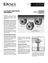
![Download .pdf [3.91MB] - Federal Fluid Power](https://img.yumpu.com/48748421/1/190x245/download-pdf-391mb-federal-fluid-power.jpg?quality=85)
![Download Info Sheet [4.46MB .pdf] - Federal Fluid Power, Inc.](https://img.yumpu.com/47536262/1/190x245/download-info-sheet-446mb-pdf-federal-fluid-power-inc.jpg?quality=85)
![Download Info Sheet [2MB .pdf]](https://img.yumpu.com/41465608/1/184x260/download-info-sheet-2mb-pdf.jpg?quality=85)
![Download .pdf [7.32MB] - Federal Fluid Power, Inc.](https://img.yumpu.com/39318737/1/190x245/download-pdf-732mb-federal-fluid-power-inc.jpg?quality=85)

![Download Info Sheet [430KB .pdf] - Federal Fluid Power, Inc.](https://img.yumpu.com/39314496/1/190x245/download-info-sheet-430kb-pdf-federal-fluid-power-inc.jpg?quality=85)