


7SP300 DIRECTIONAL CONTROL VALVE - Federal Fluid Power, Inc.
7SP300 DIRECTIONAL CONTROL VALVE - Federal Fluid Power, Inc.
7SP300 DIRECTIONAL CONTROL VALVE - Federal Fluid Power, Inc.

Create successful ePaper yourself
Turn your PDF publications into a flip-book with our unique Google optimized e-Paper software.
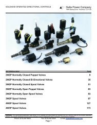
<strong>7SP300</strong><strong>7SP300</strong> <strong>DIRECTIONAL</strong> <strong>CONTROL</strong> <strong>VALVE</strong>2 WAY POPPET • 300 litres/min (80 US GPM) • 210 bar (3000 psi)PILOT SOLENOID CAVITYOMITTED FOR CLARITYNORMALLYOPENNORMALLYCLOSEDINLET 21OUTLETAPPLICATIONTo give on-off control of flows of 300 litres/min (80 USGPM) and pressures up to 210 bar (3000 psi) in anyhydraulic system. Can also be used as a high capacity,fast acting, dump valve.SPECIFICATIONSFigures based on: Oil Temp = 40°C Viscosity = 40 cStRated Flow300 litres/min (80 US GPM)Working Pressure210 bar (3000 psi)11OPERATIONThe normally open or normally closed pilot cartridgecontrols the vent flow through the main poppet. Whenin the open mode, pilot flow passes through the orificein the poppet and the resultant pressure imbalancecauses the main section to open. As the movement ofthe main poppet or spool is not limited by the solenoidstroke, the valves have a flow capacity of 300 litres/min(80 US GPM) with a low pressure drop.Cartridge MaterialBody MaterialMounting PositionWeight (exc. coil)Working parts hardened and groundsteel. External surfaces electrolessnickel plated.AluminiumLine mounted1.90 kg (4.18 lbs)REVERSE PRESSUREThe valves are normally used for the bidirectionalcontrol of flow and the integral check valve ensures thatthe main section will open and pass reverse flowregardless of the pilot mode. The normally closedvalve is typically used in line to an actuator to allow freeflow in and control the flow out.FEATURESThrough port line body construction for readyinstallation into hydraulic lines. Fast resposne, highflow capacity. Cartridge pilot section for easymaintenance. A range of coils is available, see theOrdering Code Example for voltage and terminationoptions.Seal Kit NumberRecommendedFiltration LevelOperating TempLeakageNominal ViscosityRangePilot ValveSK433 (Nitrile)BS5540/4 Class 18/13(25 micron nominal)-20°C to +90°C5 to 500 cStSK433V (Viton)1 millilitre/min max (15 dpm)S203 / S204 (See page 11-141)Integrated Hydraulics LtdIntegrated Hydraulics <strong>Inc</strong>Collins Road, Heathcote Ind. Est., Warwick, CV34 6TF, UK.7047 Spinach Drive, Mentor, Ohio 44060, USATel: +44 (0) 1926 881171 Fax: +44 (0) 1926 315729 Tel: (440) 974 3171 Fax: (440) 974 3170Website: www.integratedhydraulics.comWebsite: www.integratedhydraulics.com11-1351.B
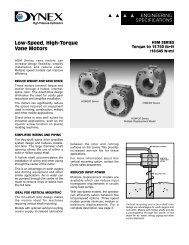
PRESSURE DROPFLOW-US GPM0 2550257520300PRESSURE-BAR1510200PRESSURE-PSI510001002003000FLOW LITRES/MINCOMPLETE <strong>VALVE</strong>3/4” 1” PORTSBASIC CODE: <strong>7SP300</strong>Sub-assembly part numbersBSP, aluminiumSAE, aluminium3/4” CXP3122-6W-S1” CXP3122-8W-S 1” CXP3122-16T-S101.6122.5NORMALLY OPEN119.0NORMALLY CLOSED43.09.595.076.522.017.521SOLENOID CARTRIDGES201 / S202(SEE PAGE 11-1111)71.01192.150.820.028.031.852.063.5Where measurements are critical request certified drawingsORDERING CODE EXAMPLEBasic Code<strong>7SP300</strong> = Complete valveSolenoid Configuration1 = Normally open2 = Normally closedPort Sizes - Bodied Valves Only6W = 3/4” BSP8W = 1” BSP 16T = 1” SAECoil TerminationH = ISO4400 (plug included)F = Flying Leads DC onlyDM = Deutsch MouldedOther terminations available on request<strong>7SP300</strong> 1 6W H 24 SWe reserve the right to change specifications without noticeSealsS= Nitrile (For use with mostindustrial hydraulic oils)SV = Viton (For high temperatureand most special fluidapplications)Coil Voltage12 = 12VDC24 = 24VDC110 = 110VAC 50 Hz220 = 220VAC 50 HzOther voltages availableon request11-1352.B
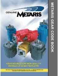
1PUL2001PUL200 PRIORITY UNLOADING <strong>VALVE</strong>PILOT OPERATED - SLIDING SPOOL TYPE1OUTLET (2)DRAIN (3)PILOT (4)4 3INLET (1)2APPLICATIONThese unloader valves are used to divert pump flow toa secondary circuit when pressure in the priority linereaches a pre-set level. The valves will close, causingthe circuit to reload, when the pressure drops toapproximately 85% of the unload pressure. The mostcommon application is to maintain a pressure in anaccumulator which may be used in an emergency tooperate an essential hydraulic function (eg, a brakecircuit). This valve has a drain port to ensure correctvalve function while allowing the bypassed oil to beused for a secondary circuit requirement.SPECIFICATIONSFigures based on: Oil Temp = 40°C Viscosity = 40 cStRated FlowMax SettingDifferentialUnload/ReloadCartridge Material200 litres/min (52 US GPM)350 bar (5000 psi)10-15%All working parts hardened andground steel. External surfaces zincplated12OPERATIONInlet pressure is seen on the nose of the valve andsystem pressure (downstream of the system checkvalve) operates on the system pilot port. Whenpressure rises to the valve setting, the relief sectionopens and the system pressure acts on the pilot pistonto hold the valve in the open position. The ratio betweenthe pilot piston diameter and the seat diameter of therelief valve pilot section ensures that the valve will bemaintained in the fully open position until the systempressure drops to approximately 85% of the unloadpressure.FEATURESBody MaterialMounting PositionCavity NumberTorque Cartridgeinto CavityWeightSeal Kit NumberStandard steelUnrestrictedA3145 (See Section 17)100 Nm (73 lbs ft)1PUL200 0.74 kg (1.63 lbs)1PUL250 6.8 kg (14.96 lbs)1PUL2001PUL250SK670 (Nitrile)SK670V (Viton)SK452 (Nitrile)SK452V (Viton)Valves are available as cartridges for installation intoline bodies or into custom designed HydraulicIntegrated Circuits. (NOTE: Provision must be made fora system check valve and a pilot line to signal thesystem pressure). Valve assemblies can be suppliedcomplete in a line body for ready installation into ahydraulic system. Bodied valves include a check valveand the required connection from the system to thevalve pilot port.RecommendedFiltration LevelOperating TempLeakageNominal ViscosityRangeBS5540/4 Class 18/13(25 micron nominal)-20°C to +90°C35 millilitres/min @ 210 bar5 to 500 cStIntegrated Hydraulics LtdIntegrated Hydraulics <strong>Inc</strong>Collins Road, Heathcote Ind. Est., Warwick, CV34 6TF, UK.7047 Spinach Drive, Mentor, Ohio 44060, USATel: +44 (0) 1926 881171 Fax: +44 (0) 1926 315729 Tel: (440) 974 3171 Fax: (440) 974 3170Website: www.integratedhydraulics.comWebsite: www.integratedhydraulics.com12-121.C
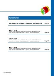
PERFORMANCE CURVETYPICAL <strong>VALVE</strong> PERFORMANCECARTRIDGE ONLYBASIC CODE: 1PUL200SYSTEM WORKING PRESSURE-BAR4003503002502001501005001 2TIME-SECONDS3 456000500040003000200010000SYSTEM WORKING PRESSURE-PSI81.0 49.0 MAXINLET (1)PILOT (4)DRAIN (3)HEX SOCKET ADJUST4.0 A/F17.0 A/F38.1 A/FOUTLET (2)1-5/16-12 UNSCOMPLETE <strong>VALVE</strong>BASIC CODE: 1PUL250Sub-assembly part numbersSAE, aluminium1” BXP23466-16T-S1” PORTS(WITH SYSTEM CHECK)BSP, steel1” BXP23466-8W-S-377SAE, steel1” BXP23466-16T-S-37770.015.042G140.0100.034.0189.0 MAXG 1/4 / 4T122.0 9.013G258.013425.4 9.0 MAX30.0 6.0 MAX50.871.62 HOLES Ø11.0 THRO'101.6Where measurements are critical request certified drawings12ORDERING CODE EXAMPLE1PUL*** P 8W 35 S377Basic Code1PUL200 = Cartridge Only1PUL250 = Cartridge and BodyAdjustment MeansP = Leakproof Screw AdjustmentG = Tamperproof Cap(See page 12-102 for dimensions)Port Sizes - Bodied Valves Only8W = 1” BSP. 1/4” BSP Drain Port16T = 1” SAE. 1/4” SAE Drain PortBody Material377 - SteelOmit for Aluminium (up to 210 bar)SealsS= Nitrile (For use with mostindustrial hydraulic oils)SV = Viton (For high temperature andmost special fluid applications)Adjustable Pressure Range20 = 30-210 bar. Std setting 100 bar35 = 150-350 bar. Std setting 200 barWe reserve the right to change specifications without notice12-122.E
1UL255 TWO PUMP UNLOADING <strong>VALVE</strong>1UL255SYSTEMP2TP112APPLICATIONTwo-pump unloader valves are used in systems withcombinations of two (or more) pumps to give high flowat low pressure and high pressure at low flow. Thevalves bypass the flow from the low pressure pump(s)to tank at a pre-set pressure. This allows pumpselection to give, for example, rapid advance and highpower compaction with the most economic usage ofsystem components and energy requirements.OPERATIONPump inlet to P1 and P2 is combined to give maximumflow at low pressure. When the load pressureincreases to the valve setting the high flow (lowpressure) pump is bypassed from P1 to tank allowingnearly all system power to be used for the highpressure pump. (See graph for the pressure drop ofthe dumped flow). The system relief valve providesprotection by limiting the maximum pressure in thesystem line.FEATURESThis is a self contained system including two replaceablecartridges with full adjustment through their respectiveranges. Hardened working components give long,trouble-free life and single body reduces plumbing to aminimum.SPECIFICATIONSFigures based on: Oil Temp = 40°C Viscosity = 40 cStRated FlowMax SettingCartridge Material150 litres/min (40 US GPM)low flow/high pressure (P2)200 litres/min (52 US GPM)high flow/low pressure (P1)350 bar (5000 psi)All working parts hardened andground steel. External surfaces zincplatedPRESSURE DROPBody MaterialStandard - steel010FLOW-US GPM20 30 40 5060Mounting PositionUnrestrictedPRESSURE-BAR201612840P1 - T50 100 150 200FLOW LITRES/MIN300250200150100500250PRESSURE-PSIWeightSeal Kit NumberRecommendedFiltration LevelOperating TempNominal ViscosityRange3.15 kg (6.93 lbs)SK671 (Nitrile)BS5540/4 Class 18/13(25 micron nominal)-20°C to +90°C5 to 500 cStSK671V (Viton)Integrated Hydraulics LtdIntegrated Hydraulics <strong>Inc</strong>Collins Road, Heathcote Ind. Est., Warwick, CV34 6TF, UK.7047 Spinach Drive, Mentor, Ohio 44060, USATel: +44 (0) 1926 881171 Fax: +44 (0) 1926 315729 Tel: (440) 974 3171 Fax: (440) 974 3170Website: www.integratedhydraulics.comWebsite: www.integratedhydraulics.com12-131.C
COMPLETE <strong>VALVE</strong>BASIC CODE: 1UL255Sub-assembly part numbersBSP, steel3/4” - 1/2” BXP24051-6W-4W-S-377LOW PRESSUREUNLOADING CARTRIDGE1PUL200-P-20-S-JL58.0130.0TP125.4179.0 MAX50.825.410.0110.02 HOLES Ø9.0TP1101.621.0169.0 MAXSYSTEMP226.065.092.0CHECK <strong>VALVE</strong>HIGH PRESSURERELIEF CARTRIDGE1LR100-F-**-S12Basic Code1UL255 = Complete ValveAdjustment MeansP = Leakproof Screw AdjustmentPort Sizes - Bodied Valves Only6W - 4W = 3/4” BSP System, P1 and T. 1/2” BSP P2Adjustable Low Pressure Range20 = 30-210 bar. Std setting 100 bar35 = 150-350 bar. Std setting 200 barWhere measurements are critical request certified drawingsORDERING CODE EXAMPLE1UL255 P 6W- 4W 20 35 SSealsS= Nitrile (For use with mostindustrial hydraulic oils)SV = Viton (For high temperatureand most special fluidapplications)Adjustable High Pressure Range17 = 35-175 bar. Std setting 105 bar28 = 75-285 bar. Std setting 175 bar35 = 114-350 bar. Std setting 280 barWe reserve the right to change specifications without notice12-132.E
CETOP 03 OVERCENTRE STACKING SLICESPILOT ASSISTED RELIEF WITH CHECK03*CE/ 03*CER/ 03*CEB11133314APPLICATIONOvercentre valves give static and dynamic control of loadsby regulating the flow into and out of hydraulic actuators.When installed close to or within an actuator, theovercentre valve will stop runaway in the event of hoseburst and if open centre directional control valves are used,will allow thermal expansion relief of the hydraulic fluid.Single overcentre valves are normally used when the loadis unidirectional, for example an aerial platform or craneand dual overcentre valves are used for controlling loadsin both directions for motor applications or for cylindersgoing over centre.The 1CER series overcentre valve performs all duties of aregular overcentre but is able to relieve and stay openirrespective of downstream pressure. This enables thevalve to operate when used with a closed centre directionalvalve which has service line reliefs. The poppet ispressure balanced, preventing relief setting increase dueto back pressure.--In the 1CEB series pressure balanced overcentre reliefsetting is unaffected by back pressure, enabling the valveto stay open when the valve port pressure rises. This willallow the control of regenerative or meter out proportionalsystems.OPERATIONThe check section allows free flow into the actuator thenholds and locks the load against movement. The pilotassisted relief valve section will give controlled movementwhen pliot pressure is applied. The relief section isnormally set to open at a pressure at least 1.3 times themaximum load induced pressure but the pressurerequired to open the valve and allow movement dependson the pilot ratio of the valve. For optimisation of loadcontrol and energy usage, a choice of pilot ratios isavailable.The pressure required to open the valve and start actuatormovement can be calculated as follows:Pilot Pressure = (Relief Setting) - (Load Pressure)Pilot RatioFEATURESIntegrated Hydraulics Ltd22ATMOSPHERICVENT03*CE 03*CER 03*CEBCartridge is economical and fits simple cavity. Allows quick,easy field service - reduces down time.PILOT RATIOS1CE302.5:1 Best suited for extremely unstable applicationssuch as long booms or flexible frameworks.5:1(Std)SPECIFICATIONSFigures based on: Oil Temp = 40°C Viscosity = 40 cSt2Best suited for applications where load variesand machine structure can induce instability10:1 Best suited for applications where the loadremains relatively constant.1CER304:1 Best suited for applications where the loadremains relatively constant.Other ratios available upon request.1CEB305:1 Best suited for systems where back pressurevaries frequently and for re-generativesystems.Rated FlowMax SettingCartridge MaterialBody MaterialMounting PositionCavity NumberTorque Cartridgeinto CavityWeight(inc Cartridges)Seal Kit NumberRecommendedFiltration LevelOperating TempLeakage30 litres/min (8 US GPM)Max Load InducedPressure: 270 bar (4000 psi)Relief Setting: 350 bar (5000 psi)Working parts hardened and groundsteel. External surfaces zinc platedStandard aluminium (up to 210 bar*)Add suffix ‘377’ for steel optionUnrestrictedA6610 (See Section 17)45 Nm (33 lbs ft)SingleDualSK395 (Nitrile)-20°C to +90°C0.62 kg (1.36 lbs)0.8 kg (1.76 lbs)BS5540/4 Class 18/13(25 micron nominal)Nominal Viscosity5 to 500 cStRangeFor pressure drop curves please see section 6 (cartridgeonly).Integrated Hydraulics <strong>Inc</strong>SK395V (Viton)0.3 millilitres/min nominal (5 dpm)Collins Road, Heathcote Ind. Est., Warwick, CV34 6TF, UK.7047 Spinach Drive, Mentor, Ohio 44060, USATel: +44 (0) 1926 881171 Fax: +44 (0) 1926 315729 Tel: (440) 974 3171 Fax: (440) 974 3170Website: www.integratedhydraulics.comWebsite: www.integratedhydraulics.com14-111.D
COMPLETE <strong>VALVE</strong>BASIC CODE: 03ACE* Overcentre in A, piloted from BSub-assembly part numbersAluminiumBXP9150-SA P T B4 OFF MOUNTING HOLESTA9.8BP47.0 MAX 85.0'X'5.943.5CT1CT148.5A P T BTightening torque of “F” adjusterlocknut - 20 to 25 Nm4 OFF 'O' RINGSBS:1806:012-90'X'SEAL PLATE1.4COMPLETE <strong>VALVE</strong>BASIC CODE: 03BCE* Overcentre in B, piloted from ASub-assembly part numbersAluminiumBXP9150-SA P T B43.55.99.8 4 OFF MOUNTING HOLESTA BP85.047.0 MAX'X'CT148.5CT1A P T BTightening torque of “F” adjusterlocknut - 20 to 25 Nm1.4'X'SEAL PLATE4 OFF 'O' RINGSBS:1806:012-90COMPLETE <strong>VALVE</strong>BASIC CODE: 03ABCE* Overcentre in A & B, cross pilotedSub-assembly part numbersAluminiumBXP9151-SCT1A P T BSteelBXP9151-S-377CT248.5 43.54 OFF MOUNTING HOLES36.0TA BP47.0 MAX110.0 47.0 MAXCT1CT25.5A P T BTightening torque of “F” adjusterlocknut - 20 to 25 Nm4 OFF 'O' RINGSBS:1806:012-90SEAL PLATE1.4FOR SEAL PLATE INFORMATION SEE PAGE 14-151Where measurements are critical request certified drawingsBasic Code03A = Overcentre in A03B = Overcentre in B03AB = Overcentre in A&BOvercentre ValveCE = 1CE30CER = 1CER30CEB = 1CEB30(See Section 6)ORDERING CODE EXAMPLE03 ** CE* F 35 S 4Adjustment MeansF = Screw AdjustmentN = Fixed - State pressure setting requiredFor fixed versions add setting in 10 bar increments to end of partnumber. Subject to a + -10% tolerance.Pressure Range @ 4.8 l/min20 = (All pilot ratios) 70 - 225 bar. Std setting 100 bar (CE)35 = (2.5:1, 4:1, 5:1) 70 - 350 bar. Std setting 210 bar (CE, CER)35 = (10:1) 90 - 350 bar. Std setting 210 bar (CE)35 = (5:1) 75 - 350 bar. Std setting 210 bar (CEB)Other pressure ranges available on requestWe reserve the right to change specifications without noticeBody MaterialOmit = Aluminium. (Up to 210 bar*)377 = Steel.Pilot Ratio2.5:1 (03*CE)4:1 (03*CER)5:1 (03*CE/03*CEB)10:1 (03*CE)SealsS= Nitrile (For use with mostindustrial hydraulic oils)SV = Viton (For high temperature andmost special fluid applications)* For applications above 210 barplease consult our technicaldepartment or use the steel bodyoption.1414-112.B
CETOP 05 OVERCENTRE STACKING SLICESPILOT ASSISTED RELIEF WITH CHECK05*CE/ 05*CER/ 05*CEB111333222ATMOSPHERICVENT05*CE 05*CER 05*CEB14APPLICATIONOvercentre valves give static and dynamic control of loadsby regulating the flow into and out of hydraulic actuators.When installed close to or within an actuator, theovercentre valve will stop runaway in the event of hoseburst and if open centre directional control valves areused, will allow thermal expansion relief of the hydraulicfluid.Single overcentre valves are normally used when theload is unidirectional, for example an aerial platform orcrane and dual overcentre valves are used for controllingloads in both directions for motor applications or forcylinders going over centre.The 1CER series overcentre valve performs all duties ofa regular overcentre but is able to relieve and stay openirrespective of downstream pressure. This enables thevalve to operate when used with a closed centre directionalvalve which has service line reliefs. The poppet ispressure balanced, preventing relief setting increase dueto back pressure.--In the 1CEB series pressure balanced overcentre reliefsetting is unaffected by back pressure, enabling the valveto stay open when the valve port pressure rises. This willallow the control of regenerative or meter out proportionalsystems.OPERATIONThe check section allows free flow into the actuator thenholds and locks the load against movement. The pilotassisted relief valve section will give controlledmovement when pliot pressure is applied. The reliefsection is normally set to open at a pressure at least 1.3times the maximum load induced pressure but thepressure required to open the valve and allow movementdepends on the pilot ratio of the valve. For optimisation ofload control and energy usage, a choice of pilot ratios isavailable.The pressure required to open the valve and startactuator movement can be calculated as follows:Pilot Pressure = (Relief Setting) - (Load Pressure)Pilot RatioFEATURESCartridge is economical and fits simple cavity. Allowsquick, easy field service - reduces down time.PILOT RATIOS4:1 Best suited for applications where the loadremains relatively constant.Other ratios available upon request.SPECIFICATIONSFigures based on: Oil Temp = 40°C Viscosity = 40 cStRated FlowMax SettingCartridge MaterialBody MaterialMounting PositionCavity NumberTorque Cartridgeinto CavityWeight(inc cartridges)Seal Kit Number1CEB Seal Kit NumberRecommendedFiltration LevelOperating TempLeakageNominal ViscosityRange90 litres/min (23 US GPM)Max Load InducedPressure: 270 bar (4000 psi)Relief Setting: 350 bar (5000 psi)Working parts hardened and groundsteel. External surfaces zinc platedStandard aluminium (up to 210 bar*)Add suffix ‘377’ for steel optionUnrestrictedA12336 (See Section 17)60 Nm (44 lbs ft)Single 2.18 kg (4.8 lbs)Dual 3.02 kg (6.64 lbs)SK633 (Nitrile) SK633V (Viton)SK634 (Nitrile) SK634V (Viton)BS5540/4 Class 18/13(25 micron nominal)-20°C to +90°C0.3 millilitres/min nominal (5 dpm)5 to 500 cStFor pressure drop curves please see section 6 (cartridgeonly).Integrated Hydraulics LtdIntegrated Hydraulics <strong>Inc</strong>Collins Road, Heathcote Ind. Est., Warwick, CV34 6TF, UK.7047 Spinach Drive, Mentor, Ohio 44060, USATel: +44 (0) 1926 881171 Fax: +44 (0) 1926 315729 Tel: (440) 974 3171 Fax: (440) 974 3170Website: www.integratedhydraulics.comWebsite: www.integratedhydraulics.com14-121.D
COMPLETE <strong>VALVE</strong>BASIC CODE: 05ACE* Overcentre in A, piloted from BSub-assembly part numbersAluminiumBXP9206-SX TAPBT Y4 OFF MOUNTING HOLES Ø 6.5 THROUGH160.00PXATD.C.V. FACEYBT1.662.00CT1CT11.668.50X TAPBT YTightening torque of “F” adjusterlocknut - 20 to 25 Nm`O'RING PLATEC/W 7 off'`O'RINGS1.40COMPLETE <strong>VALVE</strong>BASIC CODE: 05BCE* Overcentre in B, piloted from ASub-assembly part numbersAluminiumBXP9207-S62.004 OFF MOUNTING HOLES Ø 6.5 THROUGH160.00PXYA BTTX TAPBT Y1.6CT168.501.6CT1X TAPBT YTightening torque of “F” adjusterlocknut - 20 to 25 Nm`O'RING PLATEC/W 7 off `O'RINGS1.40COMPLETE <strong>VALVE</strong>BASIC CODE: 05ABCE* Overcentre in A & B, cross PilotedSub-assembly part numbersAluminiumBXP9209-S62.0 MAX4 OFF MOUNTING HOLESPA BTT200.062.0 MAX62.0TAP BTCT1CT268.5CT1CT2TAPBTTightening torque of “F” adjusterlocknut - 20 to 25 Nm'O' RING PLATEC/W 5 OFF 'O'RINGSBS:1806:015-90SEALPLATE1.4FOR SEAL PLATE INFORMATION SEE PAGE 14-151Where measurements are critical request certified drawingsBasic Code05A = Overcentre in A05B = Overcentre in B05AB = Overcentre in A&BOvercentre ValveCE = 1CE90CER = 1CER90CEB = 1CEB90(See Section 6)Adjustment MeansF = Screw AdjustmentN = Fixed - State pressure setting requiredFor fixed versions add setting in 10 bar increments to endof part number. Subject to a + -10% tolerance.Pressure Range @ 4.8 l/min20 = 70 - 225 bar. Std setting 100 bar35 = 200 - 350 bar. Std setting 210 barStd setting made at 4.8 litres/minOther pressure ranges available on requestORDERING CODE EXAMPLE05 ** CE* F 35 S 4We reserve the right to change specifications without noticeBody MaterialOmit = Aluminium. (Up to 210 bar*)377 = Steel.Pilot Ratio4 = 4:1SealsS= Nitrile (For use with mostindustrial hydraulic oils)SV = Viton (For high temperature andmost special fluid applications)* For applications above 210 barplease consult our technicaldepartment or use the steel bodyoption.1414-122.B
1LR SERIES RELIEF <strong>VALVE</strong>DIRECT ACTING DIFFERENTIAL AREA1LR300POPPET TYPE22PRESSURE (2)TANK (1)1APPLICATIONIdeal for intermittent duty as protection againstoverload or surge conditions for all types of actuators.Very fast acting and extremely dirt tolerant.FEATURESDirt tolerant, robust and consistent with good pressure riseto increase in flow characteristics for a direct acting valve.Cartridge construction provides for maximum flexiblity inmounting at the point where it is most needed.OPERATIONPressure acts over the differentail area between theseat and seal on the poppet. When the pressureexceeds the setting, the valve opens, allowing reliefflow to tank, washing contaminant away from the seat.SPECIFICATIONSFigures based on: Oil Temp = 40°C Viscosity = 40 cStRated FlowMax SettingCartridge Material380 litres/min (100 US GPM)350 bar (5000 psi)Working parts hardened and groundsteel. External surfaces zinc platedPRESSURE DROPBody MaterialStandard aluminium (up to 210 bar*)Add Suffix ‘377’ for steel optionMounting PositionUnrestrictedCavity NumberA1126 (See Section 17)040035025FLOW-US GPM507510060005000Torque Cartridgeinto CavityWeightSeal Kit Number150 Nm (110 lbs ft)1LR300 1.04 kg (2.3 lbs)1LR350 2.08 kg (4.6 lbs)SK207 (Nitrile) SK207V (Viton)PRESSURE-BAR300250200150100400030002000PRESSURE-PSIRecommendedFiltration LevelOperating TempLeakageNominal ViscosityRangeBS5540/4 Class 18/13(25 micron nominal)-20°C to +90°C1 millilitre/min nominal (15 dpm)5 to 500 cSt501000050100 150200250 3003504000FLOW LITRES/MIN*For applications above 210 bar please consult our technical department or use the steel body option.Integrated Hydraulics LtdIntegrated Hydraulics <strong>Inc</strong>Collins Road, Heathcote Ind. Est., Warwick, CV34 6TF, UK.7047 Spinach Drive, Mentor, Ohio 44060, USATel: +44 (0) 1926 881171 Fax: +44 (0) 1926 315729 Tel: (440) 974 3171 Fax: (440) 974 3170Website: www.integratedhydraulics.comWebsite: www.integratedhydraulics.com2-191.C
CARTRIDGE ONLYBASIC CODE: 1LR30070.0 APPROX 10456.4 A/F1-5/8-12 UN-2APRESSURE (2)2TANK (1)Tightening torque of “F” adjusterlocknut - 20 to 25 NmCOMPLETE <strong>VALVE</strong>BASIC CODE: 1LR350Body ONLY part numbersBSP, aluminium1 1/4” B5134SAE, aluminium1 1/4” B77831 1/4’’ PORTSBSP, steel1 1/4” B882SAE, steel1 1/4” B11553208 MAX8.0037.7280.002104.01132.032.065.0063.50Where measurements are critical request certified drawingsORDERING CODE EXAMPLE76.2 2 HOLES DIA 9MM1LR***F10W35SBasic Code1LR300 = Cartridge Only1LR350 = Cartridge and BodyAdjustment MeansF = Screw AdjustmentPort Sizes - Bodied Valves Only10W = 1 1/4’’ BSP 20T = 1 1/4’’ SAESealsS= Nitrile (For use with mostindustrial hydraulic oils)SV = Viton (For high temperatureand most special fluidapplications)Pressure Range @ 30 l/min20 = 35-210 bar. Std setting 100 bar35 = 70-350 bar. Std setting 280 barStd setting made at 30 litres/minWe reserve the right to change specifications without notice2-192.H
1VR SERIES VENTABLE RELIEF <strong>VALVE</strong>PILOT OPERATED1VR200SLIDING SPOOL TYPE21TANK (2)VENT (3)3PRESSURE (1)2APPLICATIONTo limit pressure in a system. Good for continuousduty and accurate pressure control with constant orvarying flows. The vent feature can be used with aremote pilot section for a two-pressure system or toallow manual or remote ‘unloading’ of the pump.SPECIFICATIONSFigures based on: Oil Temp = 40°C Viscosity = 40 cStRated Flow200 litres/min (52 US GPM)Max Setting350 bar (5000 psi)OPERATIONWhen inlet pressure exceeds the setting of the valve,the pilot section opens. The pilot flow causes apressure imbalance across the main section spoolcausing it to open, allowing relief flow to tank. When‘vented’, pilot flow is referenced directly to tank,bypassing the pilot section. This flow through the ventport causes a pressure imbalance, opening the mainsection and dumping the pump at minimum pressuredrop.FEATURESHigh accuracy of pilot operated design. Hardenedworking parts give long, reliable, trouble-free life.Ventible for versatility of application. Cartridgeconstruction for installation into your own manifold.Cartridge MaterialBody MaterialMounting PositionCavity NumberTorque Cartridgeinto CavityWeightSeal Kit NumberRecommendedFiltration LevelOperating TempLeakageNominal ViscosityRangeWorking parts hardened and groundsteel. External surfaces zinc platedStandard aluminium (up to 210 bar*)Add Suffix ‘377’ for steel optionUnrestrictedA16102 (See Section 17)100 Nm (73 lbs ft)1VR200 0.74 kg (1.6 lbs)1VR250 1.82 kg (4.0 lbs)SK173 (Nitrile) SK173V (Viton)BS5540/4 Class 18/13(25 micron nominal)-20°C to +90°C35 millilitres/min @ 280 bar5 to 500 cSt*For applications above 210 bar please consult our technical department or use the steel body option.Integrated Hydraulics LtdIntegrated Hydraulics <strong>Inc</strong>Collins Road, Heathcote Ind. Est., Warwick, CV34 6TF, UK.7047 Spinach Drive, Mentor, Ohio 44060, USATel: +44 (0) 1926 881171 Fax: +44 (0) 1926 315729 Tel: (440) 974 3171 Fax: (440) 974 3170Website: www.integratedhydraulics.comWebsite: www.integratedhydraulics.com2-211.D
PRESSURE DROPFLOW-US GPM0 10 20 30 40 50400606000FLOW-US GPM0 10 20 30 40 5010060PRESSURE-BAR3503002502001505000400030002000PRESSURE-PSIPRESSURE-BAR7550VENTED PRESSURE DROP12501000750500PRESSURE-PSI210050050100150 200FLOW LITRES/MIN2501000025050 100 150 200FLOW LITRES/MIN2502500CARTRIDGE ONLYCOMPLETE <strong>VALVE</strong>1” PORTSBASIC CODE: 1VR200BASIC CODE: 1VR250Body ONLY part numbersBSP, aluminium1” B3496SAE, aluminium1” B6807BSP, steel1” B3497SAE, steel1” B11555HEX SOCKET ADJUST4.0 A/F17.0 A/F81.5 40.5 MAXVENT (3)38.0 A/F1-5/16 -12 UN-2A155.5 MAX115.058.020.0100.02380.0TANK (2)12 HOLESø 9.0 THRO'12.0PRESSURE (1)50.825.444.068.076.2Where measurements are critical request certified drawingsORDERING CODE EXAMPLEBasic Code1VR200 = Cartridge Only1VR250 = Cartridge and BodyAdjustment MeansP = Leakproof Screw AdjustmentG = Tamperproof Cap(See page 2-102 for dimensions)Port Sizes - Bodied Valves Only8W = 1’’ BSP 16T = 1’’ SAE1VR*** P 8W 35 SSealsS= Nitrile (For use with mostindustrial hydraulic oils)SV = Viton (For high temperatureand most special fluidapplications)Pressure Range @ 14 l/min20 = 10-210 bar. Std setting 100 bar35 = 30-350 bar. Std setting 210 barStd setting made at 14 litres/minWe reserve the right to change specifications without notice2-212.D
1CLLR SERIES DUAL RELIEF <strong>VALVE</strong>DIRECT ACTING DIFFERENTIAL AREA1CLLR100POPPET TYPEP1PRESSURE/TANK (2)3PRESSURE/TANK (1)P2APPLICATIONTo protect both lines in a circuit from over pressurisationby relieving oil to the other line. Ideal for use with motorsor directional valves as a safety relief. Differential area,fast acting, poppet valve.OPERATIONPressure acts over one of two differential areas forcingthe poppet back allowing relief flow to the other port.This being a single cartridge is ideal for mounting on tothe motor in a special housing.PRESSURE DROPFEATURESSingle cartridge relieving in both directions cutting downspace requirements, giving full adjustment through itsrange on both pressures at the same time.SPECIFICATIONSFigures based on: Oil Temp = 40°C Viscosity = 40 cStRated FlowMax SettingCartridge MaterialBody Material150 litres/min (40 US GPM)350 bar (5000 psi)Working parts hardened and groundsteel. External steel surfaces black oxideStandard aluminium (up to 210 bar*)Add Suffix ‘377’ for steel optionMounting PositionUnrestrictedFLOW-US GPMCavity NumberA878 (See Section 17)0 10 2040030406000Torque Cartridge intoCavity60 Nm (44 lbs ft)35030025050004000Weight1CLLR1001CLLR1501CLLR1550.23 kg (0.5 lbs)0.8 kg (1.8 lbs)1.1 kg (2.4 lbs)PRESSURE-BAR2001501005003060FLOW LITRES/MIN90 1201503000200010000PRESSURE-PSISeal Kit NumberRecommendedFiltration LevelOperating TempLeakageNominal ViscosityRangeSK614 (Nitrile) SK614V (Viton)BS5540/4 Class 18/13(25 micron nominal)-20°C to +90°C5 millilitres/min5 to 500 cSt*For applications above 210 bar please consult our technical department or use the steel body option.Integrated Hydraulics LtdIntegrated Hydraulics <strong>Inc</strong>Collins Road, Heathcote Ind. Est., Warwick, CV34 6TF, UK.7047 Spinach Drive, Mentor, Ohio 44060, USATel: +44 (0) 1926 881171 Fax: +44 (0) 1926 315729 Tel: (440) 974 3171 Fax: (440) 974 3170Website: www.integratedhydraulics.comWebsite: www.integratedhydraulics.com3-121.D
CARTRIDGE ONLYBASIC CODE: 1CLLR100COMPLETE <strong>VALVE</strong>BASIC CODE: 1CLLR150Body ONLY part numbersBSP, aluminium3/4” B10671” B1069SAE, aluminium3/4” B44091” B108273/4” 1” PORTSBSP, steel3/4” B56141” B542SAE, steel1” B11801HEX SOCKET ADJUST5.0 A/F38.1338.0 67.0 MAX1Tightening torque of “F” adjusterlocknut - 20 to 25 Nm225.4 A/F7/8-14 UNF-2A21.529.450.8134.0 MAX60.325.42273.0112.7 51.076.22 HOLES ø10.5 THRO'COMPLETE <strong>VALVE</strong>BASIC CODE: 1CLLR155Body ONLY part numbersBSP, aluminium3/4” B2216SAE, aluminium3/4” B106232 HOLES ø9.0 THRO'2 298.03/4” PORTSBSP, steel3/4” B7147157.0 MAX72.020.044.51 129.050.813.0 51.076.2Where measurements are critical request certified drawingsORDERING CODE EXAMPLE1CLLR*** F 6W 35 SBasic Code1CLLR100 = Cartridge Only1CLLR150 = Cartridge and Body1CLLR155 = Cartridge and Body through portedAdjustment MeansF = Screw AdjustmentPort Sizes - Bodied Valves Only6W = 3/4’’ BSP 12T = 3/4’’ SAE8W = 1” BSP 16T = 1” SAESealsS= Nitrile (For use with mostindustrial hydraulic oils)SV = Viton (For high temperatureand most special fluidapplications)Pressure Range @ 14 l/min35 = 114-350 bar. Std setting 280 barStd setting made at 14 litres/minWe reserve the right to change specifications without notice3-122.D
1LLR SERIES DUAL RELIEF <strong>VALVE</strong>DIRECT ACTING DIFFERENTIAL AREA1LLR350POPPET TYPEP1P13P2P2THROUGH PRESSURE PORTSAPPLICATIONTo protect directional control valves from shock orsurge pressures induced by changes in direction orsudden stops which create excessive load conditions.OPERATIONThe dual relief is of the cross line type, where exhaustoil from one line is transferred to the other, negatingthe need for a separate tank line. It also preventscavitation when used in conjunction with a closedcentre directional valve. For greatest protection thevalve should be mounted as close to the actuator ormotor as possible.FEATURESSoft start and stop with fast acting operation to givemaximum protection to expensive actuators. Reducesplumbing to a minimum and cartridge construction makesfor easy maintenance.SPECIFICATIONSFigures based on: Oil Temp = 40°C Viscosity = 40 cStRated FlowMax SettingCartridge Material380 litres/min (100 US GPM)350 bar (5000 psi)Working parts hardened and groundsteel. External steel surfaces zinc platedPRESSURE DROPBody MaterialMounting PositionStandard aluminium (up to 210 bar*)Add Suffix ‘377’ for steel optionUnrestrictedPRESSURE-BAR400350300250200150100500 50FLOW-US GPM0 25 50100 150 200FLOW LITRES/MIN75250 300 350Integrated Hydraulics Ltd1004006000500040003000200010000PRESSURE-PSIWeightSeal Kit NumberRecommendedFiltration LevelOperating TempLeakageNominal ViscosityRange5.50 kg (12.0 lbs)SK685 (Nitrile) SK685V (Viton)BS5540/4 Class 18/13(25 micron nominal)-20°C to +90°C1.2 millilitres/min max (20 dpm)5 to 500 cSt*For applications above 210 bar please consult our technical department or use the steel body option.Integrated Hydraulics <strong>Inc</strong>Collins Road, Heathcote Ind. Est., Warwick, CV34 6TF, UK.7047 Spinach Drive, Mentor, Ohio 44060, USATel: +44 (0) 1926 881171 Fax: +44 (0) 1926 315729 Tel: (440) 974 3171 Fax: (440) 974 3170Website: www.integratedhydraulics.comWebsite: www.integratedhydraulics.com3-141.C
COMPLETE <strong>VALVE</strong>BASIC CODE: 1LLR350Sub-assembly part numbersBSP, aluminium1 1/4” BXP24047-10W-SSAE, aluminium1 1/4” BXP24047-20T-S1 1/4” PORTSBSP, steel1 1/4” BXP24047-10W-S-377SAE, steel1 1/4” BXP24047-20T-S-3773108.4152.42 HOLES ø10.0THRO'76.244.416.0P1P137.0P1127.095.290.0P2P2P212.7 127.0360.4 MAX1LR300-F-*-*1LR300-F-*-*Tightening torque of “F” adjusterlocknut - 20 to 25 NmWhere measurements are critical request certified drawingsORDERING CODE EXAMPLE1LLR350 F 10W 20 SBasic Code1LLR350 = Cartridge and BodyAdjustment MeansF = Screw AdjustmentPort Sizes - Bodied Valves Only10W = 1 1/4” BSP 20T = 1 1/4” SAESealsS= Nitrile (For use with mostindustrial hydraulic oils)SV = Viton (For high temperatureand most special fluidapplications)Pressure Range @ 30 l/min20 = 35-210 bar. Std setting 100 bar35 = 70 -350 bar. Std setting 280 barStd setting made at 30 litres/minWe reserve the right to change specifications without notice3-142.H
1DDRC SERIES DUAL RELIEF <strong>VALVE</strong>WITH MAKE UP CHECKS - DIRECT ACTING1DDRC35POPPET TYPEP1P23P1TP2APPLICATIONThis is a dual relief with make up checks. Ideal for useto protect a system where relief volumes are differentsuch as in a single rod cylinder or where leakage maycause cavitation as in the case of motors with a casedrain. It can also be used to protect directional valveswhen they have a closed centre condition.OPERATIONFEATURESSoft start and stop with fast acting operation to givemaximum protection to expensive actuators. Reducesplumbing to a minimum and cartridge construction makesfor easy maintenance.SPECIFICATIONSFigures based on: Oil Temp = 40°C Viscosity = 40 cStThe valve functions as a cross line relief passing oilfrom one line to the other but with an extra tank portwhich allows make up flow or extra exhaust flow totake place.PRESSURE DROPRated FlowMax SettingCartridge Material30 litres/min (8 US GPM)400 bar (5800 psi)Working parts hardened and groundsteel. External steel surfaces zinc plated04002.5FLOW-US GPM57.5105800Body MaterialMounting PositionStandard aluminium (up to 210 bar*)Add Suffix ‘377’ for steel optionUnrestricted3505000Weight1.32 kg (2.904 lbs)PRESSURE-BAR300250200150400030002000PRESSURE-PSISeal Kit NumberRecommendedFiltration LevelOperating TempSK615 (Nitrile) SK615V (Viton)BS5540/4 Class 18/13(25 micron nominal)-20°C to +90°C10050010 20 30FLOW LITRES/MIN4010000LeakageNominal ViscosityRange0.3 millilitres/min max (5 dpm)5 to 500 cSt*For applications above 210 bar please consult our technical department or use the steel body option.Integrated Hydraulics LtdIntegrated Hydraulics <strong>Inc</strong>Collins Road, Heathcote Ind. Est., Warwick, CV34 6TF, UK.7047 Spinach Drive, Mentor, Ohio 44060, USATel: +44 (0) 1926 881171 Fax: +44 (0) 1926 315729 Tel: (440) 974 3171 Fax: (440) 974 3170Website: www.integratedhydraulics.comWebsite: www.integratedhydraulics.com3-151.C
COMPLETE <strong>VALVE</strong>BASIC CODE: 1DDRC35Sub-assembly part numbersBSP, aluminium3/8” BXP21096-3W-SSAE, aluminium3/8” BXP21096-6T-S3/8” PORTSBSP, steel3/8” BXP21096-3W-S-377SAE, steel3/8” BXP21096-6T-S-377314.050.070.0 MAX(DDRC35-*-**40*)52.0 MAX(DDRC35-*-**10/20*)13.058.01DR30-*-*-*P130.0P176.252.0P238.0T90.0 MAXP262.014.033.076.22 HOLES ø7.0 THRO'14.014.0HEX SOCKET ADJUST4.0 A/FWhere measurements are critical request certified drawingsORDERING CODE EXAMPLE1DDRC35 P 3W 40 SBasic Code1DDRC35 = Cartridges and BodyAdjustment MeansP = Leakproof Screw AdjustmentR = Handknob AdjustmentG = Tamperproof CapPort Sizes - Bodied Valves Only3W = 3/8” BSP 6T = 3/8” SAEWe reserve the right to change specifications without noticeSealsS= Nitrile (For use with mostindustrial hydraulic oils)SV = Viton (For high temperatureand most special fluidapplications)Pressure Range @ 4.8 l/min10 = 7-100 bar. Std setting 70 bar20 = 35-210 bar. Std setting 100 bar40 = 50-400 bar. Std setting 280 barStd setting made at 4.8 litres/min3-152.E
1PA SERIES PRESSURE REDUCING <strong>VALVE</strong>PILOT OPERATED1PA200SLIDING SPOOL TYPE2INLET (2)DRAIN (3)3REG (1)15APPLICATIONTo maintain a constant downstream pressure lowerthan the inlet pressure. Ideal for use in two pressuresystems or to protect low pressure actuators such asbrake cylinders. Note: where reverse flow is required,see 1PAA95, page number 5-161.OPERATIONThis valve is normally open, allowing oil from the inletto pass through to the regulated port of the cartridge.When the regulated pressure reaches the valvesetting, the pilot section opens causing a pressureimbalance across the main spool which moves,throttling the inlet flow, preventing any further pressurerise in the regulated line.REGULATED PRESSURE400FLOW-US GPM0 10 20 304050606000FEATURESInternal parts hardened, match ground and honed to givelong, trouble-free life. Pilot style design allows for highflows and accurate performance.SPECIFICATIONSFigures based on: Oil Temp = 40°C Viscosity = 40 cStRated FlowMax SettingBody MaterialMounting Position200 litres/min (52 US GPM)Inlet: 350 bar (5000 psi)Reg: 30-350 bar (435-5000 psi)Max Differential 210 bar (3000 psi) between 1 and 2Cartridge MaterialCavity NumberWorking parts hardened and groundsteel. External surfaces zinc platedStandard aluminium (up to 210 bar*)Add Suffix ‘377’ for steel optionUnrestrictedA16102 (See Section 17)3505000Torque Cartridgeinto Cavity100 Nm (76 lbs ft)3002504000Weight1PA2001PA2500.72 kg (1.59 lbs)1.06 kg (2.34 lbs)PRESSURE-BAR20015010030002000PRESSURE-PSISeal Kit NumberRecommendedFiltration LevelOperating TempSK173 (Nitrile) SK173V (Viton)BS5540/4 Class 18/13(25 micron nominal)-20°C to +90°C501000Pilot Flow550 millilitres/min @ standard setting050100FLOW LITRES/MIN150 200Integrated Hydraulics Ltd2500Nominal ViscosityRange5 to 500 cSt*For applications above 210 bar please consult our technical department or use the steel body option.Integrated Hydraulics <strong>Inc</strong>Collins Road, Heathcote Ind. Est., Warwick, CV34 6TF, UK.7047 Spinach Drive, Mentor, Ohio 44060, USATel: +44 (0) 1926 881171 Fax: +44 (0) 1926 315729 Tel: (440) 974 3171 Fax: (440) 974 3170Website: www.integratedhydraulics.comWebsite: www.integratedhydraulics.com5-141.D
CARTRIDGE ONLYBASIC CODE:1PA200HEX SOCKET ADJUST4.0 A/F80.0 41.0 MAXDRAIN (3)17.0 A/F38.1 A/F1-5/16-12 UNF-2AINLET (2)REG (1)5COMPLETE <strong>VALVE</strong>3/4” 1” PORTSBASIC CODE:1PA250Body ONLY part numbersBSP, aluminium SAE, aluminium3/4” B107861” B3496 1” B6807BSP, steel1” B3497SAE, steel1” B1155550.8156.0 MAX76.232.225.456.0 8.2120.080.0232 HOLES ø8.5 THRO'115.020.058.0Where measurements are critical request certified drawingsBasic Code1PA200 = Cartridge Only1PA250 = Cartridge and BodyAdjustment MeansP = Leakproof Screw AdjustmentR = Handknob AdjustmentG = Tamperproof Cap(See page 5-102 for dimensions)Port Sizes - Bodied Valves Only12T = 3/4” SAE8W = 1” BSP 16T = 1” SAE1/4” BSP Drain Ports 1/4” SAE Drain PortsORDERING CODE EXAMPLE1PA***P 8W 35 SWe reserve the right to change specifications without noticeSealsS= Nitrile (For use with mostindustrial hydraulic oils)SV = Viton (For high temperatureand most special fluidapplications)Pressure Range @ zero flow20 =10-210 bar. Std setting 100 bar35 =30-350 bar. Std setting 280 barStd setting made at zero flow(dead head)5-142.E
1CE SERIES OVERCENTRE <strong>VALVE</strong>PILOT ASSISTED RELIEF WITH CHECK1CE120<strong>VALVE</strong> (2)PILOT (3)1CYL (1)326APPLICATIONOvercentre valves give static and dynamic control ofloads by regulating the flow into and out of hydraulicactuators. When installed close to or within anactuator, the overcentre valve will stop runaway in theevent of hose burst and if open centre directionalcontrol valves are used, will allow thermal expansionrelief of the hydraulic fluid.The overcentre cartridge is ideal for mounting directlyinto a cavity machined in the body of the cylinder, motoror rotary actuator. The cartridge can also be mounteddirectly to the ports via a specifically machined body aspart of a Hydraulic Integrated Circuit or single unit, orcontained within one of our standard line bodies.Single overcentre valves are normally used when theload is unidirectional, for example an aerial platform orcrane and dual overcentre valves are used forcontrolling loads in both directions for motorapplications or for cylinders going over centre.OPERATIONThe check section allows free flow into the actuatorthen holds and locks the load against movement. Thepilot assisted relief valve section will give controlledmovement when pilot pressure is applied. The reliefsection is normally set to open at a pressure at least1.3 times the maximum load induced pressure but thepressure required to open the valve and allow movementdepends on the pilot ratio of the valve. Foroptimisation of load control and energy usage, achoice of pilot ratios is available.The pressure required to open the valve and startactuator movement can be calculated as follows:Pilot Pressure = (Relief Setting) - (Load Pressure)Pilot RatioFEATURESAllows quick, easy field service - reduces down time.Smooth, sure performance.PILOT RATIOS3.5:1 (Standard) Best suited for applications where loadvaries and machine structure caninduce instability.8:1 Best suited for applications where loadremains relatively constant.SPECIFICATIONSFigures based on: Oil Temp = 40°C Viscosity = 40 cStRated FlowMax SettingCartridge MaterialBody MaterialMounting PositionCavity NumberTorque Cartridgeinto CavityWeightSeal Kit NumberRecommendedFiltration LevelOperating TempLeakageNominal ViscosityRange120 litres/min (32 US GPM)Max Load InducedPressure: 270 bar (4000 psi)Relief Setting 350 bar (5000 psi)Working parts hardened and groundsteel. External surfaces zinc platedStandard aluminium (up to 210 bar*)Add suffix ‘377’ for steel optionUnrestrictedA877 (See Section 17)100 Nm (74 lbs ft)1CE1201CE1501CEE150SK417 (Nitrile)-20°C to +90°C5 to 500 cSt0.59 kg ( 1.30 lbs)1.46 kg (3.20 lbs)2.58 kg (5.70 lbs)BS5540/4 Class 18/13(25 micron nominal)SK417V (Viton)0.3 millilitres/min nominal (5 dpm)*For applications above 210 bar please consult our technical department or use the steel body option.Integrated Hydraulics LtdIntegrated Hydraulics <strong>Inc</strong>Collins Road, Heathcote Ind. Est., Warwick, CV34 6TF, UK.7047 Spinach Drive, Mentor, Ohio 44060, USATel: +44 (0) 1926 881171 Fax: +44 (0) 1926 315729 Tel: (440) 974 3171 Fax: (440) 974 3170Website: www.integratedhydraulics.comWebsite: www.integratedhydraulics.com6-181.E
PRESSURE DROPCARTRIDGE ONLY160FLOW-US GPM8 16 243240240BASIC CODE:1CE1204.0 A/F17.0 A/FPRESSURE-BAR1412108642FREE FLOWPILOTED OPEN210180150120906030PRESSURE-PSI59.5 63.0 MAX38.1 A/F1-5/16-12UN-2APILOT (3)<strong>VALVE</strong> (2)0SINGLE <strong>VALVE</strong>BASIC CODE:Body ONLY part numbersBSP, aluminium3/4” B689830 60 90 120FLOW LITRES/MIN1CE150SAE, aluminium3/4” B82001” B107081503/4” 1” PORTSBSP, steel3/4” B55440SAE, steel1” B11814DUAL <strong>VALVE</strong>CYL (1)3/4” PORTSBASIC CODE: 1CEE150 (INTERNALLY CROSS PILOTED)Body ONLY part numbersBSP, aluminium3/4” C2543C1C2SAE, aluminium3/4” C10629BSP, steel3/4” C1200Tightening torque of “F” adjusterlocknut - 20 to 25 NmSAE, steel3/4” C164346V1V251.62 HOLESø10.5 THRO'101.637.076.0 10.6213164.6 MAX112.092.037.0V2C2V1C150.0 8.0175.0 MAX2 HOLESø9.0 THRO'50.825.413.044.083.076.2Where measurements are critical request certified drawings20.682.6101.6Basic Code1CE120 = Cartridge Only1CE150 = Cartridge and Body1CEE150 = Cartridges and BodyAdjustment MeansF = Screw AdjustmentPort Sizes - Bodied Valves Only6W = 3/4” BSP Valve & Cyl Port. 1/4” BSP Pilot Port12T = 3/4” SAE Valve & Cyl Port. 1/4” SAE Pilot Port16T = 1” SAE Valve & Cyl Port. 1/4” SAE Pilot PortPressure Range @ 4.8 l/min35 = 70-350 bar. Std setting 210 barStd setting made at 4.8 litres/minORDERING CODE EXAMPLE1CE**** F 6W 35 S 3We reserve the right to change specifications without noticePilot Ratio3 = 3.5:18 = 8:1SealsS= Nitrile (For use with mostindustrial hydraulic oils)SV = Viton (For high temperatureand most special fluidapplications)6-182.G
1CER SERIES OVERCENTRE <strong>VALVE</strong>PART BALANCED - PILOT ASSISTED1CER140POPPET RELIEF1<strong>VALVE</strong> (2)PILOT (3)3CYL (1)26APPLICATIONThe 1CER series overcentre valve performs all dutiesof a regular overcentre but is able to relieve and stayopen irrespective of downstream pressure. Thisenables the valve to operate when used with a closedcentre directional valve which has service line reliefs.The poppet is pressure balanced, preventing reliefsetting increase due to back pressure.OPERATIONThe check section allows free flow into the actuatorthen holds and locks the load against movement. Thepilot assisted relief valve section will give controlledmovement when pilot pressure is applied. The reliefsection is normally set to open at a pressure at least1.3 times the maximum load induced pressure but thepressure required to open the valve and allowmovement depends on the pilot ratio of the valve. Foroptimisation of load control and energy usage, achoice of pilot ratios is available.The pressure required to open the valve and startactuator movement can be calculated as follows:Pilot Pressure = (Relief Setting) - (Load Pressure)Pilot RatioFEATURESCartridge is economical and fits simple cavity. Allowsquick, easy field service - reduces down time.PILOT RATIOS4:1 Best suited where the load varies andmachine structure can induce instability.6:1 Best suited for applications where the loadremains relatively constant.Other ratios available upon request.SPECIFICATIONSFigures based on: Oil Temp = 40°C Viscosity = 40 cStRated FlowMax SettingCartridge MaterialBody MaterialMounting PositionCavity NumberTorque Cartridgeinto CavityWeightSeal Kit NumberRecommendedFiltration Level140 litres/min (37 US GPM)Max Load InducedPressure: 340 bar (4930 psi)Relief Setting: 420 bar (6090 psi)Working parts hardened and groundsteel. External surfaces zinc platedStandard aluminium (up to 210 bar*)Add suffix ‘377’ for steel optionUnrestrictedA20081150 Nm (110 lbs ft)1CER1401.2 kg (2.6 lbs)1CER145 (aluminium) 2.2 kg (4.8 lbs)1CER145 (steel) 4.0 kg (8.8 lbs)1CEER145 (aluminium) 2.9 kg (6.4 lbs)1CEER145 (steel) 6.0 kg (13.2 lbs)SK1108 (nitrile)BS5540/4 Class 18/13(25 micron nominal)SK1108V (Viton)Operating TempLeakage-20°C to +90°C0.3 millilitres/min nominal (5 dpm)Nominal ViscosityRange5 to 500 cSt*For applications above 210 bar please consult our technical department or use the steel body option.Integrated Hydraulics LtdIntegrated Hydraulics <strong>Inc</strong>Collins Road, Heathcote Ind. Est., Warwick, CV34 6TF, UK.7047 Spinach Drive, Mentor, Ohio 44060, USATel: +44 (0) 1926 881171 Fax: +44 (0) 1926 315729 Tel: (440) 974 3171 Fax: (440) 974 3170Website: www.integratedhydraulics.comWebsite: www.integratedhydraulics.com6-211.D
PRESSURE DROPCARTRIDGE ONLYFLOW-US GPM0 10 20 30 405050725BASIC CODE:1CER1405.00 A/F17.00 A/F4058038.00 A/FPRESSURE-BAR3020PILOT OPEN435290PRESSURE-PSI97.5046.00 A/FM38x2.0100145FREE FLOW040 80 120 160 200FLOW LITRES/MIN72.40CYL (1)PILOT (3)<strong>VALVE</strong> (2)Tightening torque of “F” adjusterlocknut - 20 to 25 NmSINGLE <strong>VALVE</strong>BASIC CODE:Body ONLY part numbersBSP, aluminium3/4” B201051” B201071CER145SAE, aluminium3/4” B119521” B119463/4” 1” PORTSBSP, steel3/4” B201061” B20108SAE, steel3/4” B119531” B11947DUAL <strong>VALVE</strong>1” PORTSBASIC CODE: 1CEER145 (INTERNALLY CROSS PILOTED)Body ONLY part numbersBSP, aluminium SAE, aluminium BSP, steelSAE, steel1” C20285 1” C30105 1” C20287 1” C301066C1C2101.6198.60 MAX12.670.0 CRS21322.0101.6198.6 MAX.46.0V1C1V2C246.0V182.6V231.863.577.590.02 MOUNTING HOLESØ11.0 THROUGH31.863.545.0107.0127.0 CRS152.0Where measurements are critical request certified drawings2 MOUNTING HOLESØ11.0 THROUGHORDERING CODE EXAMPLE1CER*** F 6W 40 S 4Basic Code1CER140 = Cartridge Only1CER145 = Cartridge and Body1CEER145 = Cartridges and BodyAdjustment MeansF = Screw AdjustmentPort Sizes - Bodied Valves Only6W = 3/4” BSP Valve & Cyl Port. 1/4” BSP Pilot Port8W = 1” BSP Valve & Cyl Port. 1/4” BSP Pilot Port16T = 1” SAE Valve & Cyl Port. 1/4” SAE Pilot PortWe reserve the right to change specifications without noticePilot Ratio4 = 4:16 = 6:1Other ratios available upon requestSealsS= Nitrile (For use with mostindustrial hydraulic oils)SV = Viton (For high temperatureand most special fluidapplicationsPressure Range @ 4.8 l/min20 = 140-250 bar. Std setting 190 bar30 = 220-330 bar. Std setting 270 bar40 = 310-420 bar. Std setting 370 barStd setting made at 4.8 litres/min6-212.F
1CEL SERIES OVERCENTRE <strong>VALVE</strong>PILOT ASSISTED RELIEF WITH CHECK AND COUNTERBALANCE1CEL140POPPET RELIEF1<strong>VALVE</strong> (2)PILOT (3)CYL (1)326APPLICATIONThe 1CEL overcentre valve performs all duties of aregular overcentre but maintains a counterbalancepressure to provide dampening to cylinders whenthere is a rapid loss in stored pressure. Thiscounterbalance pressure reduces as the pilotpressure increases. Typical applications includeextension cylinders on telescopic handlers where it isimportant to have a smooth operation when retractingfrom full extension.PILOT RATIOSPrimary 6.1:1Secondary 0.5:1SPECIFICATIONSFigures based on: Oil Temp = 40°C Viscosity = 40 cStRated FlowMax Setting140 litres/min (37 US GPM)380 bar (5510 psi)OPERATIONThe check section allows free flow and then locks theload against movement. The pilot assisted relief valvesection will give controlled movement when pilotpressure is applied, maintaining a counterbalancepressure to prevent initial pressure loss and thereforeinstability. The total pressure setting will normally beset at 1.3 times the load induced pressure. Thecounterbalance pressure reduces as the pilotpressure increases.FEATURESCartridge is economical and fits simple cavity. Allowsquick, easy field service - reduces down time.Cartridge MaterialBody MaterialMounting PositionCavity NumberTorque Cartridgeinto CavityWeightSeal Kit NumberRecommendedFiltration LevelOperating TempLeakageNominal ViscosityRangeWorking parts hardened and groundsteel. External surfaces zinc platedStandard aluminium (up to 210 bar*)Add suffix ‘377’ for steel optionUnrestrictedA20081150 Nm (110 lbs ft)1CEL1401.2 kg (2.6 lbs)1CEL145 (aluminium) 2.2 kg (4.8 lbs)1CEL145 (steel) 4.0 kg (8.8 lbs)1CEEL145 (aluminium) 2.9 kg (6.4 lbs)1CEEL145 (steel) 6.0 kg (13.2 lbs)SK1108 (Nitrile)BS5540/4 Class 18/13(25 micron nominal)-20°C to +90°C5 to 500 cStSK1108V (Viton)0.3 millilitres/min nominal (5 dpm)*For applications above 210 bar please consult our technical department or use the steel body option.Integrated Hydraulics LtdIntegrated Hydraulics <strong>Inc</strong>Collins Road, Heathcote Ind. Est., Warwick, CV34 6TF, UK.7047 Spinach Drive, Mentor, Ohio 44060, USATel: +44 (0) 1926 881171 Fax: +44 (0) 1926 315729 Tel: (440) 974 3171 Fax: (440) 974 3170Website: www.integratedhydraulics.comWebsite: www.integratedhydraulics.com6-225.C
PRESSURE DROPCARTRIDGE ONLYFLOW-US GPM0 10 20 30 405050725BASIC CODE:1CEL1405.00 A/F17.00 A/F4058038.00 A/FPRESSURE-BAR302010PILOT OPENFREE FLOW435290145PRESSURE-PSI97.5072.4046.00 A/FM38x2.0PILOT (3)<strong>VALVE</strong> (2)0SINGLE <strong>VALVE</strong>BASIC CODE:40 80 120 160FLOW LITRES/MIN1CEL145Body ONLY part numbersBSP, aluminium SAE, aluminium3/4” B201051” B20107 1” B1194620003/4” 1” PORTSBSP, steel3/4” B201061” B20108SAE, steel1” B11947DUAL <strong>VALVE</strong>CYL (1)1” PORTSBASIC CODE: 1CEEL145 (INTERNALLY CROSS PILOTED)Body ONLY part numbersBSP, aluminium SAE, aluminium1” C202851” C30105BSP, steel1” C20287Tightening torque of “F” adjusterlocknut - 20 to 25 NmSAE, steel1” C30106 6C1C2101.6198.60 MAX12.670.0 CRS21322.0101.6198.6 MAX46.0V1C1V2C246.0V182.6V231.863.577.590.031.863.545.0107.02 MOUNTING HOLESØ11.0 THROUGH127.0 CRS152.02 MOUNTING HOLESØ11.0 THROUGHThis valve has been designed to eliminate instability from flexible boom applications or where the load inducedpressure varies greatly. To get the best results, the settings should be adjusted for each application and thenfactory set for production quantities. Please contact Integrated Hydraulics for more information.Where measurements are critical request certified drawingsORDERING CODE EXAMPLEBasic Code1CEL140 = Cartridge Only1CEL145 = Cartridge and Body1CEEL145 = Cartridges and BodyAdjustment MeansF = Screw Adjustment1CEL*** F 6W 30 S 220 60Port Sizes - Bodied Valves Only6W = 3/4” BSP Valve & Cyl Port. 1/4” BSP Pilot Port8W = 1” BSP Valve & Cyl Port. 1/4” BSP Pilot Port16T = 1” SAE Valve & Cyl Port. 1/4” SAE Pilot PortWe reserve the right to change specifications without noticeCounterbalance setting bar(10 bar increments).High pressure setting bar(10 bar increments).SealsS= Nitrile (For use with mostindustrial hydraulic oils)SV = Viton (For high temperature andmost special fluid applications)Pressure Range, bar @ 4.8 l/min20 = 170-320. Std 220 (160/60)30 = 230-380. Std 280 (220/60)40 = 310-380. Std 350 (290/60)6-226.D
1CE SERIES OVERCENTRE <strong>VALVE</strong>PILOT ASSISTED RELIEF WITH CHECK1CE3001<strong>VALVE</strong> (2)PILOT (3)3CYL (1)26APPLICATIONOvercentre valves give static and dynamic control ofloads by regulating the flow into and out of hydraulicactuators. When installed close to or within anactuator, the overcentre valve will stop runaway in theevent of hose burst and if open centre directionalcontrol valves are used, will allow thermal expansionrelief of the hydraulic fluid.The overcentre cartridge is ideal for mounting directlyinto a cavity machined in the body of the cylinder, motoror rotary actuator. The cartridge can also be mounteddirectly to the ports via a specifically machined body aspart of a Hydraulic Integrated Circuit or single unit, orcontained within one of our standard line bodies.Single overcentre valves are normally used when theload is unidirectional, for example an aerial platform orcrane and dual overcentre valves are used forcontrolling loads in both directions for motorapplications or for cylinders going over centre.OPERATIONThe check section allows free flow into the actuatorthen holds and locks the load against movement. Thepilot assisted relief valve section will give controlledmovement when pilot pressure is applied. The reliefsection is normally set to open at a pressure at least1.3 times the maximum load induced pressure but thepressure required to open the valve and allow movementdepends on the pilot ratio of the valve. Foroptimisation of load control and energy usage, achoice of pilot ratios is available.The pressure required to open the valve and startactuator movement can be calculated as follows:Pilot Pressure = (Relief Setting) - (Load Pressure)Pilot RatioFEATURESAllows quick, easy field service - reduces down time.Smooth, sure performance.Integrated Hydraulics LtdPILOT RATIOS3:1 (Standard) Best suited for applicationswhere load varies and machinestructure can induce instability.8:1 Best suited for applicationswhere load remains relativelyconstant.SPECIFICATIONSFigures based on: Oil Temp = 40°C Viscosity = 40 cStRated FlowMax SettingCartridge MaterialBody MaterialMounting PositionCavity NumberTorque Cartridgeinto CavityWeightSeal Kit NumberRecommendedFiltration LevelOperating TempLeakageNominal ViscosityRange300 litres/min (80 US GPM)Max Load InducedPressure: 270 bar (4000 psi)Relief Setting 350 bar (5000 psi)Working parts hardened and groundsteel. External surfaces zinc platedStandard aluminium (up to 210 bar*)Add suffix ‘377’ for steel optionUnrestrictedA6935 (See Section 17)150 Nm (110 lbs ft)1CE3001CE3501CEE350SK437 (Nitrile)-20°C to +90°C5 to 500 cSt0.91 kg ( 2.00 lbs)2.71 kg ( 5.96 lbs)5.42 kg (11.92 lbs)BS5540/4 Class 18/13(25 micron nominal)Integrated Hydraulics <strong>Inc</strong>SK437V (Viton)4 millilitres/min nominal (60 dpm)*For applications above 210 bar please consult our technical department or use the steel body option.Collins Road, Heathcote Ind. Est., Warwick, CV34 6TF, UK.7047 Spinach Drive, Mentor, Ohio 44060, USATel: +44 (0) 1926 881171 Fax: +44 (0) 1926 315729 Tel: (440) 974 3171 Fax: (440) 974 3170Website: www.integratedhydraulics.comWebsite: www.integratedhydraulics.com6-241.F
PRESSURE DROPFLOW-US GPM0 25 50 75100CARTRIDGE ONLYBASIC CODE:1CE300HEX SOCKET ADJUST5.0 A/F2435017.0 A/FPRESSURE-BAR21181512963050100 150 200SINGLE <strong>VALVE</strong>BASIC CODE:Body ONLY part numbersBSP, aluminium1 1/4” B6814FLOW LITRES/MIN1CE350SAE, aluminium1 1/4” B10630FREE FLOWPILOT OPEN250 300 350300250200150100500400PRESSURE-PSI1 1/4” PORTSBSP, steel1 1/4” B8610SAE, steel1 1/4” B1147475.5 53.0 MAXDUAL <strong>VALVE</strong>BASIC CODE:Body ONLY part numbersBSP, aluminium1 1/4” C8704CYL (1)PILOT (3)<strong>VALVE</strong> (2)46.0 A/F1-5/8-12 UN-2A1 1/4” PORTS1CEE350 (INTERNALLY CROSS PILOTED)SAE, aluminium1 1/4” C10811BSP, steel1 1/4” C8705Tightening torque of “F” adjusterlocknut - 20 to 25 NmSAE, steel1 1/4” C115646C1C280.08.5V1V22 HOLESØ11.0 THRO'101.623.580.0 10.53249.0154.5 MAX11.080.0101.649.0V1V2154.5 MAX1C1C257.032.031.863.580.0 8.597.097.095.0127.02 HOLES Ø 10.5 THRO'Where measurements are critical request certified drawingsBasic Code1CE300 = Cartridge Only1CE350 = Cartridge and Body1CEE350 = Cartridges and BodyAdjustment MeansF = Screw AdjustmentPort Sizes - Bodied Valves Only10W = 1 1/4” BSP Valve & Cyl Port. 1/4” BSP Pilot Port20T = 1 1/4” SAE Valve & Cyl Port. 1/4” SAE Pilot PortPressure Range @ 4.8 l/min35 = 70-350 bar. Std setting 210 barStd setting made at 4.8 litres/minORDERING CODE EXAMPLE1CE**** F 10W 35 S 3We reserve the right to change specifications without noticePilot Ratio3 = 3:1 (Standard)8 = 8:1SealsS= Nitrile (For use with mostindustrial hydraulic oils)SV = Viton (For high temperatureand most special fluidapplications)6-242.D
1CE SERIES OVERCENTRE <strong>VALVE</strong>ALTERNATIVE BODY ARRANGEMENTS for 300 Litres/min ValvesCOMPLETE <strong>VALVE</strong>BASIC CODE: 1CE356THROUGH PORTED1 1/4” PORTSBody ONLY part numbersBSP, aluminium1 1/4” C13637BSP, steel1 1/4” C13638C1 C1C2 C22 HOLES Ø11.0 THRO'V1 V1V2 V2107.0 10.0101.6V1V1C1105.090.0C2V2120.030.0V2C2648.7598.0127.053.0 MAX1CE300-F35-S*COMPLETE <strong>VALVE</strong>BASIC CODE: 1CEG350GASKET MOUNTED1CE300-F35-S*180.098.049.02322.51 1/4” PORTSSub-assembly part numbersBSP, aluminium1 1/4” CXP20647-10W-SBSP, steel1 1/4” CXP20647-10W-S-37715.91127.047.215.933.433.4 47.24 HOLES Ø15.0 THRO'45.075.5Where measurements are critical request certified drawingsBasic Code1CE356 = Catridge and Body Through Ported1CEG350 = Cartridge and Body Gasket MountedAdjustment MeansF = Screw AdjustmentPort Sizes - Bodied Valves Only10W = 1 1/4” BSP Valve & Cyl Port. 1/4” BSP Pilot PortPressure Range @ 4.8 l/min35 = 70-350 bar. Std setting 210 barStd setting made at 4.8 litres/minORDERING CODE EXAMPLE1CE**** F 10W 35 S 3Pilot Ratio3 = 3:18 = 8:1SealsS= Nitrile (For use with mostindustrial hydraulic oils)SV = Viton (For high temperatureand most special fluidapplications)We reserve the right to change specifications without notice6-269.E
NOTES6
1CEBL SERIES LOAD <strong>CONTROL</strong> / HOLDING <strong>VALVE</strong>c/w Independent Pilot ControlHOSE BURST PROTECTION - SAE FLANGE MOUNTED (REF: ISO 8643)1CEBL556LOADLOADTYPICAL CIRCUITECCT3CT2CT1CT4ECCT3CT2CT1CT4CCT3CT2CT1CT4SERVOPILOTINLET6BLEEDAPPLICATIONVVPILOTDRAINBLEEDThese overcentre valves are suitable for use on theboom and dipper cylinders of an excavator to help themanufacturer or user comply with standard ISO8643.They were designed to give relief, load holding andhose failure protection to systems where a pilotsystem controls the directional valves.OPERATIONBy connecting the hose rupture valve pilot in parallelwith the directional spool valve pilot, and adjusting theopening characteristics of the hose rupture valve tosuit that of the spool valve “BoomLoc” may be set soas not to interfere with the normal operation of themachine. Fine adjustment of the pilot pressurepermits the optimum setting to be made in differingoperating systems.Both the pilot and the relief sections are unaffected bybackpressure, enabling the service line relief’s tooperate normally. In the event of hose failure, thecontrol will be passed from the main spool to the“BoomLoc” valve, maintaining control of the cylinder.Regardless of the load the pilot pressure requirementremains constant as the valve is unaffected by loadinduced pressure, the poppet being fully balanced withzero differential area.FEATURESThis is a compact design with good dirt tolerance.Hardened poppets and seats provide excellent loadholding characteristics with all the advantages of thecartridge insert.VPILDRSPECIFICATIONSFigures based on: Oil Temp = 40°C Viscosity = 40 cStRated FlowMax SettingCartridge MaterialBody MaterialMounting PositionWeightSeal Kit NumberRecommendedFiltration LevelOperating TempLeakageNominal ViscosityRangeV5 to 500 cStPILDRPIL550 litres/min (145 US GPM)400 bar (5800 psi)Working parts hardened and groundsteel. External surfaces electrolessnickel plated and passivatedBright drawn mild steel bar. Zincplated and passivatedFlange mounted21 kg (46.2 lbs)SK1163P (Polyurethane/Nitrile)BS5540/4 Class 18/13(25 micron nominal)-20°C to +90°C4.3 millilitres/min max (70 dpm)Integrated Hydraulics LtdIntegrated Hydraulics <strong>Inc</strong>Collins Road, Heathcote Ind. Est., Warwick, CV34 6TF, UK.7047 Spinach Drive, Mentor, Ohio 44060, USATel: +44 (0) 1926 881171 Fax: +44 (0) 1926 315729 Tel: (440) 974 3171 Fax: (440) 974 3170Website: www.integratedhydraulics.comWebsite: www.integratedhydraulics.com6-431.A
COMPLETE <strong>VALVE</strong>BASIC CODE:1CEBL556FLANGE MOUNTED125.00110.0015.00PILOTCT1125.00110.00BLEEDDRAIN90.00CT21CEBD120-F-40P-12TORQUE TO 100NmSET AT 350 BAR @ 4 L/MIN47APPROX33.3568.0033.3568.0033.3533.351CPBD300-F2PTORQUE TO 150NmSET AT 10 BAR CRACK6220.0064.2515.90 15.90CT3EV68.00140.004 HOLESTAPPED M14 X2.0 X 25.0FULL THREADC33.35 33.3562.5015.9015.90180.004 HOLESØ15.0 THRO'90.00VCT4E15.90 15.9064.25120.00Tightening torque of “F” adjusterlocknut - 20 to 25 NmWhere measurements are critical request certified drawingsORDERING CODE EXAMPLE1CEBL556 F 5/4 6 40 PBasic Code1CEBL556 = Cartridges and BodyAdjustment MeansF = Screw AdjustmentPort Size5/4 = 1 1/4” SAE Flange Cylinder Port1 1/4” SAE Flange Valve Port1/4” BSP All Other PortsSAE Port Type6 = SAE 6000SealsP = Contains polyurethane andstandard seal.Pressure Range @ 4.8 l/min40 = 70-400 bar. Std setting 350 barStd Setting made at 4.8 litres/minWe reserve the right to change specifications without notice6-432.C
2FB SERIES2FB SERIES PRESSURE COMPENSATEDFLOW REGULATOR - BYPASS STYLE1 2REG(2)3INLET (1)TANK (3)9APPLICATION2FB valves are bypass flow regulators. The flow (andactuator speed) will be largely independent of the loadand the pressure conditions.If used to regulate flow from a fixed supply, for examplea standard gear or piston pump, the valve will pass therequired flow and any surplus flow will be dumped tothe tank line at working pressure. The supply pressurerequirement will be approximately 7 bar (100 psi)higher than the system pressure, this being theoperating pressure of the valve.SPECIFICATIONSFigures based on: Oil Temp = 40°C Viscosity = 40 cStRated FlowINLET:2FB25 55 litres/min (14 US GPM)2FB55 95 litres/min (25 US GPM)2FB95 150 litres/min (40 US GPM)2FB195 285 litres/min (70 US GPM)REGULATED:2FB25 30 litres/min ( 8 US GPM)2FB55 55 litres/min (14 US GPM)2FB95 95 litres/min (25 US GPM)2FB195 195 litres/min (50 US GPM)OPERATIONInlet flow passes through the adjustable orifice and outof the regulated port. The pressure drop across theorifice is sensed at each end of the spool, producing aforce which, at the required flow rate, overcomes thespring force. The resultant movement of the spoolregulates the flow by opening the radial valve ports anddumping excess flow.The valve will pass flow in the return direction but thisis restricted by the flow path through the control orifice.For correct valve function the pressure on the tank lineMUST be lower than the minimum pressure on theregulated line.FEATURESLine body construction allows direct connection intohydraulic systems. Leakproof adjust screw gives easy,accurate adjustment to required flow setting. Hardenedand ground working parts give accurate flowcontrol and long working life.Max PressureMaterialBody MaterialMounting PositionWeightSeal Kit NumberRecommendedFiltration LevelOperating TempNominal ViscosityRange210 bar (3000 psi)All working parts hardened, groundand honed steelStandard aluminium (up to 210 bar)Add suffix ‘377’ for steel optionLine mounted2FB25/2FB552FB952FB1952FB25/552FB952FB195BS5540/4 Class 18/13(25 micron nominal)-20°C to +90°C5 to 500 cSt0.79 kg (1.74 lbs)0.82 kg (1.80 lbs)1.57 kg (3.46 lbs)SK355 (Nitrile)SK355V (Viton)SK661 (Nitrile)SK661V (Viton)SK374 (Nitrile)SK374V (Viton)*For applications above 210 bar please consult our technical department or use the steel body option.Integrated Hydraulics LtdIntegrated Hydraulics <strong>Inc</strong>Collins Road, Heathcote Ind. Est., Warwick, CV34 6TF, UK.7047 Spinach Drive, Mentor, Ohio 44060, USATel: +44 (0) 1926 881171 Fax: +44 (0) 1926 315729 Tel: (440) 974 3171 Fax: (440) 974 3170Website: www.integratedhydraulics.comWebsite: www.integratedhydraulics.com9-151.C
REGULATED FLOW-LITRES/MIN0 700 1400100LOAD PRESSURE-PSI2100 2800 3500252FB552FB25207515501025500 50 100 150 200 250LOAD PRESSURE-BARREGULATED FLOW-US GPMPERFORMANCEREGULATED FLOW-LITRES/MIN200150100LOAD PRESSURE-PSI0 700 14002100 2800 35002FB195522FB95392650130 50 100 150 200 250 0LOAD PRESSURE-BARREGULATED FLOW-US GPMCOMPLETE <strong>VALVE</strong>ODC21GM LP3NKH9FBAEBasic CodePort SizeABCDEFGHKLMNOP2FB252FB552FB952FB1953/8”1/2”3/4”1”82.582.595105383838517676761021111111111371101101231434646576157575777.519191925.59.59.516139.59.59.51057575782.563.563.570799910.510.528.528.53038Where measurements are critical request certified drawingsORDERING CODE EXAMPLEBasic Code2FB = Complete ValveAdjustment MeansP = Leakproof Screw AdjustmentR = Handknob AdjustmentD = Detent Adjustment (2FB95 only)L = Lever Adjustment (2FB95 only)(See page 9-102 for dimensions)Port Sizes - Bodied Valves Only3W = 3/8” BSP 6T = 3/8” SAE4W = 1/2” BSP 8T = 1/2” SAE6W = 3/4” BSP 12T = 3/4” SAE8W = 1” BSP 16T = 1” SAE2FB** P 6W 95We reserve the right to change specifications without noticeSSealsS= Nitrile (For use with mostindustrial hydraulic oils)SV = Viton (For high temperature andmost special fluid applications)Adjustable Flow Range25 = 0- 30 litres/min - 2FB2555 = 0- 55 litres/min - 2FB5595 = 0- 95 litres/min - 2FB95195 = 0-195 litres/min - 2FB1959-152.D
2FP SERIES2FP SERIES PRESSURE COMPENSATEDFLOW REGULATOR - PRIORITY STYLE1 2INLET (1)3BYPASS (3) REG (2)9APPLICATION2FP valves are priority flow regulators. The flow (andactuator speed) will be largely independent of the loadand the pressure conditions.If used to regulate flow from a fixed supply, for examplea standard gear or piston pump, the valve will pass therequired flow and any surplus flow will be diverted tothe bypass port. The bypass flow may be used for asecondary circuit whether the secondary pressurerequirement is higher or lower than the regulatedpressure.The valve inlet pressure will be approximately 7 bar(100 psi) more than the regulated or bypass pressure,whichever is higher.OPERATIONInlet flow passes through the adjustable orifice and theradial holes in the spool/sleeve assembly then out ofthe regulated port. The pressure drop across theorifice is sensed at each end of the spool, producing aforce which, at the required flow rate, overcomes thespring force. The resultant movement of the spoolregulates the flow by opening the radial valve ports tothe bypass port and closing the regulated flow ports.SPECIFICATIONSFigures based on: Oil Temp = 40°C Viscosity = 40 cStRated FlowMax PressureMaterialBody MaterialMounting PositionWeightINLET:2FP25 55 litres/min ( 14 US GPM)2FP55 95 litres/min ( 25 US GPM)2FP95 150 litres/min ( 40 US GPM)2FP195 380 litres/min (100 US GPM)2FPX5444 380 litres/min (100 US GPM)REGULATED:2FP25 30 litres/min ( 8 US GPM)2FP55 55 litres/min (14 US GPM)2FP95 95 litres/min (25 US GPM)2FP195 160 litres/min (42 US GPM)2FPX5444 160 litres/min (42 US GPM)2FP25/55/95/1952FPX5444Line mounted210 bar (3000 psi)350 bar (5000 psi)All working parts hardened andground steelStandard aluminium (up to 210 bar*)Add suffix ‘377’ for steel option2FP25/2FP55 0.99 kg ( 2.20 lbs)2FP95 1.83 kg ( 4.03 lbs)2FP195 3.77 kg ( 8.30 lbs)2FPX5444 10.79 kg (23.75 lbs)The valve will pass flow in the return direction but thisis restricted by the flow path through the control orifice.FEATURESLine body construction with three ports allows directconnection into hydraulic systems. Leakproof adjustscrew gives easy, accurate adjustment to required flowsetting. Hardened and ground working parts giveaccurate flow control and long working life.*For applications above 210 bar please consult ourtechnical department or use the steel body option.Seal Kit NumberRecommendedFiltration LevelOperating TempNominal ViscosityRange2FP25/552FP952FP195BS5540/4 Class 18/13(25 micron nominal)-20°C to +90°C5 to 500 cStSK192 (Nitrile)SK192V (Viton)SK222 (Nitrile)SK222V (Viton)SK412 (Nitrile)SK412V (Viton)Integrated Hydraulics LtdIntegrated Hydraulics <strong>Inc</strong>Collins Road, Heathcote Ind. Est., Warwick, CV34 6TF, UK.7047 Spinach Drive, Mentor, Ohio 44060, USATel: +44 (0) 1926 881171 Fax: +44 (0) 1926 315729 Tel: (440) 974 3171 Fax: (440) 974 3170Website: www.integratedhydraulics.comWebsite: www.integratedhydraulics.com9-171.E
PERFORMANCEREGULATED FLOW-LITRES/MIN655545352515LOAD PRESSURE-PSIBYPASS HIGHER THAN REGULATED HIGHER THANREGULATED PRESSURE BYPASS PRESSURE2800 2100 1400 700 0 700 1400 2100 28002FP552FP251512.5107.55.02.5REGULATED FLOW-US GPMREGULATED FLOW-LITRES/MINLOAD PRESSURE-PSIBYPASS HIGHER THANREGULATED HIGHER THANREGULATED PRESSUREBYPASS PRESSURE2800 2100 1400 700 0 700 1400 2100 28002902FP195/2FPX54442FP95235165115606552392613REGULATED FLOW-US GPM0200150100 50 0 50 100 150 200LOAD PRESSURE-BAR00200150100 50 0 50 100LOAD PRESSURE-BAR1502000COMPLETE <strong>VALVE</strong>KNOMCD1LF3GA2HBP9EBasic Code2FP252FP552FP952FP1952FPX5444Port Size3/8”1/2”3/4”1”1”A127130152.5146152B38385163.563.5C63.563.576127133D9999111162168E165168190202242F44.547.554.54148G82.585.510099105H191925.53232K9.512.581313L9.59.581313M44.544.560101.5108N108108136.5120.5127O9910.510.513.5P28.528.5326766.5Where measurements are critical request certified drawingsORDERING CODE EXAMPLEBasic Code2FP = Complete ValveAdjustment MeansP = Leakproof Screw AdjustmentR = Handknob AdjustmentD = Detent Adjustment (2FP95 only)L = Lever Adjustment (2FP95 only)(See page 9-102 for dimensions)Port Sizes - Bodied Valves Only3W = 3/8” BSP 6T = 3/8” SAE4W = 1/2” BSP 8T = 1/2” SAE6W = 3/4” BSP 12T = 3/4” SAE8W = 1” BSP 16T = 1” SAE2FP**P6W95SSealsS= Nitrile (For use with mostindustrial hydraulic oils)SV = Viton (For high temperature andmost special fluid applications)Adjustable Flow Range25 = 0- 30 litres/min - 2FP2555 = 0- 55 litres/min - 2FP5595 = 0- 95 litres/min - 2FP95195 = 0-195 litres/min - 2FP195/2FPX5444We reserve the right to change specifications without notice9-172.E
![Download Info Sheet [14MB .pdf] - Federal Fluid Power](https://img.yumpu.com/50820508/1/190x245/download-info-sheet-14mb-pdf-federal-fluid-power.jpg?quality=85)
![Download .pdf [3.91MB] - Federal Fluid Power](https://img.yumpu.com/48748421/1/190x245/download-pdf-391mb-federal-fluid-power.jpg?quality=85)
![Download Info Sheet [4.46MB .pdf] - Federal Fluid Power, Inc.](https://img.yumpu.com/47536262/1/190x245/download-info-sheet-446mb-pdf-federal-fluid-power-inc.jpg?quality=85)
![Download Info Sheet [2MB .pdf]](https://img.yumpu.com/41465608/1/184x260/download-info-sheet-2mb-pdf.jpg?quality=85)
![Download .pdf [7.32MB] - Federal Fluid Power, Inc.](https://img.yumpu.com/39318737/1/190x245/download-pdf-732mb-federal-fluid-power-inc.jpg?quality=85)
![Download Info Sheet [430KB .pdf] - Federal Fluid Power, Inc.](https://img.yumpu.com/39314496/1/190x245/download-info-sheet-430kb-pdf-federal-fluid-power-inc.jpg?quality=85)