

Low-Speed, High-Torque Vane Motors - Federal Fluid Power, Inc.
Low-Speed, High-Torque Vane Motors - Federal Fluid Power, Inc.
Low-Speed, High-Torque Vane Motors - Federal Fluid Power, Inc.
- No tags were found...

You also want an ePaper? Increase the reach of your titles
YUMPU automatically turns print PDFs into web optimized ePapers that Google loves.
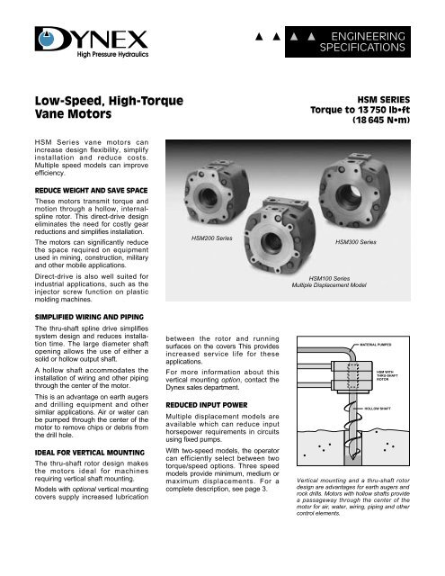
DYNEX<strong>High</strong> Pressure HydraulicsENGINEERINGSPECIFICATIONS<strong>Low</strong>-<strong>Speed</strong>, <strong>High</strong>-<strong>Torque</strong><strong>Vane</strong> <strong>Motors</strong>HSM SERIES<strong>Torque</strong> to 13 750 lb•ft(18 645 N•m)HSM Series vane motors canincrease design flexibility, simplifyinstallation and reduce costs.Multiple speed models can improveefficiency.REDUCE WEIGHT AND SAVE SPACEThese motors transmit torque andmotion through a hollow, internalsplinerotor. This direct-drive designeliminates the need for costly gearreductions and simplifies installation.The motors can significantly reducethe space required on equipmentused in mining, construction, militaryand other mobile applications.Direct-drive is also well suited forindustrial applications, such as theinjector screw function on plasticmolding machines.SIMPLIFIED WIRING AND PIPINGThe thru-shaft spline drive simplifiessystem design and reduces installationtime. The large diameter shaftopening allows the use of either asolid or hollow output shaft.A hollow shaft accommodates theinstallation of wiring and other pipingthrough the center of the motor.This is an advantage on earth augersand drilling equipment and othersimilar applications. Air or water canbe pumped through the center of themotor to remove chips or debris fromthe drill hole.IDEAL FOR VERTICAL MOUNTINGThe thru-shaft rotor design makesthe motors ideal for machinesrequiring vertical shaft mounting.Models with optional vertical mountingcovers supply increased lubricationHSM200 Seriesbetween the rotor and runningsurfaces on the covers This providesincreased service life for theseapplications.For more information about thisvertical mounting option, contact theDynex sales department.REDUCED INPUT POWERMultiple displacement models areavailable which can reduce inputhorsepower requirements in circuitsusing fixed pumps.With two-speed models, the operatorcan efficiently select between twotorque/speed options. Three speedmodels provide minimum, medium ormaximum displacements. For acomplete description, see page 3.HSM300 SeriesHSM100 SeriesMultiple Displacement ModelMATERIAL PUMPEDHSM WITHTHRU-SHAFTROTORHOLLOW SHAFTVertical mounting and a thru-shaft rotordesign are advantages for earth augers androck drills. <strong>Motors</strong> with hollow shafts providea passageway through the center of themotor for air, water, wiring, piping and othercontrol elements.
Efficient, Long-LifeMotor OperationEFFICIENT LONG-LIFE OPERATIONHSM motors deliver smooth rotarypower from stall to maximum speeds.A radially balanced design improvesmechanical efficiency and extendsoperating life.A unique square profile producesextra strength at the corners forextended fatigue life, especially athigh pressures.THERMAL SHOCK PROTECTIONOptional warm-up ports in HSMSeries motors can reduce thepotential for motor seizure caused bythermal shock.Thermal shock is caused by introducingwarmer fluid, from a workingportion of a circuit, into a coolermotor. A temperature differenceapproaching 50° F (10° C) can resultin uneven expansion of internal componentscausing motor seizure.Warm-up ports reduce the potentialfor shock by allowing fluid to becirculated through the motor withoutrotor rotation, equalizing fluid andmotor temperatures. This feature isespecially beneficial for mobileequipment used in cold weather.For information on this optioncontact your Dynex representative.HSM MOTORTAPBFLOW FROM ANAUXILIARY PUMPOR ANOTHERMACHINE CIRCUITWarm-up ports in the motor covers preventmotor seizure caused by thermal shock.RUNNING SURFACE SLOTSSlots carry fluid to and frommotor ports to cam “lobes”DOUBLE OUTLET COVEROptional multiple speed modelsreduce input horsepowerRADIALLY BALANCED DESIGNFor superior mechanical efficiencyand extended operating lifeUNIQUE “SQUARE” PROFILEExtra strength at corners extendsfatigue life at high pressuresCAM RINGRing contours form diametricallybalanced ramps, or “lobes”THRU-SHAFT ROTOR DESIGNPermits hollow shaft for simplifiedsystem design and installationHSM100 Series Multiple Displacement Motor2
Single and Multiple<strong>Speed</strong> OperationHSM Series motors utilize a slottedrotor with 18 vanes that move radiallyagainst a cam ring. As the rotorturns, the vanes ride on the ring andslide in and out of the slots.The ring contours form four majorand four minor radial sections, joinedby transitional ramps, or lobes.Pressurized fluid is delivered to thelobes through slots in the coverrunning surface.MULTIPLE SPEED MODELSIn circuits using fixed displacementpumps, multiple speed/torquemodels can reduce input horsepowerrequirements.With two-speed models, the operatorcan select either full torque at normalspeed, or double speed at half thetorque. These models utilize a twoport cover, with each port independentlyconnected to a separate set ofdiametrically opposed lobes of equaldisplacement.Three-speed models offer greaterflexibility. The operator selects eitherminimum, medium or maximum displacement(with speed and torquedetermined by the specific model).These models also use a two-portcover, with a “split-rise” cam providingunequal displacements. In atypical circuit, shown below, aselector valve directs fluid to andfrom the motor ports to determinewhich pair of lobes will bepressurized.PRESSURE BALANCED VANESCAM RINGSingle-PortCover (C Port)HSM SERIES MOTORCATwo-PortCover (A & B Port)BFullDisplacementLOBESCam ring contours form diametricallybalanced ramps or “lobes”. This radiallybalanced design provides superiormechanical efficiency and extended life.MediumDisplacementMinimumDisplacementDISPLACEMENTSELECTORSINGLE SPEED MODELSIn single speed models, a port ineach motor cover connects to twosets of diametrically opposed and balancedlobes. <strong>Fluid</strong> entering the port inone cover causes the rotor to turn.Movement of the rotor transports fluidto the slots connected to the otherport, to return to tank. As the rotorturns, it drives the shaft which isspline connected to the rotor.The direction of rotation is determinedby which of the two ports arepressurized.ClockwiseRotationCounter-ClockwiseRotationDIRECTIONALVALVETypical three-speed motor circuit uses a displacement selector valve which directs fluid to andfrom the motor ports to determine the speed and torque combination. The direction of rotationis determined by the other directional valve in the circuit. This circuit is shown for referenceonly. Other circuit arrangements are possible and may be more beneficial depending on thespecific application.3
SPECIFICATIONSSingleDisplacementModel NumberInput Flow, Maximum <strong>Speed</strong> MaximumTheoretical <strong>Torque</strong>Multiple Displacement <strong>Torque</strong> Splits ➀Multiple100 rpm at 2000 psi PressureDisplacementlblb • ft per 100 psi N • m per 10 bar(140 bar) at Stall• ft per N • m perModel Number100 psi 10 barPort A Port B Port A Port B U.S. gpm L/min rpm psi barHSM100-2493 70 138 HSM100-2522 35 35 69 69 28.0 106,0 300 4000 280HSM100-2454 90 177 HSM100-2455 45 45 88 88 38.0 143,8 300 4000 280HSM200-2696 130 256 HSM200-2700 75 55 147 108 48.0 181,7 250 3000 210HSM200-2695 150 295 HSM200-2699 75 75 147 147 55.0 208,2 250 3000 210HSM300-2598 190 374 HSM300-2590 95 95 187 187 70.0 265,0 200 2750 190HSM300-2601 220 433 HSM300-2591 125 95 246 187 80.0 302,8 150 2750 190HSM300-2521 250 492 HSM300-2579 125 125 246 246 91.0 344,4 150 2750 190HSM300-2592 380 747 HSM300-2594 190 190 374 374 140.0 529,9 200 2750 190HSM300-2602 440 865 HSM300-2595 250 190 492 374 158.0 598,0 150 2750 190HSM300-2551 500 983 HSM300-2597 250 250 492 492 184.0 696,4 150 2750 190➀ Multiple displacement models use a two-port cover (Port A and Port B). Models with equal torque splits provide two speed/torque selection. Models withunequal torque splits provide three speed/torque selection when used in a typical circuit as shown on page 3.Installation andPerformance DataSELECTING HSM MODELSThe table above shows single andmultiple speed models.The larger size HSM300 motorslisted are double rotor models. Toselect these models, see performancecurves on page 7 andinstallation drawings on page 8.For information on optional warm-upports and a review of your application,contact your Dynex representative.DIMENSIONS AND CURVESPerformance curves on the followingpages are typical and are based on100 SUS (20 cSt) petroleum-basedfluid at 120° F (50° C). Dimensionsare shown in inches (millimeters inparentheses) and are nominal values.INSTALLATIONHSM Series motors must be operatedunder a loaded condition, 150 psi(11 bar) minimum.The table at right shows spline data.Units must have a slip fit betweenshaft and rotor splines with no axialforce or binding. Axial movement ofthe shaft, under load, is not permitted.Drive shaft must be concentric tomotor pilot diameter within 0.004 inch(0,1 mm) TIR. Mounting surfaceshould be flat within 0.001 inch(0,03 mm) and perpendicular to motoraxis within 0.001inch (0,03 mm)TIR.Shaft design must provide forretention of grease as the spline isnot lubricated by system fluid.OPERATING RECOMMENDATIONSStandard Seals Buna-N (Nitrile)<strong>Fluid</strong><strong>High</strong>-grade premium petroleum-basedoil, with a combination of anti-wear,demulsibility, rust protection, andoxidation resistance and foam resistanceproperties.See table right, below, for fluidspecifications.Minimum Filtration Levels25 µ nominal;Consistent with recommendedhydraulic practice, finer filtrationlevels than these are desirable andwill result in longer component life.SPLINE DATAInternal andExternalInvoluteSplineHSM Motor Series100 200 300Fillet Root Side Fit Side Fit Side FitNo. of Teeth 39 40 48DiametricalPitch12/24 10/20 10/20PressureAngle30° 30° 30°Major DiameterInternal3.4130 4.1950 4.9950(Rotor)3.4000 4.1800 4.9800Major DiameterExternal(Shaft)3.3333 4.1000 4.90003.3283 4.0950 4.8950MountingModels in the table are designed forhorizontal mounting. For vertical shaftmounting, models are available thatsupply increased lubrication betweenthe rotor and the running surfaces.For specific model numbers, contactthe Dynex sales department.Case Drain PressureMaximum 25 psig (1,7 bar)Start-UpFill motor through any cover portprior to start-up.Weight (Mass)HSM 100: 230 lb (104 kg);HSM 200: 315 lb (143 kg);HSM 300:Single Rotor, 460 lb (209 kg);Double Rotor, 630 lb (286 kg)FLUID SPECIFICATIONS ➀Specification<strong>Fluid</strong> GradeSummer ➁ Winter ➂Viscosity at150-300 SUS 75-200 SUS100° F .(37,8° C)(38,3-64,9 cSt) (14,4-43,1 cSt)Viscosity at 43 SUS 43 SUS210° F (5,2 cSt) (5,2 cSt)(98,9° C) Minimum MinimumPour Point, 0° FTypical (-17,8° C)-40° F(-40° C)or LessViscosity 95 95Index Minimum Minimum➀ If fluid conditions fall outside of the rangeshown, consult the Dynex sales department.➁ Warm Weather Grade, Above +40° F (4,4° C)➂ Cold Weather Grade, Below +40° F (4,4° C)4
HSM100 PERFORMANCE AND INSTALLATIONN • MLB • INHSM 10070 LB • FT / 100 PSI (138 N • M / 10 BAR)HSM 10090 LB • FT / 100 PSI (177 N • M / 10 BAR)U.S.GPML/MIN.OUTPUT TORQUE350030002500200015001000500300002500020000150001000050003000 PSI, 210 BAR2500 PSI, 175 BAR2000 PSI, 140 BAR1500 PSI, 105 BAR1000 PSI, 70 BAR500 PSI, 35 BAR3000 PSI, 210 BAR2500 PSI, 175 BAR2000 PSI, 140 BAR1500 PSI, 105 BAR500 PSI, 35 BAR1000 PSI, 70 BAR12010080604020500400300200100INPUT VOLUME (DOTTED LINE)0060 120 180 240 300 60 120 180 240 300SPEED – RPMSPEED – RPM0SUPPLY PORT "A"PATTERN FOR STANDARD1-1/4 INCH S.A.E.4-BOLT FLANGE8.50(215,9)4.25(108,0)2.535(64,39)2.535(64,39).65(16,5)SUPPLY PORT "B"PATTERN FOR STANDARD1-1/4 INCH S.A.E.4-BOLT FLANGEOF 4-BOLTLcFLANGESUPPLY PORT "C"PATTERN FOR STANDARD1-1/2 INCH S.A.E.4-BOLT FLANGE5.52(140,2)1.75(44,4)OF 4-BOLTLcFLANGESQUARE KEY.625 x 2.50 (15,88 x 63,5)SUPPLY PORTS (2)PATTERN FOR STANDARD1-1/2 INCH S.A.E.4-BOLT FLANGE5.39(136,9)OF 4-BOLTLcFLANGEOF 4-BOLTLcFLANGE2.7732.76870,43( 70,32 )2.4982.49763,45( 63,42 )3.9503.750100,33( 95,25 )11.94(303,3)1.75(44,4)6 MTG. HOLES.625-11 UNC–2B THD.2.25 (57,2) DEEP7.38(187,5)3.69(93,7)1.84(46,7)2.09 (53,1)FULL SPLINE LENGTH6.25(158,8).875(22,22)13.50(342,9) 60°15° 15°9.03(229,4)10.500(266,70)60°5.97(151,6)4.4244.412112,37( 112,06 )4.3322 .0984.3307 (2,49)110,038(110,000)1.197 30,401.169( 29,69 )2.91(73,9)8.91(226,3)2.91(73,9)DRAIN PORTS (2)NO. 6 S.A.E.3.50(88,9)5
HSM200 PERFORMANCE AND INSTALLATIONN • MLB • INHSM 200130 LB • FT / 100 PSI (256 N • M / 10 BAR)HSM 200150 LB • FT / 100 PSI (295 N • M / 10 BAR)3000 PSI, 210 BARU.S.GPML/MIN.OUTPUT TORQUE50004000300020001000400003000020000100003000 PSI, 210 BAR2500 PSI, 175 BAR2000 PSI, 140 BAR1500 PSI, 105 BAR1000 PSI, 70 BAR500 PSI, 35 BAR2500 PSI, 175 BAR2000 PSI, 140 BAR1500 PSI, 105 BAR1000 PSI, 70 BAR500 PSI, 35 BAR120906030500400300200100INPUT VOLUME (DOTTED LINE)0050 100 150 200 250 50 100 150 200 250SPEED – RPMSPEED – RPM0SUPPLY PORT "A"PATTERN FOR STANDARD1-1/2 INCH S.A.E.4-BOLT FLANGE4.94(125,4)2.840(72,14)9.875(250,8)2.840(72,14).781(19,84)SUPPLY PORT "B"PATTERN FOR STANDARD1-1/2 INCH S.A.E.4-BOLT FLANGELcOF 4-BOLTFLANGE6.329(160,75)SUPPLY PORT "C"PATTERN FOR STANDARD2 INCH S.A.E.4-BOLT FLANGE1.953(49,61)OF 4-BOLTLcFLANGELcOF 4-BOLTFLANGE6.095(154,81)13.12(333,2)1.953(49,61)LcOF 4-BOLTFLANGESUPPLY PORTS (2)PATTERN FOR STANDARD2 INCH S.A.E.4-BOLT FLANGE6 MTG. HOLES.625-11 U.N.C.– 2B THD.2.25 (57,2) DEEP7.50(190,5)4.25(108,0)2.12(53,8)2.50 (63,5)FULL SPLINE LENGTH30°7.00(177,8)5.0145.002127,36( 127,05 )4.92284.9213125,039125,001)1.165(29,59)( ).100 2,54.095(2,414.250(107,95)14.94(379,5)60°6.69(169,9).957 24,31.951( 24,16)15°10.25(260,4)11.75(298,45) BC3.22(81,8)10.00(254,0)3.22(81,8)DRAIN PORT (2)NO. 6 S.A.E.6
HSM300 PERFORMANCEN • MLB • INHSM 300190 LB • FT / 100 PSI (374 N • M / 10 BAR)HSM 300380 LB • FT / 100 PSI (747 N • M / 10 BAR)U.S.GPML/MIN.OUTPUT TORQUE90007500600045003000150075000600004500030000150002000 PSI, 140 BAR1500 PSI, 105 BAR1000 PSI, 70 BAR500 PSI, 35 BAR2000 PSI, 140 BAR1500 PSI, 105 BAR1000 PSI, 70 BAR500 PSI, 35 BAR250200150100501000800600400200INPUT VOLUME (DOTTED LINE)0040 80 120 160 200 40 80 120 160 200SPEED – RPMSPEED – RPM0N • MLB • INHSM 300220 LB • FT / 100 PSI (433 N • M / 10 BAR)HSM 300440 LB • FT / 100 PSI (865 N • M / 10 BAR)U.S.GPML/MIN.OUTPUT TORQUE100008000600040002000800006000040000200002000 PSI, 140 BAR1500 PSI, 105 BAR1000 PSI, 70 BAR500 PSI, 35 BAR2000 PSI, 140 BAR1500 PSI, 105 BAR1000 PSI, 70 BAR500 PSI, 35 BAR20015010050800600400200INPUT VOLUME (DOTTED LINE)0030 60 90 120 150 30 60 90 120 150SPEED – RPMSPEED – RPM0N • MLB • INHSM 300250 LB • FT / 100 PSI (492 N • M / 10 BAR)HSM 300500 LB • FT / 100 PSI (983 N • M / 10 BAR)U.S.GPML/MIN.OUTPUT TORQUE12000100008000600040002000100000800006000040000200002000 PSI, 140 BAR1500 PSI, 105 BAR1000 PSI, 70 BAR500 PSI, 35 BAR2000 PSI, 140 BAR1500 PSI, 105 BAR1000 PSI, 70 BAR500 PSI, 35 BAR250200150100501000800600400200INPUT VOLUME (DOTTED LINE)0030 60 90 120 150 30 60 90 120 150SPEED – RPMSPEED – RPM07
HSM300 INSTALLATIONThe drawing below includes dimensionsfor both single and doublerotor models.Refer to the Specifications Table onpage 4 and the performance curveson page 7, for specific modelnumbers.SUPPLY PORT "A"PATTERN FOR STANDARD1-1/2 INCH S.A.E.4-BOLT FLANGE5.31(134,9)3.240(82,30)10.62(269,7)3.240(82,30).437(11,10)SUPPLY PORT "B"PATTERN FOR STANDARD1-1/2 INCH S.A.E.4-BOLT FLANGESUPPLY PORT "C"PATTERN FORSTANDARD2-1/2 INCH S.A.E.4-BOLT FLANGEOF 4-BOLTcL FLANGE7.19SINGLE ROTOR MODELS(182,5)11.25(285,7)DOUBLE ROTOR MODELSOF 4-BOLTcL FLANGE2.19(55,6)SUPPLY PORTS (2)PATTERN FOR STANDARD2-1/2 INCH S.A.E.4-BOLT FLANGE14.88(377,95)OF 4-BOLTcL FLANGE7.19SINGLE ROTOR MODELS(182,5)11.25DOUBLE ROTOR MODELS(285,7)OF 4-BOLTcL FLANGE2.19(55,6)6 MTG. HOLES.750-10 U.N.C.–2B THD.2.25 (57,2) DEEP9.00(228,6)5.00(127,0)2.50(63,5)3.06 (77,7)FULL SPLINE LENGTHSINGLE ROTOR MODELS7.13 (181,0)FULL SPLINE LENGTHDOUBLE ROTOR MODELS30°8.12(206,2)6.3926.380162,36( 162,05 )6.30076.2992160,038160,000)1.420(36,07)( ).100 2,54.095(2,414.938(125,43)7.44(189,0)1.138 28,911.135( 28,83)16.94(430,3)60°15°11.75(298,4)13.500(342,90) BCDRAIN PORTS (2)NO. 10 S.A.E.3.62(91,9)7.81(198,4)3.62(91,9)DRAIN PORTNO. 6 S.A.E.(DOUBLE ROTORMODELS ONLY)11.56 SINGLE ROTOR(293,6) MODELS15.62 DOUBLE ROTOR(396,7) MODELSFor more informationvisit our web site:www.dynexhydraulics.comUSA HeadquartersDynex/Rivett <strong>Inc</strong>.770 Capitol DrivePewaukee, WI 53072 U.S.A.Tel: (262) 691-2222FAX: 262-691-0312E-mail: sales@dynexhydraulics.com<strong>Power</strong> Units & SystemsDynex/Rivett <strong>Inc</strong>.54 Nickerson RoadAshland, MA 01721 U.S.A.Tel: (508) 881-5110FAX: 508-881-6849E-mail: ashland@dynexhydraulics.comEuropean SalesDynex/Rivett <strong>Inc</strong>.Unit C5 Steel Close, Little End Road,Eaton Socon, Huntingdon,Cambs. PE19 8TT United KingdomTel: +44 (0) 1480 213980FAX: +44 (0) 1480 405662E-mail: sales@dynexhydraulics.co.ukCopyright © Dynex/Rivett <strong>Inc</strong>. Printed in U.S.A. Bulletin PES.HSM-E0201
![Download Info Sheet [14MB .pdf] - Federal Fluid Power](https://img.yumpu.com/50820508/1/190x245/download-info-sheet-14mb-pdf-federal-fluid-power.jpg?quality=85)
![Download .pdf [3.91MB] - Federal Fluid Power](https://img.yumpu.com/48748421/1/190x245/download-pdf-391mb-federal-fluid-power.jpg?quality=85)
![Download Info Sheet [4.46MB .pdf] - Federal Fluid Power, Inc.](https://img.yumpu.com/47536262/1/190x245/download-info-sheet-446mb-pdf-federal-fluid-power-inc.jpg?quality=85)
![Download Info Sheet [2MB .pdf]](https://img.yumpu.com/41465608/1/184x260/download-info-sheet-2mb-pdf.jpg?quality=85)
![Download .pdf [7.32MB] - Federal Fluid Power, Inc.](https://img.yumpu.com/39318737/1/190x245/download-pdf-732mb-federal-fluid-power-inc.jpg?quality=85)

![Download Info Sheet [430KB .pdf] - Federal Fluid Power, Inc.](https://img.yumpu.com/39314496/1/190x245/download-info-sheet-430kb-pdf-federal-fluid-power-inc.jpg?quality=85)