automazione 595 i / s - Faac
automazione 595 i / s - Faac
automazione 595 i / s - Faac

You also want an ePaper? Increase the reach of your titles
YUMPU automatically turns print PDFs into web optimized ePapers that Google loves.
per la natura<br />
carta riciclata 100%<br />
for nature<br />
recycled paper 100%<br />
pour la nature<br />
papier recyclé 100%<br />
ist umweltfreundlich<br />
100% Altpapier<br />
para la naturaleza<br />
100% papel reciclado<br />
<br />
<strong>595</strong> I/S<br />
UNI EN ISO 9001-085
Le descrizioni e le illustrazioni del presente manuale non sono impegnative. La FAAC si riserva il diritto,<br />
lasciando inalterate le caratteristiche essenziali dell’apparecchiatura, di apportare in qualunque<br />
momento e senza impegnarsi ad aggiornare la presente pubblicazione, le modifiche che essa ritiene<br />
convenienti per miglioramenti tecnici o per qualsiasi altra esigenza di carattere costruttivo o commerciale.<br />
The descriptions and illustrations contained in the present manual are not binding. FAAC reserves the<br />
right, whilst leaving the main features of the equipments unaltered, to undertake any modifications it<br />
holds necessary for either technical or commercial reasons, at any time and without revising the present<br />
publication.<br />
para la naturaleza<br />
100% papel reciclado<br />
Les descriptions et les illustrations du présent manuel sont fournies à titre indicatif. FAAC se réserve le droit<br />
d’apporter à tout moment les modifications qu’elle jugera utiles sur ce produit tout en conservant les<br />
caractéristiques essentielles, sans devoir pour autant mettre à jour cette publication.<br />
Die Beschreibungen und Abbildungen in vorliegendem Handbuch sind unverbindlich. FAAC behält<br />
sich das Recht vor, ohne die wesentlichen Eigenschaften dieses Gerätes zu verändern und ohne<br />
Verbindlichkeiten in Bezug auf die Neufassung der vorliegenden Anleitungen, technisch bzw. konstruktiv/<br />
kommerziell bedingte Verbesserungen vorzunehmen.<br />
Las descripciones y las ilustraciones de este manual no comportan compromiso alguno. FAAC se<br />
reserva el derecho, dejando inmutadas las características esenciales de los aparatos, de aportar, en<br />
cualquier momento y sin comprometerse a poner al día la presente publicación, todas las modificaciones<br />
que considere oportunas para el perfeccionamiento técnico o para cualquier otro tipo de exigencia<br />
de carácter constructivo o comercial.<br />
ist umweltfreundlich<br />
100% Altpapier<br />
FAAC per la natura<br />
• La presente istruzione è realizzata al 100% in carta riciclata.<br />
• Non disperdete nell'ambiente gli imballaggi dei componenti dell'<strong>automazione</strong> bensì selezionate<br />
i vari materiali (es. cartone, polistirolo) secondo prescrizioni locali per lo smaltimento rifiuti e le<br />
norme vigenti.<br />
FAAC for the environment<br />
• The present manual is produced in 100% recycled paper<br />
• Respect the environment. Dispose of each type of product packaging material (card, polystyrene)<br />
in accordance with the provisions for waste disposal as specified in the country of installation.<br />
FAAC der Umwelt zuliebe<br />
• Vorliegende Anleitungen sind auf 100% Altpapier gedruckt.<br />
• Verpackungsstoffe der Antriebskomponenten (z.B. Pappe, Styropor) nach den einschlägigen<br />
Normen der Abfallwirtschaft sortenrein sammeln.<br />
FAAC écologique<br />
• La présente notice a été réalisée 100% avec du papier recyclé.<br />
• Ne pas jeter dans la nature les emballages des composants de l’automatisme, mais sélectionner<br />
les différents matériaux (ex.: carton, polystyrène) selon la législation locale pour l’élimination des<br />
déchets et les normes en vigueur.<br />
FAAC por la naturaleza.<br />
• El presente manual de instrucciones se ha realizado, al 100%, en papel reciclado.<br />
• Los materiales utilizados para el embalaje de las distintas partes del sistema automático (cartón,<br />
poliestireno) no deben tirarse al medio ambiente, sino seleccionarse conforme a las prescripciones<br />
locales y las normas vigentes para el desecho de residuos sólidos.<br />
FAAC S.p.A.<br />
Via Benini, 1<br />
40069 Zola Predosa (BO) - ITALIA<br />
Tel.: 051/6172411 - Tlx.: 521087<br />
Fax: 051/758518<br />
pour la nature<br />
papier recyclé 100%<br />
for nature<br />
recycled paper 100%<br />
Timbro del Rivenditore:/Distributor’s Stamp:/Timbre de l’Agent:/ Fachhändlerstempel:/Sello del Revendedor:<br />
XXXXXX - Rev. A - XXXXX - XXX<br />
per la natura<br />
carta riciclata 100%
ITALIANO<br />
Fig.1<br />
Fig.2<br />
Fig.3<br />
D D M<br />
Z<br />
Q<br />
O<br />
L<br />
G<br />
C G F<br />
U<br />
Q<br />
T<br />
P<br />
D<br />
A<br />
D<br />
R<br />
V<br />
T<br />
C<br />
L<br />
S<br />
Q<br />
U<br />
E<br />
N<br />
Q<br />
B<br />
Fig.4<br />
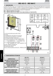
J3<br />
DS1<br />
1 2 3 4 5 6<br />
ø ~ 4 mm<br />
F2<br />
TF1<br />
OPEN<br />
(CARTER)<br />
J4<br />
F1<br />
J9<br />
J1<br />
J2<br />
17 18 19<br />
1 2 3 4 5 6 7 8 9 10 11 12 13 14 15 16<br />
OPEN<br />
STOP<br />
FSW<br />
C<br />
SERVICE LIGHT<br />
MAX 40 W<br />
230Vac<br />
+6% - 10%<br />
1<br />
2<br />
TX<br />
FSW<br />
RX<br />
1<br />
2<br />
3<br />
4<br />
5<br />
24 Vdc<br />
FAIL-SAFE<br />
FCC<br />
FCA<br />
C<br />
BLUE<br />
Fig. 5<br />
Fig. 6<br />
1
ITALIANO<br />
S<br />
Fig. 7<br />
Fig. 8<br />
Fig. 9<br />
ø 25 mm<br />
110 mm<br />
- 5°<br />
Fig. 10<br />
10 cm<br />
A<br />
B<br />
N<br />
Fig. 11<br />
10 cm<br />
A<br />
B<br />
Fig. 12<br />
Fig. 13<br />
T<br />
Fig. 14<br />
L<br />
Fig. 15<br />
2
ITALIANO<br />
DICHIARAZIONE CE DI CONFORMITÁ PER MACCHINE<br />
(DIRETTIVA 89/392 CEE, ALLEGATO II, PARTE B)<br />
Fabbricante:<br />
FAAC S.p.A.<br />
Indirizzo: Via Benini, 1<br />
40069 - Zola Predosa<br />
BOLOGNA-ITALY<br />
Dichiara che: L'operatore mod. <strong>595</strong> I / S,<br />
•è costruito per essere incorporato in una macchina o per essere assemblato<br />
con altri macchinari per costituire una macchina ai sensi della Direttiva 89/<br />
392 CEE, e successive modifiche 91/368/CEE, 93/44/CEE, 93/68/CEE;<br />
•è conforme ai requisiti essenziali di sicurezza delle seguenti altre direttive CEE:<br />
73/23 CEE e successiva modifica 93/68/CEE.<br />
89/336 CEE e successiva modifica 92/31 CEE e 93/68/CEE<br />
e inoltre dichiara che non è consentito mettere in servizio il macchinario fino<br />
a che la macchina in cui sarà incorporata o di cui diverrà componente sia<br />
stata identificata e ne sia stata dichiarata la conformità alle condizioni della<br />
Direttiva 89/392/CEE e successive modifiche trasposta nella legislazione<br />
nazionale dal DPR n° 459 del 24 luglio 1996.<br />
Bologna, 01,gennaio,1997<br />
L’Amministratore<br />
Delegato<br />
A. Bassi<br />
3
ITALIANO<br />
AVVERTENZE PER L’INSTALLATORE<br />
OBBLIGHI GENERALI PER LA SICUREZZA<br />
1) ATTENZIONE! È importante per la sicurezza delle persone seguire attentamente tutte le istruzioni. Una errata<br />
installazione o un errato uso del prodotto può portare a gravi danni alle persone.<br />
2) Leggere attentamente le istruzioni prima di iniziare l’installazione del prodotto.<br />
3) I materiali dell’imballaggio (plastica,polistirolo,ecc.) non devono essere lasciati alla portata dei bambini in quanto<br />
potenziali fonti di pericolo.<br />
4) Conservare le istruzioni per riferimenti futuri.<br />
5) Questo prodotto è stato progettato e costruito esclusivamente per l’utilizzo indicato in questa documentazione.<br />
Qualsiasi altro utilizzo non espressamente indicato potrebbe pregiudicare l’integrità del prodotto e/o rappresentare<br />
fonte di pericolo.<br />
6) FAAC declina qualsiasi responsabilità derivata dall’uso improprio o diverso da quello per cui l’automatismo è<br />
destinato.<br />
7) Non installare l’apparecchio in atmosfera esplosiva: la presenza di gas o fumi infiammabili costituisce un grave<br />
pericolo per la sicurezza.<br />
8) Gli elementi costruttivi meccanici devono essere in accordo con quanto stabilito dalle Normative UNI8612, CEN<br />
pr EN 12604 e CEN pr EN 12605.<br />
Per i Paesi extra-CEE, oltre ai riferimenti normativi nazionali, per ottenere un livello di sicurezza adeguato, devono<br />
essere seguite le Norme sopra riportate.<br />
9) FAAC non è responsabile dell’inosservanza della Buona Tecnica nella costruzione delle chiusure da motorizzare,nonchè<br />
delle deformazioni che dovessero intervenire nell’utilizzo.<br />
10) L’installazione deve essere effettuata nell’osservanza delle Norme UNI8612, CEN pr EN 12453 e CEN pr EN 12635.<br />
Il livello di sicurezza dell’<strong>automazione</strong> deve essere C+E.<br />
11) Prima di effettuare qualsiasi intervento sull’impianto, togliere l’alimentazione elettrica.<br />
12) Prevedere sulla rete di alimentazione dell’<strong>automazione</strong> un interruttore onnipolare con distanza d’apertura dei<br />
contatti uguale o superiore a 3mm. È consigliabile l’uso di un magnetotermico da 6A con interruzione onnipolare.<br />
13) Verificare che a monte dell’impianto vi sia un interruttore differenziale con soglia da 0,03A.<br />
14) Verificare che l’impianto di terra sia realizzato a regola d’arte e collegarvi le parti metalliche della chiusura. Collegare<br />
inoltre a terra il filo Giallo/Verde dell’automatismo.<br />
15) L’<strong>automazione</strong> dispone di una sicurezza intrinseca antischiacciamento costituita da un controllo di coppia che deve<br />
comunque essere sempre accompagnato ad altri dispositivi di sicurezza.<br />
16) I dispositivi di sicurezza (Es.: fotocellule,coste sensibili,ecc...) permettono di proteggere eventuali aree di pericolo da<br />
Rischi meccanici di movimento, come ad Es. schiacciamento, convogliamento, cesoiamento.<br />
17) Per ogni impianto è indispensabile l’utilizzo di almeno una segnalazione luminosa (es: FAAC LAMP, MINILAMP ecc.)<br />
nonchè di un cartello di segnalazione fissato adeguatamente sulla struttura dell’infisso, oltre ai dispositivi citati al punto<br />
“16”.<br />
18) FAAC declina ogni responsabilità ai fini della sicurezza e del buon funzionamento dell’<strong>automazione</strong> in caso vengano<br />
utilizzati componenti dell’impianto non di produzione FAAC.<br />
19) Per la manutenzione utilizzare esclusivamente parti originali FAAC.<br />
20) Non eseguire alcuna modifica sui componenti facenti parte del sistema d’<strong>automazione</strong>.<br />
21) L’installatore deve fornire tutte le informazioni relative al funzionamento manuale del sistema in caso di emergenza<br />
e consegnare all’utilizzatore dell’impianto la "Guida per l'Utente" allegata al prodotto.<br />
22) Non permettere ai bambini o persone di sostare nelle vicinanze del prodotto durante il funzionamento.<br />
23) Tenere fuori dalla portata dei bambini radiocomandi o qualsiasi altro datore di impulso, per evitare che l’<strong>automazione</strong><br />
possa essere azionata involontariamente.<br />
24) L’utilizzatore deve astenersi da qualsiasi tentativo di riparazione o d’intervento diretto e rivolgersi solo a personale<br />
qualificato.<br />
25) Tutto quello che non è previsto espressamente in queste istruzioni non è permesso<br />
4
ITALIANO<br />
AUTOMAZIONE <strong>595</strong> I / S<br />
L’<strong>automazione</strong> <strong>595</strong> I/S è costituita da un monoblocco<br />
oleodinamico composto da una elettropompa e da un<br />
gruppo pistone cremagliera che, applicato al telo dalla<br />
basculante con opportuni accessori, consente di<br />
automatizzare porte basculanti di garages residenziali e<br />
condominiali.<br />
Il sistema è dotato di sicurezza antischiacciamento<br />
regolabile, di un dispositivo che garantisce arresto e blocco<br />
del telo della basculante in qualsiasi posizione e di un<br />
comodo sblocco manuale da manovrare in caso di blackout<br />
o disservizio.<br />
L'<strong>automazione</strong> <strong>595</strong> I/S è stata progettata e costruita per<br />
automatizzare porte basculanti a contrappesi. Nelle figure<br />
1/2/3 sono rappresentate le più comuni tipologie di porte<br />
basculanti. Evitare qualsiasi altro utilizzo.<br />
1. DESCRIZIONE E CARATTERISTICHE TECNICHE<br />
16<br />
3<br />
5<br />
6<br />
7<br />
8<br />
9<br />
10<br />
4<br />
15<br />
2<br />
1<br />
11 12 13<br />
14<br />
Fig. 16<br />
Tab. 1 Caratteristiche tecniche operatore <strong>595</strong> I<br />
Alimentazione<br />
230V~ (+6 -10 %) 50Hz<br />
Potenza assorbita (W) 220<br />
Ciclo di utilizzo % 50<br />
Tipo di olio FAAC XD 220<br />
Quantita’ di olio (l) 1<br />
Termoprotezione<br />
120° C<br />
avvolgimento<br />
Sistema antischiacciamento valvole di bypass di serie<br />
Temperatura ambiente -20 ÷ +55 °C<br />
Grado protezione IP 54<br />
Peso (Kg) 10<br />
Portata della pompa (l/min) 0.75<br />
Velocità angolare (giri/min) 1.54<br />
Peso massimo della porta 15<br />
(Kg/m 2 )<br />
Coppia massima (Nm) 400<br />
Altezza massima della 2.70<br />
porta (m)<br />
con un operatore<br />
Larghezza massima 3.5<br />
della porta (m)<br />
con un operatore<br />
Dati tecnici motore elettrico<br />
Numero di giri/min 1400<br />
Potenza (W) 200<br />
Corrente assorbita (A) 1.2<br />
Alimentazione<br />
230V~ (+6 -10 %) 50Hz<br />
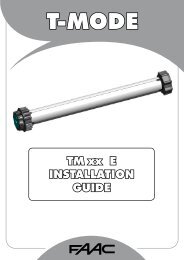
1.1. CURVA DI MASSIMO UTILIZZO<br />
La curva consente di individuare il tempo massimo di<br />
lavoro (T) in funzione della frequenza di utilizzo (F).<br />
Es: Gli operatori <strong>595</strong> I/S possono funzionare<br />
ininterrottamente alla frequenza d’utilizzo del 50%.<br />
Per garantire il buon funzionamento, è necessario operare<br />
nel campo di lavoro sotto la curva.<br />
Importante: La curva è ottenuta alla temperatura di 24 °C.<br />
L’esposizione all’irraggiamento solare diretto può<br />
determinare diminuzioni della frequenza d’utilizzo fino al 20%.<br />
Calcolo della frequenza d’utilizzo<br />
È la percentuale del tempo di lavoro effettivo (apertura +<br />
chiusura) rispetto al tempo totale del ciclo (apertura +<br />
chiusura + tempi di sosta).<br />
La formula di calcolo è la seguente:<br />
serratura di sblocco esterno (opzionale)<br />
supporto laterale fissaggio operatore<br />
flangia superiore<br />
tappo di carico olio<br />
serbatoio olio<br />
pomello di sblocco interno<br />
flangia di distribuzione<br />
valvole di regolazione coppia<br />
corpo centrale per fissaggio operatore<br />
cilindro<br />
flangia inferiore<br />
albero di trasmissione<br />
supporto laterale fissaggio operatore<br />
longherone di fissaggio operatore<br />
vite di sfiato<br />
apparecchiatura 596 MPS<br />
Ta + Tc<br />
%F = X 100<br />
Ta + Tc + Tp + Ti<br />
dove:<br />
Ta = tempo di apertura<br />
Tc = tempo di chiusura<br />
Tp = tempo di pausa<br />
Ti = tempo di intervallo<br />
tra un ciclo<br />
completo e l’altro.<br />
Percentuale<br />
di lav. %<br />
100<br />
90<br />
80<br />
70<br />
60<br />
50<br />
40<br />
30<br />
20<br />
% Duty cycle % Fréquence<br />
d'utilisation<br />
% Benutzungsfrequenz<br />
% Frecuencia<br />
de utilización<br />
10<br />
0 1 2 3 4 5 6 7 8 9 10 11 12<br />
Tempo (h) Time (h) Temps (h) Zeit (Std.) Tiempo (h)<br />
5
ITALIANO<br />
2. PREDISPOSIZIONI ELETTRICHE • “Montaggio ad avvitare”: non occorre eseguire saldature<br />
poichè tutti gli accessori sono predisposti per<br />
essere avvitati.<br />
Per entrambe le versioni sono disponibili bracci telescopici<br />
dritti e bracci telescopici curvi. Nella presente istruzione è<br />
descritta l’installazione con “montaggio ad avvitare“.<br />
4.3. POSIZIONAMENTO DEI BRACCI TELESCOPICI<br />
Lo spazio tra braccio di bilanciamento esistente e infisso<br />
(S) fig. 7 deve essere di almeno 15 mm, per consentire la<br />
rotazione dei bracci telescopici affiancati, come indicato<br />
nella fig. 11.<br />
Qualora lo spazio (S) risultasse inferiore ai 15 mm occorre<br />
utilizzare bracci telescopici curvi realizzando l’installazione<br />
come indicato in fig. 13. Riferendosi alla fig. 4 fissare gli<br />
squadretti (D) sull’infisso nel punto più vicino possibile al<br />
cassetta di derivazione<br />
supporto superiore del braccio di bilanciamento esistente.<br />
pulsantiera T15MP<br />
Montare le guaine dei bracci telescopici.<br />
operatore FAAC <strong>595</strong> I<br />
Rispettando le dimensioni massime della porta riportate<br />
fotocellula Rx<br />
nelle caratteristiche tecniche, applicare un solo operatore<br />
radioricevente plus<br />
(FAAC <strong>595</strong>) al centro del telo, fig. 8, o due operatori ai lati<br />
pulsante a chiave T10<br />
della porta (<strong>595</strong> I e <strong>595</strong> S), fig. 9.<br />
<br />
fotocellula Tx<br />
3. DIMENSIONI<br />
4. INSTALLAZIONE<br />
4.1. VERIFICHE PRELIMINARI<br />
Fig. 17<br />
Fig. 18<br />
Verificare che le dimensioni del portone siano conformi a<br />
quelle indicate nelle caratteristiche tecniche.<br />
Verificare che il portone sia privo di attriti. Eventualmente<br />
pulire ed oliare le guide, con lubrificante al silicone,evitando<br />
l'impiego di grasso. Controllare l’efficenza dei cuscinetti e<br />
dei giunti del portone. Rimuovere le chiusure meccaniche<br />
del portone, affinchè sia l’automatismo a bloccarlo in<br />
chiusura. Verificare che vi sia una fonte di alimentazione<br />
autonoma protetta da regolare interruttore differenziale<br />
adeguato a 230 Vac, all’interno dell’autorimessa.<br />
L’operatore FAAC <strong>595</strong> I automatizza porte basculanti a<br />
contrappesi di diverse tipologie. Nelle fig. 1/2/3 sono<br />
rappresentate le più diffuse: a telo unico debordante, a<br />
telo snodato debordante, a telo unico non debordante<br />
con guide orizzontali. I contrappesi per il corretto<br />
bilanciamento del telo sono normalmente costituiti da<br />
lingotti metallici o in muratura. Alcuni produttori di basculanti<br />
utilizzano molle di bilanciamento al posto dei contrappesi.<br />
Assicurarsi pertanto che la porta basculante compia un<br />
movimento di rotazione su se stessa nelle fasi di apertura e<br />
chiusura.<br />
4.2. INSTALLAZIONE OPERATORE<br />
Gli accessori degli operatori FAAC <strong>595</strong> I/S sono realizzati<br />
in due versioni:<br />
• “Montaggio a saldare”: occorre eseguire saldature sui<br />
bracci telescopici, tubi di trasmissione, staffe di fissaggio.<br />
6<br />
4.4. POSIZIONAMENTO LONGHERONE / OPERATORE / TUBI<br />
DI TRASMISSIONE<br />
Il longherone (Z) è dotato di forature (M) e (N) che ne<br />
permettono il posizionamento sulla traversa superiore della<br />
porta come indicato nei riquadri A e B di fig. 4.<br />
Con porte che non superano i 2100 mm di altezza, montare<br />
il longherone con (M) sulla traversa superiore (vedi riquadro<br />
A). Con porte che superano i 2100 mm, montarlo con (N)<br />
sulla traversa superiore (vedi riquadro B) fig. 4. Eseguire<br />
due forature (U) di diametro 6 mm per il fissaggio del<br />
longherone nel rinforzo intermedio della basculante fig. 4.<br />
Se la struttura della basculante non è sufficentemente<br />
robusta, (lamiera sottile) è consigliabile l’utilizzo di inserti<br />
filettati. In alternativa è possibile utilizzare le viti autofilettanti<br />
in dotazione.<br />
Definire il punto di rotazione dell’albero di trasmissione<br />
dell’operatore a 10 cm dal fulcro inferiore del braccio<br />
esistente fig. 11/13.<br />
Togliere la vite di sfiato (F) e fissare l’operatore per mezzo<br />
delle staffe (S) sul longherone come indicato in fig. 4.<br />
Sbloccare l’operatore portando la basculante in apertura<br />
come indicato in fig. 10 e ruotare il pignone nel senso della<br />
freccia fino a battuta del pistone. Ruotare di circa 5° in<br />
senso contrario.<br />
Riportare la porta in chiusura e introdurre i tubi di trasmissione<br />
(T) fig. 4 sui pignoni dell’operatore. Tagliarli a misura come<br />
indicato nelle fig. 8/9. Introdurre successivamente le<br />
boccole (C) e le staffe (L) fig. 4 nei tubi di trasmissione ed<br />
avvitare le staffe (L) sui rinforzi della basculante avendo<br />
cura di mantenere un corretto allineamento dei tubi di<br />
trasmissione.<br />
Braccio dritto: riferirsi alla fig. 11. Braccio curvo: riferirsi alla fig. 13.<br />
Portare la basculante in apertura e simulare il<br />
posizionamento del braccio telescopico come indicato<br />
nelle fig. 11 o 13. Tagliare la guaina nel punto di rif. A.<br />
Tagliare il braccio maschio nel punto di rif. B.<br />
Lasciare un gioco di circa 1 cm in prossimità dei punti di<br />
battuta.<br />
Introdurre il tubo quadro di trasmissione (T) nel braccio<br />
maschio (Q) fig.4 tagliato a misura ed effettuare una<br />
foratura di diam. 8 mm. Avvitare la vite di 8 MA.<br />
Per favorire il moto di chiusura della basculante installare il<br />
tampone T fig.14. In alternativa per evitare che il peso<br />
dell’<strong>automazione</strong> crei uno sbilanciamento della porta<br />
all’interno dell’autorimessa ed avere un funzionamento<br />
ottimale dell’operatore, costruire ed installare una staffa<br />
ad L come in fig.15.
ITALIANO<br />
4.5. REGOLAZIONE DEI CONTRAPPESI<br />
Per un movimento regolare della basculante occorre<br />
aggiungere materiale nei contrappesi. Qualora non ci sia<br />
lo spazio sufficente sostituirli con lingotti di peso specifico<br />
maggiore. Sbloccare l’operatore e verificare che in<br />
posizione intermedia (45°) la basculante rimanga in<br />
equilibrio.<br />
4.6. APPLICAZIONE DOPPIA<br />
Per porte basculanti con larghezza da 3,50 a 5 m, è<br />
necessario utilizzare un operatore <strong>595</strong> I (integrato) e un<br />
operatore <strong>595</strong> S (slave). L'altezza massima ammessa è di<br />
3 m. Il criterio di installazione (fig. 9) è lo stesso che viene<br />
utilizzato per l'applicazione di un motore singolo. Ultimata<br />
la posa meccanica eseguire i cablaggi elettrici riportati in<br />
fig. 20.<br />
LAYOUT E COLLEGAMENTI ELETTRICI<br />
J3<br />
DS1<br />
J4<br />
J1<br />
F2<br />
1 2 3 4 5 6<br />
<br />
<br />
<br />
<br />
J2<br />
<br />
TF1<br />
<br />
<br />
J9<br />
F1<br />
17 18 19<br />
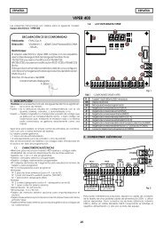
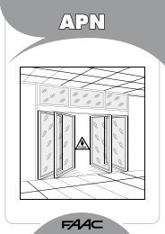
5. APPARECCHIATURA ELETTRONICA 596 MPS<br />
5.1. COLLEGAMENTO APPARECCHIATURA ELETTRONICA<br />
Attenzione: Prima di effettuare qualsiasi tipo di intervento<br />
sull'apparecchiatura elettronica (collegamenti,<br />
programmazione, manutenzione), togliere sempre<br />
l'alimentazione elettrica.<br />
Seguire i punti 10.11.12.13.14 degli OBBLIGHI GENERALI PER<br />
LA SICUREZZA.<br />
Tab.2: Caratteristiche tecniche app. elettr. 596 MPS<br />
Tensione d’alimentazione<br />
Potenza assorbita<br />
Carico max motore<br />
Carico max accessori<br />
230 V~ ( +6% -10%) - 50 Hz<br />
10 W<br />
800 W<br />
0,250 A<br />
Temperatura ambiente -20 °C +55 °C<br />
Fusibili di protezione N° 2 (vedi fig. 19)<br />
Logiche di funzionamento<br />
Automatica / Semiautomatica<br />
Tempo d’apertura/chiusura Selezionabile tramite dip-switch (da 25 a 40 s)<br />
Tempo di pausa Selezionabile tramite dip-switch (30 o 60 s)<br />
Ingressi in morsettiera Open/Stop/ Sicurezze in ch./Alimentazione+Terra<br />
Uscite in morsettiera<br />
Motore - Alimentazione accessori 24 Vdc<br />
Condensatore di spunto -Lampada di cortesia 230 Vac<br />
Connettore rapido<br />
Schede di decodifica - Ricevitore RP SL/DS<br />
Funzioni selezionabili a microinterrutore Logiche di funzionamento -<br />
Fail-safe - Tempi A/C -Tempo pausa -<br />
Logica d’intervento delle sicurezze in chiusura<br />
1 2 3 4 5 6 7 8 9 10 11 12 13 14 15 16<br />
Fig. 19<br />
Seguendo le indicazioni di Fig. 17 predisporre le<br />
canalizzazioni ed effettuare i collegamenti elettrici<br />
dell'apparecchiatura elettronica 596 con gli accessori<br />
prescelti.<br />
Morsettiera J1 (fig. 19) a bassa tensione è utilizzata per<br />
collegare tutti gli accessori (vedi tab. 3).<br />
1 - Comando di OPEN (N.A.): si intende qualsiasi dispositivo<br />
(pulsante, fotocellula, detector, etc.) che,<br />
chiudendo un contatto, può dare un impulso<br />
d’apertura e/o chiusura alla porta.<br />
Per installare più datori d’impulso d’apertura collegare<br />
i contatti N.A. in parallelo.<br />
2 - Sicurezze<br />
Si intendono tutti i dispositivi (fotocellule, coste<br />
sensibili, spire magnetiche) con contatto N.C. (normalmente<br />
chiuso), che in presenza di un ostacolo<br />
nell'area protetta dalle sicurezze intervengono,<br />
interrompendo il movimento della porta.<br />
Per installare più datori dispositivi di sicurezza collegare<br />
i contatti N.C. in serie.<br />
Nota bene: Se non vengono collegati dispositivi di<br />
sicurezza, ponticellare i morsetti 2 e 4.<br />
J1<br />
J2<br />
J9<br />
17 18 19<br />
1 2 3 4 5 6 7 8 9 10 11 12 13 14 15 16<br />
OPEN<br />
STOP<br />
FSW<br />
C<br />
SERVICE LIGHT<br />
MAX 40 W<br />
230Vac<br />
+6% - 10%<br />
1<br />
2<br />
TX<br />
FSW<br />
RX<br />
1<br />
2<br />
3<br />
4<br />
5<br />
24 Vdc<br />
FAIL-SAFE<br />
FCC<br />
FCA<br />
C<br />
BLUE<br />
Fig. 20<br />
7
ITALIANO<br />
3 - N.C. - Contatto di STOP: si intende qualsiasi dispositivo<br />
(es.: pulsante) che aprendo un contatto N.C.<br />
può arrestare il moto della porta.<br />
Per installare più dispositivi d’arresto collegare i<br />
contatti N.C. in serie.<br />
Nota bene: Se non vengono collegati dispositivi di<br />
STOP, ponticellare i morsetti 3 e 4.<br />
4 - Comune segnali e negativo alimentazione accessori<br />
5 - + Positivo alimentazione accessori ( + 24 Vdc )<br />
Attenzione: Il carico max degli accessori è di 250 mA.<br />
Per calcolare gli assorbimenti fare riferimento alla tab.<br />
3.<br />
6 - Fail-safe: se abilitato, collegare obbligatoriamente<br />
il positivo delle alimentazioni dei trasmettitori<br />
delle fotocellule.<br />
7 - Contatto finecorsa di chiusura N.A. (normalmente<br />
aperto).<br />
8 - Comune contatti finecorsa.<br />
9 - Contatto finecorsa di apertura N.A. (normalmente<br />
aperto).<br />
Nota bene: Se non vengono collegati dispositivi di<br />
finecorsa, non eseguire ponticelli.<br />
Tab. 3 - Consumo accessori<br />
TIPO ACCESSORIO<br />
R 31<br />
RICEVENTE PLUS E<br />
MINIDEC SL / DS<br />
DECODER SL / DS<br />
RICEVENTE RP SL / DS<br />
DIGICARD<br />
METAL DIGIKEY<br />
FOTOSWITCH<br />
DETECTOR F4 / PS6<br />
MINIBEAM<br />
CORRENTE NOMINALE ASSORBITA<br />
50 mA<br />
20 mA<br />
6 mA<br />
20 mA / 55 mA<br />
12 mA / 6 mA<br />
15 mA<br />
15 mA<br />
90 mA<br />
50 mA<br />
70 mA<br />
5.2.2. COMPORTAMENTO SICUREZZE IN CHIUSURA<br />
Questa funzione permette di scegliere l'effetto sul<br />
funzionamento del sistema all'intervento delle sicurezze in<br />
chiusura:<br />
- OFF:inversione immediata del moto di chiusura della<br />
porta basculante;<br />
- ON: arresto del moto di chiusura della porta basculante<br />
ed inversione in apertura al disimpegno della sicurezza.<br />
Morsettiera J2 (fig. 19)<br />
10 - 11 - Collegamento condensatore di spunto.<br />
12 - 13 - 14 - Collegamento motore elettrico.<br />
Nota bene: nel caso di applicazione di doppio<br />
motore collegare il secondo motore in parallelo a<br />
quello già cablato.<br />
15 - 16 - Luce di cortesia temporizzata (230 Vac max<br />
40W).<br />
596 MPS<br />
PLUS E<br />
596 MPS<br />
PLUS E<br />
Morsettiera J9 (fig. 19)<br />
: Collegamento di terra<br />
N. : Alimentazione 230 V~ ( Neutro )<br />
L. : Alimentazione 230 V~ ( Linea )<br />
Nota bene: Per un corretto funzionamento è obbligatorio<br />
il collegamento della scheda al conduttore<br />
di terra presente nell'impianto. Prevedere a<br />
monte del sistema un adeguato interruttore<br />
magnetotermico differenziale.<br />
Microinterruttori di programmazione<br />
Fusibile F1 5x20 5 A/250 V rapido (alimentazione motori)<br />
Fusibile F2 5x20 800 mA/250 V ritardato (alimentazione<br />
accessori)<br />
Connettore J4 per collegamento rapido di schede<br />
DECODER SL / DS - MINIDEC SL / DS - RP SL / DS (figg. 21-<br />
22-23-24).<br />
5.2. PROGRAMMAZIONE DEI MICROINTERRUTTORI<br />
Per programmare il funzionamento dell’<strong>automazione</strong> è<br />
necessario agire sugli appositi microinterruttori come da<br />
schema riportato in Tab. 4.<br />
5.2.1. LOGICHE DI FUNZIONAMENTO<br />
Le due logiche disponibili sono le seguenti:<br />
A : “AUTOMATICA” E : “SEMIAUTOMATICA”<br />
Il funzionamento delle diverse logiche è indicato nelle<br />
tabelle 5/a e 5/b.<br />
PLUS E<br />
596 MPS<br />
MINIDEC<br />
SL/DS<br />
DECODER<br />
SL<br />
Fig. 21 Fig. 22<br />
N.B.: Accessori di tipo diverso tra loro necessitano di un<br />
decoder dedicato<br />
Fig. 23<br />
RP DS<br />
RP SL<br />
596 MPS<br />
Fig. 24<br />
8
ITALIANO<br />
LOGICA<br />
A<br />
E<br />
FSW<br />
apre al disimpegno<br />
apre immediatamente<br />
SW1<br />
ON<br />
OFF<br />
SW2<br />
ON<br />
OFF<br />
ON<br />
OFF<br />
1 2 3 4 5 6<br />
TEMPI A/C<br />
25"<br />
30"<br />
35"<br />
SW3<br />
ON<br />
OFF<br />
ON<br />
OFF<br />
SW4<br />
ON<br />
ON<br />
OFF<br />
OFF<br />
FAIL SAFE<br />
SI<br />
NO<br />
TEMPO PAUSA<br />
60"<br />
30"<br />
SW6<br />
ON<br />
OFF<br />
SW5<br />
ON<br />
OFF<br />
40" Tab. 4<br />
Tab. 5/a<br />
LOGICA "A"<br />
STATO PORTA OPEN<br />
IMPULSI<br />
STOP<br />
CHIUSA<br />
Apre la porta e richiude dopo il tempo di pausa<br />
Nessun effetto (OPEN inibito)<br />
SICUREZZE<br />
Nessun effetto<br />
APERTA in PAUSA<br />
Richiude la porta immediatamente<br />
Congela la pausa fino al disimpegno (OPEN inibito)<br />
IN CHIUSURA<br />
Riapre la porta immediatamente<br />
Blocca il<br />
funzionamento<br />
vedi paragrafo 5.2.2<br />
IN APERTURA<br />
Nessun effetto<br />
Nessun effetto<br />
BLOCCATA<br />
Chiude la porta<br />
Nessun effetto (OPEN inibito)<br />
Nessun effetto (OPEN inibito)<br />
Tab. 5/b<br />
LOGICA "E"<br />
STATO PORTA OPEN<br />
IMPULSI<br />
STOP<br />
CHIUSA<br />
Apre la porta e richiude dopo il tempo di pausa<br />
Nessun effetto (OPEN inibito)<br />
SICUREZZE<br />
Nessun effetto<br />
APERTA in PAUSA<br />
Richiude la porta immediatamente<br />
Congela la pausa fino al disimpegno (OPEN inibito)<br />
IN CHIUSURA<br />
Riapre la porta immediatamente<br />
Blocca il<br />
funzionamento<br />
vedi paragrafo 5.2.2<br />
IN APERTURA<br />
Richiude la porta immediatamente<br />
Nessun effetto<br />
BLOCCATA<br />
Chiude la porta<br />
Nessun effetto (OPEN inibito)<br />
Nessun effetto (OPEN inibito)<br />
6. MESSA IN FUNZIONE<br />
Programmare l’apparecchiatura elettronica 596 MPS<br />
secondo le proprie esigenze come da tabella 4.<br />
6.1. VERIFICA DEL SENSO DI ROTAZIONE<br />
1) Togliere l’alimentazione all’apparecchiatura elettronica<br />
di comando.<br />
2) Portare manualmente la porta sulla mezzeria dell’angolo<br />
d’apertura.<br />
3) Ribloccare l'operatore.<br />
4) Ripristinare la tensione d’alimentazione.<br />
5) Inviare un impulso di OPEN sull’ingresso (fig. 20) e verificare<br />
che si comandi un’apertura della porta.<br />
Nel caso il primo impulso di OPEN comandi una chiusura,<br />
è necessario invertire sulla morsettiera dell’app. elettr. le<br />
fasi del motore elettrico (cavi marron e nero).<br />
6.2. SELEZIONE DEL TEMPO DI FUNZIONAMENTO<br />
Selezionare sull'apparecchiatura elettronica 596 MPS un<br />
tempo di lavoro superiore di qualche secondo a quello<br />
cronometrato in precedenza, al fine di ottenere la massima<br />
efficienza del blocco idraulico.<br />
6.3. SELEZIONE DEL TEMPO DI PAUSA<br />
Selezionando la logica A è possibile regolare il tempo di<br />
arresto momentaneo della porta basculante attraverso<br />
l'apposito dip-switch.<br />
6.4. SELEZIONE DEL FAIL-SAFE<br />
La scheda 596 MPS è dotata di un ulteriore dispositivo di<br />
sicurezza FAIL-SAFE, il cui compito è quello di verificare,<br />
prima di ogni azionamento, l'effettivo funzionamento del<br />
contatto N.C. posto nel ricevitore della fotocellula; questo<br />
dispositivo è comunque escludibile.<br />
9
ITALIANO<br />
6.5. REGOLAZIONE DELLA COPPIA TRASMESSA<br />
L’<strong>automazione</strong> <strong>595</strong> I/S è dotata di un sistema<br />
antischiacciamento che garantisce l’arresto del<br />
movimento in presenza di un ostacolo.<br />
Avviare la basculante in apertura e regolare tramite la vite<br />
verde (V) fig. 4 la coppia dell’operatore. Ripetere<br />
l’operazione in chiusura agendo sulla vite rossa (R) fig. 4.<br />
Una corretta regolazione si ottiene quando la basculante<br />
si arresta con una forza di 15 Kg applicati sul bordo<br />
inferiore del telo.<br />
Per aumentare la coppia ruotare le viti in senso orario, per<br />
diminuire la coppia ruotare le viti in senso antiorario.<br />
Eseguite le operazioni di regolazione, applicare<br />
sull'operatore mediante le apposite viti il carter di<br />
protezione.<br />
6.6. PROVA DELL'AUTOMAZIONE<br />
Terminata l'installazione, applicare gli adesivi di<br />
segnalazione pericolo tra i tubi di trasmissione e i bracci<br />
telescopici (figg. 8-9). Procedere alla verifica funzionale<br />
accurata dell'<strong>automazione</strong> e di tutti gli accessori ad essa<br />
collegati.<br />
Consegnare al cliente la "Guida per l'utente", illustrare il<br />
corretto funzionamento e utilizzo dell'operatore ed<br />
evidenziare le zone di potenziale pericolo<br />
dell'<strong>automazione</strong>.<br />
7. FUNZIONAMENTO MANUALE<br />
Nel caso sia necessario azionare manualmente la<br />
basculante in caso di mancanza di alimentazione o<br />
disservizio dell’<strong>automazione</strong>, è necessario agire sul<br />
dispositivo di sblocco a pomello fig. 25.<br />
È possibile applicare uno sblocco d’emergenza a chiave<br />
personalizzata azionabile dall’esterno fig. 26 (opzionale).<br />
8. RIPRISTINO DEL FUNZIONAMENTO NORMALE<br />
Per evitare che un impulso involontario possa azionare la<br />
basculante durante la manovra, prima di ripristinare il<br />
funzionamento normale, togliere l’alimentazione<br />
all’impianto.<br />
pomello (standard):<br />
- ruotare il pomello in senso orario fino all’arresto.<br />
chiave personalizzata (opzionale):<br />
- ruotare la chiave in senso orario fino all’arresto.<br />
- ruotare lentamente ed in senso antiorario la chiave fino<br />
al punto in cui è possibile estrarla.<br />
9. ACCESSORI DISPONIBILI<br />
Kit finecorsa<br />
Il kit finecorsa permette di arrestare il telo della basculante<br />
in due posizioni ben definite.<br />
L'abbinamento del kit finecorsa sull'operatore FAAC <strong>595</strong> I<br />
è vincolato all'utilizzo di una scheda elettronica,<br />
predisposta per tale funzione. Stabilita questa condizione<br />
procedere come segue:<br />
1. Estrarre i tubi dagli appositi pignoni e montare le<br />
camme di riferimento.<br />
2. Togliere le viti di fissaggio dell'operatore sui longheroni,<br />
aggiungere le rondelle piane in dotazione e montare<br />
i supporti dei finecorsa.<br />
3. Serrare le viti e montare i finecorsa nelle apposite sedi<br />
di fissaggio.<br />
4. Aprire la basculante fino al punto desiderato e ruotare<br />
la camma A del microinterruttore FCA fino all'attivazione<br />
del micro.<br />
5. Portare la basculante in chiusura e ruotare la camma<br />
B del microinterruttore FCC fino all'attivazione del micro.<br />
6. Serrare le viti autofilettanti poste sulle camme.<br />
SBLOCCA/UNLOCK<br />
DEBLOQUE/ENTRIEGELT<br />
DESBLOQUEAR<br />
BLOCCA/LOCK<br />
BLOQUE/VERRIEGELT<br />
BLOQUEAR<br />
Fig. 25<br />
SBLOCCA/UNLOCK<br />
DEBLOQUE/ENTRIEGELT<br />
DESBLOQUEAR<br />
FCC<br />
FCA<br />
BLOCCA/LOCK<br />
BLOQUE/VERRIEGELT<br />
BLOQUEAR<br />
B<br />
A<br />
Fig. 27<br />
Fig. 26<br />
- Inserire la chiave nella serratura e ruotarla in senso<br />
antiorario di 1 giro.<br />
- Effettuare manualmente la manovra di apertura o chiusura<br />
della porta.<br />
Sblocco esterno a chiave personalizzata Figg. 12-28<br />
Lo sblocco a chiave personalizzata permette di attivare la<br />
basculante in caso di avaria o disservizio dall'esterno<br />
dell'autorimessa.<br />
10
ITALIANO<br />
Per frequenze di utilizzo medio-basse è sufficiente un<br />
controllo annuale; per utilizzi più gravosi è consigliabile<br />
ogni 6 mesi.<br />
Il livello non deve scendere sotto l’indice<br />
Per effettuare il rabbocco, svitare il tappo di carico (Fig.<br />
16) e versare l’olio fino al livello.<br />
Utilizzare esclusivamente olio FAAC XD 220.<br />
10. MANUTENZIONE<br />
Fig. 28<br />
In occasione delle manutenzioni verificare sempre le<br />
corrette tarature delle viti di by-pass, il corretto<br />
bilanciamento del telo della basculante e il corretto<br />
funzionamento dei dispositivi di sicurezza.<br />
10.1. RABBOCCO DELL’OLIO<br />
Verificare periodicamente la quantita dell’olio all’interno<br />
del serbatoio.<br />
10.2. OPERAZIONE DI SPURGO<br />
Nel caso che il movimento della porta sia irregolare, ciò<br />
può essere causato dalla presenza di aria nel circuito<br />
oleodinamico.<br />
Qualora si rendesse necessario eseguire una manovra di<br />
spurgo dell’aria, operare come segue:<br />
1) Accertarsi che la vite di sfiato sia stata eliminata<br />
(Fig. 16)<br />
2) Disassemblare i tubi di trasmissione laterali dall'operatore.<br />
3) Impostare sull'apparecchiatura elettronica di comando<br />
un tempo di funzionamento di circa 1 minuto.<br />
4) Azionare elettricamente l’operatore fino a portarlo a<br />
fine corsa alternativamente nei due sensi di rotazione.<br />
5) Se necessario ripetere diverse volte l’operazione.<br />
6) Procedere al rimontaggio seguendo le istruzioni di<br />
installazione.<br />
11. RIPARAZIONI<br />
Per eventuali riparazioni, rivolgersi ai Centri di Riparazione<br />
FAAC autorizzati.<br />
11
ITALIANO<br />
Guida per l'utente<br />
AUTOMAZIONE <strong>595</strong> I / S<br />
NORME GENERALI DI SICUREZZA<br />
L’<strong>automazione</strong> <strong>595</strong> I/S, se correttamente installata ed<br />
utilizzata, garantisce un elevato grado di sicurezza.<br />
Alcune semplici norme di comportamento possono evitare<br />
inoltre inconvenienti accidentali:<br />
- Non transitare sotto il telo della basculante quando questa<br />
è in movimento. Prima di transitare sotto la porta,<br />
attendere l’apertura completa.<br />
- Non sostare assolutamente sotto la porta.<br />
- Non sostare e non permettere a bambini,persone o cose<br />
di sostare nelle vicinanze dell’<strong>automazione</strong>, evitandolo<br />
ancor più durante il funzionamento.<br />
- Tenere fuori dalla portata dei bambini, radiocomandi o<br />
qualsiasi altro datore d’impulso per evitare che l’<strong>automazione</strong><br />
possa essere azionata involontariamente<br />
- Non permettere ai bambini di giocare con l’<strong>automazione</strong>.<br />
- Non contrastare volontariamente il movimento della porta<br />
basculante.<br />
- Non tentare di azionare manualmente la porta basculante<br />
se non dopo averla sbloccata.<br />
- In caso di malfunzionamenti, sbloccare la porta basculante<br />
per consentire l’accesso ed attendere l’intervento tecnico<br />
di personale qualificato.<br />
- Una volta predisposto il funzionamento manuale, prima di<br />
ripristinare il funzionamento normale, togliere alimentazione<br />
elettrica all’impianto.<br />
- Non eseguire alcuna modifica sui componenti facenti<br />
parte il sistema d’<strong>automazione</strong>.<br />
- Astenersi da qualsiasi tentativo di riparazione o d’intervento<br />
diretto e rivolgersi solo a personale qualificato.<br />
- Far verificare almeno semestralmente l’efficienza<br />
dell’<strong>automazione</strong>,dei dispositivi di sicurezza e del collegamento<br />
di terra da personale qualificato.<br />
DESCRIZIONE<br />
L’<strong>automazione</strong> <strong>595</strong> I/S è un operatore per porte basculanti<br />
contrappesate ideale per il controllo di aree di accesso<br />
veicolare fino a 5 m di larghezza (applicazione doppio<br />
operatore) e a media frequenza di transito.<br />
Il funzionamento è gestito da una centralina elettronica di<br />
comando racchiusa in un contenitore con adeguato grado<br />
di protezione agli agenti atmosferici, e che può essere<br />
alloggiato all’interno del garage.<br />
La porta normalmente si trova chiusa in posizione verticale.<br />
Quando la centralina elettronica riceve un comando di<br />
apertura tramite il radiocomando o qualsiasi altro datore di<br />
impulso, aziona l’apparato oleodinamico ottenendo la<br />
rotazione della porta di 90° fino alla posizione orizzontale<br />
che consente l’accesso. Se è stato impostato il<br />
funzionamento automatico, la porta si richiude da sola<br />
dopo il tempo di pausa selezionato.<br />
Se è stato impostato il funzionamento semiautomatico, è<br />
necessario inviare un secondo impulso per ottenere la<br />
richiusura.<br />
Un impulso di apertura dato durante la fase di richiusura,<br />
provoca sempre l’inversione del movimento.<br />
Un impulso di stop (se previsto) arresta sempre il movimento.<br />
Per il dettagliato comportamento della basculante nelle<br />
diverse logiche di funzionamento, fare riferimento al<br />
Tecnico installatore.<br />
Nelle automazioni possono essere presenti dispositivi di<br />
sicurezza (fotocellule) che impediscono la richiusura della<br />
porta quando un ostacolo si trova nella zona da loro<br />
protetta.<br />
L’<strong>automazione</strong> <strong>595</strong> I/S dispone di serie di un dispositivo di<br />
sicurezza antischiacciamento che limita la coppia<br />
trasmessa alla porta basculante.<br />
Il sistema oleodinamico garantisce il blocco della porta in<br />
qualsiasi posizione.<br />
L’apertura manuale è quindi possibile solo intervenendo<br />
sull’apposito sistema di sblocco.<br />
FUNZIONAMENTO MANUALE<br />
Nel caso sia necessario azionare manualmente la porta a<br />
causa di mancanza di alimentazione elettrica o disservizio<br />
dell’<strong>automazione</strong>, è necessario agire sul dispositivo di<br />
sblocco come segue.<br />
Sblocco a leva v. Fig. 1.<br />
SBLOCCA/UNLOCK<br />
DEBLOQUE/ENTRIEGELT<br />
DESBLOQUEAR<br />
BLOCCA/LOCK<br />
BLOQUE/VERRIEGELT<br />
BLOQUEAR<br />
SBLOCCA/UNLOCK<br />
DEBLOQUE/ENTRIEGELT<br />
DESBLOQUEAR<br />
BLOCCA/LOCK<br />
BLOQUE/VERRIEGELT<br />
BLOQUEAR<br />
Fig. 1<br />
Fig. 2<br />
Sblocco a chiave dall'esterno (Fig. 2):<br />
- Inserire la chiave nella serratura e ruotarla in senso antiorario<br />
di 1 giro.<br />
- Effettuare manualmente la manovra di apertura o chiusura<br />
della porta.<br />
RIPRISTINO DEL FUNZIONAMENTO NORMALE<br />
Per evitare che un impulso involontario possa azionare la<br />
porta durante la manovra, prima di ripristinare il funzionamento<br />
normale togliere alimentazione all’impianto.<br />
Sblocco a leva v. Fig. 1.<br />
Sblocco a chiave dall'esterno (Fig. 2):<br />
- ruotare la chiave in senso orario fino all’arresto.<br />
- ruotare molto lentamente ed in senso antiorario la chiave<br />
fino al punto in cui è possibile estrarla.<br />
12
ENGLISH<br />
EC MACHINE DIRECTIVE COMPLIANCE DECLARATION<br />
(DIRECTIVE 89/392 EEC, APPENDIX II, PART B)<br />
Manufacturer: FAAC S.p.A.<br />
Address: Via Benini, 1<br />
40069 - Zola Predosa<br />
BOLOGNA - ITALY<br />
Hereby declares that: the <strong>595</strong> I / S automation system<br />
•is intended to be incorporated into machinery, or to be assembled with other<br />
machinery to constitute machinery in compliance with the requirements of<br />
Directive 89/392 EEC, and subsequent amendments 91/368 EEC, 93/44 EEC<br />
and 93/68 EEC;<br />
•complies with the essential safety requirements in the following EEC Directives:<br />
73/23 EEC and subsequent amendment 93/68 EEC.<br />
89/336 EEC and subsequent amendments 92/31 EEC and 93/68 EEC.<br />
and furthermore declares that unit must not be put into service until the<br />
machinery into which it is incorporated or of which it is a component has<br />
been identified and declared to be in conformity with the provisions of<br />
Directive 89/392 EEC and subsequent amendments enacted by the national<br />
implementing legislation.<br />
Bologna, 1 January 1997<br />
Managing<br />
Director<br />
A. Bassi<br />
12
ENGLISH<br />
IMPORTANT NOTICE FOR THE INSTALLER<br />
GENERAL SAFETY REGULATIONS<br />
1) WARNING! FAAC strongly recommends to follow these instructions literally for the safety of persons. Improper<br />
installation or misuse of the product will cause very serious damages to persons.<br />
2) Packaging material (plastic, polystyrene etc.) is a potential hazard and must be kept out of reach of children.<br />
3) Read the instructions carefully before installing the product.<br />
4) Keep these instructions for future reference.<br />
5) This product has been designed and manufactured only for the use stated in this manual. Any other use not expressly<br />
set forth will affect the reliability of the product and/or could be source of hazard.<br />
6) FAAC S.p.A. cannot be held responsible for any damage caused by improper use or different from the use for which<br />
the automation system is destined to.<br />
7) Do not use this device in areas subject to explosion: the presence of flammable gas or fumes is a serious hazard.<br />
8) Mechanical constructive elements must comply with UNI8612, CEN pr EN 12604 and CEN pr EN 12605 standards.<br />
Countries outside the EC shall follow the regulations above besides their national normative references in order to<br />
offer the utmost safety.<br />
9) FAAC cannot be held responsible for failure to observe technical standards in the construction of gates and doors,<br />
or for any deformation of the gates which may occur during use.<br />
10) Installation must comply with UNI8612, CEN pr EN 12453 and CEN pr EN 12635.<br />
The degree of safety of the automation must be C+E.<br />
11) Before carrying out any operations, turn off the system’s main switch.<br />
12) An omnipower switch shall be provided for the installation with an opening distance of the contacts of 3 mm or more.<br />
Alternatively, use a 6A thermomagnetic breaker with multi-pole switching.<br />
13) Ensure that there is a differential switch up-line of the electrical system, with a trip threshold of 0.03A.<br />
14) Check that the earthing plant is in perfect condition and connect it to the metallic parts. Also earth the yellow/green<br />
wire of the operator.<br />
15) The automation is fitted with an anti-crush safety system that is a torque control device. In any case, further safety<br />
devices shall be installed.<br />
16) The safety devices (e.g. photocells, safety edges, etc.) protect areas where there is a mechanical movement hazard,<br />
e.g. crushing, entrapment and cutting.<br />
17) Each installation must be fitted with at least one flashing light (e.g. FAAC LAMP, MINILAMP etc.) as well as a warning<br />
plate suitably fixed to the gate, besides the safety devices as per point 16. above.<br />
18) FAAC cannot be held responsible regarding safety and correct functioning of the automation in the event that parts<br />
other than FAAC original parts are used.<br />
19) Use only FAAC original spare parts for maintenance operations.<br />
20) Do not carry out any modifications to automation components.<br />
21) The installer must supply all information regarding manual operation of the system in the event of an emergency and<br />
provide the end-user with the "End-user Guide" attached to the product.<br />
22) Keep out of persons when the product is in operation.<br />
23) Keep out of reach of children the remote radio controls and any control devices. The automation could be operated<br />
unintentionally.<br />
24) The end-user must avoid any attempt to repair or adjust the automation personally. These operations must be carried<br />
out exclusively by qualified personnel.<br />
25) What is not explicitly stated in these instructions is not permitted.<br />
13
ENGLISH<br />
THE <strong>595</strong> I/S AUTOMATION SYSTEM<br />
The <strong>595</strong> I/S automation system is a hydraulic unit formed of<br />
a motor pump and a piston-rack assembly, which ensures<br />
optimal automation of up-and-over garage doors. It is<br />
mounted on the door by means of accessories.<br />
The system has an adjustable anti-crushing safety system, a<br />
device that stops and locks the door in any position, and a<br />
convenient manual release device to be used in the event<br />
of a power failure or malfunction.<br />
The <strong>595</strong> I/S automation system has been designed and<br />
manufactured for the automation of counterbalanced upand-over<br />
doors. Figures 1, 2 and 3 show the most commonly<br />
used types of doors. No other use of the system is allowed.<br />
1. DESCRIPTION AND TECHNICAL CHARACTERISTICS<br />
16<br />
3<br />
5<br />
6<br />
7<br />
8<br />
9<br />
10<br />
4<br />
15<br />
2<br />
external release device (optional)<br />
side mounting bracket<br />
upper flange<br />
oil filler plug<br />
oil tank<br />
internal release knob<br />
distribution flange<br />
torque adjustment screws<br />
central body for operator attachment<br />
cylinder<br />
lower flange<br />
drive shaft<br />
side mounting bracket<br />
backplate<br />
bleed screw<br />
596 MPS control unit<br />
1<br />
11 12 13<br />
14<br />
Fig. 16<br />
Table 1 Technical specifications of <strong>595</strong> I operator<br />
Power supply<br />
230V~ (+6 -10 %) 50Hz<br />
Absorbed power (W) 220<br />
Duty cycle % 50<br />
Oil type FAAC XD 220<br />
Oil quantity (l) 1<br />
Motor winding thermal<br />
120° C<br />
cutout<br />
Anti-crushing system<br />
bypass valve fitted as std.<br />
Temperature range -20 ÷ +55 °C<br />
Housing protection IP 54<br />
Weight (kg) 10<br />
Pump flow rate (l/min.) 0.75<br />
Angular velocity (rpm) 1.54<br />
Max. door weight 15<br />
(kg/m 2 )<br />
Max torque (Nm) 400<br />
Max. door height (m) 2.70<br />
with 1 operator<br />
Max. door weight (m) 3.5<br />
with 1 operator<br />
Technical characteristics of electric motor<br />
Speed (rpm) 1400<br />
Power (W) 200<br />
Current drawn (A) 1.2<br />
Power supply<br />
230V~ (+6 -10 %) 50Hz<br />
1.1. MAXIMUM DUTY CYCLE CURVE<br />
The curve allows the maximum working time (T) to be<br />
obtained as a function of duty cycle (F).<br />
For example, the <strong>595</strong> I/S operators can operate<br />
uninterruptedly at a duty cycle of 50%.<br />
To ensure good operation, keep to the field of operation<br />
lying below the curve.<br />
Important: The curve refers to a temperature of 24°C.<br />
Exposure to direct sunlight can result in a reduction in duty<br />
cycle to as low as 20%.<br />
Calculating duty cycle<br />
The duty cycle is the percentage of effective working time<br />
(opening + closing) with respect to the total cycle time<br />
(opening + closing + pause times).<br />
It is calculated using the following formula:<br />
Ta + Tc<br />
%F = X 100<br />
Ta + Tc + Tp + Ti<br />
where:<br />
Ta = opening time<br />
Tc = closing time<br />
Tp = pause time<br />
Ti = interval between<br />
one complete<br />
cycle and the<br />
next.<br />
Percentuale<br />
di lav. %<br />
100<br />
90<br />
80<br />
70<br />
60<br />
50<br />
40<br />
30<br />
% Duty cycle % Fréquence<br />
d'utilisation<br />
% Benutzungsfrequenz<br />
% Frecuencia<br />
de utilización<br />
20<br />
10<br />
0 1 2 3 4 5 6 7 8 9 10 11 12<br />
Tempo (h) Time (h) Temps (h) Zeit (Std.) Tiempo (h)<br />
14
2. INSTALLATION LAYOUT 4.2. INSTALLATION OF OPERATOR<br />
ENGLISH<br />
Accessories of the FAAC <strong>595</strong> I/S are supplied in two versions:<br />
• “Welded assembly”: welded telescopic arms, drive<br />
shafts, and mounting brackets.<br />
• “Screw assembly”: all accessories feature screw-on<br />
attachment.<br />
Straight or curved telescopic arms are available for both<br />
versions.<br />
The present instructions refer to “screw assembly”.<br />
<br />
<br />
<br />
<br />
<br />
<br />
<br />
junction box<br />
T 15 MP pushbutton<br />
FAAC <strong>595</strong> I operator<br />
Rx photocell<br />
plus radio receiver<br />
T 10 key-operated pushbutton<br />
Tx photocell<br />
Fig. 17<br />
4.3. POSITIONING OF TELESCOPIC ARMS<br />
Ensure that there is a gap (S - fig.7) of at least 15 mm<br />
between the existing cross bar and the frame. This is<br />
essential if straight telescopic arms are to rotate correctly<br />
as shown in fig.11.<br />
If gap (S) is less than 15 mm, the special curved telescopic<br />
arm must be used instead, and installed as shown in fig.9.<br />
Refer to fig.4 to fix brackets (D) to the upright member as<br />
close as possible to the upper support of the existing cross<br />
bar. Fit the outer profiles of the arms. Respect maximum<br />
door dimensions as per the technical specifications and<br />
install either one operator (FAAC <strong>595</strong> I) at the centre of the<br />
door (fig.8) or two operators at the sides of the door (<strong>595</strong><br />
I and <strong>595</strong> S), (fig.9).<br />
3. DIMENSIONS<br />
4. INSTALLATION<br />
Fig. 18<br />
4.1. PRELIMINARY CHECKS<br />
Make sure that the dimensions of the door are within the<br />
limits stated in the technical specifications. Make sure that<br />
the door operates smoothly and has no stiff points. If<br />
necessary, clean the tracks and lubricate them with a<br />
silicon based lubricant. Do not use grease. Check the<br />
condition of all door bearings and joints. Remove the<br />
manual door locks so that when the door is closed it will be<br />
locked only by the automation system. Make sure that<br />
there is a 230 Vac power supply point in the garage, and<br />
that it is protected by an adequate residual current circuitbreaker.<br />
The FAAC <strong>595</strong> I automation system is designed to operate<br />
various types of garage doors with counterweights. Figs. 1,<br />
2, and 3 show the most common types: canopy door,<br />
articulated panel, horizontal tracks. Either metal blocks or<br />
bricks can be used as counterweights, though some door<br />
manufacturers use springs instead of weights. Check in any<br />
case that the door pivots correctly when opening and<br />
closing.<br />
4.4. POSITIONING THE BACK PLATE / OPERATOR /<br />
DRIVE SHAFTS<br />
The back plate (Z) features two holes (M) and (N) which<br />
allow for fixture to the upper cross bar of the door as<br />
indicated in A and B of fig.4.<br />
In the case of door heights of less than 2100 mm, fit the<br />
backplate on the upper cross bar by means of (M) (see A).<br />
With door heights above 2100 mm, fit the backplate by<br />
means of (N) (see B, fig.4).<br />
Drill two 6 mm holes (U) for backplate fixture onto the<br />
central reinforcement ribbing of the door (fig.4). If the door<br />
frame is not sufficiently sturdy (thin sheet) use nuts and bolts.<br />
Alternatively, use self-tapping screws.<br />
Locate the point of rotation of the drive shaft at 10 cm<br />
below the bottom pivot of the door’s own arm as shown in<br />
figs. 11 and 13.<br />
Remove bleed screw (F) and secure the operator by means<br />
of mounting brackets (S) on the backplate as shown in fig.4.<br />
Disconnect the operator and open the garage door as<br />
indicated in fig.10 and turn the operator drive gear in the<br />
direction of the arrow to the piston limit. Rotate though<br />
approx. 5° in the opposite direction.<br />
Close the garage door and fit drive shafts (T- fig.4) over the<br />
operator drive gears and cut to size as shown in figs. 8/9.<br />
Fit bushings (C) and brackets (L) on the drive shafts and<br />
secure brackets (L) on the door reinforcement ribbing<br />
taking care to maintain correct alignment of the drive<br />
shafts.<br />
Straight telescopic arm: refer to fig.11 - Curved telescopic<br />
arm: refer to fig.13<br />
Open the garage door and position the telescopic arm as<br />
indicated in figs. 11 or 13. Cut the outer profile at point A. Cut<br />
the inner profile of the telescopic arm at reference point B.<br />
N.B. Leave a gap of about 1 cm at the ends of both profiles.<br />
Insert the drive shafts (T) in the inner profile of the telescopic<br />
arm (Q - fig.4), already cut to size, and drill an 8 mm hole.<br />
Secure by means of an M8 bolt.<br />
To ensure smooth door closing operation install a cushion<br />
pad (T - fig.14). Alternatively, to prevent garage door offbalance<br />
and ensure optimal operator functioning, construct<br />
and install an “L” bracket as shown in fig.15.<br />
15
ENGLISH<br />
4.5. ADJUSTING THE COUNTERWEIGHTS<br />
The weight of the counterweights must be increased to<br />
ensure smooth operation. If there is insufficient space to<br />
add to the existing counterweights, remove them and<br />
replace them with blocks of a higher specific weight. To<br />
adjust the weights, release the operator and move the<br />
door to half-open position (45°). The door should remain in<br />
balance.<br />
4.6. DOUBLE APPLICATION<br />
For garage doors 3.50 to 5 m wide, one <strong>595</strong> I (integrated)<br />
operator and one <strong>595</strong> S (slave) operator must be used. The<br />
maximum permitted height is 3 m. Install in the same way as<br />
for a single motor (fig. 9). After completing mechanical<br />
installation make the electrical connections shown in fig.<br />
20.<br />
5. 596 MPS ELECTRONIC CONTROL UNIT<br />
5.1. CONNECTING ELECTRONIC CONTROL UNIT<br />
Caution: Before touching the electronic unit (connections,<br />
programming, maintenance) always switch off the power<br />
supply.<br />
Observe points 10, 11, 12, 13, 14 of GENERAL SAFETY<br />
REQUIREMENTS.<br />
Table 2: 596 MPS Control unit technical specifications<br />
Power supply<br />
230 V(+6%-10%) - 50 Hz<br />
Absorbed power<br />
10 W<br />
Max. motor load<br />
800 W<br />
Max. accessories load<br />
0.250 A<br />
Temperature range -20 °C +55 °C<br />
Fuses<br />
N. 2 (see fig.19)<br />
Operations logics<br />
Automatic / Semi-automatic<br />
Opening/closure time Selectable via dip-switch (from 25 to 40 s)<br />
Pause time Selectable via dip-switch (30 or 60 s)<br />
Terminal block inputs Open/Stop /Closing safeties / mains power +earth<br />
Terminal block outputs Motor - Accessories 24 Vdc power supply -<br />
Starting capacitor - Courtesy lamp 230 Vac<br />
Quick connector<br />
Decoder cards - RP SL/DS receiver<br />
Microswitch-selectable functions Operating logics - Fail-safe -<br />
Op/Cl times - Pause time -<br />
Closure safety operating logic<br />
J3<br />
J4<br />
J1<br />
LAYOUT AND ELECTRICAL WIRING<br />
<br />
F2<br />
<br />
<br />
1<br />
2<br />
DS1<br />
3<br />
4<br />
5<br />
<br />
1 2 3 4 5 6 7 8 9 10 11 12 13 14 15 16<br />
6<br />
J2<br />
<br />
TF1<br />
<br />
<br />
J9<br />
F1<br />
17 18 19<br />
Fig. 19<br />
Prepare the conduits and make the electrical connections<br />
between the 596 electronic control unit and the chosen<br />
accessories as shown in Fig. 17.<br />
J1 Terminal block: low voltage (fig. 19) used to connect<br />
all accessories (see table 3).<br />
1 - Open command (N.O.): any device (button,<br />
photocell, detector, etc.) which can give an<br />
opening and/or closure pulse to the door by closing<br />
a contact.<br />
To install more than one opening activating device<br />
connect the N.O. contacts in parallel.<br />
2 - Safety devices<br />
Any device (photocells, sensitive edges, magnetic<br />
loops) with an N.C. contact that activates when<br />
there is an obstacle present in the area protected<br />
by the safety devices and stops the movement of<br />
the door.<br />
To install more than one safety device connect the<br />
N.C. contacts in series.<br />
N.B.: If safety devices are not connected, jumper<br />
terminals 2 and 4.<br />
J1<br />
J2<br />
J9<br />
17 18 19<br />
1 2 3 4 5 6 7 8 9 10 11 12 13 14 15 16<br />
OPEN<br />
STOP<br />
FSW<br />
C<br />
SERVICE LIGHT<br />
MAX 40 W<br />
230Vac<br />
+6% - 10%<br />
1<br />
2<br />
TX<br />
FSW<br />
RX<br />
1<br />
2<br />
3<br />
4<br />
5<br />
24 Vdc<br />
FAIL-SAFE<br />
FCC<br />
FCA<br />
C<br />
BLUE<br />
Fig. 20<br />
16
ENGLISH<br />
3 - N.C. - STOP contact: any device (e.g. pushbutton)<br />
which can stop the movement of the door by<br />
opening an N.C. contact.<br />
To install more than one stop device connect the<br />
N.C. contacts in series.<br />
N.B.: If STOP devices are not connected, jumper<br />
terminals 3 and 4.<br />
4 - Common signals and accessories power supply<br />
negative<br />
5 - + Accessories power supply positive (+ 24 Vdc)<br />
Warning: the max. accessory load is 250 mA. To<br />
calculate absorption values, refer to table 3.<br />
6 - Fail-safe: if enabled, the photocell transmitter power<br />
supply positive must be connected.<br />
7 - N.O. closure limit switch contact<br />
8 - Limit switch contact common<br />
9 - N.O. opening limit switch contact<br />
N.B.: If limit switches are not connected, do not<br />
jumper.<br />
J2 Terminal block (fig. 19)<br />
10 - 11 - Starter capacitor connection<br />
12 - 13 - 14 - Connecting electric motor<br />
N.B.: in the case of double motor application,<br />
connect the second motor in parallel to the one<br />
already connected up.<br />
15 - 16 - Timed courtesy light (230 Vac max. 40 W)<br />
Table 3 - Current drawn by accessories<br />
ACCESSORY<br />
R 31<br />
PLUS E RECEIVER<br />
MINIDEC SL / DS<br />
DECODER SL / DS<br />
RP SL / DS RECEIVER<br />
DIGICARD<br />
METAL DIGIKEY<br />
FOTOSWITCH<br />
DETECTOR F4 / PS6<br />
MINIBEAM<br />
5.2.2. SAFETIES ON CLOSING<br />
CURRENT DRAWN<br />
50 mA<br />
20 mA<br />
6 mA<br />
20 mA / 55 mA<br />
12 mA / 6 mA<br />
15 mA<br />
15 mA<br />
90 mA<br />
50 mA<br />
70 mA<br />
This function serves to select the operating mode for the<br />
closing safeties:<br />
- OFF: garage door stops closing and immediately starts to<br />
open;<br />
- ON: garage door stops closing and starts opening when<br />
safety released.<br />
PLUS E<br />
PLUS E<br />
J9 Terminal block: (fig. 19)<br />
: Earth connection<br />
N. : power supply 230 V~ ( Neutre )<br />
L. : power supply 230 V~ ( Phase)<br />
N.B.: For correct operation the card must be<br />
connected to the system’s earth. Install a suitable<br />
differential magneto-thermal circuit-breaker<br />
upstream of the system.<br />
Programming microswitches<br />
Fuse F1 5x20 5 A/250 V rapid (motor power supply)<br />
Fuse F2 5x20 800 mA/250 V delayed (accessories power<br />
supply)<br />
J4 quick connector for decoder SL/DS - MINIDEC SL/DS<br />
- RP SL/DS cards (figs. 21-22-23-24).<br />
596 MPS<br />
PLUS E<br />
MINIDEC<br />
SL/DS<br />
596 MPS<br />
DECODER<br />
SL<br />
Fig. 21 Fig. 22<br />
5.2. PROGRAMMING THE MICROSWITCHES<br />
To program operation of the automation, set the dipswitches<br />
as shown in Table 4.<br />
5.2.1. OPERATION LOGICS<br />
The following two logics are available:<br />
A: “AUTOMATIC” E: “SEMI-AUTOMATIC”<br />
The operation of the logics is shown in tables 5a and 5b.<br />
596 MPS<br />
N.B. Use a dedicated decoder for each accessory type.<br />
Fig. 23<br />
RP DS<br />
RP SL<br />
596 MPS<br />
17<br />
Fig. 24
ENGLISH<br />
LOGIC<br />
A<br />
E<br />
FSW<br />
opens on disengagement<br />
opens immediately<br />
SW1<br />
ON<br />
OFF<br />
SW2<br />
ON<br />
OFF<br />
ON<br />
OFF<br />
1 2 3 4 5 6<br />
OPEN/CLOSE TIMES<br />
25"<br />
30"<br />
35"<br />
SW3<br />
ON<br />
OFF<br />
ON<br />
OFF<br />
SW4<br />
ON<br />
ON<br />
OFF<br />
OFF<br />
FAIL SAFE<br />
YES<br />
NO<br />
PAUSE TIME<br />
60"<br />
30"<br />
SW6<br />
ON<br />
OFF<br />
SW5<br />
ON<br />
OFF<br />
40" Table 4<br />
Table 5/a<br />
LOGICS "A"<br />
DOOR STATE OPEN<br />
PULSES<br />
STOP<br />
CLOSED<br />
Opens the door and recloses after pause time<br />
No effect (OPEN inhibited)<br />
SAFETIES<br />
No effect<br />
OPEN on PAUSE<br />
Recloses the door immediately<br />
Freezes pause until disengagement (OPEN inhibited)<br />
CLOSING<br />
Reopens the door immediately<br />
Stops<br />
See paragraph 5.2.2<br />
OPENING<br />
No effect<br />
No effect<br />
STOPPED<br />
Closes the door<br />
No effect (OPEN inhibited)<br />
No effect (OPEN inhibited)<br />
Table 5/b<br />
LOGICS "E"<br />
DOOR STATE OPEN<br />
PULSES<br />
STOP<br />
CLOSED<br />
Opens the door and recloses after pause time<br />
No effect (OPEN inhibited)<br />
SAFETIES<br />
No effect<br />
OPEN on PAUSE<br />
Recloses the door immediately<br />
Freezes pause until disengagement (OPEN inhibited)<br />
CLOSING<br />
Reopens the door immediately<br />
Stops<br />
See paragraph 5.2.2<br />
OPENING<br />
Recloses the door immediately<br />
No effect<br />
STOPPED<br />
Closes the door<br />
No effect (OPEN inhibited)<br />
No effect (OPEN inhibited)<br />
6. START-UP<br />
Program electronic control unit 596 MPS according to your<br />
requirements as shown in table 4.<br />
6.1. DIRECTION OF ROTATION<br />
1) Switch off the power.<br />
2) Move the door manually to the halfway position.<br />
3) Lock the operator.<br />
4) Switch on the power.<br />
5) Send an OPEN pulse to the input (fig. 20) and check<br />
that this makes the door open.<br />
If the gate closes, invert the motor wires on the control unit<br />
(brown and black wires).<br />
6.2. OPERATING TIME SELECTION<br />
Select an operating time a few seconds longer than the<br />
one previously timed on the electronic control unit 596 MPS<br />
in order to obtain maximum efficiency of the hydraulic<br />
lock.<br />
6.3. SELECTING PAUSE TIME<br />
By selecting logic A it is possible to regulate the garage<br />
door pause time by way of the relevant dip-switch.<br />
6.4. SELECTING FAIL-SAFE<br />
The 596 MPS card also has a FAIL-SAFE safety device which<br />
serves to verify that the N.C. contact on the photocell<br />
receiver is working correctly before each operation; this<br />
device can be disabled.<br />
18
ENGLISH<br />
6.5. ADJUSTING TRANSMITTED TORQUE<br />
The <strong>595</strong> I/S operator is fitted with an anti-crushing system to<br />
stop door movement whenever an obstacle is encountered<br />
during movement.<br />
Start garage door opening and adjust operator torque by<br />
means of the green screw (V, fig. 4). Repeat the same<br />
operation for door closing by means of the red screw (R, fig.<br />
4). Correct adjustment is obtained when the door stops with<br />
a torque of approximately 15 kg measured on the lower<br />
edge of the door.<br />
To increase torque, turn the screws clockwise; to reduce<br />
torque, turn screws anti-clockwise.<br />
After completing the adjustments, fit the protective cover<br />
onto the operator and secure using the screws.<br />
6.6. TESTING THE AUTOMATED UNIT<br />
After completing installation, attach the danger warning<br />
labels between the transmission tubes and the telescopic<br />
arms (figs. 8-9). Carry out a careful functional check of the<br />
operator and all accessories connected to it.<br />
Give the customer the “User guide” and demonstrate how<br />
to use the operator correctly. Point out the potential danger<br />
zones of the automated unit.<br />
7. MANUAL OPERATION<br />
If the garage door has to be operated manually due to a<br />
power failure or malfunction of the automation, the knob<br />
release device must be used (fig. 25).<br />
A customised key-operated emergency release can also<br />
be installed outside (fig. 26) (optional).<br />
SBLOCCA/UNLOCK<br />
DEBLOQUE/ENTRIEGELT<br />
8. RETURNING TO NORMAL OPERATION<br />
To prevent an accidental impulse from actuating the garage<br />
door during this operation, before you restore normal<br />
operation, disconnect the system from the power supply.<br />
knob (standard):<br />
- turn the knob clockwise as far as it will go.<br />
customised key (optional):<br />
- turn the key clockwise all the way;<br />
- slowly turn the key anticlockwise up to the point where it<br />
can be extracted.<br />
9. ACCESSORIES<br />
Limit switch kit<br />
The limit switch kit makes it possible to stop the garage door<br />
in two specific positions.<br />
It can be fitted on the FAAC <strong>595</strong> I operator only if the 596<br />
MPS card has been installed on it for this function. When this<br />
requirement has been met, proceed as follows:<br />
1. Extract the shafts from the pinions, and mount the<br />
cams.<br />
2. Remove the screws holding the operator onto the<br />
longitudinal sections, add the flat washers provided<br />
and mount the limit switch supports.<br />
3. Tighten the screws, and fit the limit switches into their<br />
seats.<br />
4. Open the garage door to the required point and turn<br />
cam A of microswitch FCA until it activates the<br />
microswitch.<br />
5. Close the garage door and turn cam B of microswitch<br />
FCC until it activates the microswitch.<br />
6. Tighten the self-tapping screws on the cams.<br />
DESBLOQUEAR<br />
BLOCCA/LOCK<br />
BLOQUE/VERRIEGELT<br />
BLOQUEAR<br />
Fig. 25<br />
SBLOCCA/UNLOCK<br />
DEBLOQUE/ENTRIEGELT<br />
DESBLOQUEAR<br />
BLOCCA/LOCK<br />
BLOQUE/VERRIEGELT<br />
FCC<br />
FCA<br />
BLOQUEAR<br />
B<br />
A<br />
Fig. 26<br />
- Insert the key in the lock, and turn the key anticlockwise by<br />
1 turn.<br />
- Manually open or close the door.<br />
Fig. 27<br />
External release device with customised key Figs.12-28<br />
The release device with customised key makes it possible to<br />
actuate the garage door from the outside in case of a<br />
malfunction or breakdown.<br />
19
ENGLISH<br />
10.1. TOPPING UP WITH OIL<br />
Check periodically the quantity of oil inside the tank.<br />
For medium/low duty cycles a yearly check is sufficient; for<br />
more severe operation it is advisable to check every 6<br />
months.<br />
The oil level must not be lower than the index line.<br />
To top up, unscrew the filler cap (fig. 16) and pour in oil up<br />
to the correct level.<br />
Use exclusively FAAC XD 220 oil.<br />
10. MAINTENANCE<br />
Fig. 28<br />
When performing maintenance always check that the bypass<br />
screws are set correctly, that the system is balanced<br />
and that the safety devices operate correctly.<br />
10.2. BLEEDING AIR FROM HYDRAULIC CIRCUIT<br />
If the beam moves in an irregular manner, this may be due<br />
to the presence of air in the hydraulic circuit.<br />
If it is necessary to bleed the air, proceed as follows:<br />
1) Check that the breather screws have been removed<br />
(fig. 16).<br />
2) Disassemble the lateral drive shafts from the operator.<br />
3) Set an operating time of about 1 minute on the<br />
electronic control unit.<br />
4) Activate the operator electrically so that it turns to the<br />
end of its travel in both directions of rotation.<br />
5) Repeat this operation several times if necessary.<br />
6) Follow the installation instructions to reassemble.<br />
11. REPAIRS<br />
For repairs, contact an authorised FAAC Service Centre.<br />
20
ENGLISH<br />
END-USER GUIDE<br />
THE <strong>595</strong> I/S AUTOMATION SYSTEM<br />
Read the end user guide carefully before using the product<br />
and keep it in a safe place for future reference.<br />
GENERAL SAFETY INSTRUCTIONS<br />
If correctly installed and operated, the <strong>595</strong> I/S automation<br />
system ensures a high level of safety.<br />
However, some simple rules should be followed to avoid<br />
accidents:<br />
- Do not pass underneath the door while it is moving: wait<br />
until it is completely raised.<br />
- Do not remain stationary under the door.<br />
- Do not stand in the vicinity of the automation system or<br />
allow anyone else, especially children, to do so, and do<br />
not place objects in the vicinity of the automation system.<br />
This is particularly important during operation.<br />
- Keep remote controls or any other control device out of<br />
the reach of children, to prevent them from accidentally<br />
operating the automation system.<br />
- Do not allow children to play with the automation system.<br />
- Do not deliberately obstruct the movement of the door.<br />
- Do not attempt to operate the door manually without first<br />
unlocking it.<br />
- In the event of a malfunction, unlock the door to allow<br />
access and call a qualified technician for service.<br />
- After manual operation, disconnect the electrical power<br />
supply from the system before returning to normal<br />
operation.<br />
- Do not make any modifications to components belonging<br />
to the automation system.<br />
- Do not attempt to perform any repair work or tamper with<br />
the automation system. Call qualified personnel for repairs.<br />
- At least once every six months, have the automation<br />
system, the safety devices and the earth connection<br />
checked by a qualified technician.<br />
DESCRIPTION<br />
The <strong>595</strong> I/S automation system is an operator for<br />
counterbalanced up-and-over doors. It is ideal for<br />
controlling vehicle access areas up to 5 metres wide<br />
(application with double operator) and with medium transit<br />
frequencies.<br />
Door operation is controlled by an electronic control unit<br />
mounted in an enclosure which assures adequate<br />
protection against atmospheric agents and can be fitted<br />
inside the garage.<br />
The normal position of the door is closed in a vertical<br />
position. When the electronic control unit receives an<br />
opening command from the remote radio control or any<br />
other control device, it activates the hydraulic system and<br />
causes the door to rotate upwards by 90° to the horizontal<br />
position, thereby allowing access.<br />
If automatic operation has been selected, the door closes<br />
automatically after the selected pause time.<br />
If semiautomatic operation has been selected, a second<br />
impulse must be sent to close the door.<br />
An open command given while the door is closing causes<br />
the door to reverse direction of movement.<br />
A stop command (if available) stops movement at any time.<br />
For detailed information on door operation in the various<br />
operating modes, contact the installation technician.<br />
The automations may have safety devices (photocells)<br />
which prevent the door from reclosing when an obstacle is<br />
located in the area protected by them.<br />
The <strong>595</strong> I/S automation system is fitted as standard with an<br />
anti-crushing safety device that limits the torque transmitted<br />
to the door.<br />
The hydraulic system assures door locking in any position.<br />
The door can be opened manually only after operating the<br />
unlocking device.<br />
MANUAL OPERATION<br />
If the door must be operated manually because of a<br />
power failure or malfunction, use the unlocking device as<br />
follows.<br />
Lever release device (see fig. 1)<br />
SBLOCCA/UNLOCK<br />
DEBLOQUE/ENTRIEGELT<br />
DESBLOQUEAR<br />
BLOCCA/LOCK<br />
BLOQUE/VERRIEGELT<br />
BLOQUEAR<br />
SBLOCCA/UNLOCK<br />
DEBLOQUE/ENTRIEGELT<br />
DESBLOQUEAR<br />
BLOCCA/LOCK<br />
BLOQUE/VERRIEGELT<br />
BLOQUEAR<br />
Fig. 1<br />
Fig. 2<br />
External key release device (see fig.2)<br />
- Insert the key in the lock and turn anticlockwise by one<br />
turn.<br />
- Open or close the door manually.<br />
RETURNING TO NORMAL OPERATION<br />
To prevent an accidental impulse from activating the door<br />
during this operation, before returning to normal operation,<br />
turn off the system’s electrical power supply.<br />
Lever release device (see fig. 1)<br />
External key release device (see fig.2)<br />
- turn the key clockwise until it stops.<br />
- turn the key anticlockwise very slowly to the point where<br />
it can be removed.<br />
21
FRANÇAIS<br />
DÉCLARATION CE DE CONFORMITÉ<br />
(DIRECTIVE EUROPÉENNE 89/392/CEE, ANNEXE II, PARTIE B)<br />
Fabricant:<br />
Adresse:<br />
FAAC S.p.A.<br />
1, via Benini<br />
40069 - Zola Predosa<br />
BOLOGNA-ITALIE<br />
Déclare<br />
d’une part<br />
que l'opérateur modèle <strong>595</strong> I / S,<br />
•est prévu soit pour être incorporé dans une machine, soit pour être assemblé<br />
avec d’autres composants ou parties en vue de former une machine selon<br />
la directive européenne 89/392 CEE, modifiée 91/368 CEE,<br />
93/44 CEE, 93/68 CEE.<br />
•satisfait les exigences essentielles de sécurité des directives CEE suivantes:<br />
73/23 CEE, modifiée 93/68 CEE.<br />
89/336 CEE, modifiée 92/31 CEE et 93/68 CEE.<br />
et d’autre part<br />
qu’il est formellement interdit de mettre en fonction l'automatisme en<br />
question avant que la machine dans laquelle il sera intégrée ou dont il<br />
constituera un composant ait été identifiée et déclarée conforme aux<br />
exigences essentielles de la directive européenne 89/392/<br />
CEE, et décrets de transposition de la directive.<br />
Fait à Bologna, le 1 janvier 1997<br />
L’Administrateur<br />
délégué<br />
A. Bassi<br />
21
FRANÇAIS<br />
CONSIGNES POUR L’INSTALLATEUR<br />
RÈGLES DE SÉCURITÉ<br />
1) ATTENTION! Il est important pour la sécurité des personnes de lire attentivement toute la notice d’instructions. Une<br />
mauvaise installation et/ou utilisation du produit peut faire courir de graves risques aux personnes.<br />
2) Lire attentivement les instructions avant de commencer le montage de l’automatisme<br />
3) Tenir à l’écart des enfants tous les matériaux d’emballage (plastique, polystyrène, etc...).<br />
4) Toujours conserver la notice pour toute consultation future.<br />
5) Cet automatisme a été conçu exclusivement pour l’utilisation indiquée sur la présente notice. Tout autre utilisation<br />
pourrait compromettre son efficacité et/ou représenter une source de danger.<br />
6) FAAC décline toute responsabilité en cas d’utilisation impropre ou autre que celle pour laquelle l’automatisme est<br />
destiné.<br />
7) Ne pas installer l’automatisme en atmosphère explosive: la présence de gaz ou de fumées inflammables représente<br />
un grave risque pour la sécurité.<br />
8) Les parties mécaniques de construction de l’automatisme doivent satisfaire les exigences essentielles des normes<br />
UNI8612, EN pr EN 12604 et CEN pr EN 12605.<br />
Dans les pays ne faisant par partie de la CEE, outre le respect à la législation nationale, l’installateur doit se conformer<br />
aux normes ci-dessus pour garantir un niveau de sécurité adéquat.<br />
9) FAAC ne saurait être tenu pour responsable de l'inobservation des règles de l'art dans la construction des fermetures<br />
à motoriser ni de leurs détériorations pendant leur durée de fonctionnement.<br />
10) L’installation doit être réalisée conformément aux normes UNI8612, CEN pr EN 12453 et CEN pr EN 12635. Le niveau<br />
de sécurité de l’automatisme doit être C + E.<br />
11) Avant toute intervention sur l’installation, couper l’alimentation en énergie électrique.<br />
12) Prévoir sur le réseau d’alimentation de l’automatisme un interrupteur omnipolaire avec distance d’ouverture des<br />
contacts égale ou supérieure à 3 mm. En alternative, il est recommandé l’emploi d’un interrupteur magnétothermique<br />
de 6 A de calibre avec coupure omnipolaire.<br />
13) Vérifier la présence en amont de l’installation électrique d’un interrupteur différentiel avec un seuil de 0,03 A.<br />
14) Vérifier l’efficacité de l’installation de terre et y raccorder les parties métalliques de la fermeture. Mise à la terre par<br />
fil vert/jaune de l’automatisme.<br />
15) L’automatisme dispose d’une sécurité anti-écrasement constituée d’un limiteur de couple qui doit être toujours<br />
associé à d’autres dispositifs de sécurité.<br />
16) Les dispositifs de sécurité (ex.: cellules photo-électriques, tranches de sécurité, etc...) permettent de protéger des<br />
zones de danger contre tous risques mécaniques de mouvement comme, par exemple, l’écrasement et le<br />
cisaillement.<br />
17) FAAC préconise l’utilisation d’au moins une signalisation lumineuse pour chaque système (ex.: FAAC LAMP, MINILAMP<br />
etc...) ainsi que d’une plaque signalétique fixée judicieusement sur la fermeture en adjonction aux dispositifs indiqués<br />
au point 16).<br />
18) FAAC décline toute responsabilité quant à la sécurité et au bon fonctionnement de l’automatisme dans le cas<br />
d’utilisation de composants d’une origine autre que FAAC.<br />
19) Utiliser exclusivement des pièces (ou parties) d’origine FAAC pour tous les travaux d’entretien.<br />
20) Ne pas procéder à des modifications ou réparations des composants de l’automatisme.<br />
21) L’installateur doit fournir toutes les informations relatives au déverrouillage du système en cas d’urgence et les<br />
"Instructions pour l'utilisateur" accompagnant le produit.<br />
22) Empêcher quiconque de rester à proximité de l’automatisme pendant son fonctionnement.<br />
23) Tenir à l’écart des enfants toutes radiocommandes ou n’importe quel autre générateur d’impulsions, afin d’éviter<br />
toute manoeuvre accidentelle de l’automatisme.<br />
24) L’utilisateur doit s’abstenir de faire toute tentative de réparation pour remédier à un défaut, et demander uniquement<br />
l’intervention d’un personnel qualifié.<br />
25) Toutes les interventions ou réparations qui ne sont pas prévues expressément dans la présente notice ne sont pas<br />
autorisées.<br />
22
FRANÇAIS<br />
AUTOMATISME <strong>595</strong> I / S<br />
L’automatisme <strong>595</strong> I/S est un monobloc hydraulique<br />
composé d’une électropompe et d’un ensemble pistoncrémaillère<br />
qui permet, en le montant sur le tablier de la<br />
porte à l’aide d’accessoires, de motoriser des portes<br />
basculantes de garages de particuliers et de résidences.<br />
L’automatisme est équipé d’une sécurité anti-écrasement,<br />
d’un dispositif de blocage de la lisse dans n’importe quelle<br />
position et d’une commande de déblocage manuel en<br />
cas de coupure de courant ou de panne du système.<br />
L’automatisme <strong>595</strong> I a été développé et mis au point pour<br />
la motorisation de portes basculantes à contrepoids. Les<br />
figures 1, 2 et 3 montrent les types les plus communs de<br />
portes basculantes. Éviter tout autre utilisation.<br />
1. DESCRIPTION ET SPÉCIFICATIONS TECHNIQUES<br />
16<br />
3<br />
5<br />
6<br />
7<br />
8<br />
9<br />
10<br />
4<br />
15<br />
2<br />
serrure de déverrouillage extérieur (en option)<br />
support latéral de fixation de l’opérateur<br />
flasque supérieur<br />
bouchon de remplissage huile<br />
réservoir huile<br />
bouton de déverrouillage de l’intérieur<br />
flasque de distribution<br />
soupape de régulation couple<br />
corps central de fixation opérateur<br />
cylindre<br />
flasque inférieur<br />
arbre de transmission<br />
support latéral de fixation opérateur<br />
longeron de fixation opérateur<br />
vis de purge<br />
armoire 596 MPS<br />
1<br />
11 12 13<br />
14<br />
Fig.16<br />
Tabl. 1 Caractéristiques techniques opérateur <strong>595</strong> I<br />
Alimentation<br />
230V~ (+6 -10 %) 50Hz<br />
Consommation (W) 220<br />
Fréquence d’utilisation % 50<br />
Type d’huile FAAC XD 220<br />
Quantité d’huile (l) 1<br />
Protection thermique<br />
120° C<br />
enroulement<br />
Sécurité anti-écrasement Par soupapes by-pass de série<br />
Température d'utilisation -20 ÷ +55 °C<br />
Degré de protection IP 54<br />
Poids (kg) 10<br />
Débit pompe (l/min) 0.75<br />
Vitesse angulaire (tr/min) 1.54<br />
Poids maxi port 15<br />
(kg/m 2 )<br />
Couple maxi (Nm) 400<br />
Hauteur maxi port (m) 2.70<br />
avec 1 opérateur<br />
Longueur maxi porte (m) 3.5<br />
avec 1 opérateur<br />
Caractéristiques techniques moteur électrique<br />
Vitesse de rotation (tr/min) 1400<br />
Puissance (W) 200<br />
Courant absorbé (A) 1.2<br />
Alimentation<br />
230V~ (+6 -10 %) 50Hz<br />
1.1. COURBE D’UTILISATION MAXIMUM<br />
La courbe permet de déterminer le temps maximum de<br />
travail (T) en fonction de la fréquence d’utilisation (F).<br />
Ex.: Les opérateurs <strong>595</strong> I/S peuvent fonctionner de manière<br />
ininterrompue à la fréquence d’utilisation de 50%.<br />
Pour garantir un bon fonctionnement, il faut impérativement<br />
travailler dans la plage située en-dessous de la courbe.<br />
Important: La courbe est obtenue à la température de<br />
24°C. L’exposition directe aux rayons du soleil peut entraîner<br />
une baisse de la fréquence d’utilisation jusqu'à 20%.<br />
Calcul de la fréquence d’utilisation<br />
C’est le pourcentage du temps de travail effectif (ouverture<br />
+ fermeture) par rapport au temps total du cycle (ouverture<br />
+ fermeture + temporisation).<br />
Voici la formule de calcul:<br />
où:<br />
Ta<br />
Tc<br />
Tp<br />
Ti<br />
Ta + Tc<br />
%F = X 100<br />
Ta + Tc + Tp + Ti<br />
= temps<br />
d’ouverture<br />
= temps de<br />
fermeture<br />
= temporisation<br />
= temps<br />
d’intervalle entre<br />
un cycle complet<br />
et l’autre.<br />
Percentuale<br />
di lav. %<br />
100<br />
90<br />
80<br />
70<br />
60<br />
50<br />
40<br />
30<br />
20<br />
% Duty cycle % Fréquence<br />
d'utilisation<br />
% Benutzungsfrequenz<br />
% Frecuencia<br />
de utilización<br />
10<br />
0 1 2 3 4 5 6 7 8 9 10 11 12<br />
Tempo (h) Time (h) Temps (h) Zeit (Std.) Tiempo (h)<br />
23
FRANÇAIS<br />
2. PRÉCÂBLAGE • “Montage par vissage”: Aucune soudure n’est<br />
nécessaire du fait que les accessoires sont prévus pour<br />
être fixés au moyen de vis.<br />
À noter que les bras télescopiques droit et courbe sont<br />
disponibles dans les deux versions.<br />
La présente notice d’instructions illustre l’installation avec<br />
“Montage par vissage”.<br />
boîte de dérivation<br />
pupitre T 15 MP<br />
opérateur FAAC <strong>595</strong> I<br />
cellule photo-électrique Rx<br />
récepteur radio plus<br />
bouton-poussoir à clé T 10<br />
cellule photo-électrique Tx Fig.17<br />
3. DIMENSIONS<br />
Fig.18<br />
4. INSTALLATION<br />
4.1. VÉRIFICATIONS PRÉLIMINAIRES<br />
S’assurer de la correspondance des dimensions de la porte<br />
avec celles qui sont indiquées dans les caractéristiques<br />
techniques. S’assurer de l’absence de frottements de la<br />
porte. Nettoyer et graisser les glissières, si nécessaire, avec<br />
un lubrifiant au silicone; éviter d’utiliser de la graisse. S’assurer<br />
de l’état et de l’efficacité des galets et des joints de la<br />
porte. Déposer les systèmes de blocage mécanique de la<br />
porte, afin que ce soit l’automatisme qui la verrouille lors de<br />
la fermeture. S’assurer de la présence d’une source<br />
d’alimentation en énergie électrique autonome protégée<br />
pour régler l’interrupteur différentiel adéquat à 230 Vca, à<br />
l’intérieur du garage.<br />
L’opérateur FAAC <strong>595</strong> I peut motoriser différents types de<br />
portes basculantes équilibrées par contrepoids. Les figures<br />
1/2/3 montrent les portes basculantes les plus communes<br />
: À tablier monobloc débordant, à tablier articulé, à<br />
tablier monobloc non-débordant, avec rails de guidage<br />
horizontaux. Les contrepoids prévus pour l’équilibrage<br />
correct du tablier se présentent normalement sous la forme<br />
de lingots métalliques ou de pierre. À noter que certains<br />
fabricants de portes basculantes proposent un équilibrage<br />
par des ressorts de traction à la place des contrepoids;<br />
dans ce cas-là, installer l’opérateur FAAC 593 seulement si<br />
la porte basculante est dotée de rails verticaux.<br />
4.2. INSTALLATION DE L’OPÉRATEUR<br />
Les accessoires de l’opérateur FAAC <strong>595</strong> I/S sont réalisés en<br />
deux versions :<br />
• “Montage par soudage”: Il faut exécuter des soudures<br />
sur les bras télescopiques, tubes de transmission, pattes<br />
(ou étriers) de fixation.<br />
24<br />
4.3. POSITIONNEMENT DES BRAS TÉLESCOPIQUES<br />
L’espace entre le bras d’équilibrage existant et le<br />
chambrante (S) indiqué fig. 7 doit être au moins de 15 mm<br />
pour permettre la rotation des bras télescopiques côte à<br />
côte comme indiqué fig. 11.<br />
Si ce n’est pas le cas, utiliser des bras télescopiques courbes<br />
et réaliser l’installation comme indiqué fig. 13. En respectant<br />
la fig. 4., fixer les équerres (D) sur la porte, le plus près<br />
possible du bras d’équilibrage existant. Monter les gaines<br />
des bras télescopiques.<br />
En respectant les dimensions maximales de la porte<br />
indiquées dans les caractéristiques techniques, poser un<br />
seul opérateur (FAAC <strong>595</strong> I) au milieu du tablier comme<br />
indiqué fig. 8, ou bien deux opérateurs (<strong>595</strong> I et <strong>595</strong> S) sur<br />
les côtés de la porte comme indiqué fig. 9.<br />
4.4. POSITIONNEMENT DU LONGERON/OPÉRATEUR/<br />
TUBES DE TRANSMISSION<br />
Le longeron (Z) présente deux trous (M) et (N) pour sa<br />
fixation sur la traverse supérieure de la porte comme indiqué<br />
dans les détails A et B fig. 4.<br />
En présence de portes jusqu’à 2 100 mm de hauteur,<br />
monter le longeron avec (M) sur la traverse supérieure (voir<br />
détail A). En revanche, en présence de portes de plus de<br />
2 100 mm de hauteur, monter le longeron avec (N) sur la<br />
traverse supérieure (voir détail B) fig. 4.<br />
Percer deux trous (U) de 6 mm de diamètre pour la fixation<br />
du longeron sur le renfort intermédiaire de la porte<br />
basculante fig. 4.<br />
Si le tablier n’est pas suffisamment robuste (tôle d’acier<br />
fine, par exemple), il est recommandé d’utiliser des inserts<br />
filetés. En alternative, il est possible d’utiliser les vis<br />
autotaraudeuses fournies.<br />
Prévoir le point de rotation de l’arbre de transmission de<br />
l’opérateur à 10 cm du point d’appui inférieur du bras<br />
existant fig. 11/13.<br />
Déposer la vis de mise à l’air (F) et fixer l’opérateur au<br />
moyen des pattes (S) sur le longeron comme indiqué fig. 4.<br />
Déverrouiller l’opérateur en ouvrant la porte basculante<br />
comme indiqué fig. 10 et faire tourner le pignon dans le<br />
sens de la flèche jusqu’en butée sur le piston. Tourner de<br />
5° dans le sens contraire.<br />
Refermer ensuite la porte et engager les tubes de<br />
transmission (T) fig. 4 sur les pignons de l’opérateur et les<br />
couper à la mesure indiquée fig. 8 et fig. 9. Engager les<br />
douilles (C) et les pattes (L) fig. 4 dans les tubes de transmission<br />
et visser les pattes (L) sur les renforts de la porte basculante<br />
en veillant à maintenir un alignement correct des tubes de<br />
transmission.<br />
Bras droit: Voir fig. 11. Bras courbe: Voir fig. 13.<br />
Ouvrir la porte basculante et simuler le positionnement du<br />
bras télescopique comme indiqué fig. 11 ou fig. 13. Couper<br />
la gaine au point de repère A. Couper le bras mâle au<br />
point de repère B.<br />
Laisser un jeu d’environ 1 cm à proximité des points de<br />
butée.<br />
Engager le tube carré de transmission (T) dans le bras mâle<br />
(Q) fig. 4 coupé à mesure et percer un trou de 8 mm de<br />
diamètre. Visser la vis 8 MA.<br />
Pour favoriser le mouvement de fermeture de la porte<br />
basculante, installer le tampon T fig. 14. En alternative, pour<br />
éviter que le poids de l’automatisme puisse déséquilibrer la<br />
porte à l’intérieur du garage et pour avoir un<br />
fonctionnement optimal de l’opérateur, réaliser et poser<br />
une patte-équerre comme indiqué fig. 15.
FRANÇAIS<br />
4.5. RÉGLAGE DES CONTREPOIDS<br />
Pour un mouvement régulier de la porte basculante, il faut<br />
modifier la charge des contrepoids. À défaut d’espace, les<br />
remplacer par des lingots de poids spécifique supérieur.<br />
Déverrouiller l’opérateur et s’assurer de l’équilibrage correct<br />
de la porte en position intermédiaire (45°).<br />
4.6. APPLICATION DOUBLE<br />
Pour portes basculantes de 3,50 m à 5 mètres de largeur, il<br />
faut utiliser un opérateur <strong>595</strong> I (intégré) et un opérateur <strong>595</strong><br />
S (esclave). La hauteur maximum admissible est de 3 mètres.<br />
Le critère d’installation (fig. 9) est semblable à celui<br />
adopté pour l’installation d’un seul opérateur. Après la<br />
pose, effectuer les branchements électriques comme<br />
indiqué fig. 20.<br />
5. ARMOIRE DE MANOEUVRE ÉLECTRONIQUE 596 MPS<br />
5.1. BRANCHEMENTS À L’ARMOIRE DE MANOEUVRE<br />
ÉLECTRONIQUE<br />
Attention: Avant toute intervention sur la platine<br />
(branchements, programmation, entretien), toujours couper<br />
l’alimentation en énergie électrique.<br />
Suivre les points 10.11.12.13.14 des RÈGLES DE SÉCURITÉ.<br />
Tabl.2: Caractéristiques techniques platine électronique<br />
596 MPS<br />
Alimentation<br />
230 V(+6%-10%) - 50 Hz<br />
Puissance absorbée<br />
Puissance maxi moteur<br />
Puissance maxi accessoires<br />
10 W<br />
800 W<br />
0,250 A<br />
Température ambiante -20 °C +55 °C<br />
Fusible de protection<br />
Logiques de fonctionnement<br />
Temps d’ouverture/de fermeture<br />
2 (voir fig.19)<br />
Automatique/Semi-automatique<br />
Sélectionnable par micro-rupteurs<br />
(de 25 à 40 s)<br />
Temporisation Sélectionnable par micro-rupteurs (30 ou 60 s)<br />
Entrées bornier Ouverture/Stop/Sécurités en fer./Alimentation+Terre<br />
Sorties bornier Moteur - Alimentation accessoires 24 Vcc -<br />
Condensateur de démarrage -<br />
Lampe de courtoisie 230 Vca<br />
Connecteur rapide<br />
Cartes de décodage - Récepteur RP SL/DS<br />
Fonctions sélectionnables Logiques de fonctionnement - “Fail safe” -<br />
par micro-rupteurs<br />
Temps Ouv./Fer. - Temporisation - Logique<br />
d’intervention des sécurités en fermeture<br />
J3<br />
J4<br />
J1<br />
SCHÉMAS ET BRANCHEMENTS ÉLECTRIQUES<br />
<br />
F2<br />
<br />
<br />
1<br />
2<br />
DS1<br />
3<br />
4<br />
5<br />
<br />
1 2 3 4 5 6 7 8 9 10 11 12 13 14 15 16<br />
6<br />
J2<br />
Fig. 19<br />
En suivant les indications fig. 17, poser les canalisations et<br />
effectuer les branchements électriques de l’armoire 596<br />
avec les accessoires choisis.<br />
Bornier J1 (fig.19):Il est utilisé pour connecter tous les<br />
accessoires (voir Tabl.3).<br />
1 - Commande d’OUVERTURE(N.O.): on désigne là tous<br />
les dispositifs (ex.: boutons-poussoirs, cellules photoélectriques,<br />
détecteurs, etc.) qui peuvent délivrer<br />
une impulsion d’ouverture et/ou de fermeture de<br />
la porte en fermant un contact.<br />
Pour installer plusieurs générateurs d’impulsions<br />
d’ouverture, connecter les contacts N.O. en<br />
parallèle.<br />
2 - Sécurités<br />
On désigne là tous les dispositifs de sécurité (cellules<br />
photo-électriques, tranches de sécurité, boucles<br />
magnétiques), à contact N.F., qui stoppent le<br />
mouvement de la porte en présence d’un obstacle<br />
dans le champ de surveillance.<br />
Pour installer plusieurs dispositifs de sécurité,<br />
connecter les contacts N.O. en série.<br />
N.B.: Si aucun dispositif de sécurité n’est connecté,<br />
ponter les bornes 2 et 4.<br />
<br />
TF1<br />
<br />
<br />
J9<br />
F1<br />
17 18 19<br />
J1<br />
J2<br />
J9<br />
17 18 19<br />
1 2 3 4 5 6 7 8 9 10 11 12 13 14 15 16<br />
OPEN<br />
STOP<br />
FSW<br />
C<br />
SERVICE LIGHT<br />
MAX 40 W<br />
230Vac<br />
+6% - 10%<br />
1<br />
2<br />
TX<br />
FSW<br />
RX<br />
1<br />
2<br />
3<br />
4<br />
5<br />
24 Vdc<br />
FAIL-SAFE<br />
FCC<br />
FCA<br />
C<br />
BLUE<br />
Fig. 20<br />
25
FRANÇAIS<br />
3 - N.F. - Contact de STOP : on désigne là tous les<br />
dispositifs (ex.: boutons-poussoirs) qui stoppent le<br />
mouvement de la porte en ouvrant un contact N.F.<br />
Pour installer plusieurs dispositifs d’arrêt, connecter<br />
les contacts N.F. en série.<br />
N.B.: Si aucun dispositif de STOP n’est connecté,<br />
ponter les bornes 3 et 4.<br />
4 - Commun signaux et (-) de l’alimentation des<br />
accessoires.<br />
5 - + Positif alimentation accessoires (+ 24 Vcc)<br />
Attention: La puissance maxi des accessoires est de<br />
250 mA. Pour calculer les consommations, consulter<br />
le Tabl.2.<br />
6 - Fail safe : si validé, connecter obligatoirement le (+)<br />
des alimentations des émetteurs des cellules photoélectriques.<br />
7 - Contact fin de course fermeture N.O. (normalement<br />
ouvert).<br />
8 - Commun contacts butée de fin de course.<br />
9 - Contact fin de course d’ouverture N.O.<br />
(normalement ouvert).<br />
N.B.: si aucun dispositif de butée de fin de course<br />
n’est connecté, n’effectuer aucun pontage.<br />
Bornier J2 (fig.19)<br />
10 - 11 - Branchement condensateur de démarrage<br />
12 - 13 - 14 - Branchement moteur électrique<br />
N.B.: Dans le cas d’application de deux moteurs,<br />
connecter le deuxième moteur en parallèle à celui<br />
déjà câblé<br />
15 - 16 - Lampe de courtoisie temporisée<br />
(230 Vca maxi 40 W).<br />
Bornier J9 (fig.19)<br />
: Mise à la terre<br />
N. : Alimentation 230 V (Neutre)<br />
L. : Alimentation 230 V (Ligne)<br />
N.B.: Pour un fonctionnement correct du système, il<br />
faut impérativement relier la carte au conducteur de<br />
terre de l’installation électrique. Toujours prévoir en<br />
amont de l’installation électrique un interrupteur<br />
magnéto-thermique différentiel adéquat.<br />
Micro-interrupteurs de programmation<br />
Fusible F1 5x20 5 A/250 V type à retardement<br />
(alimentation moteurs)<br />
Fusible F2 5x20 800 mA/250 V type à retardement<br />
(alimentation accessoires)<br />
Connecteur J4 pour le branchement rapide des cartes<br />
DECODER SL/DS - MINIDEC SL/DS - RP SL/DS (fig.21-22-23-<br />
24).<br />
5.2. PROGRAMMATION DES MICRO-INTERRUPTEURS<br />
Pour programmer le fonctionnement de l’automatisme, il<br />
faut agir sur les interrupteurs respectifs selon le schéma<br />
indiqué dans le Tabl.4.<br />
5.2.1. LOGIQUES DE FONCTIONNEMENT<br />
Les deux logiques disponibles sont les suivantes :<br />
A : “AUTOMATIQUE” E : “SEMI-AUTOMATIQUE”<br />
Le fonctionnement des diverses logiques est expliqué dans<br />
les tableaux 5a et 5b.<br />
Tabl.3 - Consommation accessoires<br />
5.2.2. COMPORTEMENT DES SÉCURITÉS EN FERMETURE<br />
Cette fonction permet de sélectionner l’effet sur le<br />
fonctionnement du système au déclenchement des<br />
sécurités en fermeture:<br />
- OFF: inversion immédiate du mouvement de fermeture<br />
de la porte basculante;<br />
- ON: arrêt du mouvement de fermeture de la porte<br />
basculante et inversion en ouverture au<br />
désengagement de la sécurité.<br />
596 MPS<br />
N.B.:<br />
TYPE D’ACCESSOIRES<br />
R 31<br />
RÉCEPTEUR PLUS E<br />
MINIDEC SL / DS<br />
DECODER SL / DS<br />
RÉCEPTEUR RP SL / DS<br />
DIGICARD<br />
METAL DIGIKEY<br />
FOTOSWITCH<br />
DETECTOR F4 / PS6<br />
MINIBEAM<br />
PLUS E<br />
596 MPS<br />
PLUS E<br />
MINIDEC<br />
SL/DS<br />
COURANT NOMINAL ABSORBÉ<br />
50 mA<br />
596 MPS<br />
20 mA<br />
6 mA<br />
20 mA / 55 mA<br />
12 mA / 6 mA<br />
15 mA<br />
15 mA<br />
90 mA<br />
50 mA<br />
70 mA<br />
PLUS E<br />
DECODER<br />
SL<br />
Fig. 21 Fig. 22<br />
Décodeur dédié nécessiare pour chaque type<br />
d'accessoires<br />
Fig. 23<br />
RP DS<br />
RP SL<br />
596 MPS<br />
Fig. 24<br />
26
FRANÇAIS<br />
LOGIQUE<br />
A<br />
E<br />
FSW<br />
ouvre dés désengagement<br />
ouvre immédiatement<br />
SW1<br />
ON<br />
OFF<br />
SW2<br />
ON<br />
OFF<br />
ON<br />
OFF<br />
1 2 3 4 5 6<br />
TEMPS OUV/FER<br />
25"<br />
30"<br />
35"<br />
SW3<br />
ON<br />
OFF<br />
ON<br />
OFF<br />
SW4<br />
ON<br />
ON<br />
OFF<br />
OFF<br />
FAIL SAFE<br />
OUI<br />
NON<br />
TEMPORISATION<br />
60"<br />
30"<br />
SW6<br />
ON<br />
OFF<br />
SW5<br />
ON<br />
OFF<br />
40" Tabl.4<br />
Tabl. 5/a<br />
LOGIQUE "A"<br />
ÉTAT DE LA PORTE OUVERT<br />
IMPULSIONS<br />
STOP<br />
FERMÉE<br />
OUVERTE en<br />
TEMPORISATION<br />
EN FERMETURE<br />
Ouvre et referme après temporisation<br />
Referme immédiatement<br />
Rouvre immédiatement<br />
Aucun effet (OUVERT désactivé)<br />
Bloque le fonctionnement<br />
SÉCURITÉS<br />
Aucun effet<br />
Gèle la temporisation jusqu’au désengagement (OUVERT désactivé)<br />
voir paragraphe 5.2.2<br />
EN OUVERTURE<br />
Aucun effet<br />
Aucun effet<br />
BLOQUÉE<br />
Ferme<br />
Aucun effet (OUVERT désactivé)<br />
Aucun effet (OUVERT désactivé)<br />
Tabl. 5/b<br />
LOGIQUE "E"<br />
ÉTAT DE LA PORTE<br />
OUVERT<br />
IMPULSIONS<br />
STOP<br />
SÉCURITÉS<br />
FERMÉE<br />
Ouvre et referme après temporisation<br />
Aucun effet (OUVERT désactivé)<br />
Aucun effet<br />
OUVERTE en<br />
TEMPORISATION<br />
Referme immédiatement<br />
Gèle la temporisation jusqu’au désengagement (OUVERT désactivé)<br />
EN FERMETURE<br />
Rouvre immédiatement<br />
Bloque le fonctionnement<br />
voir paragraphe 5.2.2<br />
EN OUVERTURE<br />
Referme immédiatement<br />
Aucun effet<br />
BLOQUÉE<br />
Ferme<br />
Aucun effet (OUVERT désactivé)<br />
Aucun effet (OUVERT désactivé)<br />
6. MISE EN SERVICE<br />
Programmer l’armoire de manoeuvre électronique 596<br />
MPS selon ses exigences comme indiqué dans le tableau<br />
4.<br />
6.1. VÉRIFICATION DU SENS DE ROTATION<br />
1) Couper l’alimentation en énergie électrique à la<br />
platine électronique de commande.<br />
2) Placer manuellement les vantaux, au centre de l’angle<br />
d’ouverture.<br />
3) Rebloquer l'opérateur.<br />
4) Rétablir la tension d’alimentation.<br />
5) Vérifier que l’impulsion de “OUVERTURE” sur l’entrée<br />
(fig.20) provoque bien l’ouverture de la porte.<br />
Dans le cas où la première impulsion de “OUVERT”<br />
commande la fermeture des vantaux, intervertir les phases<br />
du moteur électrique (fil marron et noir), dans le bornier de<br />
la platine.<br />
6.2. SÉLECTION DU TEMPS DE FONCTIONNEMENT<br />
Sélectionner sur l’armoire de manoeuvre électronique 596<br />
MPS un temps de fonctionnement de quelques secondes<br />
supérieur au temps chronométré au préalable, pour<br />
optimiser l’efficacité du blocage hydraulique.<br />
6.3. SÉLECTION DE LA TEMPORISATION<br />
La sélection de la logique A permet d’ajuster le temps<br />
d’arrêt momentané de la porte basculante par la<br />
programmation de l’interrupteur approprié.<br />
6.4. SÉLECTION DU FAIL SAFE<br />
L’armoire 596 MPS est équipée d’une autre dispositif de<br />
sécurité “FAIL SAFE” qui a pour fonction de vérifier, avant<br />
toute manoeuvre, le fonctionnement effectif du contact<br />
N.F. situé dans le récepteur de la cellule photo-électrique;<br />
à noter qu’il est possible d’exclure ce dispositif.<br />
27
FRANÇAIS<br />
6.5. RÉGLAGE DE LA FORCE TRANSMISE<br />
L’automatisme <strong>595</strong> I/S est équipé d’un système antiécrasement<br />
qui garantit l’arrêt du mouvement en présence<br />
d’un obstacle.<br />
Donner une impulsion de commande en ouverture de la<br />
porte basculante et régler au moyen de la vis verte (V) fig.<br />
4 le couple de l’opérateur. Répéter l’opération, mais cette<br />
fois-ci en fermeture, en agissant sur la vis rouge (R) fig. 4.<br />
Pour une bonne régulation du couple, la porte basculante<br />
doit s’arrêter avec une force d’environ 15 kg, appliqués sur<br />
le bord inférieur du tablier.<br />
Une rotation des vis dans le sens des aiguilles d’une montre<br />
augmente le couple et vice versa.<br />
Effectuer les opérations de réglage, et fixer le carter de<br />
protection sur l’opérateur au moyen des vis prévues à cet<br />
effet.<br />
6.6. ESSAI DE L’AUTOMATISME<br />
Après avoir terminé l’installation, il faut appliquer les<br />
étiquettes adhésives de signalisation de danger entre les<br />
tubes de transmission et les bras télescopiques (fig.8 et 9).<br />
Procéder à la vérification du fonctionnement de<br />
l’automatisme et de tous ses accessoires.<br />
Remettre au client la page “Instructions pour l’utilisateur”<br />
et démontrer le fonctionnement et l’utilisation correcte de<br />
l’automatisme, sans oublier de lui signaler les parties de<br />
l’automatisme présentant un risque potentiel.<br />
7. FONCTIONNEMENT MANUEL<br />
Au cas où il faut manoeuvrer manuellement la porte<br />
basculante à la suite d’une coupure de courant ou d’une<br />
défaillance de l’automatisme, agir sur le dispositif de<br />
déverrouillage à bouton fig. 25.<br />
Il est possible de poser un déverrouillage d’urgence à clé<br />
personnalisée, de l’extérieur fig. 26 (en option).<br />
8. RÉTABLISSEMENT DU FONCTIONNEMENT NORMAL<br />
Pour éviter qu’une impulsion involontaire puisse actionner<br />
la porte basculante pendant la manoeuvre, il faut couper<br />
l’alimentation en énergie électrique au système avant de<br />
rétablir le fonctionnement normal.<br />
bouton (standard):<br />
- tourner le bouton dans le sens des aiguilles d’une montre<br />
jusqu’à l’arrêt.<br />
clé personnalisée (en option):<br />
- tourner la clé dans le sens des aiguilles d’une montre<br />
jusqu’à l’arrêt.<br />
- tourner très lentement et dans le sens inverse aux aiguilles<br />
d’une montre la clé jusqu’au point d’extraction possible.<br />
9. ACCESSOIRES DISPONIBLES<br />
Kit fins de course<br />
Les kits fins de course permettent d’arrêter la porte<br />
basculante en deux positions bien distinctes.<br />
Le kit fins de course ne peut être associé à l’opérateur<br />
FAAC <strong>595</strong> I qu’en cas d’utilisation de la platine 596 MPS qui<br />
est prévue pour recevoir cette fonction. Le cas échéant,<br />
procéder de la manière suivante:<br />
1. Dégager les tubes des pignons respectifs et monter les<br />
cames de référence.<br />
2. Déposer les vis de fixation de l’opérateur sur les<br />
longerons, mettre en place les rondelles plates fournies,<br />
et monter les supports des fins de course.<br />
3. Serrer les vis et monter les fins de course.<br />
4. Ouvrir la porte basculante à la hauteur désirée et<br />
tourner la came A du micro-interrupteur FCO jusqu’à<br />
son activation.<br />
5. Fermer la porte basculante et tourner la came B du<br />
micro-interrupteur FCF jusqu’à son activation.<br />
6. Serrer les vis-tarauds montées sur les cames.<br />
SBLOCCA/UNLOCK<br />
DEBLOQUE/ENTRIEGELT<br />
DESBLOQUEAR<br />
BLOCCA/LOCK<br />
BLOQUE/VERRIEGELT<br />
BLOQUEAR<br />
Fig. 25<br />
SBLOCCA/UNLOCK<br />
DEBLOQUE/ENTRIEGELT<br />
DESBLOQUEAR<br />
BLOCCA/LOCK<br />
BLOQUE/VERRIEGELT<br />
FCC FCF<br />
FCA FCO<br />
BLOQUEAR<br />
Fig. 26<br />
B<br />
A<br />
Fig. 27<br />
- Insérer la clé dans la serrure et la tourner dans le sens<br />
inverse aux aiguilles d’une montre d’un tour.<br />
- Effectuer manuellement la manoeuvre d’ouverture ou<br />
de fermeture de la porte.<br />
Déverrouillage extérieur par clé personnalisé Fig. 12 et 28<br />
Le déverrouillage par clé personnalisée permet de<br />
manoeuvrer la porte basculante, en cas de panne ou de<br />
défaillance du système, de l’extérieur du garage.<br />
28
FRANÇAIS<br />
Le niveau ne doit pas descendre en-dessous du repère.<br />
Pour tout appoint, dévisser le bouchon de remplissage<br />
(fig. 16) et verser l’huile jusqu’au niveau.<br />
Utiliser exclusivement de l’huile type FAAC XD 220.<br />
10. ENTRETIEN<br />
Fig. 28<br />
Lors des visites, il faut toujours vérifier le réglage correct des<br />
vis de by-pass, l’équilibrage du panneau de la porte, et le<br />
bon fonctionnement des dispositifs de sécurité.<br />
10.1. APPOINTS D’HUILE<br />
Vérifier périodiquement la quantité d’huile dans le réservoir.<br />
Pour une utilisation domestique, un contrôle annuel est<br />
suffisant; pour une utilisation plus intensive, la périodicité est<br />
ramenée à 6 mois.<br />
10.2. PURGE<br />
La présence d’air dans le circuit hydraulique peut être la<br />
cause du mauvais fonctionnement de la porte (fermeture<br />
et/ou ouverture saccadées).<br />
Pour la purge d’air du circuit, procéder de la manière<br />
suivante:<br />
1) S’assurer de la dépose des vis de purge (fig. 16).<br />
2) Désassembler les tubes de transmission latéraux de<br />
l’opérateur.<br />
3) Sélectionner sur l’armoire de manoeuvre électronique<br />
un temps de fonctionnement d’environ 1 minute.<br />
4) Actionner électriquement l’opérateur pour l’amener<br />
en fin de course dans les deux sens de rotation.<br />
5) Répéter l’opération, si nécessaire.<br />
6) Procéder à la repose en suivant les instructions<br />
d’installation.<br />
11. RÉPARATIONS<br />
Pour toutes réparations, adressez-vous à un centre de<br />
réparation FAAC agréé.<br />
29
FRANÇAIS<br />
Lire attentivement les instructions avant d'utiliser le produit<br />
et conserver la notice d'instructions pour toute consultation<br />
ultérieure.<br />
RÈGLES DE SÉCURITÉ<br />
L’automatisme <strong>595</strong> I/S, si correctement installé et utilisé,<br />
garantit un haut degré de sécurité.<br />
L’observation des simples règles de comportement<br />
suivantes permettra d’éviter de fâcheux inconvénients:<br />
- Ne pas passer sous la porte pendant sa fermeture ou son<br />
ouverture. Toujours attendre son arrêt total.<br />
- Ne pas stationner sous la porte basculante.<br />
- Ne pas stationner et empêcher quiconque de stationner<br />
à proximité de l’automatisme, notamment pendant son<br />
fonctionnement. Ne pas laisser d’objets sous la porte<br />
basculante.<br />
- Tenir à l’écart des enfants toutes radiocommandes ou<br />
n’importe quel autre générateur d’impulsions, afin d’éviter<br />
toute manoeuvre accidentelle de l’automatisme.<br />
- Empêcher les enfants de jouer avec l’automatisme.<br />
- Ne pas arrêter volontairement le mouvement de la porte<br />
basculante.<br />
- Ne pas tenter d’actionner manuellement la porte<br />
basculante si ce n’est qu’après son déverrouillage.<br />
- En cas de mauvais fonctionnement, déverrouiller la porte<br />
basculante pour permettre l’accès et attendre<br />
l’intervention d’un technicien spécialisé.<br />
- Avant de rétablir le fonctionnement normal du système,<br />
après que la porte basculante ait été déverrouillée pour<br />
être actionnée manuellement, il faut couper<br />
l’alimentation en énergie électrique au système.<br />
- Ne pas procéder à des modifications des composants<br />
du système.<br />
- S’abstenir de faire toute tentative de réparation ou<br />
d’intervention directe, et demander uniquement<br />
l’intervention d’un technicien spécialisé.<br />
- Faire vérifier semestriellement au moins l’efficacité de<br />
l’automatisme, des dispositifs de sécurité et de la mise à<br />
la terre par un technicien spécialisé.<br />
DESCRIPTION<br />
L’automatisme <strong>595</strong> I/S constitue la solution idéale pour la<br />
motorisation de portes basculantes à contrepoids de<br />
garages de particuliers et de résidences jusqu’à 5 m de<br />
largeur (2 opérateurs nécessaires) et pour une fréquence<br />
moyenne d’utilisation.<br />
Le fonctionnement de la porte basculante est géré par<br />
une platine de manoeuvre électronique, logée dans un<br />
coffret étanche qui peut être installé dans le garage.<br />
La porte basculante est normalement fermée en position<br />
verticale.<br />
Après la réception d’une commande d’ouverture par une<br />
radiocommande ou n’importe quel autre générateur<br />
d’impulsions, la platine électronique actionne l’opérateur<br />
qui soulève la porte jusqu’en position horizontale, libérant<br />
ainsi l’accès. En cas de programmation en fonctionnement<br />
automatique, la porte basculante se fermera après la<br />
temporisation sélectionnée, tandis qu’en fonctionnement<br />
semi-automatique, il faudra délivrer une deuxième impulsion<br />
pour la fermeture de la porte basculante.<br />
Une impulsion d’ouverture délivrée pendant la phase de<br />
fermeture provoque toujours l’inversion du mouvement de<br />
la porte basculante.<br />
Une impulsion de stop (si prévu) arrête toujours le<br />
mouvement de la porte basculante. Pour le comportement<br />
Instructions pour l'utilisateur<br />
AUTOMATISME <strong>595</strong> I / S<br />
30<br />
détaillé de la porte basculante dans les différentes logiques<br />
de fonctionnement, adressez-vous à votre installateur.<br />
Les automatismes peuvent être équipés de dispositifs de<br />
sécurité (cellules photo-électriques, par exemple) qui<br />
empêchent la fermeture de la porte en cas de présence<br />
d’un obstacle dans leur champ de surveillance.<br />
L’automatisme <strong>595</strong> I/S dispose, de série, d’une sécurité<br />
anti-écrasement qui permet de limiter la force transmise à<br />
la porte basculante (limiteur constitué d’un embrayage).<br />
Le système hydraulique garantit le blocage de la porte en<br />
toute position.<br />
L’ouverture manuelle n’est donc possible qu’en<br />
manoeuvrant le système de déverrouillage adéquat.<br />
FONCTIONNEMENT MANUEL<br />
Dans le cas où la porte basculante doit être actionnée<br />
manuellement à la suite d’une coupure de courant ou de<br />
panne du système, il faut manoeuvrer la commande de<br />
déverrouillage de la manière suivante.<br />
Déverrouillage par levier (voir fig.1)<br />
SBLOCCA/UNLOCK<br />
DEBLOQUE/ENTRIEGELT<br />
DESBLOQUEAR<br />
BLOCCA/LOCK<br />
BLOQUE/VERRIEGELT<br />
BLOQUEAR<br />
SBLOCCA/UNLOCK<br />
DEBLOQUE/ENTRIEGELT<br />
DESBLOQUEAR<br />
BLOCCA/LOCK<br />
BLOQUE/VERRIEGELT<br />
BLOQUEAR<br />
Fig. 1<br />
Fig. 2<br />
Déverrouillage par clé de l’extérieur (voir fig.2)<br />
- Insérer la clé dans la serrure et la tourner d’un tour dans le<br />
sens inverse aux aiguilles d’une montre.<br />
- Effectuer manuellement la manoeuvre d’ouverture ou<br />
de fermeture de la porte basculante.<br />
RÉTABLISSEMENT DU FONCTIONNEMENT NORMAL<br />
Pour éviter qu’une impulsion involontaire puisse actionner<br />
la porte pendant la manoeuvre, il faut couper<br />
l’alimentation en énergie électrique au système avant de<br />
rétablir le fonctionnement normal.<br />
Déverrouillage par levier (voir fig.1)<br />
Déverrouillage par clé de l’extérieur (voir fig.2)<br />
- tourner la clé dans le sens des aiguilles d’une montre<br />
jusqu’à l’arrêt.<br />
- tourner très lentement et dans le sens inverse aux aiguilles<br />
d’une montre la clé jusqu’au point d’extraction possible.
DEUTSCH<br />
EG-KONFORMITÄTSERKLÄRUNG ZU MASCHINEN<br />
(gemäß EG-Richtlinie 89/392/EWG, Anhang II, Teil B)<br />
Hersteller:<br />
FAAC S.p.A.<br />
Adresse: Via Benini, 1<br />
40069 - Zola Predosa<br />
BOLOGNA - ITALIEN<br />
erklärt hiermit, daß:<br />
der Antrieb Mod. <strong>595</strong> I / S<br />
•zum Einbau in eine Maschine oder mit anderen Maschinen zu einer Maschine<br />
im Sinne der Richtlinie 89/392 EWG und deren Änderungen 91/368 EWG, 93/<br />
44 EWG, 93/68 EWG vorgesehen ist.<br />
•den wesentlichen Sicherheitsbestimmungen folgender anderer EG-Richtlinien<br />
entspricht:<br />
73/23 EWG und nachträgliche Änderung 93/68 EWG<br />
89/336 EWG und nachträgliche Änderung 92/31 EWG sowie 93/68 EWG<br />
und erklärt außerdem, daß die Inbetriebnahme solange untersagt ist, bis die<br />
Maschine, in welche diese Maschine eingebaut wird oder von der sie ein<br />
Bestandteil ist, den Bestimmungen der Richtlinie 89/392 EWG sowie deren<br />
nachträglichen Änderungen entspricht.<br />
Bologna, den 01. Januar 1997<br />
Der Geschäftsführer<br />
A. Bassi<br />
30
DEUTSCH<br />
HINWEISE FÜR DEN INSTALLATIONSTECHNIKER<br />
ALLGEMEINE SICHERHEITSVORSCHRIFTEN<br />
1) ACHTUNG! Zur persönlichen Sicherheit sollten die Anleitungen in allen Teilen befolgt werden. Eine fehlerhafte<br />
Installation bzw. Verwendung des Produkts kann zu schweren Verletzungen führen.<br />
2) Vor Installation des hierin beschriebenen Produktes die Anleitungen aufmerksam durchlesen und aufbewahren.<br />
3) Verpackungsstoffe (Kunststoff, Styropor usw.) stellen eine Gefahrenquelle für Kinder dar und sind daher außerhalb<br />
ihrer Reichweite zu verwahren.<br />
4) Die Installationsanleitungen für künftigen Bedarf aufbewahren.<br />
5) Vorliegendes Produkt ist ausschließlich für den in dieser Dokumentation angegebenen Zweck entwickelt und gefertigt<br />
worden. Nicht ausdrücklich erwähnte Einsätze können die Fehlerfreiheit des Produktes beeinträchtigen bzw. eine<br />
Gefahrenquelle darstellen.<br />
6) FAAC Spa lehnt jedwede Haftung bei unsachgemäßem und bestimmungsfremdem Gebrauch des Antriebs ab.<br />
7) Das Produkt nicht in Ex-Bereichen anwenden: Brennbare Gase oder Rauchemissionen sind ein schwerwiegendes<br />
Sicherheitsrisiko.<br />
8) Die mechanischen Bauelemente haben den Bestimmungen der Norm UNI8612, EN pr EN 12604 und CEN pr EN 12605<br />
zu entsprechen. Im Hinblick auf das EG-Ausland müssen zur Gewährleistung eines angemessenen Sicherheitsstands<br />
außer den landeseigenen Bestimmungen ebenfalls die oben genannten Normen zur Anwendung kommen.<br />
9) FAAC kann nicht für die Mißachtung des technischen Stands bei der Herstellung der anzutreibenden Tore haftbar<br />
gemacht werden, desto weniger für die während der Nutzung auftretenden Strukturverformungen.<br />
10) Bei der Installation müssen die Normen UNI8612, CEN pr EN 12453 und CEN pr EN 12635 erfüllt werden. Der<br />
Sicherheitsstand des Antriebs soll C + E betragen.<br />
11) Vor jeglichen Arbeiten an der Anlage unbedingt die Stromversorgung unterbrechen.<br />
12) Das Versorgungsnetz des Antriebs ist durch einen allpoligen Schalter mit Kontaktöffnungsabstand von mindestens 3<br />
mm zu schützen. Als Alternative kann ein 6A Schutzschalter mit allpoliger Unterbrechung verwendet werden.<br />
13) Der elektrischen Anlage einen Fehlerstromschutzschalter mit 0,03A Auslöseschwelle vorschalten.<br />
14) Den Erdschluß auf Wirksamkeit überprüfen und anschließend mit dem Tor verbinden. Grün/gelbes Antriebskabel<br />
ebenfalls erden.<br />
15) Das eigensichere Einklemmschutz-System der Anlage mit Drehmomentüberwachung muß stets durch andere<br />
Sicherheitsvorrichtungen ergänzt werden.<br />
16) Mit den Sicherheiten (z.B. Lichtschranken, pneumatische Kontaktleisten usw.) werden Gefahrenbereiche vor<br />
mechanischen Bewegungsrisiken wie Einklemmen, Mitreißen und Scheren geschützt.<br />
17) Zu jeder Anlage gehört außerdem mindestens eine Leuchtmeldung (z.B. FAAC LAMP, MINILAMP usw.) sowie ein<br />
entsprechendes Warnschild an der Torkonstruktion und die unter 16) genannten Sicherheiten.<br />
18) FAAC lehnt jegliche Haftung in punkto Sicherheit und korrekte Antriebsfunktion ab, falls die Anlage mit<br />
Fremdkomponenten ausgerüstet ist.<br />
19) Zur Wartung ausschließlich FAAC-Originalteile verwenden.<br />
20) Änderungen an Komponenten des Antriebssystems sind untersagt.<br />
21) Der Installationstechniker soll sämtliche Informationen zur Notentriegelung des Systems erteilen und dem Anwender<br />
die dem Produkt beigestellte "Benutzerinformation" aushändigen.<br />
22) Kinder oder Erwachsene sind während des Betriebs vom Produkt fernzuhalten.<br />
23) Funksteuerungen oder andere Impulsgeber dürfen nicht von Kindern gehandhabt werden, damit keine unbeabsichtigte<br />
Bedienung des Antriebs erfolgt.<br />
24) Der Anwender darf keine eigenmächtigen Reparaturen oder Eingriffe vornehmen, sondern damit ausschließlich<br />
Fachpersonal.<br />
25) Alle weiteren, nicht ausdrücklich in dieser Anleitung vorgesehenen Maßnahmen sind untersagt.<br />
31
DEUTSCH<br />
ANTRIEBSAUTOMATIK <strong>595</strong> I / S<br />
FAAC <strong>595</strong> I/S ist ein kompakter Hydraulikantrieb mit<br />
Elektropumpe und Kolben-Zahnstange für Kipptore von Einund<br />
Mehrfamilienhäusern, der über geeignetes Zubehör<br />
einfach am Torblatt installiert wird.<br />
Das System ist mit einer einstellbaren Quetschschutz-<br />
Sicherheit, einer Vorrichtung zur Gewährleistung von<br />
Schrankenstopp und -sperrung in jeder Position und einer<br />
bequemen manuellen Entriegelung bei eventuellen<br />
Stromausfällen oder Betriebsstörungen versehen.<br />
Der Antrieb <strong>595</strong> I/S ist zur Automatisierung von Kipptoren mit<br />
Gegengewichten entwickelt und gefertigt worden. Die<br />
Abbildungen 1, 2 und 3 zeigen die gängigsten Typen von<br />
Kipptoren. Hiervon abweichende Anwendungen sind<br />
unbedingt zu vermeiden. Jeder andere Gebrauch ist als<br />
unsachgemäß zu betrachten.<br />
1. BESCHREIBUNG UND TECHNISCHE EIGENSCHAFTEN<br />
16<br />
3<br />
5<br />
6<br />
7<br />
8<br />
9<br />
10<br />
4<br />
15<br />
2<br />
Schloß für Außenentriegelung (Sonderzubehör)<br />
Seitenschiene für Antriebsbefestigung<br />
Kopfflansch<br />
Öleinfüllschraube<br />
Ölbehälter<br />
Knopf für Innenentriegelung<br />
Verteilerflansch<br />
Drehmoment-Regelventile<br />
Zentrales Anschlußstück<br />
Zylinder<br />
Bodenflansch<br />
Antriebswelle<br />
Seitenplatte für Antriebsbefestigung<br />
Längsträger<br />
Entlüftungsschraube<br />
Elektronisches Steuergerät 596 MPS<br />
1<br />
11 12 13<br />
14<br />
Abb. 16<br />
Tab. 1 Technische Daten Antrieb <strong>595</strong> I<br />
Versorgung<br />
230V~ (+6 -10 %) 50Hz<br />
Leistungsaufnahme (W) 220<br />
Benutzung % 50<br />
Ölsorte FAAC XD 220<br />
Ölmenge (l) 1<br />
Wärmeschutz<br />
120° C<br />
Wicklung<br />
Quetschschutzsystem Serienausstatt. Bypass-Ventile<br />
Umgebungstemperatur -20 ÷ +55 °C<br />
Schutzart IP 54<br />
Gewicht (kg) 10<br />
Förderleistung Pumpe (l/min) 0.75<br />
Drehzahl (1/min) 1.54<br />
Max. Torghewicht 15<br />
(Kg/m 2 )<br />
Max. Drehmoment (Nm) 400<br />
Max. Torhohe (m) 2.70<br />
mit 1 Antrieb<br />
Max. Torbreite (m) 3.5<br />
mit 1 Antrieb<br />
Technische Daten Elektromotor<br />
Drehzahl 1/min 1400<br />
Leistung (W) 200<br />
Stromaufnahme (A) 1.2<br />
Versorgung<br />
230V~ (+6 -10 %) 50Hz<br />
1.1. KURVE DER MAXIMALEN BENUTZUNG<br />
Die Kurve ermöglicht die Feststellung der maximalen<br />
Betriebszeit (T) in bezug auf die Benutzungsfrequenz (F).<br />
Beispiel: Der Betrieb der Antriebsaggregate <strong>595</strong> I/S ist ununterbrochen<br />
bei einer Benutzungsfrequenz von 50 % möglich.<br />
Zur Gewährleistung der einwandfreien Funktionstüchtigkeit<br />
ist die Anwendung im Bereich unter der Benutzungskurve<br />
erforderlich.<br />
Wichtig: Die Kurve wurde bei einer Temperatur von 24°C<br />
erstellt. Bei direkter Sonnenbestrahlung sind Abnahmen der<br />
Benutzungsfrequenz bis zu 20 % nicht auszuschließen.<br />
Berechnung der Benutzungsfrequenz<br />
Die Benutzungsfrequenz ist der Prozentsatz der effektiven<br />
Betriebszeit (Öffnung + Schließung) in bezug auf die Zyklus-<br />
Gesamtzeit (Öffnung + Schließung + Pausenzeiten).<br />
Die Berechnungsformel lautet:<br />
Ta + Tc<br />
%F = X 100<br />
Ta + Tc + Tp + Ti<br />
mit:<br />
Ta = Öffnungszeit<br />
Tc = Schließzeit<br />
Tp = Pausenzeit<br />
Ti = Intervall<br />
zwischen einem<br />
vollständigen<br />
Zyklus und dem<br />
nächsten<br />
Percentuale<br />
di lav. %<br />
100<br />
90<br />
80<br />
70<br />
60<br />
50<br />
40<br />
30<br />
% Duty cycle % Fréquence<br />
d'utilisation<br />
% Benutzungsfrequenz<br />
% Frecuencia<br />
de utilización<br />
20<br />
10<br />
0 1 2 3 4 5 6 7 8 9 10 11 12<br />
Tempo (h) Time (h) Temps (h) Zeit (Std.) Tiempo (h)<br />
32
DEUTSCH<br />
2. ELEKTRISCHE AUSLEGUNG • “Schraubeinbau”: durchgehend Schraubteile, daher<br />
keine Schweißarbeiten.<br />
Beide Varianten beinhalten jeweils gerade bzw. gebogene<br />
Teleskoparme.<br />
Vorliegende Anleitungen beziehen sich auf die Installation<br />
“Schraubeinbau”.<br />
Abzweigkasten<br />
Tastenschalter T 15 MP<br />
Antriebsaggregat FAAC <strong>595</strong> I<br />
Lichtschranke Rx<br />
Empfänger Plus<br />
Signalgeber T 10<br />
Lichtschranke Tx<br />
3. ABMESSUNGEN<br />
4. INSTALLATION<br />
4.1. VORABPRÜFUNGEN<br />
Abb. 17<br />
Abb. 18<br />
Die Torabmessungen müssen den Angaben unter<br />
Technischen Eigenschaften entsprechen. Das Tor soll<br />
leichtgängig und reibungsfrei kippen, ggf. die Laufschienen<br />
reinigen und mit Schmiermittel auf Silikonbasis - kein Fett -<br />
schmieren. Lager und Gelenke des Tors auf einwandfreie<br />
Funktion überprüfen.<br />
Die mechanischen Schlösser ausbauen, das Tor wird durch<br />
den eingebauten Antrieb in Schließstellung verriegelt.<br />
In der Garage muß stets eine selbständige 230Vac<br />
Stromquelle mit Fehlerstromschutzschalter vorhanden sein.<br />
Der Antrieb FAAC <strong>595</strong> I ist zur Betätigung von verschiedenen<br />
Kipptortypen mit Gegengewichten. In Abb. 1/2/3 werden<br />
die häufigsten Anwendungen gezeigt: ausschwingendes<br />
Einzeltorblatt, ausschwingendes Falttorblatt und<br />
einschwingendes Einzeltorblatt mit Deckenlaufschiene. Die<br />
Gegengewichte zur korrekten Positionierung des Tors<br />
bestehen in der Regel aus Metall- oder Betonelementen.<br />
Bei einigen Kipptorherstellern werden anstelle von<br />
Gegengewichten Ausgleichsfedern verwendet. Es ist<br />
demnach sicherzustellen, daß die beim Öffnen und<br />
Schließen ablaufende Torschwingung im vorgegebenen<br />
Winkel erfolgt.<br />
4.2. INSTALLATION DES ANTRIEBS<br />
Das Installationszubehör der Antriebe FAAC <strong>595</strong> I/S wird in<br />
2 Varianten angeboten:<br />
• “Schweißeinbau”: Schweißarbeiten an Teleskoparmen,<br />
Antriebsrohren, Bügeln<br />
4.3. POSITIONIERUNG DER TELESKOPARME<br />
Zur synchronen Drehung der Teleskoparme, siehe Abb. 11,<br />
muß der Abstand (S) Abb. 7 zwischen vorhandenem<br />
Gewichtsausgleicharm und Rahmen mindestens 15 mm<br />
betragen.<br />
Sollte der Abstand (S) kleiner als 15 mm sein, gebogene<br />
Teleskoparme verwenden und die Installation gemäß den<br />
Angaben in Abb. 13 ausführen. Wie in Abb. 4 gezeigt,<br />
müssen die Winkel (D) so nah wie möglich zur oberen<br />
Halterung des vorhandenen Ausgleichsarms am Rahmen<br />
befestigt werden. Daraufhin die Teleskoparmmantel<br />
einbauen.<br />
Entsprechend den max. Tormaßen in der Tabelle der<br />
Technischen Eigenschaften nur einen Antrieb (FAAC <strong>595</strong> I)<br />
in Torblattmitte anbringen, s. Abb.8, oder zwei an dessen<br />
Seiten (<strong>595</strong> I und <strong>595</strong> S), s. Abb. 9.<br />
4.4. POSITIONIERUNG LÄNGSTRÄGER / ANTRIEB /<br />
ANTRIEBSROHRE<br />
Längsträger (Z) anhand der Bohrungen (M, N) am oberen<br />
Torprofil befestigen, s. Ausschnitte A und B von Abb. 4.<br />
Bei Torhöhen bis 2100 mm den Längsträger anhand (M) am<br />
oberen Torprofil installieren (s. Ausschnitt A), bei Torhöhen<br />
über 2100 mm anhand (N) (s. Ausschnitt B) Abb. 4.<br />
Zwei Bohrungen (U) Durchm. 6 mm ausführen und den<br />
Längsträger hierdurch an der mittleren Torblattverstärkung<br />
befestigen, s. Abb. 4. Im Falle einer schwachen Torstruktur<br />
(Dünnblech) sollten Gewindeeinsätze verwendet werden.<br />
Im Alternativ Können die mitgelieferten Gewindeschrauben<br />
eingesetzt werden.<br />
Drehpunkt der Antriebswelle bei 10 cm Abstand vom unteren<br />
Drehpunkt des vorhandenen Arms festlegen, s. Abb. 11/13.<br />
Die Entlüftungsschraube (F) abnehmen und den Antrieb<br />
mit den Bügeln (S) am Längsträger festmachen, s. Abb. 4.<br />
Antrieb entriegeln und Tor gem. Abb. 12 in Öffnungsstellung<br />
bringen, hierbei Ritzel im Pfeilsinn bis zum Anschlag an den<br />
Kolben drehen. Anschließend um 5° zurückdrehen.<br />
Das Tor schließen und die Antriebsrohre (T) Abb. 4 auf die<br />
Antriebsritzel aufziehen und gem. Abb. 8/9 abschneiden.<br />
Buchsen (C) und Bügel (L) Abb. 4 in die Antriebsrohre<br />
einführen und Bügel (L) unter Beachtung der korrekten<br />
Ausrichtung auf die Torblattverstärkungen schrauben.<br />
Gerader Arm: vgl. Abb. 11 Gebogener Arm: vgl. Abb. 13<br />
Kipptor in geöffnete Position bringen und Positionierung<br />
des Teleskoparms nach Hinweisen in Abb. 11 bzw. 13<br />
simulieren. Teleskoparmmantel an Pos. A abschneiden.<br />
Einsteckarm an Pos. B abschneiden.<br />
Ein Spiel von ca. 1 cm an den Anschlagpunkten belassen.<br />
Viereckiges Antriebsrohr (T) in den abgelängten Einsteckarm<br />
(Q) Abb. 4 einschieben und eine Bohrung Durchm. 8 mm<br />
ausführen. M8 Schraube eindrehen.<br />
Für eine leichtere Schließbewegung des Tors den Puffer T<br />
Abb. 14 installieren. Alternativ hierzu kann zum Ausgleich<br />
des Antriebsgewichts und zur einwandfreien<br />
Antriebsfunktion ein L-Bügel gem. Abb. 15 angefertigt und<br />
verwendet werden.<br />
33
DEUTSCH<br />
4.5. EINSTELLUNG DER GEGENGEWICHTE<br />
Zur Gewährleistung einer perfekten Torbewegung sind die<br />
Gegengewichte entsprechend zu bestücken. Bei<br />
unzureichendem Raum müssen sie durch geeignete Teile<br />
mit höherem spezifischem Gewicht ersetzt werden. Antrieb<br />
entsperren und sicherstellen, daß das Kipptor in der mittleren<br />
Position (45°) im Gleichgewicht bleibt.<br />
4.6. ANWENDUNG MIT 2 ANTRIEBEN<br />
Kipptore mit 3,5 bis 5 m Breite erfordern die Installation eines<br />
(integrierten) Antriebs <strong>595</strong>I sowie eines (Slave) Antriebs <strong>595</strong><br />
S. Die maximal zulässige Höhe beträgt 3 m. Für diese<br />
Anwendung gelten die gleichen Einbauvorschriften (Abb.<br />
9) wie bei Einzelantrieben. Nach dem mechanischen<br />
Einbau die elektrische Verkabelung gem. Abb. 20<br />
ausführen.<br />
5. ELEKTRONISCHES STEUERGERÄT 596 MPS<br />
5.1. DAS ELEKTRONISCHE STEUERGERÄT ANSCHLIESSEN<br />
Achtung: Vor jedweden Arbeiten am elektronischen<br />
Steuergerät (Anschließen, Programmieren, Warten usw.)<br />
stets die Stromzufuhr unterbrechen.<br />
Punkte 10.11.12.13.14 der ALLGEMEINEN SICHERHEITSVOR-<br />
Tabelle 2: Technische Eigenschaften Elektronisches<br />
Steuergerät 596 MPS<br />
Versorgungsspannung<br />
230 V~ ( +6% -10%) - 50 Hz<br />
Aufgenommene Leistung<br />
10 W<br />
Max. Motorbelastung<br />
800 W<br />
Max. Zubehörbelastung<br />
0,250 A<br />
Außentemperatur -20 °C +55 °C<br />
Schutzsicherungen N° 2 (siehe Abb. 19)<br />
Betriebslogiken<br />
Automatik / Halbautomatik<br />
Öffnungs-/Schließzeit Über Mikroschalter einstellbar (25 bis 40 s)<br />
Pausenzeit Über Mikroschalter einstellbar (30 bzw. 60 s)<br />
Klemmenbrett-Eingänge<br />
Öffnen/Stopp/Sicherheit bei Schließen/<br />
Versorgung + Erdschluß<br />
Klemmenbrett-Ausgänge Motor - Zubehörversorgung 24Vdc -<br />
Anlaßkondensator - Zeitgesteuerte<br />
Beleuchtung 230Vac<br />
Schnellverbinder<br />
Decoderkarten - Empfänger RP SL/DS<br />
Mikroschalterfunktionen Betriebslogiken - Fail Safe - Betriebszeiten -<br />
Pausenzeit - Ansprechlogik der<br />
Sicherheiten bei Schließen<br />
J3<br />
J4<br />
J1<br />
ÜBERSICHT UND ELEKTRISCHE ANSCHLÜSSE<br />
<br />
F2<br />
<br />
<br />
1<br />
2<br />
DS1<br />
3<br />
4<br />
5<br />
<br />
1 2 3 4 5 6 7 8 9 10 11 12 13 14 15 16<br />
6<br />
J2<br />
<br />
TF1<br />
<br />
<br />
J9<br />
F1<br />
17 18 19<br />
Abb. 19<br />
SCHRIFTEN beachten.<br />
Nach Angaben in Abb. 17 die Leitungskanäle vorbereiten<br />
und die elektrischen Anschlüsse der elektronischen<br />
Steuergeräts 596 mit dem jeweiligen Zubehör ausführen.<br />
Klemmenbrett J1 - (Abb. 19): zum Anschluß des gesamten<br />
Zubehörs (s. Tabelle 3)<br />
1 - Kontakt ÖFFNEN GANZ (Schließer): gemeint ist jede<br />
Vorrichtung (Taster, Lichtschranke, Detektor usw.),<br />
die durch Schließen eines Kontakts einen Öffnungsbzw.<br />
Schließimpuls für das Tor ausgeben kann.<br />
Zur Installation mehrerer Impulsgeber für Öffnung<br />
die Schließer parallelschalten.<br />
2 - Sicherheiten<br />
Gemeint ist jede Vorrichtung (Lichtschranken,<br />
pneumatische Kontaktleisten, Magnetschleifen) mit<br />
Öffner, die bei einem Hindernis im Wirkungsbereich<br />
der Sicherheiten ausgelöst wird und die<br />
Torbewegung unterbricht.<br />
Zur Installation mehrerer Impulsgeber für Sicherheiten<br />
die Öffner in Reihe schalten.<br />
Hinweis: Bei Entfall der Sicherheitsvorrichtungen die<br />
J1<br />
J2<br />
J9<br />
17 18 19<br />
1 2 3 4 5 6 7 8 9 10 11 12 13 14 15 16<br />
OPEN<br />
STOP<br />
FSW<br />
C<br />
SERVICE LIGHT<br />
MAX 40 W<br />
230Vac<br />
+6% - 10%<br />
1<br />
2<br />
TX<br />
FSW<br />
RX<br />
1<br />
2<br />
3<br />
4<br />
5<br />
24 Vdc<br />
FAIL-SAFE<br />
FCC<br />
FCA<br />
C<br />
BLUE<br />
Abb. 20<br />
34
DEUTSCH<br />
Klemmen 2 und 4 überbrücken.<br />
3 - Kontakt STOPP (Öffner): gemeint ist jede Vorrichtung<br />
(z.B. Taster), die durch Öffnen eines Kontakts die<br />
Torbewegung stoppen kann.<br />
Zur Installation mehrerer Stoppvorrichtungen die<br />
Öffner in Reihe schalten.<br />
Hinweis: Bei Entfall der Stoppvorrichtungen die<br />
Klemmen 3 und 4 überbrücken.<br />
4 - Gemeinsamer Kontakt Signale und Minuspol der<br />
Zubehörversorgung.<br />
5 - + Pluspol Zubehörversorgung (+24Vdc)<br />
Achtung: Die maximale Zubehörbelastung beträgt<br />
250mA. Zur Berechnung der Aufnahmewerte bitte<br />
Tabelle 3 einsehen.<br />
6 - Fail Safe: sofern aktiv, das Pluspol für die Versorgung<br />
der Lichtschrankensender unbedingt anschließen.<br />
7 - Kontakt Endschalter bei Schließen (Schließer)<br />
8 - Gemeinsamer Kontakt Endschalter<br />
9 - Kontakt Endschalter bei Öffnen (Schließer)<br />
Hinweis: Bei Entfall von Endschaltern auf keinen Fall<br />
überbrücken.<br />
Klemmenbrett J2 - (Abb. 19)<br />
10 - 11 - Anschluß Anlaßkondensator<br />
12 - 13 - 14 - Anschluß Elektromotor<br />
Hinweis: bei Anwendungen mit 2 Motoren den 2.<br />
Motor mit dem verkabelten Motor parallelschalten.<br />
15 - 16 - Zeitgesteuerte Beleuchtung (230Vac max. 40W)<br />
Klemmenbrett J9 - (Abb. 19)<br />
: Erdschluß<br />
N. : Versorgung 230V ~ (Nulleiter)<br />
L. : Versorgung 230V ~ (Linie)<br />
Hinweis: zum ordnungsgemäßen Betrieb muß die<br />
Karte an den Erdungs der Anlage angeschlossen<br />
werden. Dem System einen Fehlerstromschalter<br />
geeigneter Leistung vorschalten.<br />
Mikro-Programmierschalter<br />
Flinke Sicherung F1 5x20 5A/250V (Motorversorgung)<br />
Träge Sicherung F2 5x20 800mA/250V<br />
(Zubehörversorgung)<br />
Steckverbinder J4 für Anschluß der Karten DECODER<br />
SL/DS-MINIDEC SL/DS-RP SL/DS (Abb. 21-22-23-24).<br />
5.2. PROGRAMMIERUNG DER MIKROSCHALTER<br />
Die Programmierung der Antriebsfunktion erfolgt gem.<br />
nachstehender Übersicht (Tab. 4) anhand der Mikroschalter.<br />
5.2.1. BETRIEBSLOGIKEN<br />
Es stehen folgende 2 Logiken zur Verfügung:<br />
A: „AUTOMATIK“ E: „HALBAUTOMATIK“<br />
Das Verhalten in den einzelnen Betriebslogiken wird in<br />
Tabellen 5a, 5b gezeigt.<br />
Tabelle 3 - Zubehöraufnahme<br />
ZUBEHÖR<br />
R 31<br />
EMPFÄNGER PLUS E<br />
MINIDEC SL / DS<br />
DECODER SL / DS<br />
EMPFÄNGER RP SL/DS<br />
DIGICARD<br />
METAL DIGIKEY<br />
FOTOSWITCH<br />
DETECTOR F4 / PS6<br />
MINIBEAM<br />
NENNAUFNAHME<br />
50 mA<br />
20 mA<br />
6 mA<br />
20 mA / 55 mA<br />
12 mA / 6 mA<br />
15 mA<br />
15 mA<br />
90 mA<br />
50 mA<br />
70 mA<br />
5.2.2. VERHALTEN DER SICHERHEITEN BEI SCHLIESSEN<br />
Mit dieser Funktion wird die Ansprechwirkung der<br />
Sicherheiten bei Schließen auf den Systembetrieb gewählt:<br />
- OFF: Sofortige Umkehr der Schließbewegung des Kipptors.<br />
- ON: Stopp der Schließbewegung des Kipptors und Umkehr<br />
in Öffnungsbewegung bei Freigabe der Sicherheit.<br />
596 MPS<br />
Hinweis:<br />
PLUS E<br />
596 MPS<br />
PLUS E<br />
MINIDEC<br />
SL/DS<br />
596 MPS<br />
PLUS E<br />
DECODER<br />
SL<br />
Abb. 21 Abb. 22<br />
Unterschiedliche Zubehörtypen erfordern jeweils<br />
den dedizierten Dekoder<br />
Abb. 23<br />
RP DS<br />
RP SL<br />
596 MPS<br />
Abb. 24<br />
35
DEUTSCH<br />
BETRIEBSLOGIKEN<br />
A<br />
E<br />
FSW<br />
öffnet bei Freigabe<br />
öffnet sofort<br />
SW1<br />
ON<br />
OFF<br />
SW2<br />
ON<br />
OFF<br />
ON<br />
OFF<br />
1 2 3 4 5 6<br />
S/Ö ZEITEN (s)<br />
25"<br />
30"<br />
35"<br />
SW3<br />
ON<br />
OFF<br />
ON<br />
OFF<br />
SW4<br />
ON<br />
ON<br />
OFF<br />
OFF<br />
FAIL SAFE<br />
JA<br />
NEIN<br />
PAUSENZEIT<br />
60"<br />
30"<br />
SW6<br />
ON<br />
OFF<br />
SW5<br />
ON<br />
OFF<br />
40" Tabelle 4<br />
Tabelle 5/a<br />
LOGIK "A"<br />
TORZUSTAND OPEN<br />
IMPULSE<br />
STOP<br />
GESCHLOSSEN<br />
öffnet das Tor und schließt es nach Pausenzeit<br />
keine Wirkung (OPEN gesperrt)<br />
SICHERHEITEN<br />
keine Wirkung<br />
GEÖFFNET IN PAUSE<br />
schließt Tor sofort<br />
friert die Pausenzeit bis zur Freigabe (OPEN gesperrt)<br />
BEIM SCHLIESSEN<br />
öffnet Tor sofort<br />
stoppt die Funktion<br />
s. Abschnitt 5.2.2<br />
BEIM ÖFFNEN<br />
keine Wirkung<br />
keine Wirkung<br />
GESTOPPT<br />
schließt das Tor<br />
keine Wirkung (OPEN gesperrt)<br />
keine Wirkung (OPEN gesperrt)<br />
Tabelle 5/b<br />
LOGIK "E"<br />
TORZUSTAND OPEN<br />
IMPULSE<br />
STOP<br />
GESCHLOSSEN<br />
öffnet das Tor und schließt es nach Pausenzeit<br />
keine Wirkung (OPEN gesperrt)<br />
SICHERHEITEN<br />
keine Wirkung<br />
GEÖFFNET IN PAUSE<br />
schließt Tor sofort<br />
friert die Pausenzeit bis zur Freigabe (OPEN gesperrt)<br />
BEIM SCHLIESSEN<br />
öffnet Tor sofort<br />
stoppt die Funktion<br />
s. Abschnitt 5.2.2<br />
BEIM ÖFFNEN<br />
schließt Tor sofort<br />
keine Wirkung<br />
GESTOPPT<br />
schließt das Tor<br />
keine Wirkung (OPEN gesperrt)<br />
keine Wirkung (OPEN gesperrt)<br />
6. INBETRIEBNAHME<br />
Das elektronische Steuergerät 596 MPS gem. Tabelle 3<br />
nach den individuellen Anforderungen programmieren.<br />
6.1. DREHSINN ÜBERPRÜFEN<br />
1) Die Versorgung des elektronischen Steuergeräts<br />
unterbrechen.<br />
2) Das Tor von Hand auf die Mitte des Öffnungswinkels<br />
bewegen.<br />
3) Der Antrieb verriegeln.<br />
4) Die Versorgung wieder herstellen.<br />
5) ÖFFNUNGSIMPULS an Eingang (Abb. 2) senden und<br />
überprüfen, ob sich das Tor öffnet.<br />
Falls der erste Impuls an Eingang A dagegen einen<br />
Schließvorgang einleiten sollte, die Phasen (brauner und<br />
schwarzer Draht) des Elektromotors auf dem Klemmenbrett<br />
des elektronischen Steuergeräts vertauschen.<br />
6.2. EINSTELLUNG DER BETRIEBSZEIT<br />
Auf dem elektronischen Steuergerät 596 MPS eine um<br />
wenige Sekunden längere Betriebszeit als den vorab<br />
gestoppten Wert einstellen, wodurch die volle Leistung der<br />
hydraulischen Verriegelung erzielt wird.<br />
6.3. EINSTELLUNG DER PAUSENZEIT<br />
Bei Betriebslogik A läßt sich über den entsprechenden<br />
Mikroschalter die vorübergehende Stoppzeit des Kipptors<br />
einstellen.<br />
6.4. FAIL SAFE<br />
Die zusätzliche FAIL SAFE Sicherheit der Karte 596 MPS hat<br />
die Aufgabe, vor jeder Betätigung den Kontakt (Öffner) im<br />
Lichtschrankenempfänger auf einwandfreie Funktion zu<br />
überprüfen. Diese Vorrichtung läßt sich übrigens auch<br />
ausschließen.<br />
36
DEUTSCH<br />
6.5. EINSTELLUNG DER DREHMOMENT-<br />
KRAFTÜBERTRAGUNG<br />
Durch das Einklemmschutz-System des Antriebs <strong>595</strong> I/S<br />
wird die Torbewegung bei einem Hindernis sofort gestoppt.<br />
Die Öffnung des Kipptors ansteuern und mit der grünen<br />
Schraube (V) Abb. 4 das Drehmoment des Antriebs<br />
einstellen. Diesen Vorgang in der Schließphase wiederholen,<br />
hierbei die Einstellung an der roten Schraube (R) Abb. 4<br />
vornehmen. Es liegt eine fehlerfreie Einstellung vor, wenn<br />
das Kipptor bei Anlegen einer Kraft von ca. 15 kg an den<br />
unteren Torblattrand stoppt.<br />
Zur Erhöhung des Drehmoments die Schrauben im<br />
Uhrzeigersinn drehen, zur Verringerung des Moments gegen<br />
den Uhrzeigersinn.<br />
Nach den Einstellungen das Schutzgehäuse mit den<br />
entsprechenden Schrauben am Antrieb befestigen.<br />
6.6. ANTRIEBSPRÜFUNG<br />
Nach der Installation die Aufkleber mit Gefahrenhinweis<br />
zwischen Antriebs- und Teleskoprohre anbringen (Abb. 8-<br />
9). Antrieb und Zubehör einer gründlichen Funktionsprüfung<br />
unterziehen.<br />
Dem Kunden die Seite „Benutzerinformation“ aushändigen,<br />
den vorschriftsmäßigen Betrieb und Gebrauch des Antriebs<br />
schildern sowie auf potentielle Gefahrenstellen hinweisen.<br />
7. MANUELLER BETRIEB<br />
Das Kipptor bei Stromausfall bzw. Betriebsfehlern durch den<br />
Knopf zur Notentriegelung von Hand betätigen, s. Abb. 25.<br />
Für die Torbetätigung von außen (Abb. 26) läßt sich ein<br />
Notenriegelungssystem mit persönlichem Schlüssel<br />
anbringen (Sonderzubehör).<br />
SBLOCCA/UNLOCK<br />
8. WIEDERHERSTELLUNG DES NORMALEN BETRIEBS<br />
Vor Wiederherstellung des normalen Systembetriebs die<br />
Stromzufuhr der Anlage unterbrechen, damit jegliche<br />
Torbewegung durch einen irrtümlichen Steuerimpuls<br />
vermieden wird.<br />
Knopf (Standard)<br />
- Knopf bis zum Anschlag im Uhrzeigersinn drehen<br />
Persönlicher Schlüssel (Sonderzubehör)<br />
- Schlüssel bis zum Anschlag im Uhrzeigersinn drehen<br />
- Schlüssel bis zur Ausziehposition langsam gegen den<br />
Uhrzeigersinn drehen.<br />
9. ZUBEHÖR<br />
Bausatz Endschalter<br />
Durch diesen Bausatz kann das Kipptor in zwei<br />
vorgegebenen Stellungen gestoppt werden.<br />
Die Funktion der Endschalter auf Antrieb FAAC <strong>595</strong> I unterliegt<br />
dem Einbau der Elektronikkarte 596 MPS. Folgendermaßen<br />
verfahren:<br />
1. Die Rohre von den entsprechenden Ritzeln abziehen<br />
und die Bezugsnocken einsetzen.<br />
2. Die Fixierschrauben des Antriebs an den Längsträgern<br />
losdrehen, die mitgelieferten Flachscheiben einsetzen<br />
und die Halterungen der Endschalter einbauen.<br />
3. Die Fixierschrauben festziehen und die Endschalter an<br />
die Halterungen befestigen.<br />
4. Das Kipptor in der gewünschten Lage öffnen und den<br />
Nocken A von Mikroschalter FCA bis zur Auslösung<br />
drehen.<br />
5. Das Kipptor in Schließstellung bewegen und den Nocken<br />
B von Mikroschalter FCC bis zur Auslösung drehen.<br />
6. Die Gewindeschrauben der Nocken festziehen.<br />
DEBLOQUE/ENTRIEGELT<br />
DESBLOQUEAR<br />
BLOCCA/LOCK<br />
BLOQUE/VERRIEGELT<br />
BLOQUEAR<br />
Abb. 25<br />
SBLOCCA/UNLOCK<br />
DEBLOQUE/ENTRIEGELT<br />
DESBLOQUEAR<br />
BLOCCA/LOCK<br />
BLOQUE/VERRIEGELT<br />
FCC<br />
FCA<br />
BLOQUEAR<br />
B<br />
A<br />
Abb. 26<br />
- Den Schlüssel in das Schloß stecken und 1mal gegen den<br />
Uhrzeigersinn drehen<br />
- Das Tor von Hand öffnen bzw. schließen<br />
Abb. 27<br />
Außenentriegelung mit persönlichen Schlüssel Abb. 12-28<br />
Die Außenentriegelung mit persönlichem Schlüssel<br />
gestattet die manuelle Betätigung des Tors bei Stromausfall<br />
bzw. Betriebsfehlern.<br />
37
DEUTSCH<br />
Zum Nachfüllen die Öleinfüllschraube (Abb. 16) ausdrehen<br />
und Öl bis zum Erreichen des erforderlichen Füllstands<br />
eingeben.<br />
Hierzu ausschließlich das Öl FAAC XD 220 verwenden.<br />
10. WARTUNG<br />
Abb. 28<br />
Die Wartung sollte immer die Überprüfung der korrekten<br />
Einstellungen der Bypass-Schrauben und des<br />
Systemausgleichs sowie die Funktionstüchtigkeit der<br />
Sicherheitsvorrichtungen mit einschließen.<br />
10.1. ÖLNACHFÜLLUNG<br />
Der Füllstand darf nicht unter der Marke liegen.<br />
10.2. LUFTABLASS<br />
Ein unregelmäßiger Bewegungsablauf der Schranke ist<br />
mitunter auf Luft im Hydraulikkreis zurückzuführen.<br />
Bei einem erforderlichen Luftablaß ist folgendermaßen<br />
vorzugehen:<br />
1) Sicherstellen, daß die Entlüftungsschrauben entfernt<br />
wurden (Abb. 16).<br />
2) Die seitlichen Antriebsrohre ausbauen<br />
3) Auf der elektronischen Steuereinheit eine Betriebszeit<br />
von ca. einer Minute eingeben.<br />
4) Das Antriebsaggregat elektrisch betätigen und dabei<br />
an die Endschalter in beide Drehrichtungen fahren.<br />
5) Bei Bedarf ist dieser Vorgang mehrmals zu wiederholen.<br />
6) Die Wiedermontage gemäß den Installationsanleitungen<br />
vornehmen.<br />
11. REPARATUREN<br />
Für eventuelle Reparaturen sind FAAC-autorisierte<br />
Kundendienststellen zu kontaktieren.<br />
38
DEUTSCH<br />
Die Anleitungen vor Gebrauch des Produkts aufmerksam<br />
durchlesen und für künftigen Bedarf aufbewahren.<br />
ALLGEMEINE SICHERHEITSNORMEN<br />
Bei fachgerechter Installation und korrektem Gebrauch<br />
gewährleistet die Schranken-Antriebsautomatik <strong>595</strong> I/S<br />
einen hohen Sicherheitsgrad.<br />
Durch die Beachtung einiger einfacher Verhaltensnormen<br />
können eventuelle Gefahrensituationen weitgehend<br />
vermieden werden:<br />
- Nicht unter dem Torblatt während der Bewegungsphase<br />
hindurchfahren, erst auf die vollständige Öffnung warten.<br />
- Der Aufenthalt unter dem Tor ist streng verboten.<br />
- Das Abstellen von Gegenständen und der Aufenthalt in<br />
unmittelbarer Nähe der Antriebsautomatik ist nicht zulässig<br />
und Kindern oder anderen Personen zu verbieten; dies ist<br />
insbesondere beim Bewegungsablauf der Schranke zu<br />
beachten.<br />
- Fernbedienungen oder sonstige Impulsgeber sind<br />
außerhalb der Reichweite von Kindern aufzubewahren,<br />
um eine unerwünschte Betätigung der Schranken-<br />
Antriebsautomatik zu verhindern.<br />
- Kindern ist das Spielen mit der Schranken-<br />
Antriebsautomatík zu verbieten.<br />
- Den Bewegungsablauf des Kipptors nicht willkürlich<br />
behindern.<br />
- Die manuelle Betätigung des Tors darf erst nach der<br />
Entriegelung erfolgen.<br />
- Bei Betriebsstörungen das Kipptor zwecks Durchfahrt<br />
entriegeln und den technischen Eingriff des qualifizierten<br />
Fachpersonals abwarten.<br />
- Nach der Schaltung auf manuellen Betrieb ist die Anlage<br />
zur Wiederaufnahme des normalen Betriebs zuvor von der<br />
Stromversorgung zu trennen.<br />
- Die Ausführung von Änderungen an Bauteilen der<br />
Antriebsautomatik ist untersagt.<br />
- Reparaturen oder direkte Eingriffe sind unbedingt zu<br />
unterlassen; hierzu sind ausschließlich qualifizierte Techniker<br />
befugt, die bei Bedarf zu kontaktieren sind.<br />
- Die Funktionstüchtigkeit der Antriebsautomatik,<br />
Sicherheitsvorrichtungen und Erdung ist mindestens alle<br />
sechs Monate durch technisches Fachpersonal<br />
überprüfen zu lassen.<br />
Benutzerinformation<br />
ANTRIEBSAUTOMATIK <strong>595</strong> I / S<br />
Ein in der Schließphase erteilter Öffnungsimpuls hat stets<br />
die Bewegungsumkehr zur Folge.<br />
Ein Stoppimpuls (sofern vorgesehen) bewirkt stets den<br />
Stillstand der Bewegung.<br />
Über das genaue Verhalten des Antriebs in den einzelnen<br />
Betriebslogiken gibt der Installateur gern Auskunft.<br />
Mit den Sicherheitsvorrichtungen (Lichtschranken) der<br />
Antriebe wird eine Torschließung bei Hindernissen im<br />
Wirkungsbereich dieser Vorrichtungen verhindert.<br />
Der Antriebe <strong>595</strong> I/S ist serienmäßig mit einem<br />
Einklemmschutz-System zur Begrenzung des Drehmoments<br />
an das Tor ausgerüstet.<br />
Die Hydraulik gewährleistet die Torverriegelung in jeder<br />
Position.<br />
Für die manuelle Öffnung ist daher das entsprechende<br />
Entriegelungssystem zu betätigen.<br />
MANUELLER BETRIEB<br />
Das Kipptor bei Stromausfall bzw. Betriebsfehlern durch den<br />
Hebel zur Notentriegelung von Hand betätigen.<br />
Entriegelungshebel (s. Abb. 1)<br />
SBLOCCA/UNLOCK<br />
DEBLOQUE/ENTRIEGELT<br />
DESBLOQUEAR<br />
BLOCCA/LOCK<br />
BLOQUE/VERRIEGELT<br />
BLOQUEAR<br />
SBLOCCA/UNLOCK<br />
DEBLOQUE/ENTRIEGELT<br />
DESBLOQUEAR<br />
BLOCCA/LOCK<br />
BLOQUE/VERRIEGELT<br />
BLOQUEAR<br />
Abb. 1<br />
BESCHREIBUNG<br />
Der Antrieb FAAC <strong>595</strong> I/S ist zur Durchfahrtsregelung von<br />
Kipptoren mit Gegengewichten mittlerer<br />
Benutzungsfrequenz bis zu 5 m Breite (Installationen mit<br />
zwei Antrieben) vorgesehen.<br />
Der Antrieb wird durch ein elektronisches Steuergerät mit<br />
witterungsgeschütztem Gehäuse in der Garage gesteuert.<br />
Das Tor befindet sich normalerweise in senkrechter<br />
Schließstellung.<br />
Bei Empfang eines Öffnungssignals durch die Funksteuerung<br />
bzw. sonstige Impulsgeber betätigt das elektronische<br />
Steuergerät die Hydraulik und bewirkt somit eine Tordrehung<br />
um max. 90° in horizontale Öffnungs- bzw.<br />
Durchfahrtsstellung. Im automatischen Betrieb schließt das<br />
Tor selbsttätig nach Ablauf der ausgewählten Pausenzeit.<br />
Im halbautomatischen Betrieb schließt das Tor dagegen<br />
erst nach Ausgabe eines weiteren Schließsignals.<br />
Abb. 2<br />
Außenentriegelung mit Schlüssel (s. Abb. 2)<br />
- Den Schlüssel in das Schloß stecken und 1mal gegen den<br />
Uhrzeigersinn drehen<br />
- Das Tor von Hand öffnen bzw. schließen<br />
WIEDERHERSTELLUNG DES NORMALEN BETRIEBS<br />
Um im Verlauf dieses Vorgangs die Bewegung der Schranke<br />
durch einen unvorhergesehenen Impuls zu vermeiden, ist<br />
vor der Wiederherstellung des normalen Betriebs die Anlage<br />
von der Stromversorgung zu trennen.<br />
Entriegelungshebel (s. Abb. 1)<br />
Außenentriegelung mit Schlüssel (s. Abb. 2)<br />
- Den Schlüssel im Uhrzeigersinn bis zum Stopp drehen.<br />
- Anschließend langsam tastend gegen den Uhrzeigersinn<br />
drehen, bis der Schlüssel abgezogen werden kann.<br />
39
DECLARACIÓN DE CONFORMIDAD CE PARA MÁQUINAS<br />
(DIRECTIVA 89/392 CEE, ANEXO II, PARTE B)<br />
ESPAÑOL<br />
Fabricante: FAAC S.p.A.<br />
Dirección: Via Benini, 1<br />
40069 - Zola Predosa<br />
BOLOGNA - ITALIA<br />
Declara que:<br />
El equipo automático <strong>595</strong> I / S<br />
•Ha sido construido para ser incorporado en una máquina, o para ser<br />
ensamblado con otros mecanismos a fin de constituir una máquina con<br />
arreglo a la Directiva 89/392 CEE y a sus sucesivas modificaciones 91/368<br />
CEE, 93/44 CEE y 93/68 CEE.<br />
•Cumple los requisitos esenciales de seguridad establecidos por las siguientes<br />
directivas CEE:<br />
73/23 CEE y sucesiva modificación 93/68 CEE,<br />
89/336 CEE y sucesivas modificaciones 92/31 CEE y 93/68 CEE.<br />
Asimismo, declara que no está permitido poner en marcha el equipo si la<br />
máquina en la cual será incorporado, o de la cual se convertirá en un<br />
componente, no ha sido identificada o no ha sido declarada su conformidad<br />
a lo establecido por la Directiva 89/392 CEE y sus sucesivas modificaciones,<br />
y a la ley que la incorpora en la legislación nacional.<br />
Bologna, 1º de enero de 1997.<br />
A. Bassi<br />
Administrador Delegado<br />
39
ESPAÑOL<br />
ADVERTENCIAS PARA EL INSTALADOR<br />
REGLAS GENERALES PARA LA SEGURIDAD<br />
1) ¡ATENCIÓN! Para poder garantizar la seguridad personal, es importante seguir atentamente todas las instrucciones.<br />
La instalación incorrecta o el uso inapropiado del producto pueden provocar graves daños personales.<br />
2) Leer detenidamente las instrucciones antes de empezar a instalar el equipo.<br />
3) No dejar los materiales de embalaje (plástico, poliestireno, etc.) al alcance de los niños, ya que constituyen fuentes<br />
potenciales de peligro.<br />
4) Conservar las instrucciones para futuras consultas.<br />
5) Este producto ha sido proyectado y construido exclusivamente para el uso indicado en el presente manual.<br />
Cualquier aplicación no expresamente indicada podría resultar perjudicial para el equipo o para las personas<br />
circunstantes.<br />
6) FAAC SpA declina toda responsabilidad ante inconvenientes derivados del uso impropio del equipo o de aplicaciones<br />
distintas de aquella para la cual el mismo fue creado.<br />
7) No instalar el aparato en una atmósfera explosiva. La presencia de gases o humos inflamables implica un grave<br />
peligro para la seguridad.<br />
8) Los elementos mecánicos de construcción deben ser conformes a lo establecido en las Normativas UNI 8612, EN pr<br />
EN 12604 y CEN pr EN 12605.<br />
En los países no pertenecientes a la CEE, además de respetarse las normativas nacionales, para obtener un nivel de<br />
seguridad adecuado deben cumplirse las normas arriba mencionadas.<br />
9) FAAC SpA no es responsable por la inobservancia de los adecuados criterios técnicos en la construcción de los cierres<br />
que se van a motorizar, ni por las deformaciones que puedan verificarse con el uso.<br />
10) La instalación debe efectuarse de conformidad con las Normas UNI 8612, CEN pr EN 12453 y CEN pr EN 12635. El nivel<br />
de seguridad del equipo automático debe ser C+E.<br />
11) Antes de efectuar cualquier operación en el equipo, desconéctelo de la alimentación eléctrica.<br />
12) La red de alimentación del equipo automático debe estar dotada de un interruptor omnipolar con una distancia de<br />
apertura de los contactos igual o superior a 3 mm. Como alternativa, se aconseja utilizar un interruptor magnetotérmico<br />
de 6 A con interrupción omnipolar.<br />
13) Comprobar que antes de la instalación eléctrica haya un interruptor diferencial con umbral de 0,03 A.<br />
14) Cerciorarse de que la conexión a tierra está correctamente realizada. Conectar a ella las partes metálicas del cierre<br />
y el cable amarillo/verde del equipo automático.<br />
15) El equipo automático cuenta con un dispositivo de seguridad antiaplastamiento, constituido por un control de par.<br />
No obstante, también deben instalarse otros dispositivos de seguridad.<br />
16) Los dispositivos de seguridad (por ej.: fotocélulas, bandas sensibles, etc.) permiten evitar peligros derivados de<br />
acciones mecánicas de movimiento (aplastamiento, arrastre, cercenamiento).<br />
17) Para cada equipo es indispensable utilizar por lo menos una señalización luminosa (por ej.: FAAC LAMP, MINILAMP,<br />
etc.), así como también un letrero de señalización correctamente fijado a la estructura de la cancela, además de<br />
los dispositivos citados en el punto 16.<br />
18) FAAC SpA declina toda responsabilidad respecto a la seguridad y al correcto funcionamiento del equipo<br />
automático en el caso de que se utilicen otros componentes del sistema que no hayan sido producidos por dicha<br />
empresa.<br />
19) Para el mantenimiento, utilizar exclusivamente recambios originales FAAC.<br />
20) No efectuar ninguna modificación de los elementos que componen el sistema de automatización.<br />
21) El técnico instalador debe facilitar toda la información relativa al funcionamiento manual del sistema en casos de<br />
emergencia, y entregar al usuario del sistema las "Instrucciones para el usuario" que se anexa al producto.<br />
22) No permitir que los niños, ni ninguna otra persona, permanezcan en proximidad del equipo durante el funcionamiento.<br />
23) No dejar al alcance de los niños mandos a distancia ni otros generadores de impulsos, para evitar que el equipo<br />
automático sea accionado involuntariamente.<br />
24) El usuario debe abstenerse de todo intento de reparación o de intervención directa; es preciso consultar siempre con<br />
personal especializado.<br />
25) Todo aquello que no esté expresamente especificado en estas instrucciones habrá de considerarse no permitido.<br />
40
ESPAÑOL<br />
EQUIPO AUTOMÁTICO <strong>595</strong> I / S<br />
El equipo <strong>595</strong> I/S es un monobloque oleodinámico<br />
compuesto de una electrobomba y un grupo pistóncremallera,<br />
que permite automatizar puertas basculantes<br />
de garajes domésticos y comunitarios. Se aplica al panel<br />
de la puerta mediante unos oportunos accesorios.<br />
El sistema incorpora un dispositivo de seguridad<br />
antiaplastamiento regulable, un mecanismo que detiene<br />
y bloquea el mástil en cualquier posición y un elemento de<br />
desbloqueo manual, para utilizar en caso de corte de<br />
corriente o de fallo del sistema.<br />
El equipo <strong>595</strong> I/S está proyectado y construido para<br />
automatizar puertas basculantes contrapesadas. Las figuras<br />
1, 2 y 3 ilustran los tipos más comunes de puertas basculantes.<br />
Evitar todo otro uso.<br />
1. DESCRIPCIÓN Y CARACTERÍSTICAS TÉCNICAS<br />
16<br />
3<br />
5<br />
6<br />
7<br />
8<br />
9<br />
10<br />
4<br />
15<br />
2<br />
cerradura de desbloqueo externo (opcional)<br />
soporte lateral fijación actuador<br />
brida superior<br />
tapón de carga de aceite<br />
depósito de aceite<br />
pomo de desbloqueo interno<br />
brida de distribución<br />
válvulas de regulación del par<br />
cuerpo central para fijación actuador<br />
cilindro<br />
brida inferior<br />
arbol de transmisión<br />
soporte lateral fijación actuador<br />
larguero de fijación actuador<br />
tornillo de salida del aire<br />
equipo 596 MPS<br />
1<br />
11 12 13<br />
14<br />
Fig. 16<br />
Tabla 1 Características técnicas del actuador <strong>595</strong> I<br />
Alimentación<br />
230V~ (+6 -10 %) 50Hz<br />
Potencia absorbida (W) 220<br />
Ciclo de utilización % 50<br />
Tipo de aceite FAAC XD 220<br />
Cantidad de aceite (l) 1<br />
Proteccián térmica<br />
120° C<br />
bobinado<br />
Sistema antiplastamiento válvulas by-pass de serie<br />
Temperatura ambiente -20 ÷ +55 °C<br />
Grado de protección IP 54<br />
Peso (Kg) 10<br />
Caudal bomba (l/min) 0.75<br />
Velocidad angular (rev/min) 1.54<br />
Peso máximo de la puerta 15<br />
(Kg/m 2 )<br />
Par máximo (Nm) 400<br />
Altura máx, puerta (m) 2.70<br />
con 1 actuador<br />
Anchura máx, puerta (m) 3.5<br />
con 1 actuador<br />
Datos técnicos del motor eléctrico<br />
Revoluciones/min 1400<br />
Potencia (W) 200<br />
Corriente absorbida (A) 1.2<br />
Alimentación<br />
230V~ (+6 -10 %) 50Hz<br />
1.1. CURVA DE MÁXIMA UTILIZACIÓN<br />
La curva permite calcular el tiempo máximo de trabajo (T)<br />
en función de la frecuencia de uso (F).<br />
Ej.: los actuadores <strong>595</strong> I/S pueden funcionar ininterrumpidamente<br />
a una frecuencia de uso del 50%.<br />
Para garantizar un funcionamiento correcto es necesario<br />
trabajar en el campo de valores situado debajo de la curva.<br />
Importante - La curva fue realizada a una temperatura de<br />
24° C. La exposición directa a las radiaciones solares<br />
puede disminuir la frecuencia de uso hasta en un 20%.<br />
Cálculo de la frecuencia de uso<br />
Es el porcentaje del tiempo de trabajo efectivo (apertura<br />
+ cierre) con respecto a la duración total del ciclo (apertura<br />
+ cierre + pausas).<br />
La fórmula de cálculo es la siguiente:<br />
Ta + Tc<br />
%F = X 100<br />
Ta + Tc + Tp + Ti<br />
donde:<br />
Ta = tiempo de<br />
apertura<br />
Tc = tiempo de cierre<br />
Tp = tiempo de<br />
pausa<br />
Ti = tiempo de<br />
intervalo entre<br />
dos ciclos<br />
completos<br />
Percentuale<br />
di lav. %<br />
100<br />
90<br />
80<br />
70<br />
60<br />
50<br />
40<br />
30<br />
% Duty cycle % Fréquence<br />
d'utilisation<br />
% Benutzungsfrequenz<br />
% Frecuencia<br />
de utilización<br />
20<br />
10<br />
0 1 2 3 4 5 6 7 8 9 10 11 12<br />
Tempo (h) Time (h) Temps (h) Zeit (Std.) Tiempo (h)<br />
41
ESPAÑOL<br />
2. PUNTOS DE CONEXIÓN ELÉCTRICA • “Montaje por rosca”: no hace falta ninguna soldadura<br />
porque todos los accesorios están roscados.<br />
En ambas versiones están disponibles brazos telescópicos<br />
rectos y curvos.<br />
En las presentes instrucciones se describe la instalación<br />
con “montaje por rosca”.<br />
<br />
<br />
<br />
<br />
<br />
<br />
<br />
caja de derivación<br />
botonera T 15 MP<br />
actuador FAAC <strong>595</strong> I<br />
fotocelula Rx<br />
radiorreceptor plus<br />
pulsador con llavet T10<br />
fotocelula Tx<br />
3. MEDIDAS<br />
4. INSTALACIÓN<br />
4.1. CONTROLES PRELIMINARES<br />
Fig. 17<br />
Fig. 18<br />
Verificar que las dimensiones de la puerta se encuadren en<br />
los límites indicados en las características técnicas.<br />
Controlar que la puerta se abra y se cierre sin fricción. De<br />
ser necesario, limpiar y aceitar las guías con un lubrificante<br />
a base de silicona. No utilizar grasa. Controlar la eficiencia<br />
de los rodamientos y de las juntas de la puerta. Quitar las<br />
cerraduras mecánicas de la puerta, para que sólo el<br />
automatismo la pueda bloquear en posición de cerrado.<br />
Verificar que, dentro del garaje, haya una fuente de<br />
alimentación autónoma y dotada de un interruptor<br />
diferencial idóneo para 230 Vca.<br />
El actuador FAAC <strong>595</strong> I automatiza puertas basculantes<br />
contrapesadas de diversos tipos. En las fig. 1/2/3 se ilustran<br />
las más comunes: con una sola hoja sobresaliente, con una<br />
hoja articulada sobresaliente y con una sola hoja sin<br />
sobresalir y guías horizontales. Los contrapesos para el<br />
correcto equilibrio de la hoja están formados,<br />
generalmente, por barras metálicas o de obra. Algunos<br />
productos basculantes utilizan muelles de equilibrio en<br />
lugar de contrapesos. Comprobar, por lo tanto, que la<br />
puerta basculante realice un movimiento de rotación<br />
sobre sí misma en las fases de apertura y de cierre.<br />
4.2. INSTALACIÓN DEL ACTUADOR<br />
Los accesorios de los actuadores FAAC <strong>595</strong> I/S se realizan<br />
en dos versiones:<br />
• “Montaje por soldadura”: se deben soldar los brazos<br />
telescópicos, tubos de transmisión y soportes de fijación.<br />
4.3. COLOCACIÓN DE LOS BRAZOS TELESCÓPICOS<br />
El espacio entre el brazo de equilibrio existente y la<br />
chambrana (S) (fig. 7) tiene que ser, al menos, de 15 mm<br />
para permitir la rotación de los brazos telescópicos<br />
paralelos, como se ilustra en la fig. 11.<br />
Si el espacio (S) es inferior a 15 mm, hay que utilizar los<br />
brazos telescópicos curvos y realizar la instalación tal como<br />
se ilustra en la fig. 13. Tomando como referencia la fig. 4,<br />
fijar las escuadras (D) a la chambrana, en el punto más<br />
próximo posible al soporte superior del brazo de equilibrio<br />
existente. Montar las vainas de los brazos telescópicos.<br />
Respetando las medidas indicadas en las características<br />
técnicas, poner un solo actuador (FAAC <strong>595</strong> I) en el centro<br />
de la hoja (fig. 8) o dos actuadores (<strong>595</strong> I y <strong>595</strong> S) en los<br />
lados de la puerta (fig. 9).<br />
4.4. COLOCACIÓN DEL LARGUERO / ACTUADOR / TUBOS<br />
DE TRANSMISIÓN<br />
El larguero (Z) está dotado de las perforaciones (M) y (N)<br />
que permiten montarlo sobre el travesaño superior de la<br />
puerta como se indica en los recuadros A y B de la fig. 4.<br />
Con puertas que no superan los 2.100 mm de altura,<br />
montar el larguero con (M) sobre el travesaño superior (ver<br />
el recuadro A). Con puertas que superan los 2.100 mm,<br />
montarlo con (N) sobre el travesaño superior (ver el recuadro<br />
B - fig. 4).<br />
Realizar dos agujeros (U) de 6 mm de diámetro para fijar el<br />
larguero en el refuerzo intermedio de la puerta basculante<br />
(fig. 4). Si la estructura de la puerta no es lo suficientemente<br />
robusta (chapa delgada), se aconseja utilizar elementos<br />
de refuerzo roscados. Como alternativa, se pueden emplear<br />
los tornillos autorroscantes que se incluyen en el suministro.<br />
Poner el punto de rotación del árbol de transmisión del<br />
actuador a 10 cm del fulcro inferior del brazo existente<br />
(fig. 11/13).<br />
Quitar el tornillo de expulsión del aire (F) y fijar el actuador<br />
al larguero mediante los soportes (S), tal como ilustra la fig.<br />
4. Desbloquear el actuador abriendo la puerta basculante<br />
(fig. 10) y girar el piñón en el sentido de la flecha hasta que<br />
haga tope contra el pistón. Girar unos 5° en el sentido<br />
contrario.<br />
Cerrar la puerta e introducir los tubos de transmisión (T - fig.<br />
4) en los piñones del actuador. Cortarlos a medida como<br />
se ilustra en las fig. 8/9. Introducir los casquillos (C) y los<br />
soportes (L - fig. 4) en los tubos de transmisión, y atornillar<br />
los soportes (L) a los refuerzos de la puerta basculante, con<br />
cuidado de mantener los tubos de transmisión<br />
correctamente alineados.<br />
Brazo recto: observar la fig. 11. Brazo curvo: observar la<br />
fig. 13.<br />
Abrir la puerta basculante y simular la colocación del brazo<br />
telescópico tal como se ilustra en las fig. 11 ó 13. Cortar la<br />
vaina en el punto A, y el brazo macho en el punto B.<br />
Dejar un juego de aproximadamente 1 cm cerca de los<br />
puntos de tope.<br />
Introducir el tubo cuadrado de transmisión (T) en el brazo<br />
macho (Q - fig. 4) cortado a medida, y realizar un agujero<br />
de 8 mm de diámetro. Apretar el tornillo de 8 MA.<br />
Para facilitar el movimiento de cierre de la puerta<br />
basculante, instalar el amortiguador (T - fig. 14). Como<br />
alternativa, para evitar que el peso del automatismo<br />
desequilibre la puerta del lado interno del garaje, y para<br />
que el actuador funcione correctamente, fabricar e instalar<br />
un soporte en L como el que ilustra la fig. 15.<br />
42
ESPAÑOL<br />
4.5. REGULACIÓN DE LOS CONTRAPESOS<br />
Para obtener un movimiento regular de la puerta<br />
basculante, hay que añadir material a los contrapesos. Si<br />
no hay suficiente espacio, sustituirlos por barras más<br />
pesadas. Desbloquear el actuador y controlar que, en la<br />
posición intermedia (45°), la puerta quede en equilibrio.<br />
4.6. APLICACIÓN DOBLE<br />
Para puertas basculantes de 3,50 a 5 m de ancho, es<br />
necesario utilizar un actuador <strong>595</strong> I (integrado) y uno <strong>595</strong> S<br />
(slave). La altura máxima admisible es de 3 m. La instalación<br />
(fig. 9) se efectúa igual que en el caso de un solo motor.<br />
Una vez concluido el montaje mecánico, efectuar las<br />
conexiones eléctricas indicadas en la fig. 20.<br />
5. EQUIPO ELECTRÓNICO 596 MPS<br />
5.1. CONEXIÓN DEL EQUIPO ELECTRÓNICO<br />
Atención: Antes de realizar cualquier tipo de operación en<br />
el dispositivo (conexión, programación o mantenimiento),<br />
cortar la alimentación eléctrica.<br />
Respetar los puntos 10, 11, 12, 13 y 14 de las REGLAS<br />
GENERALES DE SEGURIDAD.<br />
Tabla 2 - Características técnicas del equipo electrónico<br />
596 MPS<br />
Tensión de alimentación<br />
230 V(+6%-10%) - 50 Hz<br />
Potencia absorbida<br />
10 W<br />
Carga máxima del motor<br />
800 W<br />
Carga máxima de accesorios<br />
0,250 A<br />
Temperatura ambiente -20 °C +55 °C<br />
Fusibles de protección<br />
2 (ver fig.19)<br />
Lógicas de funcionamiento<br />
Automática/Semiautomática<br />
Tiempo de apertura/cierre Ajustable con conmutadores DIP (de 25 s a 40 s)<br />
Tiempo de pausa Ajustable con conmutadores DIP (de 30 s a 60 s)<br />
Entradas en la regleta de bornes Open/Open hoja libre/Stop/Seguridades<br />
en apert./Seguridades en cierre/Alimentación + Tierra<br />
Salidas en la regleta de bornes Motor - Alimentación accesorios<br />
24 Vc.c. - Condensador de arranque -<br />
Lámpara automática 230 Vc.a.<br />
Conector rápido<br />
Tarjetas descodificación - Receptor RP SL/DS<br />
Funciones seleccionables Lógicas de funcionamiento - Fail-safe -<br />
mediante microinterruptor<br />
Tiempos A/C - Tiempo pausa - Lógica<br />
de actuación seguridades en cierre<br />
J3<br />
J4<br />
J1<br />
LAYOUT Y CONEXIONES ELÉCTRICAS<br />
<br />
F2<br />
<br />
<br />
1<br />
2<br />
DS1<br />
3<br />
4<br />
5<br />
<br />
1 2 3 4 5 6 7 8 9 10 11 12 13 14 15 16<br />
6<br />
J2<br />
<br />
TF1<br />
<br />
<br />
J9<br />
F1<br />
17 18 19<br />
Fig. 19<br />
Siguiendo las indicaciones de la Fig. 17, preparar las<br />
canalizaciones y efectuar las conexiones eléctricas del<br />
equipo electrónico 596 con los accesorios elegidos.<br />
Regleta de bornes J1 de baja tensión (fig. 19): se utiliza<br />
para conectar todos los accesorios (ver tabla 3).<br />
1 - Mando de OPEN (N.A.): cualquier dispositivo (ej.,<br />
pulsador, fotocélula, detector, etc.) que, cerrando<br />
un contacto, puede generar un impulso de apertura<br />
o de cierre de la puerta.<br />
Para instalar varios generadores de impulsos de<br />
apertura, conectar los contactos N.A. en paralelo.<br />
2 - Dispositivos de seguridad<br />
Cualquier mecanismo (fotocélulas, bandas<br />
sensibles, espiras magnéticas) dotado de un<br />
contacto N.C. (normalmente cerrado) que, en<br />
presencia de un obstáculo en su radio de acción,<br />
interrumpe el movimiento de la puerta.<br />
Para instalar varios dispositivos de seguridad,<br />
conectar los contactos N.C. en serie.<br />
N.B. Si no se conecta ningún dispositivo de seguridad,<br />
puentear los bornes 2 y 4.<br />
J1<br />
J2<br />
J9<br />
17 18 19<br />
1 2 3 4 5 6 7 8 9 10 11 12 13 14 15 16<br />
OPEN<br />
STOP<br />
FSW<br />
C<br />
SERVICE LIGHT<br />
MAX 40 W<br />
230Vac<br />
+6% - 10%<br />
1<br />
2<br />
TX<br />
FSW<br />
RX<br />
1<br />
2<br />
3<br />
4<br />
5<br />
24 Vdc<br />
FAIL-SAFE<br />
FCC<br />
FCA<br />
C<br />
BLUE<br />
Fig. 20<br />
43
ESPAÑOL<br />
3 - N.C. - Contacto de STOP: cualquier dispositivo (ej.,<br />
pulsador) que, abriendo un contacto N.C., detiene<br />
el movimiento de la puerta.<br />
Para instalar varios dispositivos de parada,<br />
conectar los contactos N.C. en serie.<br />
N.B. Si no se conecta ningún dispositivo de STOP,<br />
puentear los bornes 3 y 4.<br />
4 - Común de las señales y negativo de la alimentación<br />
de accesorios.<br />
5 - + Positivo alimentación accesorios (+ 24 Vdc )<br />
¡Atención!: La carga máxima de los accesorios es de<br />
250 mA. Para calcular los niveles de absorción,<br />
véase la tabla 3.<br />
6 - Fail-safe: si está habilitado, conectar<br />
obligatoriamente el positivo de las alimentaciones<br />
de los transmisores de las fotocélulas.<br />
7 - Contacto final de carrera de cierre N.A.<br />
(normalmente abierto).<br />
8 - Común para contactos de finales de carrera.<br />
9 - Contacto final de carrera de apertura N.A.<br />
(normalmente abierto).<br />
N.B. Si no se conecta ningún dispositivo de final de<br />
carrera, no montar ningún puente.<br />
Regleta de bornes J2 (fig. 19)<br />
10 - 11 - Conexión del condensador de arranque<br />
12 - 13 - 14 - Conexión del motor eléctrico<br />
N.B. Si se utilizan dos motores, conectar el segundo<br />
en paralelo con el que ya está cableado.<br />
15 - 16 - Luz automática temporizada<br />
(230 Vc.a. máx. 40 W).<br />
Regleta de bornes J9 (fig. 19)<br />
: Conexión a tierra<br />
N. : Alimentación 230 V~ ( Neutro)<br />
L. : Alimentación 230 V~ ( Fase )<br />
N.B.: Para un funcionamiento correcto, es<br />
imprescindible conectar la tarjeta al cable de tierra de<br />
la instalación. Instalar en un punto previo al sistema un<br />
adecuado interruptor magnetotérmico diferencial.<br />
Microinterruptores de programación<br />
Fusible F1 5x20 5 A/250 V rápido (alimentación motores)<br />
Fusible F2 5x20 800 mA/250 V retardado (alimentación<br />
accesorios)<br />
Conector J4 para conexión rápida de fichas DECODER<br />
SL/DS - MINIDEC SL / DS - RP SL / DS (fig. 21-22-23-24).<br />
5.2. PROGRAMACIÓN DE LOS MICROINTERRUPTORES<br />
Para programar el funcionamiento del automatismo,<br />
disponer los microinterruptores como ilustra el esquema de<br />
la Tabla 4.<br />
5.2.1. LÓGICAS DE FUNCIONAMIENTO<br />
Las dos lógicas disponibles son las siguientes:<br />
A : “AUTOMÁTICA ” E : “SEMIAUTOMÁTICA”<br />
El funcionamiento de las mismas se describe en las tablas<br />
5a y 5b.<br />
Tabla 3 - Consumo de los accesorios<br />
TIPO DE ACCESORIOS<br />
R 31<br />
RECEPTOR PLUS E<br />
MINIDEC SL / DS<br />
DECODER SL / DS<br />
RECEPTOR RP SL / DS<br />
DIGICARD<br />
METAL DIGIKEY<br />
FOTOSWITCH<br />
DETECTOR F4 / PS6<br />
MINIBEAM<br />
CORRIENTE NOMINAL ABSORBIDA<br />
50 mA<br />
20 mA<br />
6 mA<br />
20 mA / 55 mA<br />
12 mA / 6 mA<br />
15 mA<br />
15 mA<br />
90 mA<br />
50 mA<br />
70 mA<br />
5.2.2. COMPORTAMIENTO SEGURIDAD CIERRE<br />
Esta función permite escoger el efecto, sobre el<br />
funcionamiento del sistema, de la intervención de las<br />
seguridades durante el cierre:<br />
- OFF: Inversión inmediata del movimiento de cierre de la<br />
puerta basculante.<br />
- ON: Interrupción del movimiento de cierre de la puerta<br />
basculante e inversión a apertura cuando se libera<br />
el dispositivo de seguridad.<br />
596 MPS<br />
PLUS E<br />
596 MPS<br />
PLUS E<br />
MINIDEC<br />
SL/DS<br />
596 MPS<br />
PLUS E<br />
DECODER<br />
SL<br />
Fig. 21 Fig. 22<br />
N.B. Para cada tipo de accesorio debe utilizarse<br />
un decodificador específico.<br />
Fig. 23<br />
RP DS<br />
RP SL<br />
596 MPS<br />
Fig. 24<br />
44
ESPAÑOL<br />
LÓGICA<br />
A<br />
E<br />
FSW<br />
abre al liberarse<br />
abre inmediatamente<br />
SW1<br />
ON<br />
OFF<br />
SW2<br />
ON<br />
OFF<br />
ON<br />
OFF<br />
1 2 3 4 5 6<br />
TIEMPOS A/C<br />
25"<br />
30"<br />
35"<br />
SW3<br />
ON<br />
OFF<br />
ON<br />
OFF<br />
SW4<br />
ON<br />
ON<br />
OFF<br />
OFF<br />
FAIL SAFE<br />
SI<br />
NO<br />
TIEMPO PAUSA<br />
60"<br />
30"<br />
SW6<br />
ON<br />
OFF<br />
SW5<br />
ON<br />
OFF<br />
40" Tabla 4<br />
Tabla 5/a<br />
LÓGICA "A"<br />
ESTADO DE LA PUERTA OPEN<br />
IMPULSOS<br />
STOP<br />
CERRADA<br />
Abre la puerta y la cierra tras el tiempo de pausa<br />
Ningún efecto (OPEN inhibido)<br />
SEGURIDADES<br />
Ningún efecto<br />
ABIERTA en PAUSA<br />
Cierra la puerta inmediatamente<br />
Congela la pausa hasta la desactivación (OPEN inhibido)<br />
CERRANDO<br />
Abre la puerta inmediatamente<br />
Bloquea el funcionamiento<br />
ver Cap. 5.2.2<br />
ABRIENDO<br />
Ningún efecto<br />
Ningún efecto<br />
BLOQUEADA<br />
Cierra la puerta<br />
Ningún efecto (OPEN inhibido)<br />
Ningún efecto (OPEN inhibido)<br />
Tabla 5/b<br />
LÓGICA "E"<br />
ESTADO DE LA PUERTA OPEN<br />
IMPULSOS<br />
STOP<br />
CERRADA<br />
Abre la puerta y la cierra tras el tiempo de pausa<br />
Ningún efecto (OPEN inhibido)<br />
SEGURIDADES<br />
Ningún efecto<br />
ABIERTA en PAUSA<br />
Cierra la puerta inmediatamente<br />
Congela la pausa hasta la desactivación (OPEN inhibido)<br />
CERRANDO<br />
Abre la puerta inmediatamente<br />
Bloquea el funcionamiento<br />
ver Cap. 5.2.2<br />
ABRIENDO<br />
Cierra la puerta inmediatamente<br />
Ningún efecto<br />
BLOQUEADA<br />
Cierra la puerta<br />
Ningún efecto (OPEN inhibido)<br />
Ningún efecto (OPEN inhibido)<br />
6. PUESTA EN FUNCIONAMIENTO<br />
Programar el equipo electrónico 596 MPS según las propias<br />
necesidades, en función de lo indicado en la Tabla 4.<br />
6.1. COMPROBACIÓN DEL SENTIDO DE ROTACIÓN<br />
1) Corte la alimentación al equipo electrónico de mando.<br />
2) Colocar manualmente la puerta en la línea media del<br />
ángulo de apertura.<br />
3) Vuelva a bloquear el operador.<br />
4) Vuelva a conectar la tensión de alimentación.<br />
5) Enviar un impulso de OPEN a la entrada (fig. 20) y<br />
verificar que la puerta se abra.<br />
En el caso de que el primer impulso de OPEN en la entrada<br />
mande un cierre, será preciso invertir en la tabla de bornes<br />
del equipo electrónico las fases del motor eléctrico (cables<br />
marrón y negro).<br />
6.2. SELECCIÓN DEL TIEMPO DE FUNCIONAMIENTO<br />
Para obtener la máxima eficiencia del bloqueo hidráulico,<br />
seleccionar en el equipo electrónico 596 MPS un tiempo<br />
de trabajo algunos segundos más largo que el valor<br />
previamente cronometrado.<br />
6.3. SELECCIÓN DEL TIEMPO DE PAUSA<br />
Si se selecciona la lógica A, es posible regular el tiempo de<br />
parada momentáneo de la puerta basculante mediante<br />
el conmutador DIP correspondiente.<br />
6.4. SELECCIÓN DE FAIL-SAFE<br />
La tarjeta 596 MPS está dotada de otro dispositivo de<br />
seguridad (FAIL-SAFE) cuya función es verificar, antes de<br />
cada accionamiento, el efectivo funcionamiento del<br />
contacto N.C. situado en el receptor de la fotocélula. Este<br />
dispositivo puede ser excluido.<br />
45
ESPAÑOL<br />
6.5. REGULACIÓN DEL PAR TRANSMITIDO<br />
El automatismo <strong>595</strong> I/S está dotado de un sistema<br />
antiaplastamiento que garantiza la interrupción del<br />
movimiento en presencia de un obstáculo.<br />
Iniciar un movimiento de apertura de la puerta y, mediante<br />
el tornillo verde (V - fig. 4), regular el par del actuador.<br />
Repetir la operación durante el cierre, utilizando el tornillo<br />
rojo (R -fig. 4). La regulación es correcta cuando la puerta<br />
se para con una fuerza de aproximadamente 15 kg<br />
aplicados en el canto inferior de la hoja.<br />
Para aumentar el par, girar los tornillos hacia la derecha;<br />
para disminuirlo, girar los tornillos hacia la izquierda.<br />
Una vez concluidas las operaciones de regulación, aplicar<br />
el cárter de protección en el actuador y fijarlo con los<br />
tornillos correspondientes.<br />
6.6. COMPROBACIÓN DEL AUTOMATISMO<br />
Una vez terminada la instalación, aplicar las etiquetas de<br />
señalización de peligro entre los tubos de transmisión y los<br />
brazos telescópicos (fig. 8 y 9). Efectuar un atento control<br />
del funcionamiento del automatismo y de todos los<br />
accesorios conectados a él.<br />
Entregar al Cliente la “Guía para el usuario” y explicarle<br />
claramente el funcionamiento y las modalidades de uso<br />
del actuador, y el radio de acción potencialmente peligroso<br />
del automatismo.<br />
7. FUNCIONAMIENTO MANUAL<br />
Si fuera necesario mover la puerta basculante a mano, por<br />
falta de energía eléctrica o fallo del automatismo, utilizar<br />
el dispositivo de desbloqueo con pomo de mando fig. 25.<br />
Es posible instalar un dispositivo de desbloqueo de<br />
emergencia con llave personalizada que se acciona desde<br />
el exterior (fig. 26) (opcional).<br />
8. REANUDACIÓN DEL FUNCIONAMIENTO NORMAL<br />
Para evitar que un impulso involuntario accione la puerta<br />
durante la maniobra, antes de restablecer el<br />
funcionamiento normal, desconectar la alimentación<br />
eléctrica del sistema.<br />
Pomo (estándar)<br />
- Hacer girar el pomo hacia la derecha hasta el tope.<br />
Llave personalizada (opcional)<br />
- Girar la llave hacia la derecha hasta el tope.<br />
- Girarla lentamente hacia la izquierda hasta que sea<br />
posible extraerla.<br />
9. ACCESORIOS DISPONIBLES<br />
Juego de finales de carrera<br />
Los finales de carrera permiten detener la puerta basculante<br />
en dos posiciones prefijadas.<br />
Para poder utilizar los finales de carrera con el actuador<br />
FAAC <strong>595</strong> I, es necesario instalar la tarjeta electrónica 596<br />
MPS, que controla su funcionamiento. Una vez cumplida<br />
esta condición, proceder de la siguiente manera:<br />
1. Extraer los tubos de los piñones correspondientes y<br />
montar las levas de referencia.<br />
2. Quitar los tornillos que fijan el actuador a los largueros,<br />
colocar las arandelas planas que se entregan de serie<br />
y montar los soportes para los finales de carrera.<br />
3. Apretar los tornillos y montar los finales de carrera en sus<br />
respectivos alojamientos.<br />
4. Abrir la puerta basculante hasta el punto deseado y<br />
hacer girar la leva A del microinterruptor FCA hasta<br />
que éste se active.<br />
5. Cerrar la puerta y hacer girar la leva B del<br />
microinterruptor FCC hasta que éste se active.<br />
6. Apretar los tornillos autorroscantes situados en las levas.<br />
SBLOCCA/UNLOCK<br />
DEBLOQUE/ENTRIEGELT<br />
DESBLOQUEAR<br />
BLOCCA/LOCK<br />
BLOQUE/VERRIEGELT<br />
BLOQUEAR<br />
Fig. 25<br />
SBLOCCA/UNLOCK<br />
DEBLOQUE/ENTRIEGELT<br />
DESBLOQUEAR<br />
FCC<br />
FCA<br />
BLOCCA/LOCK<br />
BLOQUE/VERRIEGELT<br />
BLOQUEAR<br />
B<br />
A<br />
Fig. 27<br />
Fig. 26<br />
- Introducir la llave en la cerradura y darle una vuelta hacia<br />
la izquierda.<br />
- Abrir o cerrar la puerta manualmente.<br />
Desbloqueo externo con llave personalizada Fig. 12 y 28<br />
El desbloqueo con llave personalizada permite abrir la<br />
puerta basculante desde el exterior del garaje en caso de<br />
que el automatismo no funcione.<br />
46
ESPAÑOL<br />
Para frecuencias de uso medias-bajas, es suficiente un<br />
control anual. Para empleos más intensos, se aconseja<br />
efectuarlo cada seis meses.<br />
El nivel no debe quedar nunca debajo de la marca.<br />
Para rellenar, desenroscar el tapón de carga (Fig. 16) y<br />
verter aceite hasta el nivel adecuado.<br />
Utilizar exclusivamente aceite FAAC XD 220.<br />
10. MANTENIMIENTO<br />
Fig. 28<br />
En ocasión del mantenimiento, controlar siempre el reglaje<br />
de los tornillos de by-pass y del equilibrio del sistema, así<br />
como el funcionamiento de los dispositivos de seguridad.<br />
10.1. RECARGA DE ACEITE<br />
Controlar periódicamente la cantidad de aceite que hay<br />
en el depósito.<br />
10.2. ELIMINACIÓN DEL AIRE<br />
Si el movimiento de la barrera se vuelve irregular, puede<br />
deberse a la presencia de aire en el circuito oleodinámico.<br />
Para eliminar el aire, proceder de la siguiente manera:<br />
1) Cerciorarse de que los tornillos de salida del aire hayan<br />
sido extraídos (Fig. 16).<br />
2) Desmontar los tubos laterales de transmisión del<br />
actuador.<br />
3) Programar en la central electrónica de mando un<br />
tiempo de funcionamiento de un minuto<br />
aproximadamente.<br />
4) Accionar eléctricamente el actuador hasta que llegue<br />
al tope en ambos sentidos de rotación.<br />
5) Si es necesario, repetir varias veces la operación.<br />
6) Volver a montar los componentes según las<br />
instrucciones de instalación.<br />
11. REPARACIONES<br />
Para cualquier reparación, dirigirse a un centro FAAC<br />
autorizado.<br />
47
ESPAÑOL<br />
Leer atentamente las instrucciones antes de utilizar el<br />
producto y conservarlas para futuras referencias.<br />
NORMAS GENERALES DE SEGURIDAD<br />
El automatismo <strong>595</strong> I/S, si está correctamente adecuado y<br />
se emplea de la manera debida, garantiza un elevado<br />
grado de seguridad.<br />
Algunas sencillas normas de comportamiento pueden evitar<br />
inconvenientes accidentales:<br />
- No pasar por debajo de la puerta basculante cuando<br />
ésta se halla en movimiento. Antes de cruzarla, esperar a<br />
que se haya abierto por completo.<br />
- No detenerse en ningún momento bajo la puerta.<br />
- Controlar que ninguna persona u objeto permanezca en<br />
proximidad del automatismo, especialmente durante su<br />
funcionamiento.<br />
- No dejar al alcance de los niños radiomandos ni otros<br />
generadores de impulsos, para evitar que el automatismo<br />
sea accionado involuntariamente.<br />
- No permitir que los niños jueguen con el automatismo.<br />
- No oponer resistencia al movimiento de la puerta<br />
basculante.<br />
- No tratar de accionar la puerta basculante a mano sin<br />
haberla desbloqueado previamente.<br />
- En caso de fallo, desbloquear la puerta basculante para<br />
permitir el acceso y solicitar la intervención de personal<br />
técnico calificado.<br />
- Una vez activado el funcionamiento manual, antes de<br />
restablecer la modalidad normal, desconectar la<br />
alimentación eléctrica del sistema.<br />
- No efectuar ninguna modificación en los componentes<br />
del sistema de automatización.<br />
- Abstenerse de todo intento de reparación o de<br />
intervención directa, y recurrir sólo a un técnico<br />
especializado.<br />
- Al menos cada seis meses, hacer controlar por un técnico<br />
calificado la eficacia del automatismo, de los dispositivos<br />
de seguridad y de la conexión de tierra.<br />
DESCRIPCIÓN<br />
El automatismo <strong>595</strong> I/S es actuador para puertas<br />
basculantes contrapesadas, especialmente adecuado<br />
para controlar espacios de acceso vehicular de hasta 5 m<br />
de anchura (con dos actuadores) para una frecuencia de<br />
tránsito media.<br />
El funcionamiento está controlado por una central<br />
electrónica de mando, montada dentro de una caja que<br />
la protege de los agentes atmosféricos y que puede<br />
instalarse dentro del garaje.<br />
Normalmente, la puerta se encuentra cerrada en posición<br />
vertical.<br />
Cuando la central electrónica recibe un mando de<br />
apertura desde el radiomando o desde cualquier otro<br />
generador de impulsos, acciona el dispositivo oleodinámico<br />
provocando una rotación de 90° de la puerta hasta la<br />
posición horizontal, que permite el acceso. Si se ha definido<br />
el funcionamiento automático, la puerta se cierra sola al<br />
cabo del tiempo de pausa programado.<br />
Si está activado el funcionamiento semiautomático, es<br />
necesario impartir un nuevo impulso para cerrar la puerta.<br />
Un impulso de apertura enviado durante la fase de cierre<br />
provoca siempre la inversión del movimiento.<br />
Instrucciones para el usuario<br />
EQUIPO AUTOMÁTICO <strong>595</strong> I / S<br />
48<br />
Un impulso de parada (si está previsto) detiene siempre el<br />
movimiento.<br />
Para una descripción detallada del comportamiento de la<br />
puerta basculante en las distintas lógicas de<br />
funcionamiento, consultar con el técnico instalador.<br />
Los automatismos pueden estar dotados de dispositivos de<br />
seguridad (fotocélulas) que, cuando detectan un<br />
obstáculo en su radio de acción, impiden que la puerta se<br />
cierre.<br />
El automatismo <strong>595</strong> I/S trae montado de serie un dispositivo<br />
de seguridad antiaplastamiento que limita el par transmitido<br />
a la puerta<br />
El sistema oleodinámico garantiza el bloqueo de la puerta<br />
en cualquier posición.<br />
Por lo tanto, para poder abrir la puerta a mano, es necesario<br />
accionar previamente el sistema de desbloqueo.<br />
FUNCIONAMIENTO MANUAL<br />
Si fuera necesario accionar la puerta a mano (por ejemplo,<br />
por un corte de corriente o un fallo del automatismo),<br />
primero hay que desbloquearla mediante el dispositivo a<br />
tal fin. Proceder como sigue:<br />
Desbloqueo con palanca (ver fig. 1)<br />
SBLOCCA/UNLOCK<br />
DEBLOQUE/ENTRIEGELT<br />
DESBLOQUEAR<br />
BLOCCA/LOCK<br />
BLOQUE/VERRIEGELT<br />
BLOQUEAR<br />
SBLOCCA/UNLOCK<br />
DEBLOQUE/ENTRIEGELT<br />
DESBLOQUEAR<br />
BLOCCA/LOCK<br />
BLOQUE/VERRIEGELT<br />
BLOQUEAR<br />
Fig. 1<br />
Fig. 2<br />
Desbloqueo con llave desde el exterior (ver fig. 2)<br />
- Insertar la llave en la cerradura, y darle una vuelta hacia<br />
la izquierda.<br />
- Abrir o cerrar la puerta a mano.<br />
REANUDACIÓN DEL FUNCIONAMIENTO NORMAL<br />
Para evitar que un impulso involuntario accione la puerta<br />
basculante durante la maniobra, antes de restablecer el<br />
funcionamiento normal, desconectar la alimentación<br />
eléctrica del equipo.<br />
Desbloqueo con palanca (ver fig. 1)<br />
Desbloqueo con llave desde el exterior (ver fig. 2)<br />
- Girar la llave hacia la derecha hasta el tope.<br />
- Girarla muy lentamente hacia la izquierda hasta que sea<br />
posible extraerla.