Create successful ePaper yourself
Turn your PDF publications into a flip-book with our unique Google optimized e-Paper software.
VMC/<strong>10</strong>0.<strong>02</strong><br />
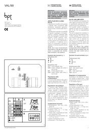
Il monitor è predisposto anche per<br />
operare in tre modi speciali che<br />
possono essere selezionati<br />
mediante i ponticelli 2, 3 e 4 (fig. 6)<br />
come segue:<br />
D<br />
G<br />
NOTA. Innestando a fondo il ponticello<br />
sui due spinotti questi risultano collegati<br />
fra di loro e viene quindi stabilita<br />
la condiqione ON, mentre la condizione<br />
OFF viene ottenuta disinserendo<br />
il ponticello; in questo caso il<br />
ponticello viene inserito su uno solo<br />
spinotto che funge unicamente da<br />
supporto (vedi particolare di fig. 6).<br />
LED 3<br />
LED 2<br />
LED 1<br />
1<br />
1<br />
4<br />
I<br />
ISTRUZIONI PER<br />
L’INSTALLAZIONE<br />
AVVERTENZE<br />
PER L’INSTALLATORE<br />
Queste istruzioni devono essere<br />
allegate al derivato interno.<br />
• Funzionamento continuo (da utilizzare<br />
esclusivamente per funzioni<br />
di videocontrollo in impianti monofamiliari<br />
con telecamera, costantemente<br />
alimentata, separata dal<br />
posto esterno)<br />
Il monitor viene fornito con il dip-switch<br />
2 in posizione OFF. Per ottenere<br />
questo tipo di funzionamento è<br />
necessario portare il dip-switch in<br />
posizione ON.<br />
Lo spegnimento del monitor viene<br />
effettuato mediante l’interruttore D di<br />
fig. 1.<br />
3<br />
2<br />
1<br />
2<br />
ON<br />
OFF<br />
2<br />
P1<br />
3<br />
F1<br />
2<br />
9<br />
87654321<br />
<strong>10</strong><br />
11<br />
12<br />
13<br />
14<br />
15<br />
5<br />
4<br />
MONITOR PIATTO A COLORI<br />
CON CORNETTA VMC/<strong>10</strong>0.<strong>02</strong><br />
Monitor a colori LCD TFT da 3,5” (9<br />
cm). Standard video: PAL/NTSC.<br />
Compatibile con il sistema videocitofonico<br />
in bianco e nero.<br />
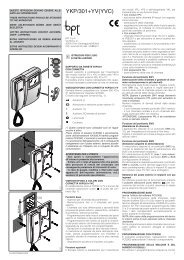
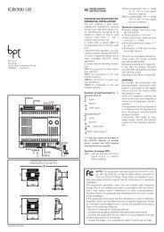
È munito dei seguenti comandi e<br />
segnalazioni (fig. 1):<br />
Acceso/spento-luminosità<br />
(comando D)<br />
Inserimento-selezione posto<br />
esterno<br />
Luce scale<br />
Apriporta<br />
• Aux 1 - Pulsante a disposizione<br />
per comandi supplementari<br />
•<br />
Aux 2 - Pulsante a disposizione<br />
per comandi supplementari<br />
G Regolazione saturazione<br />
colore<br />
LED 1<br />
Indicatore luminoso verde a<br />
disposizione per segnalazioni<br />
ausiliarie (allarmi, controlli,<br />
ecc.).<br />
• Accensione contemporanea di<br />
più monitor in parallelo mediante<br />
unica chiamata<br />
Per ottenere questo tipo di funzionamento<br />
da un gruppo di monitor collegati<br />
alla stessa chiamata è necessario:<br />
a) assicurarsi che su uno solo dei<br />
monitor il dip-switch 3 sia in posizione<br />
ON;<br />
b) portare in posizione OFF il dipswitch<br />
3 dei rimanenti monitor.<br />
• Spegnimento del monitor<br />
mediante il comando apriporta<br />
a) Impianti con alimentatore<br />
VA/<strong>10</strong>0<br />
Il monitor si spegne normalmente a<br />
fine temporizzazione (dip-switch 4 in<br />
posizione OFF). Portando lo stesso<br />
dip-switch in posizione ON il monitor<br />
verrà spento mediante l’azionamento<br />
del comando apriporta.<br />
b) Impianti con alimentatore<br />
VA/<strong>10</strong>0.01<br />
Il dip-switch 4 deve essere in posizione<br />
OFF.<br />
Lo spegnimento del monitor è selezionato<br />
tramite il dip-switch 2 dell’alimentatore<br />
VA/<strong>10</strong>0.01.<br />
E<br />
BPT S.p.A.<br />
Via Roma, 41<br />
30<strong>02</strong>0 Cinto Caomaggiore-VE-Italy<br />
www.bpt.it-info@bpt.it<br />
<strong>10</strong>.20<strong>08</strong>/<strong>24854600</strong><br />
3<br />
6<br />
LED 2<br />
LED 3<br />
Indicatore luminoso giallo a<br />
disposizione per segnalazioni<br />
ausiliarie (allarmi, controlli,<br />
ecc.).<br />
Indicatore luminoso rosso a<br />
disposizione per segnalazioni<br />
ausiliarie (allarmi, controlli,<br />
ecc.).<br />
I pulsanti Aux 1 e Aux 2 chiudono<br />
rispettivamente i morsetti 11 e 12<br />
verso il negativo (–) dell’alimentazione<br />
(24V <strong>10</strong>0mA max.).<br />
I LED 1 e 2 vengono attivati collegando<br />
i rispettivi morsetti 13 e 14 al negativo<br />
(–) dell’alimentazione (morsetto<br />
5) tramite un dispositivo del servizio<br />
controllato.<br />
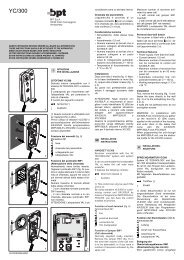
Il fusibile F1 di protezione tipo T 500<br />
mA è situato sul circuito stampato<br />
(fig. 6).<br />
(Fusibile: F = rapido, T = ritardato).<br />
AVVERTENZE PER L’UTENTE<br />
- Non aprire o manomettere l’apparecchio;<br />
all’interno é presente alta<br />
tensione.<br />
- Evitare urti o colpi all’apparecchio<br />
che potrebbero provocare la rottura<br />
del cinescopio con conseguente<br />
proiezione di frammenti di vetro.<br />
- In caso di guasto, modifica o intervento<br />
sugli apparecchi dell’impianto<br />
(alimentatore, ecc.) avvalersi di personale<br />
specializzato.<br />
Segnale di chiamata<br />
Il volume della nota di chiamata dal<br />
posto esterno è regolabile mediante il<br />
potenziometro P1 di fig. 6.<br />
In caso di impianti con chiamata temporizzata<br />
(alimentatore mod.<br />
VA/<strong>10</strong>0.01) l’interruzione della chiamata<br />
stessa si verifica alla fine del<br />
tempo programmato, o sollevando la<br />
cornetta o premendo uno qualsiasi<br />
dei pulsanti .<br />
Funzione dei morsetti (fig. 6)<br />
1 segnale video<br />
2 schermo segnale video<br />
( 1 )<br />
3 segnale video<br />
4 schermo segnale video<br />
5 – 14 ÷ 17,5<br />
6 + alimentazione monitor<br />
7 chiamata<br />
8 audio al monitor<br />
9 audio al posto esterno<br />
<strong>10</strong> uscita +11,5V (50mA max.)<br />
oppure ingresso per teleaccensione<br />
collegando il morsetto a<br />
+15 ÷ 17,5V<br />
11 Aux 1<br />
12 Aux 2<br />
13 LED 1 (verde)<br />
14 LED 2 (giallo)<br />
15 LED 3 (rosso)<br />
( 1 ) Resistenza di chiusura da 75 Ω<br />
se la linea non prosegue.<br />
NOTA. Effettuare i collegamenti<br />
1
all’apparecchio seguendo gli schemi<br />
d’impianto realizzati con il monitor<br />
VM/<strong>10</strong>6.<br />
Caratteristiche tecniche<br />
• Standard video: PAL/NTSC.<br />
• Display: LCD TFT a colori 3,5” (9<br />
cm).<br />
• Alimentazione: 14 ÷ 17,5Vcc.<br />
• Assorbimento: max. 350 mA (5mA<br />
a riposo).<br />
• Assorbimento per ogni LED: 7mA.<br />
• Ingresso video: 1 Vpp su 75 Ω.<br />
• Impedenza d’ingresso video: >15<br />
KΩ.<br />
• Segnale di chiamata: bitonale,<br />
regolabile.<br />
• Aux 1 e Aux 2: contatti normalmente<br />
aperti verso il negativo (–)<br />
dell’alimentazione (24V <strong>10</strong>0mA<br />
max.).<br />
• Temperatura di funzionamento: da<br />
0 °C a +35 °C.<br />
• Dimensioni: 195 x 230 x 72 mm.<br />
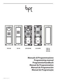
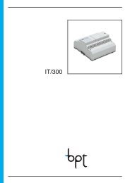
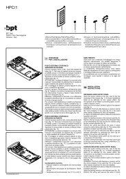
INSTALLAZIONE<br />
Spostare il dispositivo di bloccaggio<br />
come indicato in fig. 2A. Sfilare il supporto<br />
in acciaio dal monitor e fissarlo,<br />
ad un’altezza adatta all’utente,<br />
mediante tasselli e viti in dotazione.<br />
Rispettare l’indicazione ALTO e fare<br />
in modo che l’uscita dei cavi dalla<br />
parete coincida con l’apposito passaggio<br />
E del supporto (fig. 3).<br />
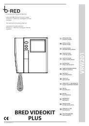
Svitare le due viti di fissaggio e<br />
togliere la parte sinistra del mobile<br />
(fig. 4). Passare i conduttori attraverso<br />
la feritoia sul fondo del monitor,<br />
posizionare il monitor nel supporto da<br />
parete ed innestarlo al supporto stesso<br />
con un movimento verso il basso<br />
(fig. 5).<br />
Per evitare cadute dal monitor a<br />
causa di urti accidentali, bloccare il<br />
monitor stesso al supporto da parete<br />
spostando verso destra (fig. 2B) il<br />
dispositivo di bloccaggio. Procedere<br />
nella maniera opposta in caso di<br />
smontaggio del monitor.<br />
Effettuare i collegamenti seguendo lo<br />
schema. Rimettere la parte sinistra<br />
del mobile fissandolo con le due viti.<br />
GB INSTALLATION<br />
INSTRUCTIONS<br />
WARNING<br />
FOR THE INSTALLER<br />
These instructions should be attached<br />
to the receiver.<br />
VMC/<strong>10</strong>0.<strong>02</strong> INTERCOM<br />
COLOUR FLAT MONITOR<br />
WITH HANDSET<br />
LCD TFT 3.5” (9 cm) colour monitor.<br />
Video standard: PAL/NTSC.<br />
It is compatible to black and white<br />
BPT video entry control.<br />
It is equipped with the following controls<br />
and warnings, figure 1:<br />
Thumb-wheel D to switch the<br />
monitor ON/OFF and for the<br />
brightness control.<br />
Button to bring the monitor<br />
live and manual sequencing<br />
of any additional panel/<br />
camera.<br />
Button to turn on stairs light.<br />
Door lock release button.<br />
• Aux 1 - Button for auxiliary<br />
services as required.<br />
•<br />
G<br />
2<br />
Aux 2 - Button for auxiliary<br />
services as required.<br />
Potentiometer to regulate<br />
saturation colour.<br />
LED 1<br />
LED 2<br />
LED 3<br />
Green LED can be used to<br />
indicate an external function.<br />
Yellow LED can be used to<br />
indicate an external function.<br />
Red LED can be used to<br />
indicate an external function.<br />
Switches Aux 1 and Aux 2 are normally<br />
open, when actuated the contacts<br />
close on –0V DC. Max. current<br />
demand <strong>10</strong>0mA at 24V.<br />
To activate LED 1 and LED 2 line 13<br />
and 14 should be connected via an<br />
external switch device which is common<br />
to terminal 5 of the system, 0V<br />
DC.<br />
The monitor is protected by the slow<br />
blow fuse F1 - T 500 mA - mounted<br />
on monitor’s printed card, figures 6.<br />
(Fuse: F = fast, T = slow).<br />
WARNINGS FOR THE USER<br />
- Please do not open or tamper the<br />
device (high voltage!).<br />
- Please avoid knocking or bumping<br />
the apparatus as it could result in the<br />
breakage of the picture tube and the<br />
consequent projection of glass fragments.<br />
- In the case of breakdown or modification<br />
of the apparatus of the<br />
system (such as power supplier …)<br />
please contact a specialized maintenance<br />
service.<br />
Three special monitor operation<br />
modes can be chosen by means of<br />
jumpers 2, 3 and 4 located on<br />
monitor’s printed card, figure 6.<br />
NOTE. The ON position is achieved<br />
by inserting the jumper across 2 pins<br />
to assure alectric connection. The<br />
jumper must be inserted on 1 pin only<br />
when OFF position is required.<br />
See detail on top of figure 6.<br />
• Monitor in constant mode<br />
For use only in single house installations<br />
as close circuit television<br />
system with camera always powered<br />
and separated from entry panel.<br />
VMC/<strong>10</strong>6 is supplied from the factory<br />
with jumper 2 in the OFF position.<br />
The constant mode is achieved with<br />
jumper 2 set to ON position.<br />
The monitor can only be switched off<br />
by thumb-wheel switch D, figure 1.<br />
• Activation of more monitors by<br />
the same call<br />
Jumper 3 is normally kept in the ON<br />
position, this way the call line loop is<br />
closed. If more monitors must be activated<br />
by the same call, leave only<br />
one with the jumper 3 in the ON position,<br />
all other monitors must have the<br />
jumper 3 in the OFF position.<br />
• Monitor/system turned off on<br />
door release<br />
a) Systems with VA/<strong>10</strong>0 main control<br />
unit<br />
Jumper 4 is normally kept in the OFF<br />
position. In this position the monitor is<br />
turned off automatically by the<br />
system timer. Whit Jumper 4 in the<br />
ON position the monitor is turned off<br />
by pressing the door lock release<br />
button.<br />
b) Systems with VA/<strong>10</strong>0.01 main<br />
control unit<br />
Jumper 4 must be in the OFF position.<br />
Use dip-switch 2 of the VA/<strong>10</strong>0.01<br />
main control unit to turn off the monitor.<br />
Call tone<br />
It is possible to regulate the call tone<br />
level from the entry panel by adjusting<br />
the trimmer P1, figure 6.<br />
System using main control unit<br />
VA/<strong>10</strong>0.01 has a timed call feature.<br />
The call stops either when the handset<br />
is lifted or when any<br />
button is pressed.<br />
Function of each terminal, figure 6<br />
1 video signal<br />
2 video signal shield<br />
( 1 )<br />
3 video signal<br />
4 video signal shield<br />
5 – 14 ÷ 17.5V<br />
6 + supply voltage to monitor<br />
7 call<br />
8 audio to monitor<br />
9 audio to entry panel<br />
<strong>10</strong> 11.5V DC voltage output ( 2 )<br />
or input to turn on monitor when<br />
connected to positive voltage<br />
system (+15 ÷ 17.5V DC)<br />
11 Aux 1<br />
12 Aux 2<br />
13 LED 1 (green)<br />
14 LED 2 (yellow)<br />
15 LED 3 (red)<br />
16 audio intercom.<br />
17 audio intercom.<br />
18 intercom call code<br />
( 1 ) 75 Ω closing resistance if video<br />
line stops here<br />
( 2 ) This voltage output is available<br />
for the time the monitor is operating.<br />
Max. current demand should not<br />
exceed 50mA.<br />
NOTE. Connect wires to terminals in<br />
accordance to VM/<strong>10</strong>0 diagrams.<br />
Technical features<br />
• Video standard: PAL/NTSC.<br />
• Display: LCD TFT 3.5” (9 cm)<br />
colour.<br />
• Supply voltage: 14 ÷ 17.5V DC.<br />
• Max. current demand: 350 mA<br />
(5mA quiescent).<br />
• Current demand per LED: 7mA.<br />
• Video input: 1 Vpp on 75 Ω.<br />
• Video input impedance: >15 KΩ.<br />
• Call signal: electronic dual tone,<br />
the call volume can be regulated.<br />
• Aux 1 and Aux 2: normally open<br />
switch, when actuated the contact<br />
closes to 0V DC. Current demand<br />
should not exceed <strong>10</strong>0mA at 24V.<br />
• Working temperature range: from<br />
0 °C to +35 °C.<br />
• Dimensions: 195 x 230 x 72 mm.<br />
INSTALLATION<br />
Slide the locking latch as shown in<br />
figure 2A. Slide the steel frame out,<br />
and fix it on the wall at a suitable height<br />
by using the screws and retainers<br />
included in the pack.<br />
Please, pay attention to place the<br />
frame with the indication TOP in<br />
upper position, and make the hol E,<br />
figure 3, to coincide with the cable<br />
junction box.<br />
Unscrew the two screws, figure 4,<br />
and take the left part of the housing<br />
out.<br />
Pass the cables through the slot at<br />
the bottom of the housing, place the<br />
monitor on the steel frame and fix it<br />
by sliding it downwards, figure 5. To<br />
avoid undesired falls of the monitor<br />
caused by accidental shocks, lock it<br />
by sliding the latch, figure 2B, to the<br />
right.<br />
Proceed the opposite way to<br />
unmount the monitor.<br />
Make all connections and fix the<br />
cover of the left part of the housing<br />
with the two screws.<br />
D<br />
INSTALLATIONS-<br />
ANLEITUNG<br />
ACHTUNG!<br />
NUR FÜR INSTALLATEUR<br />
Diese Anleitungen müßen jede der<br />
Sprechstelle begleiten.<br />
FARBFLACHMONITOR<br />
MIT HÖRER VMC/<strong>10</strong>0.<strong>02</strong><br />
Farbmonitor LCD TFT mit 3,5” (9 cm).<br />
Standardvideo: PAL/NTSC.<br />
Kompatibel zum BPT s/w Video-<br />
System <strong>10</strong>0.<br />
Mit folgenden Schalt- und Anzei-geelementen<br />
(Abb. 1):<br />
EIN/AUS, Helligkeit (Taste D).<br />
Taste zur Bildeinund Kameraweiterschaltung<br />
von zusätzlichen<br />
Kamerastellen.<br />
Taste für Treppenlicht.<br />
Türöffnertaste.<br />
• Aux 1 - Taste für zusätzlich<br />
gewünschte Serviceschaltung.<br />
•<br />
Aux 2 - Taste für zusätzlich<br />
gewünschte Serviceschaltung.<br />
G Regulierung der Farb-<br />
Saturation<br />
LED 1<br />
LED 2<br />
LED 3<br />
Grüne LED kann für die Anzeige<br />
einer externen Funktion<br />
verwendet werden.<br />
Gelbe LED kann für die Anzeige<br />
einer externen Funktion<br />
verwendet werden.<br />
Rote LED kann für die Anzeige<br />
einer externen Funktion<br />
verwendet werden.<br />
Die Taste Aux 2 (24V, <strong>10</strong>0mA max.)<br />
verbinden Klemme 12 mit minus Pol<br />
des Netzgerätes.<br />
Die LED 2 zu aktivieren, sind deren,<br />
Anschlüsse, d.h. 14 über das Gerät,<br />
dessen Funktion angezeigt werden<br />
soll (z.B. Relaise) mit dem Klemmanschluss<br />
5 -0V DC zu verbinden.<br />
Der Monitor wird durch die Sicherung<br />
F1 - T 500 mA - angebracht auf der<br />
Monitoplatine, geschützt (Abb. 6).<br />
(Sicherung: F = flink, T = träge).<br />
HINWEISE FÜR DEN NUTZER<br />
- Bitte Gerät nicht öffnen oder aufbrechen<br />
(hohe Spannung!).<br />
- Zur Vermeidung eines Bildröhrenbruchs,<br />
Stösse und Schläge unterlassen.<br />
- Bei Störungen, Änderungen oder<br />
Reparaturen an den Geräten<br />
(Netzgerät, usw.) nur an Spezialisten<br />
wenden.<br />
Durch die auf der Monitorplatine<br />
befindlichen Steckbrücken 2, 3 und<br />
4 (Abb. 6) können drei spezielle<br />
Monitorfunktionen gewählt werden.<br />
Die ON-Position ist erreichbar, wenn<br />
die Steckbrücken über 2 Pin erfolgt.<br />
Stecker voll nach unten drücken.<br />
Wenn OFF-Position gewünscht wird,<br />
ist der Stecker nur über einen Pin zu<br />
schalten. Nähere Details, siehe Abb.<br />
6 oben.<br />
• Monitor in Dauerbetrieb<br />
Nur in Einfamilienhaus-Installation<br />
möglich, als Überwachungssystem<br />
mit von der Außenstation abgesetzter<br />
Kamera.<br />
VMC/<strong>10</strong>0 wird werkseitig mit Steckbrücke<br />
2 in OFF-Position geliefert.<br />
Für Dauerbetrieb ist der Steck-
ücke 2 in ON-Position zu stellen.<br />
Der Monitor kann nur über den<br />
Drehschalter D, Abb. 1 abgeschaltet<br />
werden.<br />
• Einschaltung von Monitor mit<br />
gleichem Anruf<br />
Die Steckbrücke 3 ist normalerweise<br />
in ON-Position geschaltet, dadurch<br />
ist die Ruflinie geschlossen.<br />
Wenn mehr Monitore mit einem Anruf<br />
eingeschaltet werden sollen, ist nur<br />
ein Monitor mit Steckbrücke 3 in ON-<br />
Position zu schalten und alle anderen<br />
in OFF-Position.<br />
• Monitor-/Systemausschaltung<br />
durch Türöffnertaste<br />
a) Anlagen mit Netzgerät VA/<strong>10</strong>0<br />
Steckbrücke 4 ist normalerweise in<br />
OFF-Position und das System wird<br />
durch automatischen System-Timer<br />
abgeschaltet.<br />
Mit Steckbrücke 4 in ON-Position<br />
schaltet das System ab, wenn die<br />
Türöffnertaste am Monitor betätigt wird.<br />
b) Anlagen mit Netzgerät VA/<strong>10</strong>0.01<br />
Steckbrücke 4 muß auf OFF-Position<br />
geschaltet sein.<br />
Abschalten der Innenabzweigung<br />
über Kodierschalter 2 an Netzgerät<br />
VA/<strong>10</strong>0.01.<br />
Rufton<br />
Die Lautstärke des Ruftones kann<br />
über den Trimmer P1 eingestellt werden<br />
(Abb. 6).<br />
Bei Anlagen mit zeitgeschalttetem<br />
Ruf (Netzgerät Mod. VA/<strong>10</strong>0.01)<br />
erfolgt die Unterbrechung des<br />
Ruftones nach Ablauf der programmierten<br />
Zeit oder durch Abheben des<br />
Hörers oder auch durch Drücken<br />
einer der Tasten .<br />
Belegung der Klemmleisten (Abb. 6)<br />
1 Videosignal<br />
2 Videosignalabschirm.<br />
( 1 )<br />
3 Videosignal<br />
4 Videosignalabschirm.<br />
5 – 14 ÷ 17,5V<br />
6 + Monitorversorgung<br />
7 Anruf<br />
8 Ton zum Monitor<br />
9 Ton zur Außenstelle<br />
<strong>10</strong> Ausgang +11,5V (max. 50mA)<br />
oder Eingang für die Ferneinschaltung<br />
durch Anschluß der<br />
Klemme an +15 ÷ 17,5V<br />
11 Aux 1<br />
12 Aux 2<br />
13 LED 1 (grüne)<br />
14 LED 2 (gelb)<br />
15 LED 3 (rot)<br />
( 1 ) 75 Ω Abschlußwiderstand bei<br />
Nichtfortführung der Linie.<br />
ANMERKUNG. Die Anschlüsse am<br />
Gerät nach den Schaltbildern von<br />
Monitor VM/<strong>10</strong>0 vornehmen.<br />
Technische Daten<br />
• Standardvideo: PAL/NTSC.<br />
• Display: LCD TFT farbig 3,5” (9 cm).<br />
• Betriebsspannung: 14÷17,5V DC.<br />
• Stromaufnahme: max. 350 mA<br />
(5mA Ruhestrom).<br />
• Stromaufnahme für jede LED:<br />
7mA.<br />
• Videoeingang: 1 Vss auf 75 Ω.<br />
• Video-Eingangsimpedanz: > 15<br />
KΩ.<br />
• Rufsignal: Zweitonsignal, einstellbar.<br />
• Aux 1 und Aux 2: Schließkontakte<br />
zum Anschluß an die Minusklemme<br />
der Stromversorgung (24V<br />
<strong>10</strong>0mA max.).<br />
• Betriebstemperatur: von 0 °C bis<br />
+35 °C.<br />
• Abmessungen: 195 x 230 x 72 mm.<br />
INSTALLATION<br />
Verriegelung erfolgt gemäß<br />
Darstellung Abb. 2A, Stahlrahmen<br />
vom Monitor entfernen und unter<br />
Beachtung der Oberseite an der<br />
Wand, auf eine angemessene Höhe,<br />
anbringen.<br />
Unter Vervendung der beigefügten<br />
Dübel und Schrauben montieren,<br />
Kabel durch Öffnung E führen (Abb.<br />
3).<br />
2 Befestigungsschrauben lösen und<br />
Hörergabel entfernen (Abb. 4).<br />
Kabeldurchbrücke für Kabeldurchführung<br />
entfernen und Kabel einziehen<br />
(Abb. 5).<br />
Monitor auf Halterung aufsetzen und<br />
Verriegelung nach rechts schieben,<br />
Abb. 2B, um eine Beschädigung des<br />
unbefestigten Monitors zu vermeiden.<br />
Anschlüsse gem. Diagramm verbinden.<br />
Hörer und Hörergabel anbringen<br />
und mit 2 Schrauben befestigen.<br />
F<br />
INSTRUCTIONS<br />
POUR L’INSTALLATION<br />
PRECAUTIONS<br />
POUR L’INSTALLATEUR<br />
Cettes instructions doivent accompagner<br />
chaque poste intérieur.<br />
RECEPTEUR VIDEO PLAT<br />
EN COULEURS REF. VMC/<strong>10</strong>0.<strong>02</strong><br />
Moniteur à couleurs LCD TFT de 3,5”<br />
(9 cm). Standard vidéo: PAL/NTSC.<br />
Compatible avec le système vidéoportier<br />
en blanc et noir.<br />
Doté des commandes et signalisations<br />
suivantes (fig. 1):<br />
Marche/Arrêt - réglage de la<br />
luminosité (commande D).<br />
Mise en marche-sélection<br />
des postes extérieurs.<br />
Commande de minuterie.<br />
Commande ouvre-porte<br />
(gâche-électrique).<br />
• Bouton-poussoir disponible<br />
pour commandes auxiliaires<br />
(Aux 1).<br />
•<br />
G<br />
LED 1<br />
Bouton-poussoir disponible<br />
pour commandes auxiliaires<br />
(Aux 2).<br />
Réglage saturation du couleur.<br />
Voyant lumineux vert disponible<br />
pour signalisations<br />
auxiliaires (alarmes, contrôles,<br />
etc.).<br />
LED 2 Voyant lumineux jaune<br />
disponible pour signalisations<br />
auxiliaires (alarmes,<br />
contrôles, etc.).<br />
LED 3 Voyant lumineux rouge<br />
disponible pour signalisations<br />
auxiliaires (alarmes,<br />
contrôles, etc.).<br />
Les boutons Aux 1 et Aux 2 (dont le<br />
pouvoir de coupure est de 24V,<br />
<strong>10</strong>0mA maxi) relient respectivement<br />
les bornes 11 et 12 au négatif (–) de<br />
l’alimentation.<br />
Pour obtenir l’allumage des LED 1 et<br />
2, relier respectivement les bornes 13<br />
et 14 à la borne 5 (négatif de l’alimentation<br />
en courant continu) par le<br />
dispositif du service auxiliaires à contrôler.<br />
Le fusible F1 de protection du type T<br />
500 mA est placé sur le circuit<br />
imprimé (fig. 6).<br />
(Fusible: F = rapide, T = retardé).<br />
PRECAUTIONS<br />
POUR L’USAGER<br />
- Ne pas ouvrir l’appareil: attention<br />
haute tension!<br />
- Eviter les chocs qui pourraient provoquer<br />
l’implosion du tube cathodique<br />
et la projection de fragments de verre.<br />
- En cas de défaut, de modification<br />
ou d’intervention sur les appareils de<br />
l’installation (alimentation, etc.), s’adresser<br />
exclusivement au personnel<br />
spécialisé.<br />
Le moniteur est équipé de trois<br />
cavaliers 2, 3 et 4 (fig. 6) qui permettent<br />
la sélection des trois<br />
modes spéciales de fonctionnement<br />
suivants:<br />
NOTE. En éclipsant à fond le cavalier<br />
sur les deux broches, on les relie<br />
entre elles établissant la condition<br />
ON, tandis que la condition OFF est<br />
obtenue en ôtant le cavalier même;<br />
dans ce cas on loge le cavalier sur<br />
une seule broche qui sert uniquement,<br />
dans ce cas, de support (voir<br />
détail à la fig. 6).<br />
• Fonctionnement en service continu<br />
(à utiliser exclusivement en<br />
vidéo-surveillance dans les installations<br />
villa et avec télécaméra, alimentée<br />
en permanence, séparée<br />
du poste extérieur)<br />
Le moniteur est fourni avec le cavalier<br />
2 en position OFF.<br />
Cet fonctionnement peut être établi<br />
en plaçant ledit cavalier en position<br />
ON.<br />
L’extinction du moniteur s’obtient à<br />
l’aide de l’interrupteur marche/arrêtluminosité<br />
D (fig. 1).<br />
• Allumage simultané de plusieurs<br />
moniteurs en parallèle sur signal<br />
d’appel unique<br />
Pour obtenir la mise en marche d’un<br />
groupe de moniteurs reliés sur un<br />
seul appel placer le cavalier 3 sur un<br />
seul des moniteurs en position ON;<br />
les autres moniteurs devront avoir le<br />
cavalier 3 en position OFF.<br />
• Extinction du moniteur par la<br />
commande ouvre-porte<br />
a) Installations avec alimentation<br />
VA/<strong>10</strong>0<br />
Le moniteur s’arrêt normalement<br />
jusqu’à la fin de la temporisation<br />
(cavalier 4 en position OFF).<br />
En plaçant le même cavalier en position<br />
ON, l’arrêt du moniteur est obtenu<br />
par la commande d’ouverture de<br />
la gâche.<br />
b) Installations avec alimentation<br />
VA/<strong>10</strong>0.01<br />
Le cavalier 4 doit être positionné sur<br />
OFF.<br />
On sélectionne l’interruption du moniteur<br />
au moyen du dip-switch 2 de l’alimentation<br />
VA/<strong>10</strong>0.01.<br />
Signal d’appel<br />
L’intensité de la note d’appel provenant<br />
du poste extérieur est réglable à<br />
l’aide du potentiomètre P1 de la fig.<br />
6.<br />
En cas d’installations avec appel<br />
temporisé (alimentation mod.<br />
VA/<strong>10</strong>0.01) l’interruption de l’appel<br />
peut être vérifié à la fin de la durée<br />
programmé, en soulevant le récepteur<br />
ou en appuyant sur l’une des<br />
touches .<br />
Fonction des bornes (fig. 6)<br />
1 signal vidéo<br />
2 blindage signal vidéo<br />
( 1 )<br />
3 signal vidéo<br />
4 blindage signal vidéo<br />
5 – 14 ÷ 17,5V alimentation<br />
6 + du moniteur<br />
7 appel<br />
8 audio au moniteur<br />
9 audio au poste extérieur<br />
<strong>10</strong> sortie +11,5V (50mA max.) ou<br />
entrée pour télé-allumage en<br />
branchant la borne à +15 ÷<br />
17,5V<br />
11 Aux 1<br />
12 Aux 2<br />
13 LED 1 (vert)<br />
14 LED 2 (jaune)<br />
15 LED 3 (rouge)<br />
( 1 ) Résistence 75 Ω de fin de ligne.<br />
NOTE. Effectuer les branchements à<br />
l’appareil en suivant les schémas d’installation<br />
réalisés avec le moniteur<br />
VM/<strong>10</strong>0.<br />
Caractéristiques techniques<br />
• Standard vidéo: PAL/NTSC.<br />
• Écran: LCD TFT à couleurs 3,5” (9<br />
cm).<br />
• Alimentation: 14 ÷ 17,5Vcc.<br />
• Consommation: 350 mA maxi<br />
(5mA à repos).<br />
• Consommation pour chaque LED:<br />
7mA.<br />
• Entrée vidéo: 1,5Vpp sur 75 Ω.<br />
• Impédance d’entrée vidéo: >15<br />
KΩ.<br />
• Signal d’appel: bitonale réglable.<br />
• Aux 1 et Aux 2: contacts normalement<br />
ouverts sur le négatif de l’alimentation<br />
(pouvoir de coupure:<br />
24V <strong>10</strong>0mA maxi).<br />
• Température de fonctionnement:<br />
de 0 °C à +35 °C.<br />
• Dimensions: 195 x 230 x 72 mm.<br />
INSTALLATION<br />
Dégager le dispositif de verrouillage<br />
comme indiqué à la fig. 2A, ôter de<br />
l’appareil le support mural en acier et<br />
le fixer à un’hauteur apte pour l’utilisateur<br />
à l’aide des quatre vis fournies.<br />
Il est impératif que l’indication HAUT<br />
soit respectée et que la sortie des<br />
câbles du mur soit en coïncidence<br />
avec le passage correspondant E du<br />
support comme indiqué à la fig. 3.<br />
Dévisser les deux vis de fixation et<br />
ôter la partie gauche de l’appareil<br />
(fig. 4).<br />
Passer les conducteurs à travers l’ouverture<br />
située au fond du moniteur,<br />
loger le moniteur à son support mural<br />
et l’enclipser en le glissant vers le<br />
bas (fig. 5).<br />
Bloquer l’appareil à son support en<br />
déplaçant vers le droite l’élément de<br />
verrouillage indiqué à la fig. 2B afin<br />
d’éviter tout risque de chute accidentelle.<br />
Procéder de la façon inverse pour le<br />
démontage du moniteur.<br />
Après avoir effectué les connexions<br />
suivant le schéma de raccordement,<br />
remonter la partie gauche et la fixer à<br />
l’aide de ses deux vis.<br />
3
E<br />
INSTRUCCIONES<br />
PARA LA INSTALACION<br />
ADVERTENCIA<br />
AL INSTALADOR<br />
Estas instrucciones se deben<br />
anexar al derivado interno.<br />
MONITOR COLOR PLANO<br />
CON AURICULAR VMC/<strong>10</strong>0.01<br />
Monitor en color LCD TFT de 3,5” (9<br />
cm). Estándar de vídeo: PAL/NTSC.<br />
Compatible con el sistema de videoportero<br />
en blanco y negro.<br />
Está dotado de los siguientes mandos<br />
y señalizaciones (fig. 1):<br />
Encendido/apagado-luminosidad<br />
(mando D).<br />
Habilitación-selección placa<br />
exterior.<br />
Luz de la escalera.<br />
Abrepuerta.<br />
• Aux 1 - Pulsador disponible<br />
para mandos suplementarios.<br />
•<br />
G<br />
LED 1<br />
LED 2<br />
Aux 2 - Pulsador disponible<br />
para mandos suplementarios.<br />
Regulación del color.<br />
Indicador luminoso verde<br />
disponible para señalizaciones<br />
auxiliares (alarmas, controles,<br />
etc.).<br />
Indicador luminoso amarillo<br />
disponible para señalizaciones<br />
auxiliares (alarmas, controles,<br />
etc.).<br />
LED 3 Indicador luminoso rojo<br />
disponible para señalizaciones<br />
auxiliares (alarmas, controles,<br />
etc.).<br />
Los pulsadores Aux 1 y Aux 2 cierran<br />
respectivamente los bornes 11 y 12<br />
hacia el negativo (−) de la alimentación<br />
(24V <strong>10</strong>0mA máx.).<br />
Los LED 1 y 2 se activan conectando<br />
los correspondientes bornes 13 y 14<br />
al negativo (−) de la alimentación<br />
(borne 5) mediante un dispositivo del<br />
servicio controlado.<br />
El fusible F1 de protección tipo T 500<br />
mA está ubicado en el circuito impreso<br />
(fig. 6).<br />
(Fusibile: F = rápido, T = retardado).<br />
ADVERTENCIAS<br />
PARA EL USUARIO<br />
- No abrir ni manipular el aparato: en<br />
el interior hay alta tensión.<br />
- Evitar choques y golpes al aparato<br />
que puedan causar la implosión del<br />
tubo catódico y protección de fragmentos<br />
de vidro.<br />
- En caso de avería o necesidad de<br />
modificación o intervención sobre los<br />
aparatos de la instalación (alimentador,<br />
etc.) dirigirse al personal especializado.<br />
El monitor está preparado para<br />
funcionar también en tres modos<br />
especiales, que se pueden seleccionar<br />
mediante los puentes 2, 3 y<br />
4 de la fig. 6, a saber:<br />
NOTA. Insertando a fondo el puente<br />
en las dos clacijas, éstas se conectan<br />
entre sé y se establece la condición<br />
ON.<br />
Inhabilitando el puente se determina<br />
la condición OFF; en este caso, el<br />
mismo se inserta en una sola clavija,<br />
que hace únicamente de soporte<br />
(fig. 6).<br />
4<br />
• Funcionamiento continuo (destinado<br />
exclusivamente a funciones<br />
de videocontrol en equipos<br />
monofamiliares con cámara constantemente<br />
alimentada y separada<br />
de la placa exterior)<br />
El monitor se entrega con el puente 2<br />
en posición OFF. Para obtener este<br />
tipo de funcionamiento es necesario<br />
colocarlo en la posición ON.<br />
El monitor se apaga mediante el<br />
interruptor D de la fig. 1.<br />
• Encendido simultáneo de varios<br />
monitores en paralelo mediante<br />
una sola llamada<br />
Para obtener este tipo de funcionamiento<br />
de un grupo de monitores<br />
conectados a la misma llamada es<br />
necesario:<br />
a) asegurarse que en uno solo de los<br />
monitores el puente 3 está en la posición<br />
ON;<br />
b) colocar el puente 3 de los restantes<br />
monitores en la posición OFF.<br />
• Apagado del monitor mediante<br />
el mando abrepuerta<br />
a) En equipos con alimentador<br />
VA/<strong>10</strong>0<br />
El monitor se apaga normalmente al<br />
final de la temporización con el puente<br />
4 en la posición OFF.<br />
Colocando el mismo puente en la<br />
posición ON, el monitor se apaga al<br />
accionarse el mando abrepuerta.<br />
b) En equipos con alimentador<br />
VA/<strong>10</strong>0.01<br />
El puente 4 se coloca en la posición<br />
OFF.<br />
El apagado del monitor se puede<br />
seleccionar mediante el dip-switch 2<br />
del alimentador VA/<strong>10</strong>0.01.<br />
Señal de llamada<br />
El volumen de la nota de llamada<br />
desde la placa exterior se puede<br />
regular mediante el potenciómetro<br />
P1 (fig. 6).<br />
En caso de equipos con llamadas<br />
temporizadas (alimentador<br />
VA/<strong>10</strong>0.01), la interrupción de la<br />
misma se comprueba al final del<br />
tiempo programado, levantando el<br />
auricular o pulsando cualquier pulsador<br />
.<br />
Funciones de los bornes (fig. 6)<br />
1 señal de vídeo<br />
2 pantalla señal de vídeo<br />
( 1 )<br />
3 señal vídeo<br />
4 pantalla señal de vídeo<br />
5 − 14 ÷ 17,5V<br />
6 + alimentación monitor<br />
7 llamada<br />
8 audio al monitor<br />
9 audio a la placa exterior<br />
<strong>10</strong> salida +11,5V (50mA máx.) o<br />
entrada para encendido a<br />
distancia conectando el borne a<br />
+15 ÷ 17,5V<br />
11 Aux 1<br />
12 Aux 2<br />
13 LED 1 (verde)<br />
14 LED 2 (amarillo)<br />
15 LED 3 (rojo)<br />
( 1 ) Resistencia de cierre de 75 Ω si<br />
la línea no continúa.<br />
NOTA. Efectuar las conexiones al<br />
aparato según a los esquemas de<br />
instalación realizados para el monitor<br />
VM/<strong>10</strong>0.<br />
Características técnicas<br />
• Estándar de vídeo: PAL/NTSC.<br />
• Display: LCD TFT en color 3,5” (9<br />
cm).<br />
• Alimentación: 14 ÷ 17,5Vcc.<br />
• Absorción: máx. 350 mA (5mA en<br />
reposo).<br />
• Absorción por cada LED: 7mA.<br />
• Entrada vídeo: 1,5Vpp en 75 Ω.<br />
• Impedancia de entrada vídeo:<br />
>15 KΩ.<br />
• Señal de llamada: bitonal, regulable.<br />
• Aux 1 y Aux 2: contactos normalmente<br />
abiertos hacia el negativo<br />
(−) de la alimentación (24V <strong>10</strong>0mA<br />
máx.).<br />
• Temperatura de funcionamiento:<br />
de 0 °C a +35 °C.<br />
• Dimensiones: 195 x 230 x 72 mm.<br />
INSTALACION<br />
Desplazar el dispositivo de bloqueo<br />
como se indica en la fig. 2A. Extraer<br />
el soporte de acero del monitor y<br />
fijarlo, a una altura tal que resulte<br />
apta para el usuario, mediante los<br />
tacos y tornillos que se entregan de<br />
serie.<br />
Colocar hacia arriba el extremo que<br />
lleva la indicación ALTO y hacer que<br />
la salida de los cables de la pared<br />
coincida con el paso E del soporte<br />
(fig. 3).<br />
Aflojar los dos tornillos de fijación y<br />
quitar la parte izquierda del mueble<br />
(fig. 4). Pasar los conductores a<br />
través de la ranura practicada en el<br />
fondo del monitor, colocar este último<br />
en el soporte de pared y encajarlo en<br />
el mismo con un movimiento hacia<br />
abajo (fig. 5).<br />
A los fines de evitar que el monitor se<br />
caiga a causa de un golpe accidental,<br />
asegurarlo al soporte de pared<br />
desplazando hacia la derecha el<br />
dispositivo de bloqueo (fig. 2B).<br />
Para desmontar el monitor, proceder<br />
de manera inversa.<br />
realizar las conexiones, volver a montar<br />
la parte izquierda del mueble y<br />
fijarla con los dos tornillos.