
You also want an ePaper? Increase the reach of your titles
YUMPU automatically turns print PDFs into web optimized ePapers that Google loves.
<strong>B2MI0401</strong><br />
BPT Spa<br />
Centro direzionale e Sede legale<br />
Via Cornia, 1/b<br />
33079 Sesto al Reghena (PN) - Italia<br />
http://www.bpt.it - mailto: info@bpt.it<br />
<strong>B2MI0401</strong><br />
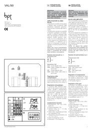
CARATTERISTICHE TECNICHE<br />
Alimentazione principale<br />
• Tensione di alimentazione<br />
12÷35 Vcc<br />
• Corrente assorbita max<br />
17 mA<br />
Il modulo è alimentabile ESCLUSIVAMENTE tramite il bus di sistema.<br />
Caratteristiche meccaniche<br />
• Peso 46 g.<br />
• Dimensioni<br />
85,5x60x21 mm.<br />
• Materiale del contenitore<br />
PC<br />
• Grado di protezione IP 30<br />
Caratteristiche climatiche<br />
• Temperatura di funzionamento 0÷40 °C<br />
• Massima umidità relativa in funzionamento 93% UR senza condensa<br />
• Temperatura di stoccaggio -10÷50 °C<br />
• Massima umidità relativa per lo stoccaggio 85% UR senza condensa<br />
L’alloggiamento del modulo <strong>B2MI0401</strong>all’interno del contenitore opzionale EB-<br />
TAM (fig. 3), oltre a garantire un grado di protezione complessiva superiore a IP 3X,<br />
permette la protezione da apertura e rimozione come previsto per il raggiungimento del<br />
livello di protezione II CEI 79-2 (con ingressi bilanciati).<br />
1<br />
<strong>B2MI0401</strong><br />
STATUS<br />
SW<br />
2<br />
1<br />
2<br />
3<br />
I<br />
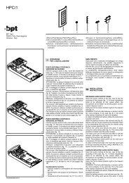
ISTRUZIONI PER<br />
L’INSTALLAZIONE<br />
MODULO 4 INGRESSI<br />
NON ALIMENTATI <strong>B2MI0401</strong><br />
Il dispositivo permette il collegamento al<br />
sistema di max 4 contatti magnetici per infissi,<br />
contatti a fune per tapparelle, contatti<br />
a vibrazione per rottura vetri, o di altri tipi<br />
di sensori con contatto di allarme NA o<br />
NC purchè alimentati esternamente o altri<br />
tipi di sensore che non necessitano di alimentazione.<br />
Il funzionamento del modulo<br />
è programmabile tramite l’unità centrale<br />
B2UC0001-B2UC0002 (vedi capitolo<br />
“Programmazione degli ingressi” del “Manuale<br />
Tecnico”).<br />
• Confezione: 1 istruzione, 1 modulo 4 ingressi<br />
<strong>B2MI0401</strong> e 8 resistenze da 2200Ω.<br />
ATTENZIONE.<br />
- I moduli vanno installati in luoghi protetti,<br />
al riparo da umidità e polvere.<br />
- Evitare di utilizzare, per il loro alloggiamento,<br />
una scatola ad incasso già adibita<br />
al passaggio di cavi per la tensione<br />
di rete 230 V.<br />
FUNZIONE DEI MORSETTI (fig. 1)<br />
BUS linea BUS<br />
I1 ingresso contatto 1<br />
T1 ingresso tamper 1<br />
–1 comune ingresso 1<br />
I2 ingresso contatto 2<br />
T2 ingresso tamper 2<br />
–2 comune ingresso 2<br />
I3 ingresso contatto 3<br />
T3 ingresso tamper 3<br />
–3 comune ingresso 3<br />
I4 ingresso contatto 4<br />
T4 ingresso tamper 4<br />
–4 comune ingresso 4<br />
17-02-10/24093802<br />
FUNZIONE DEL PONTICELLO SW<br />
(esclusione del tamper) (fig. 1)<br />
Il modulo è provvisto di un ponticello SW<br />
(fig.1) per escludere il tamper.<br />
Togliere il ponticello se si vuole utilizzare<br />
il dispositivo antiapertura e antimanomissione<br />
EBTAM (fig. 3).<br />
FUNZIONE DEL LED STATUS (fig. 1)<br />
Il Il modulo è provvisto di un led di stato<br />
di colore rosso con le seguenti funzioni:<br />
- lampeggio lento: funzionamento regolare;<br />
- lampeggio + suono del buzzer: identificazione<br />
in corso;<br />
- lampeggio veloce: anomalia, allarme o<br />
manomissione in corso;<br />
COLLEGAMENTI<br />
Nelle figure 4÷8 sono riportati alcuni<br />
esempi di collegamento dei sensori<br />
Brahms elencati in tabella 1.<br />
Qualora si volessero collegare altri tipi di<br />
sensore contattare il servizio assistenza<br />
Brahms.<br />
ATTENZIONE.<br />
La centrale prevede di fabbrica il collegamento<br />
dei sensori con contatto normalmente<br />
chiuso; qualora si voglia collegarli<br />
in modo diverso, è necessario programmare<br />
opportunamente gli ingressi onde<br />
evitare falsi allarmi.<br />
INSTALLAZIONE<br />
L’apparecchio può essere installato in<br />
scatole munite di guida DIN (EN 50022)<br />
(fig. 2).<br />
Le dimensioni del modulo sono compatibili<br />
con una scatola incasso da 3 o più<br />
moduli (fig. 2).<br />
Può essere inoltre installato a parete con<br />
il relativo dispositivo antiapertura e antimanomissione<br />
EBTAM (fig. 3).<br />
SMALTIMENTO<br />
Assicurarsi che il materiale d’imballaggio<br />
non venga disperso nell’ambiente,<br />
ma smaltito seguendo le norme vigenti<br />
nel paese di utilizzo del prodotto.<br />
Alla fine del ciclo di vita dell’apparecchio<br />
evitare che lo stesso venga disperso nell’ambiente.<br />
Lo smaltimento dell’apparecchiatura deve<br />
essere effettuato rispettando le norme<br />
vigenti e privilegiando il riciclaggio delle<br />
sue parti costituenti.<br />
Sui componenti, per cui è previsto lo<br />
smaltimento con riciclaggio, sono riportati<br />
il simbolo e la sigla del materiale.<br />
CONTATTI E SENSORI BRAHMS<br />
CONTATTI PER TAPPARELLE/SERRANDE<br />
CFSST contatto a fune precablato a due fili<br />
CONTATTI MAGNETICI<br />
CIO21 contatto magnetico incasso a 4 fili<br />
CIO22 contatto magnetico incasso a 2 fili<br />
CIO23 contatto magnetico incasso a 4 fili<br />
CIP31 contatto magnetico incasso a 4 fili<br />
CPA31 contatto magnetico per basculanti a 4 fili<br />
CSA11 contatto magnetico a vista a 4 morsetti<br />
CSA12 contatto magnetico a vista a 4 morsetti<br />
CSA31 contatto magnetico a vista a 4 fili<br />
CSP01 contatto magnetico a vista a 2 morsetti<br />
CSP02 contatto magnetico a vista a 2 morsetti<br />
CSP21 contatto magnetico a vista a 4 fili<br />
CXP31 contatto magnetico a vista a 2 fili<br />
SENSORI A VIBRAZIONE<br />
RIN01 sensore sfondamento muri/recinzioni a 4 fili<br />
RIN02 sensore sfondamento muri/recinzioni in box con 4 morsetti<br />
RVB02 sensore sfondamento vetri a 4 morsetti<br />
Tab. 1<br />
1
CFSST<br />
CIO21-CIO23-CIP31-CPA31-<br />
CSA31-CSP21-RIN01<br />
CSP01-CSP02<br />
CSA11-CSA12-RIN02-<br />
RVB02<br />
ALLARME<br />
ALLARME<br />
TAMPER<br />
<strong>B2MI0401</strong><br />
<strong>B2MI0401</strong><br />
<strong>B2MI0401</strong><br />
<strong>B2MI0401</strong><br />
BUS<br />
I1<br />
T1<br />
–1 I2<br />
T2<br />
BUS<br />
I1<br />
T1<br />
–1 I2<br />
T2<br />
BUS<br />
I1<br />
T1<br />
–1 I2<br />
T2<br />
BUS<br />
I1<br />
T1<br />
–1 I2<br />
T2<br />
4<br />
5<br />
6<br />
7<br />
TECHNICAL FEATURES<br />
Main power supply<br />
• Power supply voltage<br />
12÷35 V DC<br />
• Max input current<br />
17 mA<br />
The module can ONLY be powered by means of the system bus.<br />
Mechanical characteristics<br />
• Weight 46 g.<br />
• Dimensions:<br />
85.5x60x21 mm.<br />
• Container material<br />
PC<br />
• Protection rating:<br />
IP30<br />
Climatic characteristics<br />
• Operating temperature 0÷40 °C<br />
• Maximum relative humidity during operation 93% RH without condensation<br />
• Storage temperature -10÷+50 °C<br />
• Maximum relative humidity for storage 85% RH with no condensation<br />
The housing of the module <strong>B2MI0401</strong> in the EBTAM optional container (fig. 3), in addition<br />
to ensuring an overall degree of protection of greater than IP 3X, allows protection<br />
against opening and removal as required to attain the level of protection II CEI 79-2<br />
(with balanced inputs).<br />
CXP31-CIO22<br />
<strong>B2MI0401</strong><br />
BUS<br />
I1<br />
T1<br />
–1 I2<br />
T2<br />
8<br />
GB INSTALLATION<br />
INSTRUCTIONS<br />
MODULE WITH 4 NON-POWERED<br />
INPUTS <strong>B2MI0401</strong><br />
The device allows connection to the system<br />
of up to 4 magnetic contacts for door and<br />
window fixtures, cable contacts for blinds,<br />
vibration contacts for glass breakage, or<br />
other types of sensors with alarm contact<br />
NO or NC provided they powered externally<br />
or other types of sensors that do not require<br />
a power supply. The operation of the<br />
module is programmable using the central<br />
unit B2UC0001-B2UC0002 (see chapter<br />
“Programming inputs” of the “Technical<br />
Manual”).<br />
• Package: 1 instruction, 1 module with<br />
4 inputs <strong>B2MI0401</strong> and 8 resistors of<br />
2200Ω.<br />
ATTENTION.<br />
- The modules are to be installed in places<br />
that are protected from humidity and dust.<br />
- For housing them, avoid using a recess<br />
box which is already used for the passage<br />
of cables for 230V mains voltage.<br />
FUNCTION OF TERMINALS (fig. 1)<br />
BUS BUS line<br />
I1 contact 1 input<br />
T1 tamper input 1<br />
–1 common input 1<br />
I2 contact 2 input<br />
T2 tamper input 2<br />
–2 common input 2<br />
I3 contact 3 input<br />
T3 tamper input 3<br />
–3 common input 3<br />
I4 contact 4 input<br />
T4 tamper input 4<br />
–4 common input 4<br />
FUNCTION OF JUMPER SW<br />
(bypass of tamper) (fig.1)<br />
The module is equipped with an SW<br />
jumper (fig.1) to bypass the tamper.<br />
Remove the jumper if you want to use the<br />
EBTAM anti-opening and anti-tampering<br />
device (fig. 3).<br />
FUNCTION OF THE STATUS LED<br />
(fig. 1)<br />
The module is equipped with a red LED<br />
with the following functions:<br />
- slow flashing: normal operation;<br />
- flashing + sounding of buzzer: identification<br />
in progress;<br />
- rapid flashing: anomaly, alarm or tampering<br />
in progress;<br />
CONNECTIONS<br />
Figures 4÷8 show some examples of the<br />
connection of the Brahms sensors listed<br />
in table 1.<br />
If you want to contact other types of sensors,<br />
contact Brahms technical service.<br />
ATTENTION.<br />
The control unit is factory set with connection<br />
of sensors with contact normally<br />
closed.<br />
If you want to connect them differently,<br />
you will need to properly programme the<br />
inputs so as to avoid false alarms.<br />
INSTALLATION<br />
The unit can be installed in boxes with<br />
DIN rails (EN 50022) (fig. 2).<br />
The dimensions of the module are compatible<br />
with a recessed box of 3 or more<br />
modules (fig. 2).<br />
It can also be wall-mounted with the corresponding<br />
EBTAM anti-opening and anti-tampering<br />
device (fig. 3).<br />
DISPOSAL<br />
Do not litter the environment with packaging<br />
material: make sure it is disposed<br />
of according to the regulations in force in<br />
the country where the product is used.<br />
When the equipment reaches the end of<br />
its life cycle, avoid discarding in the environment.<br />
The equipment must be disposed of in<br />
compliance with current regulations, recycling<br />
its component parts wherever<br />
possible.<br />
Components that qualify as recyclable<br />
waste feature the relevant symbol and<br />
material acronym.<br />
BRAHMS CONTACTS AND SENSORS<br />
CONTACTS FOR SHUTTERS AND BLINDS<br />
CFSST cable contact pre-wired two wires<br />
MAGNETIC CONTACTS<br />
CIO21 magnetic recessed with four wires<br />
CIO22 magnetic recessed with two wires<br />
CIO23 magnetic recessed with four wires<br />
CIP31 magnetic recessed with four wires<br />
CPA31 magnetic contact for garage door with four wires<br />
CSA11 surface mounted magnetic contact with four terminals<br />
CSA12 surface mounted magnetic contact with four terminals<br />
CSA31 surface mounted magnetic contact with four wires<br />
CSP01 surface mounted magnetic contact with two terminals<br />
CSP02 surface mounted magnetic contact with two terminals<br />
CSP21 surface mounted magnetic contact with four wires<br />
CXP31 surface mounted magnetic contact with two wires<br />
VIBRATION SENSORS<br />
RIN01 wall/fence breaking sensor with 4 wires<br />
RIN02 wall/fence breaking sensor in box with four terminals<br />
RVB02 glass-breaking sensors with 6 terminals<br />
Tab. 1
CARACTERÍSTICAS TÉCNICAS<br />
Alimentación principal<br />
• Tensión de alimentación<br />
12-35 Vcc<br />
• Corriente absorbida máx.<br />
17 mA<br />
El módulo puede alimentarse ÚNICAMENTE mediante el bus de sistema<br />
Características mecánicas<br />
• Peso<br />
46 g<br />
• Dimensiones: 85,5x60x21 mm.<br />
• Material de la carcasa<br />
PC<br />
• Grado de protección IP 30<br />
Características climáticas<br />
• Temperatura de funcionamiento 0 ÷ 40 °C<br />
• Máxima humedad relativa en funcionamiento 93% HR sin condensación<br />
• Temperatura de almacenamiento -10 ÷ 50 °C<br />
• Máxima humedad relativa para el almacenamiento 85% HR sin condensación<br />
El alojamiento del módulo <strong>B2MI0401</strong> dentro de la carcasa opcional EBTAM (fig. 3),<br />
además de garantizar un grado de protección global superior a IP 3X, permite la protección<br />
contra apertura y extracción requerido para alcanzar el nivel de protección II<br />
CEI 79-2 (con entradas equilibradas).<br />
ES<br />
INSTRUCCIONES<br />
DE INSTALACIÓN<br />
MÓDULO DE 4 ENTRADAS<br />
NO ALIMENTADAS <strong>B2MI0401</strong><br />
El dispositivo permite conectar al sistema<br />
un máximo de 4 contactos magnéticos<br />
para puertas y ventanas, contactos<br />
por cable para persianas, contactos por<br />
vibración para rotura de cristales u otros<br />
tipos de sensores con contacto de alarma<br />
NA o NC, siempre que estén alimentados<br />
externamente o no requieran alimentación.<br />
El funcionamiento del módulo puede<br />
programarse mediante la unidad central<br />
B2UC0001-B2UC0002 (vea el capítulo<br />
“Programación de las entradas” del “Manual<br />
Técnico”).<br />
• Embalaje: 1 instrucciones, 1 módulo<br />
de 4 entradas <strong>B2MI0401</strong> y 8 resistencias<br />
de 2200Ω.<br />
ATENCIÓN.<br />
- Los módulos deben ser instalados en<br />
lugares protegidos de la humedad y del<br />
polvo.<br />
- Evite utilizar, para su alojamiento, una<br />
caja empotrable ya destinada al paso<br />
de cables para la tensión de red de<br />
230V.<br />
FUNCIÓN DE LOS BORNES (fig. 1)<br />
BUS línea BUS<br />
I1 entrada contacto 1<br />
T1 entrada tamper 1<br />
–1 común entrada 1<br />
I2 entrada contacto 2<br />
T2 entrada tamper 2<br />
–2 común entrada 2<br />
I3 entrada contacto 3<br />
T3 entrada tamper 3<br />
–3 común entrada 3<br />
I4 entrada contacto 4<br />
T4 entrada tamper 4<br />
–4 común entrada 4<br />
CONEXIONES<br />
En las figuras 4-8 se dan algunos ejemplos<br />
de conexión de los sensores<br />
Brahms contenidos en la tabla 1.<br />
Si desea conectar otros tipos de sensor,<br />
póngase en contacto con el servicio de<br />
asistencia Brahms.<br />
ATENCIÓN.<br />
La central prevé de fábrica la conexión<br />
de los sensores con contacto normalmente<br />
cerrado; si se desea conectarlos<br />
de manera diferente, es necesario programar<br />
oportunamente las entradas para<br />
evitar falsas alarmas.<br />
INSTALACIÓN<br />
El aparato se puede instalar en cajas<br />
provistas de guía DIN (EN 50022), (fig.<br />
2).<br />
Las dimensiones del módulo son compatibles<br />
con una caja empotrable de 3 o<br />
más módulos (fig. 2).<br />
Además puede instalarse sobre pared<br />
con el correspondiente dispositivo antiapertura<br />
y anti-manipulación EBTAM (fig.<br />
3).<br />
ELIMINACIÓN<br />
Compruebe que no se expulse al medio<br />
ambiente el material de embalaje, sino<br />
que se elimine conforme a las normas vigentes<br />
en el país donde se utilice el producto.<br />
Al final del ciclo de vida del aparato, evite<br />
que éste sea expulsado al medio ambiente.<br />
La eliminación del aparato debe efectuarse<br />
conforme a las normas vigentes y<br />
favoreciendo el reciclaje de sus partes<br />
componentes.<br />
Los componentes para los que está prevista<br />
la eliminación con reciclaje están<br />
marcados con el símbolo y la sigla del<br />
material.<br />
Tabla 1<br />
CONTACTOS Y SENSORES BRAHMS<br />
CONTACTOS PARA PERSIANAS/CIERRES METÁLICOS<br />
CFSST contacto por cable precableado dos hilos<br />
CONTACTOS MAGNÉTICOS<br />
CIO21 contacto magnético a la vista de cuatro hilos<br />
CIO22 contacto magnético a la vista de dos hilos<br />
CIO23 contacto magnético empotrable con cuatro hilos<br />
CIP31 contacto magnético empotrable con cuatro hilos<br />
CPA31 contacto magnético por puertas de garaje con dos hilos<br />
CSA11 contacto magnético a la vista con cuatro bornes<br />
CSA12 contacto magnético a la vista con cuatro bornes<br />
CSA31 contacto magnético a la vista con cuatro hilos<br />
CSP01 contacto magnético a la vista con dos bornes<br />
CSP02 contacto magnético a la vista con dos bornes<br />
CSP21 contacto magnético a la vista con cuatro hilos<br />
CXP31 contacto magnético a la vista con dos hilos<br />
SENSORES DE VIBRACIÓN<br />
RIN01 sensor de rotura de paredes/recintos de cuatro hilos<br />
RIN02 sensor de rotura de paredes/recintos en caja con 4 bornes<br />
RVB02 sensor de rotura de cristales con 4 bornes<br />
FUNCIÓN DEL PUENTE SW<br />
(exclusión del tamper) (fig.1)<br />
El módulo está dotado de un puente SW<br />
(fig.1) para excluir el tamper.<br />
Extraiga el puente si desea utilizar el dispositivo<br />
antiapertura y anti-manipulación<br />
EBTAM (fig. 3).<br />
FUNCIÓN DEL LED STATUS (fig. 1)<br />
El módulo está dotado de un led de estado<br />
de color rojo con las siguientes funciones:<br />
- parpadeo lento: funcionamiento normal;<br />
- parpadeo + sonido del zumbador: identificación<br />
en curso;<br />
- parpadeo rápido: anomalía, alarma o<br />
manipulación en curso;<br />
3