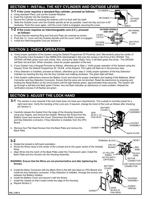
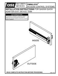
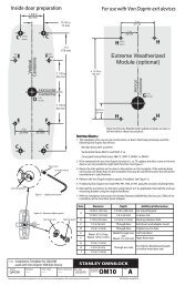
SECTION 1: INSTALL THE KEY CYLINDER AND OUTSIDE LEVERCYLINDER1-1 If the Lever requires a st<strong>and</strong>ard Key cylinder, proceed as follows:a. Using st<strong>and</strong>ard Pliers, pull out the Outside Retainer.b. Insert the Cylinder into the Outside Lever.RETAINERc. Secure the Cylinder by pressing the retainer until it is flush with the shelf.d. Slide the Outside Lever onto the Outside spindle as far as possible. Insert the Key <strong>and</strong> turn it 45°clockwise. Push the Lever again, until the Lever Catch is engaged, securing the Lever.1-2 If the Lever requires an Interchangeable core (I.C.), proceedas follows:a. Ensure that the retaining Ring <strong>and</strong> Anti-pick Plate are oriented as shown.b. Push the I.C. Lever onto the Outside Spindle until the Lever Catch is engaged.c. Install the Interchangeable Core per Section 8.SECTION 2: CHECK OPERATIONa. Verify proper operation of the System using the Default Programmer ID Proximity card. Momentarily place the center ofthe Proximity Card (Included in the OMNILOCK Administrator’s Kit) over the recess in the front of the OP2000. TheOP2000 will flash green once <strong>and</strong> unlock, then, during the Open Delay Time, it will flash green five times. The OP2000will flash red <strong>and</strong> lock. While unlocked, check for proper operation of the lock.b. If your System has a Keypad Proceed as follows, otherwise go to Step c: Verify proper operation of the System using theKeypad. Enter the Default Programmer ID, 1234, at the Keypad. The Lights will flash as in the previous step.c. If Key Detection is installed, proceed as follows, otherwise go to step d: Verify proper operation of the Key DetectionIndicator by inserting the Key into the Key Cylinder <strong>and</strong> rotating clockwise. The green light will flash.d. If the System malfunctions remove the Battery Cover <strong>and</strong> check for proper orientation <strong>and</strong> seating of the Batteries, MotorConnector <strong>and</strong> Key Detection Connector. Ensure that the wires are not pinched. Reset the electronics by pressing <strong>and</strong>holding the Reset Button on the circuit board until the light flashes green, approximately three seconds. The System willgo through a self-test <strong>and</strong> flash green 5 times. Any red flash indicates an electronics or motor problem. Repeat theverification process if all flashes are green.SECTION 3: ADJUST THE LOCK HAND3-1 This section is only required if the lock h<strong>and</strong> does not meet your requirements. The Lockset is normally preset for aright h<strong>and</strong> door. Verify the h<strong>and</strong>ing of the Lock <strong>and</strong>, if required, change the h<strong>and</strong> of the Lock as follows after checkingper Section 2.a. Carefully release the Gasket from the edge of the Housing Assemblyusing your fingers, <strong>and</strong> remove the Gasket. Remove the Screw from theBattery Cover <strong>and</strong> remove the Cover. Disconnect the Motor Connector<strong>and</strong> Key Detection connector, if Key Detection is installed, from the CPUBoard.b. Remove four Flat Head Screws from the Back Plate <strong>and</strong> remove theBack Plate.OUTSIDE SPINDLEEND VIEWLEVERCATCHOUTSIDESPINDLESEM#4-40 X .25PAN HEADGASKETBATTERYCOVERSHELFOUTSIDELEVERRETAININGRINGANTI-PICKPLATEHOUSINGASSEMBLYLOCKSETASSEMBLYBACK PLATE3-2a. Rotate the lockset to left-h<strong>and</strong> orientation.b. Route the Wires close to the center of the Lockset <strong>and</strong> to the upper center of the OutsideRose.c. Align Wires into the notch of the Back Plate under the Translucent Label. Install theBack Plate <strong>and</strong> four Screws into the Housing Assembly.WARNING: Ensure that the Wires are not pinched before <strong>and</strong> after tightening theScrews.d. Install the Motor Connector with the Black Wire to the left (see label on CPU Board) <strong>and</strong>install the Key Detection connector, if Key Detection is installed. Arrange the excess wirebetween the Battery Holders.e. Install the Battery Cover <strong>and</strong> secure it with the Screw.f. Install the Gasket so that it seats inside the edge of the Housing.g. Repeat Section 2.PG. 2 OF 4GASKETTERMINAL BLOCKCPU PCBOARD(2) YELLOWWIRESNO POLARITY(OPTIONAL)BATTERYCOVERSEMS#4-40X.25PAN HEADRESETBLACKWIREMOTORCONNECTORHOUSINGASSEMBLYSCREW(4REQD)REDWIREKEY DETECTIONCONNECTOR
Recensioni e segnalazioniUn altro membro della CasaSavoia che ben si dedicò ai problemidella Marina, fu Amedeo, primoDuca d’Aosta, che per due annifu anche Re di Spagna. Alla Marinavi arrivò tardi e su richiestadel ministro della Marina Ribotyche si ritrovò una forza armatacon personale demotivato e pochisoldi che non permettevano l’esecuzionené della giusta manutenzionené delle normali operazioni.Entusiasta e capace, il duca, nominatovice ammiraglio, s’interessòdella riorganizzazione dei sottufficialie dei marinai con delle propostetalmente all’avanguardia ... chesaranno realizzate trent’anni dopo.Nominato ispettore, si adoperò perrimettere in sesto le difese costiere esoprattutto per il completamentodella base navale di La Spezia.I Savoia, con l’unità dei territori,dovevano inevitabilmente far siche la nuova nazione s’impegnassesul mare per diventare una potenzadi pari dignità con le altre,per proteggere i propri commerci eper difendere un territorio conuno sviluppo costiero moltiplicatorispetto a quello del Regno Sardo-Piemontese (e, non ultimo, diventareuna potenza coloniale).La casa regnante, in effetti,non aveva gran potere sulle sceltepolitiche dei governi che si alternavano,ma sicuramente potevadare dei segnali; uno di questi fu ilcoinvolgimento diretto di membridi casa Savoia nella Regia Marina.L’Autore ci parla poi di Tommasoduca di Genova, che, entratoin Marina come cannoniere di 2 aclasse, preferì la carriera militarealla vita di corte. Fu abile com<strong>and</strong>antee qu<strong>and</strong>o rivestì incarichi dimaggior rilevanza, si rivelò un abileorganizzatore sfrutt<strong>and</strong>o le pocherisorse lesinate alla Marina pertenere al meglio le forze navali eapportare le migliorie necessarie.Infine, l’Autore si sofferma lungamentesugli ultimi, illustri, personaggidi casa Savoia che sonostati protagonisti delle vicendedella Forza Armata, e non solo,nella breve storia dell’Italia riunificata;si tratta di Luigi, duca degliAbruzzi, di Ferdin<strong>and</strong>o, principe diUdine, di Eugenio, duca d’Anconae di Aimone, duca d’Aosta.Il racconto storico, nel senso chela lettura scorre facilmente, pur essendoincentrato sui Savoia, è beninquadrato con le vicende europeedi sette secoli, con puntuali riferimenti.Ogni personaggio è ben descritto,tanto più quante numerosesono le fonti (davvero numerose) ein modo che il lettore si possa fareuna propria opinione senza essereinfluenzato dall’Autore.Quello che colpisce sono i collegamentifra i vari fatti storici, anchelontanissimi fra loro: rapidi, semplicie comprensibili anche ai “nonaddetti ai lavori”. <strong>Non</strong> mancanoparticolari riferimenti con l’attualitàal ripetersi di comportamenti erratioccorsi in epoche differenti (e cosìsi può amaramente constatare chela Storia, buona maestra, ha spesso,troppo spesso, cattivi scolari).Stéphan Jules BuchetGINO GALUPPINILa Forza Aereadella Regia MarinaUfficio Storico della MarinaMilitare - Roma 2010Pagg. 247 - Euro 35,00 (25,00al prezzo scontato a cui hannodiritto i soci della LNI)In questa Opera dedicata all’Aviazionedella Regia Marina,l’amm. Galuppini, autore assai notonell’ambiente della nostra Marina,recentemente scomparso, hascelto di rievocarne l’evoluzioneesclusivamente sotto l’aspetto ordinativoe normativo tralasci<strong>and</strong>oquello storico-operativo. Ne è nataun’Opera di consultazione che, purinteress<strong>and</strong>o presumibilmente unpubblico molto ridotto, risultafrutto di una meticolosa ricerca edi una rievocazione di strumentinormativi che hanno regolamentatotale specialità aviatoria in Italia,con brevi cenni a quanto contemporaneamenterealizzato all’estero.Infatti attraverso i numerosiprovvedimenti legislativi o soltantoamministrativi, scrupolosamentepassati in rassegna, l’Autore ricostruiscele realizzazioni aviatorieportate a termine dalle due ForzeArmate del regno, sia separatamente,sia in collaborazione.Laddove ritenuto opportuno,egli coglie anche l’occasione peranalizzare qua e là i profili dei piùillustri personaggi coinvolti, nonchéle caratteristiche tecniche didirigibili, aerei e idrovolanti adottatisia dal Regio Esercito, sia dallaRegia Marina fino alla costituzionedell’indipendente Regia Aeronauticanel 1923.Nel contesto dell’impostazioneprescelta dall’Autore, non può quindiche risultare privilegiata l’esposizionedelle norme che sovrinteserol’organica e la logistica della ForzaAerea in quel periodo, con sconfinamentinell’uniformologia e nei regolamentiretributivi e con riproduzionidei più rilevanti testi legislativi.L’Opera si conclude effettivamentenel 1925, anno in cui si realizzòun sereno trapasso di competenze,installazioni e materiali dallaForza Aerea della Regia Marinaal Commissariato dell’Aeronauticaed infine alla definitiva nuova costituendaForza Armata denominataRegia Aeronautica. <strong>Non</strong> mancatuttavia un sintetico e doverosoaccenno alla ricostruzione, sempresotto l’aspetto normativo, dell’Ispettoratodell’Aviazione della Marinanel 1950, dell’Aviazione Antisommergibilenel 1957 ed infinedell’Aviazione di Marina nel 1989.42novembre-dicembre 2010