INSIDE OUTSIDE - OSI Security Devices
INSIDE OUTSIDE - OSI Security Devices
INSIDE OUTSIDE - OSI Security Devices
- No tags were found...

Create successful ePaper yourself
Turn your PDF publications into a flip-book with our unique Google optimized e-Paper software.
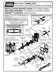
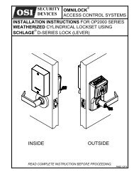
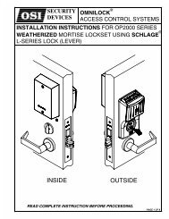
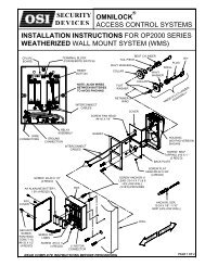
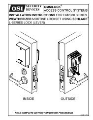
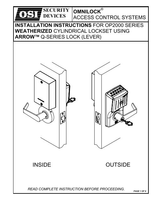
SECURITYDEVICESOMNILOCK ®ACCESS CONTROL SYSTEMSINSTALLATION INSTRUCTIONS FOR OP2000 SERIESWEATHERIZED CYLINDRICAL LOCKSET USINGARROW Q-SERIES LOCK (LEVER)<strong>INSIDE</strong><strong>OUTSIDE</strong>READ COMPLETE INSTRUCTION BEFORE PROCEEDING.PAGE 1 OF 8
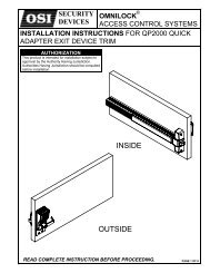
NOTE: A DOOR-CLOSER IS HIGHLY RECOMMENDEDFOR USE WITH THIS PRODUCT.THIS PRODUCT IS NORMALLY FACTORY-PACKEDFOR RIGHT-HAND 1-3/4” THICK DOORS.TO CHANGE HAND OF LOCK, SEEINSTRUCTION SECTION 3DO NOT USE ON DOORS THICKER THAN 1-3/4”RIGHT HAND SHOWNLEFTHANDDOOR HANDLINGRIGHTHANDI.C.<strong>OUTSIDE</strong>LEVERINTERCHANGEABLE CORE (I.C.)I.C. TAIL I.C. COREPIECE<strong>OUTSIDE</strong>LEVERCONTROLKEYKEYLEFT HANDREVERSEBEVEL<strong>OUTSIDE</strong><strong>INSIDE</strong><strong>OUTSIDE</strong>DOOR HAND DETERMINED FROM <strong>OUTSIDE</strong>RIGHT HANDREVERSEBEVELHOUSING ASSEMBLY(KEYPAD VERSION SHOWN)INTERCONNECTCABLESRETAINERCPU PCBOARDTERMINAL BLOCK(FOR REMOTE SWITCH)RESETBUTTONMOTORCONNECTOR<strong>OUTSIDE</strong> ROSEINSERT ASSEMBLYPLATEFLEXIBLEADAPTERCYLINDERPUSH PIN(PROVIDED)INTERCONNECTCABLESNUTROSEGASKETGROUNDCONNECTIONSSECURITYSCREWS, PAN HEAD,TORX T-15 #8-32 X 3/4"(2 REQ’D)SCREW #8 X 1/2"(4 REQ’D)AA ALKALINEBATTERY, 1.5V(4-REQD)SPINDLESCREW, #4-40 X 1/2"(2 REQ’D)LOCKBODYSEMS#4-40 X 1/4"PAN HEADGASKETCOVERGASKETBACKPLATEELECTRONICSHOUSING COVER<strong>INSIDE</strong>LEVERPAGE. 2 OF 8FLEXIBLEADAPTERSCREW, FLAT HEAD#10-32 X 2-1/4”(2-REQD)NUTROSESERIAL NO.LABELPLATE<strong>INSIDE</strong> ROSEINSERT ASSYSCREW, PAN HEAD#6 X 3/4“(2 REQ’D)LATCHUNITSCREWFLAT HEAD#8 X 3/4”(2 REQ’D) STRIKEFLAT HEAD, MACHINESCREW, #8-32 X 3/8” LG(4 REQ’D)SCREWFLAT HEAD#12 X 3/4”(2 REQ’D)STRIKEBOX
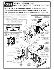
SECTION 1: INSTALL THE KEY CYLINDER AND <strong>OUTSIDE</strong> LEVER1-1 If the Lever requires a standard Key cylinder, proceed as follows:a. Using standard Pliers, pull out the Outside Retainer.b. Insert the Cylinder into the Outside Lever.c. Secure the Cylinder by pressing the retainer until it is flush with the shelf.d. Make certain that the Tab of the Flexible Adapter is located opposite to the Levercatch and projections of the Flexible Adapter line up with matching depressions ofthe Rose Insert Assembly.e. Slide the Outside Lever onto the Outside Spindle so that it engages with the key ofthe Flexible Adapter and press on it as far as possible. Insert the Key and turn it 45°clockwise. Push the Lever again, until the Lever Catch is engaged, securing theLever.1-2 If the Lever requires an Interchangeable Core (I.C.), proceedas follows:a. Ensure that the retaining Ring and Anti-pick Plate are oriented as shown.b. Push the I.C. Lever onto the Outside Spindle until the Lever Catch is engaged.c. Install the Interchangeable Core per Section 8.SECTION 2: CHECK OPERATIONa. Temporarily connect the Interconnect Cables to the connectors on the CPU Board and connectthe Ground Wire to the Lug on the CPU Bracket.b. Verify proper operation of the System using the Default Programmer ID Proximity card.Momentarily place the center of the Proximity Card (Included in the OMNILOCK Administrator’sKit) over the recess in the front of the OP2000. The OP2000 will flash green once and unlock,then, during the Open Delay Time, it will flash green five times. The OP2000 will flash red andlock. While unlocked, check for proper operation of the lock. If the System malfunctions, go toStep e.c. If your System has a Keypad proceed as follows: Verify proper operation of the System using theKeypad. Enter the Default Programmer ID, 1234, at the Keypad. The Lights will flash as in theprevious step. If the System malfunctions, go to Step e.d. Disconnect the Interconnect Cable Connectors and Ground Wire from the CPU PC Board.e. If the System malfunctions check for proper orientation and seating of the Batteries andInterconnect Cable Connectors on the CPU PC Board. Remove the Cover from the HousingAssembly and check for proper orientation and seating of the Motor Connector. Ensure that thewires are not pinched. Reset the electronics by pressing and holding the Reset Button on thecircuit board until the light flashes green, approximately three seconds. The System will gothrough a self-test and flash green 5 times. Any red flash indicates an electronics or motorproblem. Repeat the verification process if all flashes are green.SECTION 3: ADJUST THE LOCK HAND3-1 DISASSEMBLE THE HOUSING ASSEMBLYThis section is only required if the lock hand does notmeet your requirements. The Lockset is normallypreset for a right hand door. Verify the handing of theLock and, if required, change the hand of the Lock asfollows after checking per Section 2.a. Carefully remove the Gasket from the assembly.Remove the Screw from the Cover and remove theCover. Disconnect the Motor Connector from theInterconnect Board (see Step 3-2).b. Remove four Flat Head Screws from the Back Plateand remove the Back Plate.SEMS#4-40 X 1/4"PAN HEADLEVERCATCH<strong>OUTSIDE</strong>SPINDLECOVERCYLINDERRETAINER<strong>OUTSIDE</strong> SPINDLEEND VIEWHOUSINGASSEMBLYSHELF<strong>OUTSIDE</strong>LEVERRETAININGRINGANTI-PICKPLATEGASKETBACK PLATELOCKSETASSEMBLYPAGE 3 OF 8
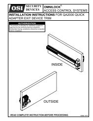
3-2 ADJUST THE LOCK HANDa. Rotate the lockset to left-hand orientation.b. Route the Wires close to the center of the Lockset and to theupper center of the Outside Rose.c. Align Wires into the notch of the Back Plate under theTranslucent Label. Install the Back Plate and four Screws intothe Housing Assembly.WARNING: Ensure that the Wires are not pinched before andafter tightening the Screws.SEMS#4-40X.25PAN HEADCOVERd. Install the Motor Connector with the Black Wire to the left (seelabel on CPU Board).e. Install the Cover and secure it with the Screw.f. Repeat Section 2.GASKETBLACK WIRESCREW(4 REQ’D)HOUSINGASSEMBLYINTERCONNECTINGCABLESRED WIREMOTORCONNECTORGROUND CONNECTIONSECTION 4: PREPARE THE DOOR4-1 MARK HOLE LOCATIONSa. Mark a height line on the door faces and edge(suggested height is 38” from the floor).b. Line up the Template at the correct marking forthe Door Bevel (high or low bevel, or flat).Position the centerline of the Template on theheight line. Note whether the holes should bemarked on the Inside, outside, or both sides ofthe door. Mark the Centers as required for theholes.TEMPLATEHIGHBEVELDOORDOORLOWBEVELc. Mark the center of the Door thickness on theheight line.4-2 DRILL HOLESa. Bore the 2-1/8” hole, the 3/4" and the two 7/16”holes half way through the door from both sidesto avoid splintering.b. Drill the four 1/8” dia. Holes only on the inside ofthe door.1” HOLE3/4” HOLE2-1/8” HOLEc. Add the notches to both sides of the door.d. Bore a 1” hole into the door edge center on theheight line, Use the Latch Unit Faceplate as apattern and mark the door edge. Mortise thedoor edge so that the front of the faceplate willbe flush with the door edge. Insert the LatchUnit into the 1” hole, making certain that theLatch Bolt Bevel faces the direction of theclosing Door.MOUNTINGSCREWSNOTCH(4 REQ’D)7/16” HOLE(2 REQ’D)e. Secure the Latch Unit with the Screws supplied.f. If a Remote Switch is to be used to operate theSystem, see Section 10.PAGE 4 OF 8LATCH UNIT<strong>OUTSIDE</strong>
SECTION 5: INSTALL THE SYSTEM ON THE DOOR5-1 VERIFY THE DOOR THICKNESS SETTINGNOTE: DO NOT USE ON A DOOR THICKER THAN 1-3/4” UNLESSTHE SYSTEM IS SPECIFICALLY DESIGNED FOR A THICKER DOOR.a. The Lockset is normally preset for a 1-3/4” Door. For 1-3/4”Door the “short mark” on the Lockset Plate is aligned withthe edge of the Lock Body.b. For a 1-3/4” door with a Push Plate (.050” max.) turn theNut counterclockwise until the short mark is the thicknessof the Push Plate from the edge of the Lock Body. Adjustthe Outside Nut with a pair of narrow jaw Pliers, a smallScrewdriver, a Scribe, or your Fingers.c. Install the Gasket so that it seats inside the edge of theHousing.GASKETLOCKBODYSHORT MARKLOCATEDON PLATENUT5-2 INSTALL THE HOUSING ASSEMBLYInstall the Housing Assembly on the outside of the door. Passthe Cables thru 3/4" hole in Door, ensure Cables are notpinched before proceeding. The Lock Body must engage theLatch Unit Prongs as shown. The Lock Body Retractor mustengage the Latch Unit Tail Piece.LOCKBODYLATCH UNITPRONGS5-3 SECURE THE HOUSING ASSEMBLY TOTHE DOORInstall the Plate and Nut on the inside, and secure thePlatewiththeScrews.INTERCONNECTCABLESGROUNDWIREPLATELOCK BODYRETRACTORLATCH UNITTAIL PIECESCREWSHEET METAL#6 X 3/4" (2 REQ’D) NUT5-4 INSTALL THE <strong>INSIDE</strong> LEVERa. Slide the Rose Insert onto the Spindle and secure the Rose Insert with theScrews.b. Slide the Flexible Adapter over the Spindle depressing the Lever Catch.Make certain that the Tab of the Flexible Adapter is located opposite to theLever Catch and projections of the Flexible Adapter line up with matchingdepressions of the Rose Insert Assembly.c. Place the Inside Rose onto the Rose Insert aligning the dimples with therecesses in the Rose Insert and turn clockwise to secure it.d. Slide the Inside Lever on the Inside Spindle so that it engages the Key ofthe Flexible Adapter and press it on as far as possible. Make certain thatthe Lever Catch on the Spindle is engaged with the Lever.SCREW FLAT HEAD,#10-32 X 2-1/4” (2 REQ’D)<strong>INSIDE</strong> ROSEINSERT ASSYINTERCONNECTCABLES<strong>INSIDE</strong>SPINDLEHOUSINGFLEXIBLE ADAPTER<strong>INSIDE</strong> LEVERROSEPAGE 5 OF 8
5-5 INSTALL THE CPU MODULEa. Pass the Interconnecting Cables through the hole in the CPU Module Bracket while aligning the Bracket with themounting holes in the Door. Secure the Bracket with the Screws.b. Connect Cables from the Housing Assembly to the bottom of the CPU PC board as shown (One 12 Pin and One 10 PinConnector). Connect the Ground Wire to the CPU Module Bracket.c. Connect the Ground Wire from the CPU Module Cover to the CPU Module Bracket. Install the Cover by placing theCover into position against the Door. Press the Cover against the Door and tighten the <strong>Security</strong> Screws until the Cover isseated. (Torx <strong>Security</strong> Wrench included)d. Repeat Step 2b, and if applicable, 2c to Verify proper operation.CAUTION: Binding or rough operation is an indication of improper installation.MOUNTINGPLATEINTERCONNECTINGCABLESSCREW#8-32 X 1/2 “4REQ’DGROUNDWIREGASKETGROUNDCONNECTIONS(SEE DETAIL “A”)SECURITYSCREWS, PAN HEAD,TORX T-15 #8-32 X3/4" (2 REQ’D)CPU MODULECOVERTERMINAL BLOCK(FOR REMOTE SWITCH)SEE SECTION 10RESETBUTTONHOUSING12 PINCONNECTORCIRCUIT BOARDCONNECTIONS(DETAIL “A”)GROUND WIREGREEN/YELLOW(4-INCHES)10 PINCONNECTORMODULE GROUNDCONNECTIONQUICK DISCONNECT,DOUBLE, MALE<strong>INSIDE</strong>LEVERPAGE 6 OF 8CPU COVER GROUNDCONNECTION
SECTION 6: INSTALL THE STRIKEa. Mark the Location of the Latch Bolt on the Door Frame.b. Center the Strike over the Latch Bolt Mark and, using the Strike as atemplate, mark the Frame.c. Using the Strike Box as a template, mark the Frame.d. Mortise the Frame to accept the Strike and Strike Box.e. Install the Strike Box and the Strike and secure with the Screws.SCREW#12 X 3/4"(2-REQD)STRIKE BOXSTRIKESECTION 7: PROGRAM THE SYSTEMIMPORTANT: To avoid unauthorized access, it is important to program a new Programmer ID.Refer to the OMNILOCK Administrator’s Guide for programming instructions. If the System has been installed on a door beforethe required programming information is available, and the system has a keypad the access Level may be set to Unlocked asfollows:a. Enter the Default Manager ID 2222, at the keypad, the green light will flash.b. Press 2, the green light will flash.c. Press and hold the CL key until the green light flashes four times. (The light will flash once when the CL keyispressed,continue to hold the key until the light flashes three more times.)d. The System will remain in the Unlocked mode.SECTION 8: INTERCHANGEABLE CORE8-1 INTERCHANGEABLE CORE (I.C.) AND TAIL PIECE MEMBERS INSTRUCTIONSBe certain to use the correct Tail Piece member with theCore. Six-Pin Cores use only the “L6” Tail Piece memberand Seven-Pin Cores use only the “L7” Tail Piece member.6-PINCORE7-PINCOREL6 TAIL PIECEMEMBER (6-PIN)L7 TAIL PIECEMEMBER (7-PIN)8-2 LEVER WITH INTERCHANGEABLE CORE (I.C.)a. Orient the Anti-Pick Plate as Shownb. Insert the I.C. Tail Piece into the I.C. Core. Insert the Control Key into the Core and turn it 15°clockwise. Insert the Core into the I.C. Outside Lever and turn the Control Key 15° counterclockwiseto lock the Core in the Lever.c. Remove the Control Key.ANTI-PICK PLATERETAININGRINGPAGE. 7 OF 8
OMNI LOCKSECTION 9: REMOVAL OF LEVER9-1 REMOVING <strong>OUTSIDE</strong> LEVER WITH STANDARD CYLINDERa. Insert the Key into the Cylinder and turn 45° clockwise.b. Depress the Lever Catch through the hole in the OutsideLever by using the Push Pin provided or another suitabletool.c. Slide the Outside Lever from the Spindle.KEY<strong>OUTSIDE</strong>LEVERPUSH PIN(PROVIDED)9-2 REMOVING <strong>OUTSIDE</strong> LEVER WITH INTERCHANGEABLE CORE (I.C.)a. Insert the control Key into the Core and rotate it 15° clockwise.Pull on the Key to remove the Core. Be sure that the I.C. TailPiece is removed with the Core.b. Ensure that the Retaining Ring and the Anti-Pick Plate are alignedwith the Lever Catch as shown.c. Insert an awl or a small screwdriver through the I.C. Outside Leverand into the slot in the Anti-Pick Plate. Depress the Lever Catchtoward the Door Hinge and slide the I.C. Outside Lever from theSpindle.LEVER<strong>OUTSIDE</strong>SPINDLE<strong>OUTSIDE</strong> SPINDLEEND VIEWRETAININGRINGANTI-PICKPLATE9-3 REMOVING THE <strong>INSIDE</strong> LEVERa. Depress the Lever Catch through the hole in the Inside Lever by using the PushPin provided or another suitable tool.b. Slide the Inside Lever from the Spindle.<strong>INSIDE</strong>LEVERPUSH PIN (PROVIDED)SECTION 10: REMOTE SWITCHa. Remote operation of the System may be accomplishedby a momentary Switch closure. This may be desirablefor someone monitoring a protected entrance, such asa receptionist. Momentarily pressing the Switch willcause the System to go through a normal unlock andlock sequence. If the Switch is held closed, the opentime will be extended.b. Connect a twisted pair of wires from the Terminal Blockon the CPU PC Board to a normally open momentarycontact Switch. Plan the route for your wire and theaccess route through the door to the PC Board on theinside of the door.TO CPU MODULE<strong>INSIDE</strong>SWITCHTWISTEDPAIRCopyright 2002 <strong>OSI</strong> <strong>Security</strong> <strong>Devices</strong> Inc. All Rights Reserved.OMNILOCK is a Registered Trademark of <strong>OSI</strong> <strong>Security</strong> <strong>Devices</strong> Inc. ARROW is a Trademark of Arrow Lock Co.SECURITYDEVICES(Website: WWW.OMNILOCK.COM)PAGE 8 OF 811568 REV A1580 JAYKEN WAYCHULA VISTA, CALIFORNIA. 91911(619) 628-1000 FAX (619) 628-1001