schlage - OSI Security Devices
schlage - OSI Security Devices
schlage - OSI Security Devices
- No tags were found...

Create successful ePaper yourself
Turn your PDF publications into a flip-book with our unique Google optimized e-Paper software.
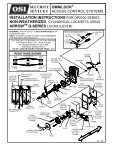
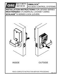
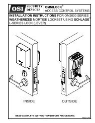
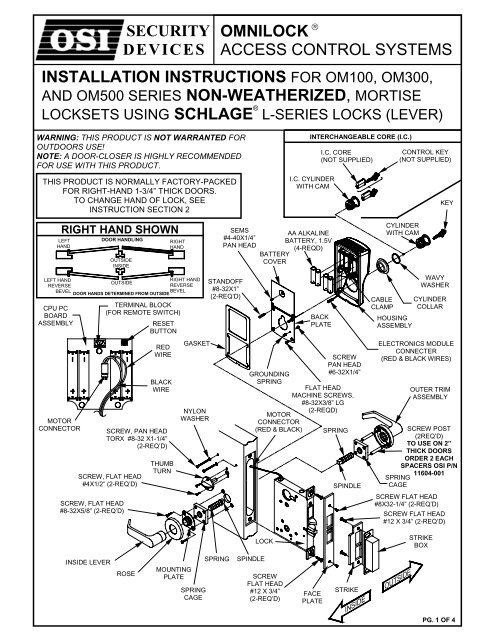
SECURITYDEVICESOMNILOCK ®ACCESS CONTROL SYSTEMSINSTALLATION INSTRUCTIONS FOR OM100, OM300,AND OM500 SERIES NON-WEATHERIZED, MORTISELOCKSETS USING SCHLAGE ® L-SERIES LOCKS (LEVER)WARNING: THIS PRODUCT IS NOT WARRANTED FOROUTDOORS USE!NOTE: A DOOR-CLOSER IS HIGHLY RECOMMENDEDFOR USE WITH THIS PRODUCT.INTERCHANGEABLE CORE (I.C.)I.C. CORE(NOT SUPPLIED)CONTROL KEY(NOT SUPPLIED)THIS PRODUCT IS NORMALLY FACTORY-PACKEDFOR RIGHT-HAND 1-3/4” THICK DOORS.TO CHANGE HAND OF LOCK, SEEINSTRUCTION SECTION 2I.C. CYLINDERWITH CAMKEYRIGHT HAND SHOWNLEFTHANDDOOR HANDLINGOUTSIDEINSIDERIGHTHANDSEMS#4-40X1/4”PAN HEADAA ALKALINEBATTERY, 1.5V(4-REQD)BATTERYCOVERCYLINDERWITH CAMLEFT HANDREVERSEBEVELCPU PCBOARDASSEMBLYMOTORCONNECTOROUTSIDEDOOR HANDS DETERMINED FROM OUTSIDETERMINAL BLOCK(FOR REMOTE SWITCH)RESETBUTTONSCREW, FLAT HEAD#4X1/2” (2-REQ’D)SCREW, FLAT HEAD#8-32X5/8” (2-REQ’D)REDWIREBLACKWIRESCREW, PAN HEADTORX #8-32 X1-1/4”(2-REQ’D)THUMBTURNRIGHT HANDREVERSEBEVELGASKETNYLONWASHERSTANDOFF#8-32X1”(2-REQ’D)GROUNDINGSPRINGMOTORCONNECTOR(RED & BLACK)LOCKBACKPLATESCREWPAN HEAD#6-32X1/4”FLAT HEADMACHINE SCREWS,#8-32X3/8” LG(2-REQD)SPRINGSPINDLECABLECLAMPHOUSINGASSEMBLYWAVYWASHERCYLINDERCOLLARELECTRONICS MODULECONNECTER(RED & BLACK WIRES)OUTER TRIMASSEMBLYSCREW POST(2REQ’D)TO USE ON 2”THICK DOORSORDER 2 EACHSPACERS <strong>OSI</strong> P/N11604-001SPRINGCAGESCREW FLAT HEAD#8X32-1/4” (2-REQ’D)SCREW FLAT HEAD#12 X 3/4” (2-REQ’D)STRIKEBOXINSIDE LEVERROSEMOUNTINGPLATESPRINGCAGESPRINGSPINDLESCREWFLAT HEAD#12 X 3/4”(2-REQ’D)FACEPLATESTRIKEPG. 1 OF 4
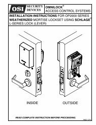
SECTION 1: CHECK OPERATIONa. Connect the Lock Connector to the Electronics Module Connector so that the Red Wires are aligned.b. Verify proper operation of the System by entering the Default Master Code 5011234. The Systemwill flash three times to indicate the Battery level and unlock. It will remain unlocked for approximately5 seconds before flashing red and relocking. While unlocked, check for proper operation of the Lockusing the Outer Trim Assembly and Spindle.c. Verify communication with the WP4000 Printer.1. Turn on the Printer and Position it over the Keypad so that the Infrared Port of the Printer is alignedover the Infrared Port of the System.2. Enter the Default Master Code 5011234 at the Keyboard and then enter 99.3. The Printer will print some System data and then present a menu of choices.4. Enter 0 (END) at the Keypad. The System will flash red and re-locked.5. If the system malfunctions, remove the Battery Cover and check for proper orientation and seatingof the Batteries and Motor Connector. Also ensure that the wires are not pinched. Reset theelectronics by pressing and holding the Reset Button on the circuit board until the light on theKeypad flashes green, approximately three to five seconds. The System will go through a self-testand flash green 5 times. Any red flash indicates an electronics or motor problem. If all flashes aregreen, repeat Steps b and c.d. Disconnect the Lock Connector.SECTION 2: ADJUST THE LOCK HANDThis section is only required if the lock hand, as received, doesnot meet your requirements. The Lock Chassis is normallypreset for a Right Hand Door. Verify the handing of the Lockand, if required, change the hand of the Lock as follows afterchecking per Section 1.a. Pull the Anti-Friction Tongue and Latch Bolt away from theChassis and rotate the complete unit 180 degrees to adjustfor the Door Handing.b. Remove the Catch Screw from one side of the Chassis andinstall on the opposite side (Catch Screw must always beon the inside side of the Chassis for proper functioning ofthe Lock).SECTION 3: PREPARE THE DOORCATCH SCREW(Locate on inside side of Chassis)LH/LHRANTI-FRICTIONTONGUE ANDLATCHBOLT(Pull and Rotate 180°)RH/RHR3-1 MARK THE HEIGHT LINEa. Mark a Height line on the Door Facesand Edge (suggested height is 38"from the floor).NOTE: If the Frame has already beenprepared for an Schlage Strike, measure2-3/32" down from the center of the Striketo locate the centerline of the Lever.3-2 MARK THE DOOR SURFACE AND THE STRIKE P<strong>OSI</strong>TIONa. Detach the Door Edge portion ofthe Template from the DoorSurface portion of the Template.b. Line up the Door Surfaceportion of the Template at thecorrect marking for the DoorBevel (high or low bevel; or flat).c. Position the Lever Centerline ofthe Template on the Height linedrawn on the Door.d. Spot only those holes requiredfor the Lockset being installed.e. Mark the Centerline of the Strikeposition on the Frame.f. Spot both sides of the Door.CAUTION: Read the Templatethoroughly, and spot onlythose holes required for eachside of the Door.DOORSURFACEPORTION OFTEMPLATE3-3 MARK THE DOOR EDGEa. Center the Door Edge portion of the Template on the Door Edgeand align the Lever Centerline of the Template on the height linedrawn on the Door.b. Spot the top and bottom points of the Lock Case Mortise andmark the Face Plate top reference as illustrated below.PG. 2 OF 4MARK FACEPLATE TOPREFERENCEDOOR EDGEPORTION OFTEMPLATE
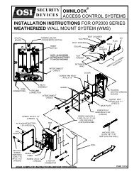
3-4 MORTISE THE DOOR EDGEa. Mortise the Door Edge for the Lock Caseto the dimensions shown on the Template.b. Insert the Lock (with the Face Plate attached)into the Mortise.CAUTION: Do not pinch the Motor Wires.c. Center the Face Plate (Lock attached) on theDoor Edge and align the top of the Face Platewith the reference mark. Scribe the Face Plateoutline as illustrated. Remove the lock fromthe door.d. Mortise the Door Edge to the Lock Face thickness.ALIGN WITHREFERENCEMARKMORTISE TODIMENSIONS OFTHE LOCK FACE7/32”3-5 DRILL THE DOOR SURFACE HOLESDrill the required holes through the outside and inside of the Door.CAUTION: Drill the holes only halfway through the Door from each side.SECTION 4: INSTALL THE HOUSING / LOCK ASSEMBLY4-1a. Remove the Armor Front and guide the Lock Connector and the Lock into theMortise so that the Cable passes through the slot above the Cylinder Hole andthe Lock is seated in the Mortise.CAUTION: Do not pinch the Cable.b. Spot the hole location for the Case Attachment Screws and removethe Lock from the Mortise. For Wood Doors, drill 1/8" dia. pilot holesfor the Case Attachment Screws, and counter drill the holes 7/32" dia.x 3/16" deep for Combination Screws. For Metal Doors, drill 3/16” dia. holes.CASEATTACHMENTSCREWSLOCKLOCKCONNECTOR4-2 ATTACH THE TRIMa. Insert the Inside and Outside Spindles and Springs so that the Shoulder ofthe Spindle is in contact with the Hub of the Lock case.b. Thread the Screw Posts into the Outside Rose.c. Place the Spring Cage onto the Screw Posts with the arrows on the SpringCage pointing in the direction of the Lever rotation.d. Install the Outside Trim onto the Outside Spindle with the Screw Posts thruthe holes in the Lock Case.e. Slide the Inside Spring Cage over the Inside Spindle and Screw Posts(Arrows on the Spring Cage pointing in the direction of the Lever rotation).f. Place the Mounting Plate over the Inside Spindle. Align the Screw Holeswith the Screw Posts.g. Insert and tighten the Mounting Screws.h. Place the Inside Rose over the Mounting Plate. Slide the Lever intoposition and tighten the Lever Bushing with the Spanner Wrench.i. If required, install the Turn Piece and project the Deadbolt. Align the ScrewHoles vertically and fasten with the Screws.SPRINGCAGEMOUNTINGPLATESPANNERTURNPIECEMOUNTINGSCREWINSIDELEVERINSIDEROSESPINDLEANDSPRINGOUTSIDETRIMSCREWPOSTDEADBOLTPROJECTED4-3 INSTALL THE ELECTRONIC MODULEa. Guide the Module Connector through the hole in the Module.b. Guide the Lock Connector through the hole in the Module andplace the Module against the Door so that the Standoffs andGrounding Spring enter their respective holes.c. Install the Mounting Screws and Washers finger tight.d. Connect the Lock Connector to the Module Connector so thatthe Wire colors match.e. Insert the Cables and the Connectors into the Module so thatthey are clear of the Cylinder Hole.MOUNTINGSCREWWASHERLOCKCONNECTORMODULECONNECTORPG. 3 OF 4
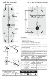
OMNILOCK4-4 INSTALL THE CYLINDERa. Insert the Cylinder with the Wavy Washer and Collar into theModule and partially screw it into the lock.b. Vertically align the Module and tighten the Module MountingScrews. Then tighten the Cylinder until it is snug with the keyway atthe bottom.c. Tighten the Cylinder Retaining Screw and install the Armor Front.d. Repeat Section 1b & 1c to verify operation.CYLINDERRETAININGSCREWACCESSSECTION 5: INSTALL THE STRIKEa. Draw a vertical line on the Door Frame 1/2 the Door thickness from the Door Stop.b. Mortise the Door Frame for the Strike Box to the dimensions shown on the Template.c. Align the Strike Template on the frame with the vertical line and the Strike centerlinemark on the frame from Section 3-2e and spot for the mortise holes and the strikerecess.CAUTION: Allow for paint buildup or weather stripping if required.d. Recess 5/32" for flush fit of the Strike and the Strike Box. (Additional recess isrequired when using strike reinforcement.)e. Drill the required mounting holes.NOTE: For wood doors, drill 1/8" dia. pilot holes and counter drill the holes 7/32" dia. x3/16" deep for Combination Screws. For metal doors, drill 3/16" dia. holes.f. Install the Strike Box and the Strike and secure with the Screws.CAUTION: Be sure auxiliary latch does not enter strike opening.SECTION 6: PROGRAM THE LOCKIMPORTANT: To avoid unauthorized access, it is important to program a new Master Code.For Programming instructions refer to the Quick Reference Guide shipped with this product or to the OMNILOCK UserGuide which may be ordered by calling Customer Service at 619-628-1000 or it may be downloaded from our websitehttp://www.omnilock.com/files/om135man.pdfSECTION 7: REMOTE SWITCHa. Remote operation of the System may be accomplished by a momentary Switchclosure. This may be desirable for someone monitoring a protected entrance, such as areceptionist. Momentarily pressing the Switch will cause the System to go through anormal unlock and lock sequence. If the Switch is held closed, the open time will beextended.b. Connect a twisted pair of wires from the Terminal Block on the PC Board to a normallyopen momentary contact Switch. Plan the route for your wire and the access routethrough the door to the PC Board in the OMNILOCK Module. Plan for disconnectingthe wires in the Module area so that the System can be removed from the door tochange the Batteries as required.SWITCHTWISTEDPAIRINSTALLER NOTES:Leave these instructions and other documents with the User.Copyright ©2001 <strong>OSI</strong> <strong>Security</strong> <strong>Devices</strong> Inc. All Rights ReservedOMNILOCK is a Registered Trademark of <strong>OSI</strong> <strong>Security</strong> <strong>Devices</strong> Inc. SCHLAGE is a register trademark of Schlage Lock Co. 11521 Rev ASECURITYDEVICES(Website: WWW.OMNILOCK.COM)PG. 4 OF 41580 JAYKEN WAYCHULA VISTA, CALIFORNIA. 91911(619) 628-1000 FAX (619) 628-1001