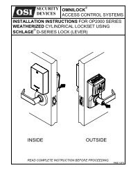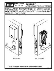
schlage - OSI Security Devices
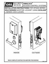
schlage - OSI Security Devices
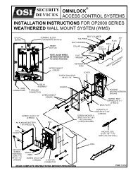
schlage - OSI Security Devices
- No tags were found...

Create successful ePaper yourself
Turn your PDF publications into a flip-book with our unique Google optimized e-Paper software.
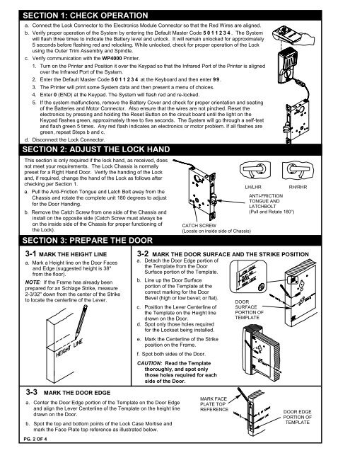
SECTION 1: CHECK OPERATIONa. Connect the Lock Connector to the Electronics Module Connector so that the Red Wires are aligned.b. Verify proper operation of the System by entering the Default Master Code 5011234. The Systemwill flash three times to indicate the Battery level and unlock. It will remain unlocked for approximately5 seconds before flashing red and relocking. While unlocked, check for proper operation of the Lockusing the Outer Trim Assembly and Spindle.c. Verify communication with the WP4000 Printer.1. Turn on the Printer and Position it over the Keypad so that the Infrared Port of the Printer is alignedover the Infrared Port of the System.2. Enter the Default Master Code 5011234 at the Keyboard and then enter 99.3. The Printer will print some System data and then present a menu of choices.4. Enter 0 (END) at the Keypad. The System will flash red and re-locked.5. If the system malfunctions, remove the Battery Cover and check for proper orientation and seatingof the Batteries and Motor Connector. Also ensure that the wires are not pinched. Reset theelectronics by pressing and holding the Reset Button on the circuit board until the light on theKeypad flashes green, approximately three to five seconds. The System will go through a self-testand flash green 5 times. Any red flash indicates an electronics or motor problem. If all flashes aregreen, repeat Steps b and c.d. Disconnect the Lock Connector.SECTION 2: ADJUST THE LOCK HANDThis section is only required if the lock hand, as received, doesnot meet your requirements. The Lock Chassis is normallypreset for a Right Hand Door. Verify the handing of the Lockand, if required, change the hand of the Lock as follows afterchecking per Section 1.a. Pull the Anti-Friction Tongue and Latch Bolt away from theChassis and rotate the complete unit 180 degrees to adjustfor the Door Handing.b. Remove the Catch Screw from one side of the Chassis andinstall on the opposite side (Catch Screw must always beon the inside side of the Chassis for proper functioning ofthe Lock).SECTION 3: PREPARE THE DOORCATCH SCREW(Locate on inside side of Chassis)LH/LHRANTI-FRICTIONTONGUE ANDLATCHBOLT(Pull and Rotate 180°)RH/RHR3-1 MARK THE HEIGHT LINEa. Mark a Height line on the Door Facesand Edge (suggested height is 38"from the floor).NOTE: If the Frame has already beenprepared for an Schlage Strike, measure2-3/32" down from the center of the Striketo locate the centerline of the Lever.3-2 MARK THE DOOR SURFACE AND THE STRIKE P<strong>OSI</strong>TIONa. Detach the Door Edge portion ofthe Template from the DoorSurface portion of the Template.b. Line up the Door Surfaceportion of the Template at thecorrect marking for the DoorBevel (high or low bevel; or flat).c. Position the Lever Centerline ofthe Template on the Height linedrawn on the Door.d. Spot only those holes requiredfor the Lockset being installed.e. Mark the Centerline of the Strikeposition on the Frame.f. Spot both sides of the Door.CAUTION: Read the Templatethoroughly, and spot onlythose holes required for eachside of the Door.DOORSURFACEPORTION OFTEMPLATE3-3 MARK THE DOOR EDGEa. Center the Door Edge portion of the Template on the Door Edgeand align the Lever Centerline of the Template on the height linedrawn on the Door.b. Spot the top and bottom points of the Lock Case Mortise andmark the Face Plate top reference as illustrated below.PG. 2 OF 4MARK FACEPLATE TOPREFERENCEDOOR EDGEPORTION OFTEMPLATE