specifica prodotto istruzioni per l'uso e la manutenzione - Beta
specifica prodotto istruzioni per l'uso e la manutenzione - Beta
specifica prodotto istruzioni per l'uso e la manutenzione - Beta

Create successful ePaper yourself
Turn your PDF publications into a flip-book with our unique Google optimized e-Paper software.
• Esame accurato: esame visivo effettuato da una <strong>per</strong>sona competente e, se necessario, coadiuvato daaltri mezzi, quali i controlli non-distruttivi, al fine di individuare danneggiamenti o usure che possonoalterare l’utilizzo dell’articolo.• Persona competente: <strong>per</strong>sona designata, istruita correttamente, qualificata <strong>per</strong> conoscenza edes<strong>per</strong>ienza pratica, che ha ricevuto le <strong>istruzioni</strong> necessarie <strong>per</strong> eseguire le prove e gli esami richiesti.ATTENZIONE: il coefficiente di sicurezza è soltanto un’indicazione <strong>per</strong> <strong>la</strong> sicurezza del <strong>prodotto</strong>.Non si devono mai su<strong>per</strong>are le forze (WFL) indicate nel<strong>la</strong> tabel<strong>la</strong>.2) SPECIFICHE DI COLLAUDOL’articolo è sottoposto a una serie di severi controlli <strong>per</strong> accertarne <strong>la</strong> funzionalità prestazionale e <strong>la</strong>rispondenza alle specifiche.La numerosità del campione e i re<strong>la</strong>tivi piani di campionamento sono scelti in funzione del<strong>la</strong> caratteristicada verificare in accordo e <strong>per</strong> quanto previsto dal<strong>la</strong> norma UNI ISO 2859/1, e i risultati archiviatinell’ufficio qualità dello stabilimento di Sulmona.2.A Controllo dimensionaleVerifica che le dimensioni dell’articolo rientrino nelle tolleranze stabilite dai re<strong>la</strong>tividisegni di costruzione interni.2.B Controllo visivoVerifica <strong>la</strong> presenza di eventuali im<strong>per</strong>fezioni dovute a stampaggio, <strong>la</strong>vorazionemeccanica, rivestimento su<strong>per</strong>ficiale e rispondenza del<strong>la</strong> marcatura a disegni di faseinterni.2.C Analisi chimicaVerifica <strong>la</strong> rispondenza del<strong>la</strong> composizione chimica del materiale, entro i limiti stabilitidalle re<strong>la</strong>tive norme.2.D Prove di trazioneVerifica che l’accessorio sottoposto a una trazione arrivi a rottura, dopo che <strong>la</strong> forzaapplicata abbia almeno su<strong>per</strong>ato il carico di <strong>la</strong>voro moltiplicato <strong>per</strong> il coefficiente disicurezza.La prova è eseguita in accordo con <strong>la</strong> norma UNI 10002/1.Divisione del<strong>la</strong> BETA UTENSILI SPA, Via Volta, 18 - 20845 SOVICO (MB) ITALY Tel. +39.039.20771-Fax + 39.039.2010742
3) COME LEGGERE LA MARCATURASull’accessorio sono stampate in maniera indelebile sigle come sotto riportato:1) Marchio produttore (R-ROBUR)4) AVVERTENZE GENERALICon riferimento a quanto riportato in queste <strong>istruzioni</strong> d’uso, <strong>la</strong> BETA UTENSILI SPA declina ogniresponsabilità in caso di:• uso degli accessori contrario alle leggi nazionali sul<strong>la</strong> sicurezza e sull’antinfortunistica;• errata scelta o predisposizione dell’apparecchio con il quale saranno connessi;• mancata o errata osservanza delle <strong>istruzioni</strong> <strong>per</strong> l’uso;• modifiche agli accessori;• uso improprio e omessa <strong>manutenzione</strong> ordinaria;• uso combinato ad accessori non conformi.!ATTENZIONE: I dati di marcatura non devono essere rimossi con mo<strong>la</strong>ture o abrasioni (neancheaccidentali; gli articoli senza riferimenti di identificazione devono essere resi inutilizzabili erottamati).Non è consentito apporre caratteri aggiuntivi a quelli di fabbricazione.Divisione del<strong>la</strong> BETA UTENSILI SPA, Via Volta, 18 - 20845 SOVICO (MB) ITALY Tel. +39.039.20771-Fax + 39.039.2010742
5) CRITERI DI SCELTAI parametri che devono essere attentamente considerati nel<strong>la</strong> scelta dell’anello sono:5.A FORZA LIMITE DI LAVOROLa trazione esercitata sull’anello deve essere inferiore o uguale al valore del<strong>la</strong> forza limite di <strong>la</strong>voro(WFL) previsto <strong>per</strong> l’articolo preso in considerazione, e riportato nel<strong>la</strong> tabel<strong>la</strong> “A”.5.B ELEMENTO DI ACCOPPIAMENTOAssicurarsi che l’elemento di collegamento sia adeguato alle caratteristiche di portata dell’anello.La fune o qualsiasi altro componente utilizzato deve essere di dimensioni adeguate come da tabel<strong>la</strong> “A”,evitando così fenomeni di intaglio.5.C TEMPERATURE D’IMPIEGOLa tem<strong>per</strong>atura d’impiego consentita dovrà essere compresa tra –20 °C e +80 °C.Al di fuori di questi valori non è più garantita <strong>la</strong> forza limite di <strong>la</strong>voro.5.D VITA E FREQUENZA DI UTILIZZOL’accessorio <strong>la</strong>vora in <strong>per</strong>fetta efficienza fin quando restano invariate le sue caratteristiche geometriche efisiche.Sostituire quindi l’anello quando si notano riduzioni di sezione, deformazioni, corrosioni o instabilità diaccoppiamento.6) CONDIZIONI NON AMMESSENon è consentito far <strong>la</strong>vorare gli anelli nei seguenti casi:• quando <strong>la</strong> forza applicata è su<strong>per</strong>iore al “WFL” consentito;• nelle condizioni in cui si possono creare delle sollecitazioni di tipo dinamico o carichipulsanti;• far <strong>la</strong>vorare gli anelli a tem<strong>per</strong>ature diverse da quelle consentite;• quando <strong>la</strong> direttrice delle forze non si sviluppa lungo l’asse principale.7) CONTROLLI PRELIMINARIPrima del<strong>la</strong> messa in servizio e/o del montaggio gli accessori devono essere control<strong>la</strong>ti da una <strong>per</strong>sonacompetente adeguatamente addestrata.• Control<strong>la</strong>re l’integrità dell’anello e in partico<strong>la</strong>re che non vi siano tagli, piegature,incisioni, abrasioni, incrinature o cricche, filetti irrego<strong>la</strong>ri, corrosioni, bave taglienti,usure provocate dall’utilizzo o difetti dovuti a cattivo stoccaggio.• Rilevare e registrare le dimensioni con riferimento al<strong>la</strong> tabel<strong>la</strong> “A”.• Control<strong>la</strong>re l’integrità del<strong>la</strong> marcatura.• Verificare <strong>la</strong> bontà dell’accoppiamento tra i filetti.Divisione del<strong>la</strong> BETA UTENSILI SPA, Via Volta, 18 - 20845 SOVICO (MB) ITALY Tel. +39.039.20771-Fax + 39.039.2010742
8) INSTALLAZIONE - ISTRUZIONI PER IL MONTAGGIOAvvitare gli anelli sul<strong>la</strong> canau<strong>la</strong> in maniera da ottenere l’a<strong>per</strong>tura massima e collegarli agli elementi damettere in trazione.Inserire solo una fune o un solo elemento <strong>per</strong> ogni terminale.Esercitare <strong>la</strong> trazione agendo sul corpo centrale, facendo attenzione che, una volta raggiunta <strong>la</strong> condizionedi <strong>la</strong>voro, gli anelli siano inseriti nel corpo <strong>per</strong> almeno tutta <strong>la</strong> lunghezza del filetto di quest’ultimo.Nell’esercitare <strong>la</strong> trazione assicurarsi che il tenditore abbia piena libertà di movimento e diautoposizionamento; non devono quindi mai presentarsi forzature o interferenze che possano generarecomponenti di forza <strong>la</strong>terali.La condizione del<strong>la</strong> trazione deve essere control<strong>la</strong>ta dopo breve tempo <strong>per</strong> compensare eventualiadattamenti del sistema.Partico<strong>la</strong>re attenzione deve essere posta durante il tensionamento affinché non venga su<strong>per</strong>ata <strong>la</strong> forzalimite di <strong>la</strong>voro (WFL, vedi tabel<strong>la</strong> ”A”), <strong>per</strong> non incorrere in deformazioni <strong>per</strong>manenti, soprattutto nelcaso si usino leve o mezzi meccanici.9) USO DELL’ACCESSORIO - PRESA E MANOVRAL’anello è stato concepito <strong>per</strong> essere utilizzato in situazioni statiche. Control<strong>la</strong>re <strong>per</strong>iodicamente lecondizioni del<strong>la</strong> trazione, lo stato di conservazione degli elementi e il loro accoppiamento, in riferimentoal<strong>la</strong> tabel<strong>la</strong> “Interventi di <strong>manutenzione</strong> e controllo”.10) CONTROINDICAZIONI D’USOL’utilizzo dell’accessorio <strong>per</strong> scopi non previsti, il suo uso in condizioni estremamente <strong>per</strong>icolose e <strong>la</strong>carenza di <strong>manutenzione</strong> possono comportare gravi situazioni di <strong>per</strong>icolo <strong>per</strong> l’incolumità delle<strong>per</strong>sone esposte e di danno <strong>per</strong> l’ambiente di <strong>la</strong>voro, oltre che pregiudicare <strong>la</strong> funzionalità e <strong>la</strong> sicurezzaeffettiva del <strong>prodotto</strong>. Le azioni di seguito citate, che, ovviamente, non possono coprire l’intero arco dipotenziali possibilità di “cattivo uso” dell’accessorio, costituiscono tuttavia quelle “ragionevolmente” piùprevedibili. Quindi:• NON utilizzare l’accessorio collegandolo ad apparecchiature di dimensioni, tem<strong>per</strong>atura,punto d’aggancio e forma non idonei alle sue caratteristiche;• NON utilizzare l’accessorio <strong>per</strong> il sollevamento;• NON mettere in tensione apparecchiature che possono cambiare <strong>la</strong> loro configurazionestatica, il loro baricentro o lo stato chimico-fisico;• NON utilizzare l’accessorio in apparecchiature destinate al trasporto di <strong>per</strong>sone o animali;• NON usare l’accessorio <strong>per</strong> trainare carichi vinco<strong>la</strong>ti;• NON o<strong>per</strong>are in aree dove è prescritto l’uso di componenti antidef<strong>la</strong>granti/antiscintil<strong>la</strong> o inpresenza di forti campi magnetici;• NON saldare sull’accessorio partico<strong>la</strong>ri metallici, né intervenire con riporti di saldatura outilizzarlo come massa <strong>per</strong> saldatrici.11) IDONEITÀ ALL’UTILIZZOL’accessorio è stato sottoposto a col<strong>la</strong>udo presso il costruttore <strong>per</strong> accertare <strong>la</strong> rispondenza funzionale eprestazionale dello stesso. L’attestato che accompagna <strong>la</strong> fornitura certifica il su<strong>per</strong>amento con esitopositivo dei test di col<strong>la</strong>udo. L’utilizzatore deve eseguire in ogni caso, prima di iniziare a o<strong>per</strong>are, <strong>la</strong>verifica del<strong>la</strong> rispondenza funzionale e prestazionale dell’accessorio instal<strong>la</strong>to <strong>per</strong> confermare l’idoneitàall’impiego dell’intera instal<strong>la</strong>zione.Divisione del<strong>la</strong> BETA UTENSILI SPA, Via Volta, 18 - 20845 SOVICO (MB) ITALY Tel. +39.039.20771-Fax + 39.039.2010742
12) ISPEZIONE E MANUTENZIONEComprende una serie di o<strong>per</strong>azioni eseguite da <strong>per</strong>sonale competente istruito allo scopo, re<strong>la</strong>tive acontrolli ed esami accurati durante l’impiego.Di seguito l’elenco dei controlli da effettuare con cadenze indicate nel<strong>la</strong> tabel<strong>la</strong> “Interventi di<strong>manutenzione</strong> e controllo”.• VISIVO: verificare l’assenza di difetti su<strong>per</strong>ficiali, quali cricche, incisioni, tagli o fessure,abrasioni.• CONDIZIONI DEL FILETTO: esaminare lo stato del filetto, che non deve presentare usure,deformazioni e ammaccature, e l’accoppiamento deve essere preciso, stabile e senzaeccessivo gioco.• DEFORMAZIONE: verificare che l’accessorio non sia deformato, misurando con un calibrole dimensioni critiche, come indicato nel<strong>la</strong> tabel<strong>la</strong> “A”. NON sono tollerate deformazionirispetto alle quote rilevate al<strong>la</strong> prima messa in servizio.• USURA: verificare che i punti di contatto non siano usurati, misurando con un calibro ledimensioni critiche indicate nel<strong>la</strong> tabel<strong>la</strong> “A”.• STATO DI CONSERVAZIONE: verificare l’assenza di ossidazione e corrosione,soprattutto in caso di utilizzo all’a<strong>per</strong>to; verificare l’assenza di cricche con metodi idonei (p.es. liquidi penetranti).Le registrazioni di questi controlli devono essere conservate.Tabel<strong>la</strong> interventi di <strong>manutenzione</strong> e controlloTipo di controlloControllo visivo gener.Condizioni del filettoDeformazioneUsuraStato di conservazioneA ogni utilizzo Mese AnnoxxxxxNel caso in cui l’articolo sia sottoposto a un utilizzo gravoso, è necessario effettuare le verifiche di usura estato di conservazione con maggiore frequenza.13) DEMOLIZIONE E ROTTAMAZIONE DELL’ACCESSORIOL’accessorio deve essere demolito mediante taglio, in modo tale che non possa più essere utilizzato, sia altermine del<strong>la</strong> vita prevista, che nel caso presenti:- una deformazione <strong>per</strong>manente rispetto al<strong>la</strong> misura originale;- eventuali cricche, distorsioni e/o se si riscontrano riduzioni di sezione rispetto al<strong>la</strong> misuraoriginale;- se le condizioni del filetto non garantiscono il <strong>per</strong>fetto accoppiamento tra le parti, filetti usurati,deformati, irrego<strong>la</strong>ri ecc.Divisione del<strong>la</strong> BETA UTENSILI SPA, Via Volta, 18 - 20845 SOVICO (MB) ITALY Tel. +39.039.20771-Fax + 39.039.2010742
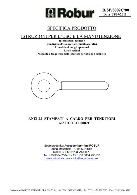
R/SP/8002C/00Date 08/09/2011PRODUCT SPECIFICATIONSOPERATING AND MAINTENANCE INSTRUCTIONSTechnical SpecificationsO<strong>per</strong>ating Conditions and LimitsO<strong>per</strong>ator’s InstructionsResidual RisksHow and how often <strong>per</strong>iodical fitness inspections should be conductedTURNBUCKLE EYES, HOT-PRESSEDITEM 8002CManufacturing site ROBUR wire rope accessoriesZona Industriale – C.da S. Nico<strong>la</strong>I-67039 SULMONA (L’AQUILA)Tel. +39.(0)864.2504.1 – Fax +39.(0)864.253132www.roburitaly.com – info@roburitaly.comDivision of BETA UTENSILI SPA, Via Volta, 18 - 20845 SOVICO (MB) ITALY Tel. +39.(0)39.20771-Fax + 39.(0)39.2010742
1) TECHNICAL SPECIFICATIONS OF ACCESSORYMaterial / Reference Standard: Steel S235JR - UNI EN 10025-2Heat Treatment: /Surface Treatment: Galvanized A2E EN ISO 4042The test is <strong>per</strong>formed on the basis of in-house <strong>specifica</strong>tions and rules in accordance with UNI EN ISO9001.Division of BETA UTENSILI SPA, Via Volta, 18 - 20845 SOVICO (MB) ITALY Tel. +39.(0)39.20771-Fax + 39.(0)39.2010742
DIMENSIONAL SPECIFICATIONS:TABLE “A”All measurements are expressed in mm.AA”E F H LgWIREROPE∅ minWFLkgITEM NUMBERRIGHT LEFTTHREAD THREADM18 11/16 103 28 59 179 400 7.0 1660 080020118 080020318A0M20 3/4 110 28 59 179 440 7.5 2130 080020120 080020320A0M22 7/8 120 34 70 200 660 9.0 2630 080020122 080020322A0M24 1” 130 36 76 218 850 10.0 3060 080020124 080020324A0M27 1”1/8 135 38 82 237 1200 11.0 4000 080020127 080020327A0M30 1”3/16 140 40 86 249 1400 11.5 4860 080020130 080020330A0M33 1”1/4 150 41 89 258 1600 12.0 6040 080020133 080020333A0- 1”3/8 150 43 95 266 2000 13.0 6500 080020198 080020398A0- 1”1/2 150 45 102 272 2300 14.0 7900 080020199 080020399A0WFL = WORKING FORCE LIMITSAFETY COEFFICIENT: 4Definitions:• WFL (working force limit): the maximum force the item can support (along the main axis, if nototherwise specified) under o<strong>per</strong>ating conditions.• Safety coefficient: guaranteed minimum breaking force to working force limit ratio.• Inspection: visual testing of the state of the item, to check for clear damage or wear which may affectits use.Division of BETA UTENSILI SPA, Via Volta, 18 - 20845 SOVICO (MB) ITALY Tel. +39.(0)39.20771-Fax + 39.(0)39.2010742
• Accurate examination: visual inspection <strong>per</strong>formed by a trained <strong>per</strong>son, supported, if need be, by anyother instruments, including non-destructive testing, to check for damage or wear which may affect theuse of the item.• Trained <strong>per</strong>son: a designated, suitably trained <strong>per</strong>son who has pro<strong>per</strong> know-how and practicalex<strong>per</strong>tise and has been given the instructions needed to <strong>per</strong>form any required tests and examinations.CAUTION:The safety coefficient is only provided by way of example, in re<strong>la</strong>tion to product safety.The working force limits (WFL) shown in the table should never be exceeded.2) TESTING SPECIFICATIONSThe item is subjected to several stringent tests for serviceability, <strong>per</strong>formance and compliance with<strong>specifica</strong>tions.The number of samples and the re<strong>la</strong>ted sampling p<strong>la</strong>ns are chosen according to the characteristic to testunder UNI ISO 2859/1, and the results are filed in the quality department of the factory in Sulmona.2.A Dimensional testMaking sure that the dimensions of the item meet such tolerances as established in inhouseworking drawings.2.B Visual testTesting for defects resulting from forming, mechanical working, surface coating andcorrespondence between the marking and in-house drawings.2.C Chemical analysisMaking sure that the chemical composition of the material complies with the limitsestablished under the relevant standards.2.D Tensile stress testsMaking sure that the accessory subjected to tensile stress will break, after the appliedforce has at least exceeded the working load as multiplied by the safety coefficient.The test is <strong>per</strong>formed in accordance with UNI 10002/1.Division of BETA UTENSILI SPA, Via Volta, 18 - 20845 SOVICO (MB) ITALY Tel. +39.(0)39.20771-Fax + 39.(0)39.2010742
3) HOW TO READ MARKINGSThe accessory carries the following indelible marks and codes:1) Manufacturer’s mark (R-ROBUR)4) GENERAL WARNINGSAs regards the information provided in these o<strong>per</strong>ating instructions, BETA UTENSILI SPA will accept noresponsibility in the event of:• any use of the accessories other than the uses under national safety and accident prevention<strong>la</strong>ws;• mistaken choice or arrangement of the apparatus they are going to be connected to;• failure to comply with, or pro<strong>per</strong>ly follow, the o<strong>per</strong>ating instructions;• changes to the accessories;• misuse or failure to carry out routine maintenance jobs;• use with noncompliant accessories.!CAUTION: The marking data should not be removed by grinding or abrasion (whetheraccidental or not – any items that do not carry any identification references should be madeunusable and scrapped).No characters other than the manufacturer’s may be affixed.Division of BETA UTENSILI SPA, Via Volta, 18 - 20845 SOVICO (MB) ITALY Tel. +39.(0)39.20771-Fax + 39.(0)39.2010742
5) SELECTION CRITERIAThe following parameters should be carefully considered in choosing the turnbuckle eye:5.A WORKING FORCE LIMITThe tensile stress exerted on the turnbuckle eye should be lower than or equal to the working force limit(WFL) recommended for the item being considered, and shown in Table “A”.5.B CONNECTING PARTMake sure that the connecting part suits the load capacity of the turnbuckle eye.The wire rope or any other component part being used should be of a suitable size (see Table “A”), toprevent cuts.5.C OPERATING TEMPERATURESThe <strong>per</strong>missible o<strong>per</strong>ating tem<strong>per</strong>ature should range between –20 °C and +80 °C.The working force limit will not be guaranteed outside this range.5.D LIFE AND FREQUENCY OF USEThe accessory is <strong>per</strong>fectly serviceable as long as its geometric and physical characteristics remainunchanged.Hence the turnbuckle eye should be rep<strong>la</strong>ced in case of reduced section, deformation, corrosion orconnecting instability.6) NONPERMISSIBLE CONDITIONSThe turnbuckle eyes should not be o<strong>per</strong>ated under the following circumstances:• when the applied force exceeds the <strong>per</strong>missible “WFL”;• when dynamic stresses or swinging loads may result;• when the turnbuckle eyes are o<strong>per</strong>ated under any tem<strong>per</strong>atures other than the <strong>per</strong>missibletem<strong>per</strong>atures;• when the directrix of forces does not develop along the main axis.7) PRELIMINARY TESTSBefore the accessories are o<strong>per</strong>ated and/or assembled, they should be tested by a suitably trained <strong>per</strong>son.• Check the state of the turnbuckle eye; in particu<strong>la</strong>r make sure that it is free from cuts,bends, indentations, abrasions, cracks, irregu<strong>la</strong>r threads, corrosions, sharp burrs, wearor defects resulting from impro<strong>per</strong> storage.• Measure and record the dimensions according to Table “A”.• Check the state of all the parts of the marking.• Make sure that the threads fit.Division of BETA UTENSILI SPA, Via Volta, 18 - 20845 SOVICO (MB) ITALY Tel. +39.(0)39.20771-Fax + 39.(0)39.2010742
8) INSTALLATION – ASSEMBLY INSTRUCTIONSScrew the turnbuckle eyes onto the turnbuckle body, so that maximum opening can be achieved, andconnect them to the parts to pull.Insert one rope or one part for each terminal.Exert tensile stress through the main body, making sure that, after the o<strong>per</strong>ating condition has beenreached, the turnbuckle eyes have been inserted into the body at least throughout the length of its thread.While exerting tensile stress, make sure that the turnbuckle can freely move and position itself; hence noforcing or interference should occur, to prevent any <strong>la</strong>teral force components from being produced.Tensile stress should be checked after a short <strong>per</strong>iod, to make up for any system adjustments.Particu<strong>la</strong>r attention is required while tensioning, to prevent the working force limit (WFL, see Table “A”)from being exceeded, which would result in <strong>per</strong>manent deformation, especially if any levers ormechanical means are used.9) USING ACCESSORY – GRIP AND HANDLINGThe turnbuckle eye is designed to be used in static situations; <strong>per</strong>iodically check tensile stress, the state ofpreservation of the parts and their connection, according to the Table “Maintenance jobs and inspections”.10) NONPERMISSIBLE USEUsing the accessory for any purposes other than the purposes it has been designed for, using it underextremely dangerous conditions and <strong>per</strong>forming poor maintenance may pose a severe hazard to thesafety of the people being exposed and cause severe damage to the working environment, whileaffecting the actual serviceability and safety of the product. The precautions mentioned below, which,obviously enough, cannot cover the whole spectrum of potential “misuses” of the accessory, should be“reasonably” deemed to be the most common steps to take. Therefore:• DO NOT connect the accessory to any apparatus which does not match its <strong>specifica</strong>tions interms of size, tem<strong>per</strong>ature, hook-up point and shape;• DO NOT use the accessory for lifting purposes;• DO NOT stretch any apparatus that may change its static configuration, centre of gravity orchemical and physical state;• DO NOT use the accessory in any apparatus designed to carry people or animals;• DO NOT use the accessory to pull restrained loads;• DO NOT work in areas where any explosion/spark-proof parts are expected to be used or inthe presence of big magnetic fields;• DO NOT weld any metal parts to the accessory; do not use any filling welds; do not use theaccessory as mass for any welder.11) FITNESS FOR USEThe accessory was tested for serviceability and <strong>per</strong>formance at the manufacturer’s. The certificatesupplied with it states that the tests were passed. However, before starting working, the user should testthe installed accessory for serviceability and <strong>per</strong>formance, to prove the entire system is fit for use.Division of BETA UTENSILI SPA, Via Volta, 18 - 20845 SOVICO (MB) ITALY Tel. +39.(0)39.20771-Fax + 39.(0)39.2010742
12) INSPECTION AND MAINTENANCEInspections and maintenance jobs should be carried out by trained <strong>per</strong>sonnel, who should <strong>per</strong>formaccurate tests during o<strong>per</strong>ation.Below is a list of tests to <strong>per</strong>form at such intervals as stated in the table “Maintenance jobs andinspections”.• VISUAL TEST: making sure that the accessory is free from surface defects, includingcracks, indentations, cuts, fissures and abrasions.• THREAD TEST: making sure that the thread is free from wear, deformation and dents, thatits fit is accurate and stable, and that there is not too much clearance.• DEFORMATION TEST: making sure that the accessory has not got deformed, using agauge to measure such critical dimensions as shown in Table “A”. NO DEFORMATIONSwill be tolerated compared to the measurements made when the accessory was first put intoo<strong>per</strong>ation.• WEAR TEST: making sure that the points of contact are not worn, using a gauge to measuresuch critical dimensions as shown in Table “A”.• PRESERVATION TEST: making sure that the accessory is free from oxidation andcorrosion, especially in case of outdoor use; using suitable methods (e.g. liquid penetrants)to make sure that it is free from cracks.The results of the above-mentioned tests should be stored.Maintenance jobs and inspectionsType of inspectionGeneral visual inspectionThread stateDeformationWearState of preservationWhenever used Month YearxxxxxIf the item has been used for heavy-duty jobs, both wear and the state of preservation should be tested formore frequently.13) SCRAPPING ACCESSORYThe accessory should be scrapped by cutting, so that it can no longer be used, whether at the end of itsexpected lifetime or if:- it is <strong>per</strong>manently worn compared to the original size;- any cracks or distortions are shown, and/or the sections have become small compared to theoriginal size;- the state of the thread is such that the parts do not fit <strong>per</strong>fectly, any threads are worn, deformed,irregu<strong>la</strong>r etc.Division of BETA UTENSILI SPA, Via Volta, 18 - 20845 SOVICO (MB) ITALY Tel. +39.(0)39.20771-Fax + 39.(0)39.2010742
R/SP/8002F/00Data 08/09/2011SPECIFICA PRODOTTOISTRUZIONI PER L’USO E LA MANUTENZIONEInformazioni tecnicheCondizioni d’uso previste e limiti o<strong>per</strong>ativiPrescrizioni <strong>per</strong> gli o<strong>per</strong>atoriRischi residuiModalità e frequenza delle ispezioni <strong>per</strong>iodiche d’idoneitàANELLI STAMPATI A FREDDO PER TENDITORIARTICOLO 8002FSede produttiva Accessori <strong>per</strong> funi ROBURZona Industriale – C.da S. Nico<strong>la</strong>67039 SULMONA (L’AQUILA)Tel. +39.0864.2504.1 – Fax +39.0864.253132www.roburitaly.com – info@roburitaly.comDivisione del<strong>la</strong> BETA UTENSILI SPA, Via Volta, 18 - 20845 SOVICO (MB) ITALY Tel. +39.039.20771-Fax + 39.039.2010742
1) CARATTERISTICHE TECNICHE DELL’ACCESSORIOMateriale / Norma di riferimento: acciaio CB 4 FF UNI 7356Trattamento Termico: /Trattamento Su<strong>per</strong>ficiale: Zincato A2E EN ISO 4042Il col<strong>la</strong>udo viene eseguito in base a specifiche e regole interne in riferimento al<strong>la</strong> norma UNI EN ISO9001.Divisione del<strong>la</strong> BETA UTENSILI SPA, Via Volta, 18 - 20845 SOVICO (MB) ITALY Tel. +39.039.20771-Fax + 39.039.2010742
CARATTERISTICHE DIMENSIONALI:TABELLA “A”Le quote indicate sono espresse in mm.A A E F H L WFL FUNECODICE”g kg ∅ min n DESTRI SINISTRIM5 3/16 37 8 16 56 8 115 2.0 200 080020105 080020305A0M6 1/4 40 10 20 65 15 160 2.5 150 080020106 080020306A0M8 5/16 52 11 22 79 27 300 2.5 100 080020108 080020308A0M10 3/8 60 14 27 96 52 470 3.5 100 080020110 080020310A0M11 7/16 65 15 29 103 71 580 3.5 / 080020111 080020311A0M12 1/2 72 17 33 113 90 690 4.0 50 080020112 080020312A0M14 9/16 85 18 35 128 135 940 4.0 / 080020114 080020314A0M16 5/8 95 23 46 146 225 1290 6.0 / 080020116 080020316A0WFL = FORZA LIMITE DI LAVOROCOEFFICIENTE DI SICUREZZA: 4Divisione del<strong>la</strong> BETA UTENSILI SPA, Via Volta, 18 - 20845 SOVICO (MB) ITALY Tel. +39.039.20771-Fax + 39.039.2010742
Definizioni:• WFL (working force limit): è <strong>la</strong> forza massima che l’articolo può sopportare (lungo l’asseprincipale se non diversamente indicato) in condizioni di utilizzo.• Coefficiente di sicurezza: è il rapporto tra <strong>la</strong> forza di rottura minima garantita e <strong>la</strong> forza limite di<strong>la</strong>voro.• Ispezione: controllo visivo re<strong>la</strong>tivo allo stato dell’elemento <strong>per</strong> individuare evidentidanneggiamenti o usure che possono alterarne l’utilizzo.• Esame accurato: esame visivo effettuato da una <strong>per</strong>sona competente e, se necessario, coadiuvatoda altri mezzi, quali i controlli non-distruttivi, al fine di individuare danneggiamenti o usure chepossono alterare l’utilizzo dell’articolo.• Persona competente: <strong>per</strong>sona designata, istruita correttamente, qualificata <strong>per</strong> conoscenza edes<strong>per</strong>ienza pratica, che ha ricevuto le <strong>istruzioni</strong> necessarie <strong>per</strong> eseguire le prove e gli esamirichiesti.ATTENZIONE: il coefficiente di sicurezza è soltanto un’indicazione <strong>per</strong> <strong>la</strong> sicurezza del <strong>prodotto</strong>.Non si devono mai su<strong>per</strong>are le forze (WFL) indicate nel<strong>la</strong> tabel<strong>la</strong>.2) SPECIFICHE DI COLLAUDOL’articolo è sottoposto a una serie di severi controlli <strong>per</strong> accertarne <strong>la</strong> funzionalità prestazionale e <strong>la</strong>rispondenza alle specifiche.La numerosità del campione e i re<strong>la</strong>tivi piani di campionamento sono scelti in funzione del<strong>la</strong>caratteristica da verificare in accordo e <strong>per</strong> quanto previsto dal<strong>la</strong> norma UNI ISO 2859/1, e i risultatiarchiviati nell’ufficio qualità dello stabilimento di Sulmona.2.A Controllo dimensionaleVerifica che le dimensioni dell’articolo rientrino nelle tolleranze stabilite dai re<strong>la</strong>tividisegni di costruzione interni.2.B Controllo visivoVerifica <strong>la</strong> presenza di eventuali im<strong>per</strong>fezioni dovute a stampaggio, <strong>la</strong>vorazionemeccanica, rivestimento su<strong>per</strong>ficiale.2.C Analisi chimicaVerifica <strong>la</strong> rispondenza del<strong>la</strong> composizione chimica del materiale, entro i limitistabiliti dalle re<strong>la</strong>tive norme.2.D Prove di trazioneVerifica che l’accessorio sottoposto a una trazione arrivi a rottura, dopo che <strong>la</strong> forzaapplicata abbia almeno su<strong>per</strong>ato il carico di <strong>la</strong>voro moltiplicato <strong>per</strong> il coefficiente disicurezza.La prova è eseguita in accordo con <strong>la</strong> norma UNI 10002/1.Divisione del<strong>la</strong> BETA UTENSILI SPA, Via Volta, 18 - 20845 SOVICO (MB) ITALY Tel. +39.039.20771-Fax + 39.039.2010742
3) AVVERTENZE GENERALICon riferimento a quanto riportato in queste <strong>istruzioni</strong> d’uso, <strong>la</strong> BETA UTENSILI SPA declina ogniresponsabilità in caso di:• uso degli accessori contrario alle leggi nazionali sul<strong>la</strong> sicurezza e sull’antinfortunistica;• errata scelta o predisposizione dell’apparecchio con il quale saranno connessi;• mancata o errata osservanza delle <strong>istruzioni</strong> <strong>per</strong> l’uso;• modifiche agli accessori;• uso improprio e omessa <strong>manutenzione</strong> ordinaria;• uso combinato ad accessori non conformi.4) CRITERI DI SCELTAI parametri che devono essere attentamente considerati nel<strong>la</strong> scelta dell’anello sono:5.A FORZA LIMITE DI LAVOROLa trazione esercitata sull’anello deve essere inferiore o uguale al valore del<strong>la</strong> forza limite di <strong>la</strong>voro(WFL) previsto <strong>per</strong> l’articolo preso in considerazione, e riportato nel<strong>la</strong> tabel<strong>la</strong> “A”.5.B ELEMENTO DI ACCOPPIAMENTOAssicurarsi che l’elemento di collegamento sia adeguato alle caratteristiche di portata dell’anello.La fune o qualsiasi altro componente utilizzato deve essere di dimensioni adeguate come da tabel<strong>la</strong>“A” , evitando così fenomeni di intaglio.5.C TEMPERATURE D’IMPIEGOLa tem<strong>per</strong>atura d’impiego consentita dovrà essere compresa tra –20 °C e +80 °C.Al di fuori di questi valori non è più garantita <strong>la</strong> forza limite di <strong>la</strong>voro.5.D VITA E FREQUENZA DI UTILIZZOL’accessorio <strong>la</strong>vora in <strong>per</strong>fetta efficienza fin quando restano invariate le sue caratteristichegeometriche e fisiche.Sostituire quindi l’anello quando si notano riduzioni di sezione, deformazioni, corrosioni o instabilitàdi accoppiamento.6) CONDIZIONI NON AMMESSENon è consentito far <strong>la</strong>vorare gli anelli nei seguenti casi:• quando <strong>la</strong> forza applicata è su<strong>per</strong>iore al “WFL” consentito;• nelle condizioni in cui si possono creare delle sollecitazioni di tipo dinamico o carichipulsanti;• far <strong>la</strong>vorare gli anelli a tem<strong>per</strong>ature diverse da quelle consentite;• quando <strong>la</strong> direttrice delle forze non si sviluppa lungo l’asse principale.Divisione del<strong>la</strong> BETA UTENSILI SPA, Via Volta, 18 - 20845 SOVICO (MB) ITALY Tel. +39.039.20771-Fax + 39.039.2010742
7) CONTROLLI PRELIMINARIPrima del<strong>la</strong> messa in servizio e/o del montaggio gli accessori devono essere control<strong>la</strong>ti da una<strong>per</strong>sona competente adeguatamente addestrata.• Control<strong>la</strong>re l’integrità dell’anello e in partico<strong>la</strong>re che non vi siano tagli, piegature,incisioni, abrasioni, incrinature o cricche, filetti irrego<strong>la</strong>ri, corrosioni, bavetaglienti, usure provocate dall’utilizzo o difetti dovuti a cattivo stoccaggio.• Rilevare e registrare le dimensioni con riferimento al<strong>la</strong> tabel<strong>la</strong> “A”.• Control<strong>la</strong>re l’integrità del<strong>la</strong> marcatura.• Verificare <strong>la</strong> bontà dell’accoppiamento tra i filetti.8) INSTALLAZIONE - ISTRUZIONI PER IL MONTAGGIOAvvitare gli anelli sul<strong>la</strong> canau<strong>la</strong> in maniera da ottenere l’a<strong>per</strong>tura massima e collegarli agli elementida mettere in trazione.Inserire solo una fune o un solo elemento <strong>per</strong> ogni terminale.Esercitare <strong>la</strong> trazione agendo sul corpo centrale, facendo attenzione che, una volta raggiunta <strong>la</strong>condizione di <strong>la</strong>voro, gli anelli siano inseriti nel corpo <strong>per</strong> almeno tutta <strong>la</strong> lunghezza del filetto diquest’ultimo.Nell’esercitare <strong>la</strong> trazione assicurarsi che il tenditore abbia piena libertà di movimento e diautoposizionamento; non devono quindi mai presentarsi forzature o interferenze che possanogenerare componenti di forza <strong>la</strong>terali.La condizione del<strong>la</strong> trazione deve essere control<strong>la</strong>ta dopo breve tempo <strong>per</strong> compensare eventualiadattamenti del sistema.Partico<strong>la</strong>re attenzione deve essere posta durante il tensionamento affinché non venga su<strong>per</strong>ata <strong>la</strong> forzalimite di <strong>la</strong>voro (WFL, vedi tabel<strong>la</strong> ”A”), <strong>per</strong> non incorrere in deformazioni <strong>per</strong>manenti, soprattuttonel caso si usino leve o mezzi meccanici.9) USO DELL’ACCESSORIO - PRESA E MANOVRAL’anello è stato concepito <strong>per</strong> essere utilizzato in situazioni statiche. Control<strong>la</strong>re <strong>per</strong>iodicamente lecondizioni del<strong>la</strong> trazione, lo stato di conservazione degli elementi e il loro accoppiamento, inriferimento al<strong>la</strong> tabel<strong>la</strong> “Interventi di <strong>manutenzione</strong> e controllo”.10) CONTROINDICAZIONI D’USOL’utilizzo dell’accessorio <strong>per</strong> scopi non previsti, il suo uso in condizioni estremamente <strong>per</strong>icolose e <strong>la</strong>carenza di <strong>manutenzione</strong> possono comportare gravi situazioni di <strong>per</strong>icolo <strong>per</strong> l’incolumità delle<strong>per</strong>sone esposte e di danno <strong>per</strong> l’ambiente di <strong>la</strong>voro, oltre che pregiudicare <strong>la</strong> funzionalità e <strong>la</strong>sicurezza effettiva del <strong>prodotto</strong>. Le azioni di seguito citate, che, ovviamente, non possono coprirel’intero arco di potenziali possibilità di “cattivo uso” dell’accessorio, costituiscono tuttavia quelle“ragionevolmente” più prevedibili. Quindi:• NON utilizzare l’accessorio collegandolo ad apparecchiature di dimensioni,tem<strong>per</strong>atura, punto d’aggancio e forma non idonei alle sue caratteristiche;• NON utilizzare l’accessorio <strong>per</strong> il sollevamento;Divisione del<strong>la</strong> BETA UTENSILI SPA, Via Volta, 18 - 20845 SOVICO (MB) ITALY Tel. +39.039.20771-Fax + 39.039.2010742
• NON mettere in tensione apparecchiature che possono cambiare <strong>la</strong> loro configurazionestatica, il loro baricentro o lo stato chimico-fisico;• NON utilizzare l’accessorio in apparecchiature destinate al trasporto di <strong>per</strong>sone oanimali;• NON usare l’accessorio <strong>per</strong> trainare carichi vinco<strong>la</strong>ti;• NON o<strong>per</strong>are in aree dove è prescritto l’uso di componenti antidef<strong>la</strong>granti/antiscintil<strong>la</strong> oin presenza di forti campi magnetici;• NON saldare sull’accessorio partico<strong>la</strong>ri metallici, né intervenire con riporti di saldaturao utilizzarlo come massa <strong>per</strong> saldatrici.11) IDONEITÀ ALL’UTILIZZOL’accessorio è stato sottoposto a col<strong>la</strong>udo presso il costruttore <strong>per</strong> accertare <strong>la</strong> rispondenza funzionalee prestazionale dello stesso. L’attestato che accompagna <strong>la</strong> fornitura certifica il su<strong>per</strong>amento con esitopositivo dei test di col<strong>la</strong>udo. L’utilizzatore deve eseguire in ogni caso, prima di iniziare a o<strong>per</strong>are, <strong>la</strong>verifica del<strong>la</strong> rispondenza funzionale e prestazionale dell’accessorio instal<strong>la</strong>to <strong>per</strong> confermarel’idoneità all’impiego dell’intera instal<strong>la</strong>zione.12) ISPEZIONE E MANUTENZIONEComprende una serie di o<strong>per</strong>azioni eseguite da <strong>per</strong>sonale competente istruito allo scopo, re<strong>la</strong>tive acontrolli ed esami accurati durante l’impiego.Di seguito l’elenco dei controlli da effettuare con cadenze indicate nel<strong>la</strong> tabel<strong>la</strong> “Interventi di<strong>manutenzione</strong> e controllo”.• VISIVO: verificare l’assenza di difetti su<strong>per</strong>ficiali, quali cricche, incisioni, tagli ofessure, abrasioni.• CONDIZIONI DEL FILETTO: esaminare lo stato del filetto, che non deve presentareusure, deformazioni e ammaccature, e l’accoppiamento deve essere preciso, stabile esenza eccessivo gioco.• DEFORMAZIONE: verificare che l’accessorio non sia deformato, misurando con uncalibro le dimensioni critiche, come indicato nel<strong>la</strong> tabel<strong>la</strong> “A”. NON sono tolleratedeformazioni rispetto alle quote rilevate al<strong>la</strong> prima messa in servizio.• USURA: verificare che i punti di contatto non siano usurati, misurando con un calibrole dimensioni critiche indicate nel<strong>la</strong> tabel<strong>la</strong> “A”.• STATO DI CONSERVAZIONE: verificare l’assenza di ossidazione e corrosione,soprattutto in caso di utilizzo all’a<strong>per</strong>to; verificare l’assenza di cricche con metodiidonei (p. es. liquidi penetranti).Le registrazioni di questi controlli devono essere conservate.Divisione del<strong>la</strong> BETA UTENSILI SPA, Via Volta, 18 - 20845 SOVICO (MB) ITALY Tel. +39.039.20771-Fax + 39.039.2010742
Tabel<strong>la</strong> interventi di <strong>manutenzione</strong> e controlloTipo di controlloControllo visivo gener.Condizioni del filettoDeformazioneUsuraStato di conservazioneA ogni utilizzo Mese AnnoxxxxxNel caso in cui l’articolo sia sottoposto a un utilizzo gravoso, è necessario effettuare le verifiche diusura e stato di conservazione con maggiore frequenza.13) DEMOLIZIONE E ROTTAMAZIONE DELL’ACCESSORIOL’accessorio deve essere demolito mediante taglio, in modo tale che non possa più essere utilizzato,sia al termine del<strong>la</strong> vita prevista, che nel caso presenti:- una deformazione <strong>per</strong>manente rispetto al<strong>la</strong> misura originale;- eventuali cricche, distorsioni e/o se si riscontrano riduzioni di sezione rispetto al<strong>la</strong> misuraoriginale;- se le condizioni del filetto non garantiscono il <strong>per</strong>fetto accoppiamento tra le parti, filettiusurati, deformati, irrego<strong>la</strong>ri ecc.Divisione del<strong>la</strong> BETA UTENSILI SPA, Via Volta, 18 - 20845 SOVICO (MB) ITALY Tel. +39.039.20771-Fax + 39.039.2010742
R/SP/8002F/00Date 08/09/2011PRODUCT SPECIFICATIONSOPERATING AND MAINTENANCE INSTRUCTIONSTechnical SpecificationsO<strong>per</strong>ating Conditions and LimitsO<strong>per</strong>ator’s InstructionsResidual RisksHow and how often <strong>per</strong>iodical fitness inspections should be conductedTURNBUCKLE EYES, COLD-PRESSEDITEM 8002FManufacturing site ROBUR wire rope accessoriesZona Industriale – C.da S. Nico<strong>la</strong>67039 SULMONA (L’AQUILA)Tel. +39.(0)864.2504.1 – Fax +39.(0)864.253132www.roburitaly.com – info@roburitaly.comDivision of BETA UTENSILI SPA, Via Volta, 18 - 20845 SOVICO (MB) ITALY Tel. +39.(0)39.20771-Fax + 39.(0)39.2010742
1) TECHNICAL SPECIFICATIONS OF ACCESSORYMaterial / Reference Standard: Steel CB 4 FF UNI 7356Heat Treatment: /Surface Treatment: Galvanized A2E EN ISO 4042The test is <strong>per</strong>formed on the basis of in-house <strong>specifica</strong>tions and rules in accordance with UNI ENISO 9001.Division of BETA UTENSILI SPA, Via Volta, 18 - 20845 SOVICO (MB) ITALY Tel. +39.(0)39.20771-Fax + 39.(0)39.2010742
DIMENSIONAL SPECIFICATIONS:ATABLE “A”All measurements are expressed in mm.A”E F H LgWFLkgWIREROPE∅ minnITEM NUMBERRIGHT LEFTTHREAD THREADM5 3/16 37 8 16 56 8 115 2.0 200 080020105 080020305A0M6 1/4 40 10 20 65 15 160 2.5 150 080020106 080020306A0M8 5/16 52 11 22 79 27 300 2.5 100 080020108 080020308A0M10 3/8 60 14 27 96 52 470 3.5 100 080020110 080020310A0M11 7/16 65 15 29 103 71 580 3.5 / 080020111 080020311A0M12 1/2 72 17 33 113 90 690 4.0 50 080020112 080020312A0M14 9/16 85 18 35 128 135 940 4.0 / 080020114 080020314A0M16 5/8 95 23 46 146 225 1290 6.0 / 080020116 080020316A0WFL = WORKING FORCE LIMITSAFETY COEFFICIENT: 4Division of BETA UTENSILI SPA, Via Volta, 18 - 20845 SOVICO (MB) ITALY Tel. +39.(0)39.20771-Fax + 39.(0)39.2010742
Definitions:• WFL (working force limit): the maximum force the item can support (along the main axis, if nototherwise specified) under o<strong>per</strong>ating conditions.• Safety coefficient: guaranteed minimum breaking force to working force limit ratio.• Inspection: visual testing of the state of the item, to check for clear damage or wear which mayaffect its use.• Accurate examination: visual inspection <strong>per</strong>formed by a trained <strong>per</strong>son, supported, if need be, byany other instruments, including non-destructive testing, to check for damage or wear which mayaffect the use of the item.• Trained <strong>per</strong>son: a designated, suitably trained <strong>per</strong>son who has pro<strong>per</strong> know-how and practicalex<strong>per</strong>tise and has been given the instructions needed to <strong>per</strong>form any required tests andexaminations.CAUTION:The safety coefficient is only provided by way of example, in re<strong>la</strong>tion to productsafety.The working force limits (WFL) shown in the table should never be exceeded.2) TESTING SPECIFICATIONSThe item is subjected to several stringent tests for serviceability, <strong>per</strong>formance and compliance with<strong>specifica</strong>tions.The number of samples and the re<strong>la</strong>ted sampling p<strong>la</strong>ns are chosen according to the characteristic totest under UNI ISO 2859/1, and the results are filed in the quality department of the factory inSulmona.2.A Dimensional testMaking sure that the dimensions of the item meet such tolerances as established inin-house working drawings.2.B Visual testTesting for defects resulting from forming, mechanical working and surface coating.2.C Chemical analysisMaking sure that the chemical composition of the material complies with the limitsestablished under the relevant standards.2.D Tensile stress testsMaking sure that the accessory subjected to tensile stress will break, after the appliedforce has at least exceeded the working load as multiplied by the safety coefficient.The test is <strong>per</strong>formed in accordance with UNI 10002/1.Division of BETA UTENSILI SPA, Via Volta, 18 - 20845 SOVICO (MB) ITALY Tel. +39.(0)39.20771-Fax + 39.(0)39.2010742
3) GENERAL WARNINGSAs regards the information provided in these o<strong>per</strong>ating instructions, BETA UTENSILI SPA wil<strong>la</strong>ccept no responsibility in the event of:• any use of the accessories other than the uses under national safety and accidentprevention <strong>la</strong>ws;• mistaken choice or arrangement of the apparatus they are going to be connected to;• failure to comply with, or pro<strong>per</strong>ly follow, the o<strong>per</strong>ating instructions;• changes to the accessories;• misuse or failure to carry out routine maintenance jobs;• use with noncompliant accessories.4) SELECTION CRITERIAThe following parameters should be carefully considered in choosing the turnbuckle eye:5.A WORKING FORCE LIMITThe tensile stress exerted on the turnbuckle eye should be lower than or equal to the working forcelimit (WFL) recommended for the item being considered, and shown in Table “A”.5.B CONNECTING PARTMake sure that the connecting part suits the load capacity of the turnbuckle eye.The wire rope or any other component part being used should be of a suitable size (see Table “A”), toprevent cuts.5.C OPERATING TEMPERATURESThe <strong>per</strong>missible o<strong>per</strong>ating tem<strong>per</strong>ature should range between –20 °C and +80 °C.The working force limit will not be guaranteed outside this range.5.D LIFE AND FREQUENCY OF USEThe accessory is <strong>per</strong>fectly serviceable as long as its geometric and physical characteristics remainunchanged.Hence the turnbuckle eye should be rep<strong>la</strong>ced in case of reduced section, deformation, corrosion orconnecting instability.6) NONPERMISSIBLE CONDITIONSThe turnbuckle eyes should not be o<strong>per</strong>ated under the following circumstances:• when the applied force exceeds the <strong>per</strong>missible “WFL”;• when dynamic stresses or swinging loads may result;• when the turnbuckle eyes are o<strong>per</strong>ated under any tem<strong>per</strong>atures other than the<strong>per</strong>missible tem<strong>per</strong>atures;• when the directrix of forces does not develop along the main axis.Division of BETA UTENSILI SPA, Via Volta, 18 - 20845 SOVICO (MB) ITALY Tel. +39.(0)39.20771-Fax + 39.(0)39.2010742
7) PRELIMINARY TESTSBefore the accessories are o<strong>per</strong>ated and/or assembled, they should be tested by a suitably trained<strong>per</strong>son.• Check the state of the turnbuckle eye; in particu<strong>la</strong>r make sure that it is free fromcuts, bends, indentations, abrasions, cracks, irregu<strong>la</strong>r threads, corrosions, sharpburrs, wear or defects resulting from impro<strong>per</strong> storage.• Measure and record the dimensions according to Table “A”.• Check the state of all the parts of the marking.• Make sure that the threads fit.8) INSTALLATION – ASSEMBLY INSTRUCTIONSScrew the turnbuckle eyes onto the turnbuckle body, so that maximum opening can be achieved, andconnect them to the parts to pull.Insert one rope or one part for each terminal.Exert tensile stress through the main body, making sure that, after the o<strong>per</strong>ating condition has beenreached, the turnbuckle eyes have been inserted into the body at least throughout the length of itsthread.While exerting tensile stress, make sure that the turnbuckle can freely move and position itself; henceno forcing or interference should occur, to prevent any <strong>la</strong>teral force components from being produced.Tensile stress should be checked after a short <strong>per</strong>iod, to make up for any system adjustments.Particu<strong>la</strong>r attention is required while tensioning, to prevent the working force limit (WFL, see Table“A”) from being exceeded, which would result in <strong>per</strong>manent deformation, especially if any levers ormechanical means are used.9) USING ACCESSORY – GRIP AND HANDLINGThe turnbuckle eye is designed to be used in static situations; <strong>per</strong>iodically check tensile stress, thestate of preservation of the parts and their connection, according to the Table “Maintenance jobs andinspections”.10) NONPERMISSIBLE USEUsing the accessory for any purposes other than the purposes it has been designed for, using it underextremely dangerous conditions and <strong>per</strong>forming poor maintenance may pose a severe hazard to thesafety of the people being exposed and cause severe damage to the working environment, whileaffecting the actual serviceability and safety of the product. The precautions mentioned below, which,obviously enough, cannot cover the whole spectrum of potential “misuses” of the accessory, shouldbe “reasonably” deemed to be the most common steps to take. Therefore:• DO NOT connect the accessory to any apparatus which does not match its<strong>specifica</strong>tions in terms of size, tem<strong>per</strong>ature, hook-up point and shape;• DO NOT use the accessory for lifting purposes;Division of BETA UTENSILI SPA, Via Volta, 18 - 20845 SOVICO (MB) ITALY Tel. +39.(0)39.20771-Fax + 39.(0)39.2010742
• DO NOT stretch any apparatus that may change its static configuration, centre ofgravity or chemical and physical state;• DO NOT use the accessory in any apparatus designed to carry people or animals;• DO NOT use the accessory to pull restrained loads;• DO NOT work in areas where any explosion/spark-proof parts are expected to be usedor in the presence of big magnetic fields;• DO NOT weld any metal parts to the accessory; do not use any filling welds; do not usethe accessory as mass for any welder.11) FITNESS FOR USEThe accessory was tested for serviceability and <strong>per</strong>formance at the manufacturer’s. The certificatesupplied with it states that the tests were passed. However, before starting working, the user shouldtest the installed accessory for serviceability and <strong>per</strong>formance, to prove the entire system is fit for use.12) INSPECTION AND MAINTENANCEInspections and maintenance jobs should be carried out by trained <strong>per</strong>sonnel, who should <strong>per</strong>formaccurate tests during o<strong>per</strong>ation.Below is a list of tests to <strong>per</strong>form at such intervals as stated in the table “Maintenance jobs andinspections”.• VISUAL TEST: making sure that the accessory is free from surface defects, includingcracks, indentations, cuts, fissures and abrasions.• THREAD TEST: making sure that the thread is free from wear, deformation and dents,that its fit is accurate and stable, and that there is not too much clearance.• DEFORMATION TEST: making sure that the accessory has not got deformed, using agauge to measure such critical dimensions as shown in Table “A”. NODEFORMATIONS will be tolerated compared to the measurements made when theaccessory was first put into o<strong>per</strong>ation.• WEAR TEST: making sure that the points of contact are not worn, using a gauge tomeasure such critical dimensions as shown in Table “A”.• PRESERVATION TEST: making sure that the accessory is free from oxidation andcorrosion, especially in case of outdoor use; using suitable methods (e.g. liquidpenetrants) to make sure that it is free from cracks.The results of the above-mentioned tests should be stored.Division of BETA UTENSILI SPA, Via Volta, 18 - 20845 SOVICO (MB) ITALY Tel. +39.(0)39.20771-Fax + 39.(0)39.2010742