datasensor bws-t4n series
datasensor bws-t4n series
datasensor bws-t4n series

You also want an ePaper? Increase the reach of your titles
YUMPU automatically turns print PDFs into web optimized ePapers that Google loves.
DATASENSORBWS-T4N SERIESBarriera di sicurezza pluriraggio di livello 41 … 4 coppie di fotocelluleMultiray safety barrier, level 4,1 … 4 pairs of photocellsMANUALE ISTRUZIONIINSTRUCTIONS MANUAL1
WARRANTYDATASENSOR S.p.A. warrants its products to be free fromdefects.DATASENSOR S.p.A. will repair or replace, free of charge,any product found to be defective during the warranty periodof 36 months from the manufacturing date.This warranty does not cover damage or liability derivingfrom the improper application of DATASENSOR products.DATASENSOR S.p.A. Via Lavino 26540050 Monte S. Pietro - Bologna - ItalyTel: +39 051 6765611 Fax: +39 051 6759324http://www.<strong>datasensor</strong>.com e-mail: info@<strong>datasensor</strong>.comCONDIZIONI DI GARANZIADATASENSOR S.p.A. garantisce i suoi prodotti esenti dadifetti.DATASENSOR S.p.A. riparerà o sostituirà, gratuitamente,ogni prodotto che riterrà difettoso durante il periodo digaranzia di 36 mesi dalla data di fabbricazione.La garanzia non copre danneggiamenti o responsabilitàdovute ad un uso non corretto del prodotto.PRODUCER: TECHNO-GR s.r.l.DATASENSOR S.p.A. reserves the right to make modifications and improvements without prior notification.DATASENSOR S.p.A. si riserva il diritto di apportare modifiche e/o miglioramenti senza preavviso.826000872 Rev.BDECLARATION OF CONFORMITYWeDATASENSOR S.p.A.Via Lavino, 26540050 Monte San PietroBologna - Italydeclare under our sole responsibility that the product(s)BWS-T4N AND BWS-T4N-MT SAFETY CONTROLLER (TYPE4)to which this declaration relates in conformity with the followingstandard(s) or other normative document(s)CEI EN 55022, JUNE 1997:LIMITS AND METHODS OF MEASUREMENTS OF RADIO DISTURBANCE OF INFORMATIONTECHNOLOGY EQUIPMENTCEI EN 61000-4-2, SEPTEMBER 1996:ELECTROMAGNETIC COMPATIBILITY (EMC). PART 4: TESTING AND MEASUREMENTTECHNIQUES. SECTION 2: ELECTROSTATIC DISCHARGE IMMUNITY TESTCEI EN 61000-4-3, NOVEMBER 1997:ELECTROMAGNETIC COMPATIBILITY (EMC). PART 4: TESTING AND MEASUREMENTTECHNIQUES. SECTION 3: RADIATED, RADIO-FREQUENCY, ELECTROMAGNETIC FIELDIMMUNITY TESTCEI EN 61000-4-4, SEPTEMBER 1996:ELECTROMAGNETIC COMPATIBILITY (EMC). PART 4: TESTING AND MEASUREMENTTECHNIQUES. SECTION 4: ELECTRICAL FAST TRANSIENT/BURST IMMUNITY TESTCEI EN 61000-4-5, JUNE 1997:ELECTROMAGNETIC COMPATIBILITY (EMC). PART 4: TESTING AND MEASUREMENTTECHNIQUES. SECTION 5: SURGE IMMUNITY TESTCEI EN 61000-4-6, NOVEMBER 1997:ELECTROMAGNETIC COMPATIBILITY (EMC). PART 4: TESTING AND MEASUREMENTTECHNIQUES. SECTION 6: IMMUNITY TO CONDUCTED DISTURBANCES, INDUCED BYRADIO-FREQUENCY FIELDSCEI IEC 61496-2, NOVEMBER 1997:SAFETY OF MACHINERY - ELECTRO-SENSITIVE PROTECTIVE EQUIPMENT - PART 2:PARTICULAR REQUIREMENTS FOR EQUIPMENT USING ACTIVE OPTO-ELECTRONICPROTECTIVE DEVICES (AOPDS)Following the provision of the Directive(s):89/336 CEE AND SUCCESSIVE AMENDMENTSMonte San Pietro, 02/01/2001Gianni StradiottiUNI EN ISO 14001Quality Assurance Manager2
BWS-T4N Series Instructions manual Serie BWS-T4N Manuale istruzioniINDEX1. BEFORE USING THE DEVICE .........................................................11.1. GENERAL INSTRUCTIONS..............................................................................11.2. ROUTINE MAINTENANCE ...............................................................................11.3. AGRO-FOOD INDUSTRIES..............................................................................12. GENERAL INFORMATION AND MAIN APPLICATIONS ................23. OPERATION ......................................................................................44. PRECAUTIONS AND INSTALLATION CRITERIA...........................64.1. CALCULATION OF THE MINIMUM INSTALLATION DISTANCE......................64.2. REFLECTIVE SURFACES................................................................................65. CONNECTIONS .................................................................................75.1. REFERENCES ON THE TERMINAL BOARD ...................................................75.2. WIRING EXAMPLE...........................................................................................85.3. CODES AND DESCRIPTION OF THE AVAILABLE PHOTOCELLS ...............106. ALIGNMENT PROCEDURE ............................................................117. OPERATING PROCEDURES..........................................................127.1. DIP-SWITCHES CONFIGURATION................................................................127.2. CONFIGURATION OF THE NUMBER OF PHOTOCELLS..............................127.3. MUTING FUNCTION.......................................................................................137.3.1. DESCRIPTION ...................................................................................137.3.2. INSTALLATION CRITERIA.................................................................137.4. OVERRIDE .....................................................................................................187.5. STARTING THE OVERRIDE FUNCTION .......................................................187.6. TIMING RESTRICTIONS (muting function). ....................................................187.7. LED DIAGNOSTIC..........................................................................................198. FINAL CHECKS...............................................................................209. ROUTINE MAINTENANCE OPERATIONS.....................................2010. GENERAL INFORMATION AND USEFUL DATA..........................2111. TECHNICAL DATA..........................................................................2212. DISPLAY OPERATIVE CODES ......................................................2312.1. OPERATIVE STATE SIGNALINGS.................................................................2312.2. FAILURE SIGNALINGS ..................................................................................2313. OVERALL DIMENSIONS ................................................................25INDICE1. PRIMA DELL’UTILIZZO.................................................................... 11.1. INDICAZIONI GENERALI................................................................................. 11.2. MANUTENZIONE PERIODICA......................................................................... 11.3. INDUSTRIE AGRO-ALIMENTARI..................................................................... 12. GENERALITÀ E PRINCIPALI APPLICAZIONI ................................ 23. FUNZIONAMENTO ........................................................................... 44. PRECAUZIONI E CRITERI DI INSTALLAZIONE............................. 64.1. CALCOLO DELLA DISTANZA MINIMA DI INSTALLAZIONE ........................... 64.2. SUPERFICI RIFLETTENTI ............................................................................... 65. COLLEGAMENTI .............................................................................. 75.1. RIFERIMENTI SULLA MORSETTIERA ............................................................ 75.2. ESEMPIO DI CABLAGGIO............................................................................... 85.3. CODICI E DESCRIZIONE DELLE FOTOCELLULE DISPONIBILI ...................106. PROCEDURA DI ALLINEAMENTO ............................................... 117. PROCEDURE OPERATIVE ............................................................ 127.1. CONFIGURAZIONE DEI DIP-SWITCH............................................................127.2. CONFIGURAZIONE DEL NUMERO DI FOTOCELLULE.................................127.3. FUNZIONE DI MUTING...................................................................................137.3.1. DESCRIZIONE.......................................................................................137.3.2. CRITERI DI INSTALLAZIONE................................................................137.4. OVERRIDE......................................................................................................187.5. AVVIO DELLA FUNZIONE OVERRIDE...........................................................187.6. VINCOLI TEMPORALI (funzione di muting).....................................................187.7. DIAGNOSTICA A LED.....................................................................................198. CONTROLLI FINALI ....................................................................... 209. OPERAZIONI DI MANUTENZIONE PERIODICA........................... 2010. INFORMAZIONI GENERALI E DATI UTILI.................................... 2111. DATI TECNICI ................................................................................. 2212. CODICI OPERATIVI DISPLAY ....................................................... 2312.1. SEGNALAZIONI DI STATO OPERATIVO. ......................................................2312.2. SEGNALAZIONI DI GUASTO..........................................................................2313. DIMENSIONI D’INGOMBRO........................................................... 25
BWS-T4 Series Instructions manual Serie BWS-T4 Manuale istruzioni1. BEFORE USING THE DEVICE1.1. GENERAL INSTRUCTIONSTo guarantee a correct installation, carefully follow the instructions ofthis manual.Do not touch non-insulated cables, unless they have beendisconnected upstream.Make sure that the cables connected to the control unit are not tootaut and that they do not hinder the movement of persons or things.The control unit does not contain parts subject to maintenance;before carrying out any outer operation, turn off the power.Do not open the container for any reason and in case of failure, sendit to our laboratories by possibly indicating the detected failure andthe operation period.Avoid touching the protective cover of the lenses with the hands inorder to prevent dust and/or grease from infiltrating the device, thusreducing the system performances.The possible wear of the protective covers does not compromise thesystem safety in any way but can cause a system locking.1.2. ROUTINE MAINTENANCENo special operations are necessary apart from the cleaning of theoptical units.Do not use woollen clothes.Do not use solvents.According to the room conditions, estimate the frequency of thisoperation.DATASENSOR S.p.A. refuses any responsibility for damage topersons or things due to the incorrect use of the device.1.3. AGRO-FOOD INDUSTRIESThis device does not require washing and rinsing but simply the lenscleaning by means of a soft cloth dampened with water; anyway,apply to the producer to make sure that possible chemical agentsused during the production processes cannot damage the photocells.1. PRIMA DELL’UTILIZZO1.1. INDICAZIONI GENERALIPer una corretta installazione attenersi scrupolosamente alleistruzioni di questo manuale.Non toccare cavi non isolati a meno che siano stati sconnessi amonte.Assicurarsi che i cavi collegati all’unità di controllo non sianoeccessivamente tesi e che non siano di intralcio al movimento dipersone o cose.L’unità di controllo non contiene parti soggette a manutenzione,prima di effettuare qualsiasi intervento esterno toglierel’alimentazione.Non aprire il contenitore per alcun motivo, ed in caso di guastoinviarla ai nostri laboratori possibilmente indicando l’anomaliariscontrata ed il periodo di funzionamento.Evitare di toccare la copertura protettiva delle lenti con le mani ondeevitare che polvere e/o grasso riducano le prestazioni.L’eventuale deterioramento delle coperture protettive noncompromette in alcun modo la sicurezza del sistema ma puòprovocare il blocco dello stesso.1.2. MANUTENZIONE PERIODICANon sono richiesti interventi di alcun genere ad esclusione dellapulizia delle parti ottiche.Non utilizzare panni di lana.Non utilizzare solventi.Valutare a seconda delle condizioni degli ambienti la periodicità diquesto intervento.La DATASENSOR S.p.A. declina ogni responsabilità per danni apersone o cose dovuti al non coretto utilizzo dell’apparecchiatura.1.3. INDUSTRIE AGRO-ALIMENTARIL’apparecchiatura non necessita di lavaggi e sciacquature, masemplicemente della pulizia delle lenti con un panno morbidoinumidito con acqua; consultare comunque il costruttore perverificare che eventuali agenti chimici utilizzati nei processi produttivinon siano dannosi per le fotocellule.1 1
BWS-T4 Series Instructions manual Serie BWS-T4 Manuale istruzioni2. GENERAL INFORMATION AND MAIN APPLICATIONSThe multiray safety barrier of the BWS-T4N <strong>series</strong> has been produced tomeet the need to protect persons in areas where it is necessary toguarantee the safety of the operator using machines, robots or ingeneral automatic systems which are considered dangerous or subjectto casual or undesired access to unsafe parts.The system conforms with the requirements for safety devices of level 4in compliance with what described in the latest international standards,that is to say IEC 61496 1-2.This safety device is made up of a control unit protected by a plasticcontainer so that it can be installed on a DIN/OMEGA guide; it has 32screw terminals to which it is possible to connect from 1 to 4 pairs ofphotocells.This version of the multi-ray safety barrier has the double ‘muting’function, by means of this function it is possible to connect or disconnectone or more pair of photocells in order to allow - for instance - thematerial passage without stopping the machine. If the device has thisfunction, an other function must be also possible: The ‘override’ function.It represents the possibility to force the system, that is to say to close theoutput relays even with occupied rays in order to make it possible for thematerial which has gathered before the optical devices to proceed.Both the muting and the override functions represent a system forcing;for this reason, to activate these functions some precautions limiting thereduction of the safety level have been added.The presence of a limb or an object interrupting a beam causes theopening of the emergency exits and the consequent locking of the dulyconnected machine. It is necessary for the barrier to be connected in theright position in comparison with the passage to be protected in such away that there isn’t any possibility to climb over.Here is a list of the commonly used applications: Machines for the processing of wood, glass and ceramicproducts. Automatic warehouses. Conveying lines. Palletizers2. GENERALITÀ E PRINCIPALI APPLICAZIONILa barriera pluriraggio di sicurezza della serie BWS-T4N è statarealizzata per coprire le esigenze di protezione di persone in ambientinei quali è necessario garantire l'incolumità dell'operatore che utilizzimacchine, robot o in generale sistemi automatici pericolosi o passibili diaccesso casuale o indesiderato a parti non sicure.Il sistema risponde ai requisiti per le apparecchiature di sicurezza dilivello 4, in conformità a quanto descritto nelle più recenti normeinternazionali, in particolare la IEC 61496 1-2.Questo dispositivo di sicurezza è costituito da una centralina incontenitore plastico per montaggio su guida DIN/OMEGA, dotato di 32morsetti a vite ai quali è possibile collegare da1 a 4 coppie di fotocellule.Questa versione della barriera di sicurezza pluriraggio dispone dellafunzione di doppio ‘muting’, mediante la quale è possibile includere odescludere una o più coppie di fotocellule, al fine di consentire, adesempio, il passaggio di materiale senza che questo comporti il fermodella macchina. Quando il dispositivo è dotato di questa funzione,occorre anche che un’altra funzione sia possibile: la funzione chiamata‘override’. In pratica rappresenta la possibilità di forzare il sistema, cioépermette di chiudere i relé di uscita anche a raggi impegnati, perconsentire ad eventuale materiale accumulato davanti alle ottiche, dipoter transitare.Sia il muting che l’override rappresentano una forzatura del sistema equindi per attivare tali funzioni sono previste alcune precauzioni chelimitano il degrado del livello di sicurezza.La presenza quindi di un arto o di un oggetto che interrompe un fascioprovoca l'apertura delle uscite di sicurezza ed il conseguente bloccodella macchina collegata, che sarà collegata in maniera opportuna adessa. È fondamentale che le fotocellule siano collegate nella giustaposizione rispetto al varco da proteggere in modo che non esistanopossibilità di scavalcamento.Applicazioni di uso comune sono: Macchine di lavorazione legno, vetro, ceramica. Magazzini automatici. Linee di trasporto. Pallettizzatori2 2
BWS-T4 Series Instructions manual Serie BWS-T4 Manuale istruzioniThe barrier has been planned with reference to the following standards:La progettazione della barriera è stata eseguita con riferimento alleseguenti norme:IEC 61496-1: 1997.FDIS IEC 61496-2: 1997.Safety of machinery: electro-sensitiveprotective devices- General requirements and test.Safety of machinery: electro-sensitiveprotective devices- Particular requirements for systemusing active opto-electronic devices.IEC 61496-1: 1997.FDIS IEC 61496-2: 1997.Safety of machinery: electro-sensitiveprotective devices- General requirements and test.Safety of machinery: electro-sensitiveprotective devices- Particular requirements for systemusing active opto-electronic devices.3 3
BWS-T4 Series Instructions manual Serie BWS-T4 Manuale istruzioni3. OPERATIONThe control electronic system is fitted inside the control unit. The ‘core’of the device is made up of two microprocessors forming - as requiredby the standards - a system having “two independent channels”. Bymeans of the suitable hardware, they continuously control and check theconnected photocells. No interference among the photocells is possibleas they are controlled sequentially; it will be thus possible to install twoor more adjacent photocells. When one or more rays are interrupted, theelectronic system opens the output relays signalling which photocellshave triggered by means of LEDs which can be seen on the container. Adisplay supplies information on the state and on possible failures.The control-unit can work in two different modes (please refer to par.7)which he can carry out the following operations:• TEST/RESET button: It is used to check if the whole system -made up of the output relays of the control unit and the machineactuator - works effectively. By pressing this button (opening thecontact) you practically simulate the interruption of one or moresafety rays and check that the machine stops according to theestablished times and modes.• START/RESTART button: It is used to start the system which hasbeen just powered - in case you are in a condition of manual reset- and to start it again when it has locked after a relay triggering (ifyou are in a condition of manual reset) or after an error which canbe reset (see table relating to the error codes).Two types of different operating modes are also available:1. Automatic restoring, that is to say after the triggering caused bythe detection of an object: The barrier starts to work againnormally when the object is removed.2. Manual reset by means of the reset button so that the return tothe normal operating mode takes place only after the object hasbeen removed and the button has been pressed.During the barrier working, no operation set by means of the userinterface involves functions which can influence the system safety.These barriers have also a model with muting function on each opticaldevice. During the operation, this feature makes it possible to connect ordisconnect any available optical device from the protection function byrespecting special times.3. FUNZIONAMENTOL’elettronica di controllo è alloggiata all’interno della centralina.Il cuore del dispositivo è costituito da due microprocessori checostituiscono, come richiesto dalle normative, un sistema a “due canaliindipendenti”.Essi provvedono mediante l’apposito hardware, a pilotare e verificarecontinuamente le fotocellule collegate. Quando uno o più raggi vengonointerrotti, l’elettronica provvede ad aprire i relè di uscita, segnalandomediante led visibili sul contenitore quali fotocellule sono intervenute.Un display provvede a fornire indicazioni sullo stato e su eventualianomalie.L'utente dispone di due pulsanti con i quali può compiere le seguentioperazioni:• Pulsante di TEST/RESET: serve a verificare se tutto il sistemacostituito da relè di uscita della centralina più l’attuatore dellamacchina è efficiente. Premendo tale pulsante (aprendo ilcontatto) in pratica simuliamo l’interruzione di uno o più raggi disicurezza e verifichiamo che la macchina si fermi nei tempi e neimodi definiti.• Pulsante di START/RESTART: serve ad avviare il sistemaappena alimentato, nel caso ci troviamo in condizioni di ripristinomanuale, ed a riavviarlo quando è in blocco a seguito di unintervento (se siamo in condizioni di ripristino manuale) o di unerrore ripristinabile (vedi tabella codici di errore).La centralina può operare in due diverse modalità di funzionamento(riferirsi al paragrafo 7):1. Ripristino automatico, cioè dopo l'intervento causato dalrilevamento di un oggetto, la barriera riprende il normalefunzionamento nel momento in cui l'oggetto viene rimosso.2. Ripristino manuale, attraverso il pulsante di ripristino per cui ilritorno alla modalità operativa normale avviene solo dopo chel'oggetto è stato rimosso e che il pulsante è stato premuto.Durante il funzionamento della barriera nessuna operazione impostataattraverso l'interfaccia utente coinvolge funzioni che possano influiresulla sicurezza del sistema.Queste barriere dispongono inoltre di un modello con funzione di mutingsu ciascuna ottica. Tale caratteristica permette durante il funzionamento,nel rispetto di particolari tempistiche, di escludere o includere dallafunzione di protezione una qualsiasi delle ottiche disponibili.4 4
BWS-T4 Series Instructions manual Serie BWS-T4 Manuale istruzioniThe optical devices which must be set on muting during the operationcan be pre-set by the user by means of a dip-switch (please refer to par.7.1).Even the models showing this feature can be both with manual andautomatic restoring.Le ottiche che durante il funzionamento dovranno essere poste inmuting, possono essere preimpostate dall’utente mediante un dip-switch(riferirsi paragrafo 7.1).Anche i modelli che dispongono di questa caratteristica possono esseresia con ripristino manuale che automatico.5 5
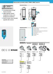
BWS-T4 Series Instructions manual Serie BWS-T4 Manuale istruzioni4. PRECAUTIONS AND INSTALLATION CRITERIAThe area on which the barrier must be installed must be compatiblewith the technical features of the device; room temperature, troublesof electromagnetic, luminous or other character must be previouslyevaluated possibly applying to the producer for data which are notreported on this manual.4.1. CALCULATION OF THE MINIMUM INSTALLATION DISTANCEThe safety distance ‘S’ must be sufficient to guarantee that thedangerous area cannot be reached by the operator up to the momentin which the machine with moving part stops. The formula used tocalculate the safety distance for multiray barriers is the following one:STKCS = ( K * T ) + C= safety distance.= T1 + T2whereas T1 = machine response time in seconds.T2 = barrier response time in seconds.= 1600 mm/s (speed of the body approaching the dangerous area).= 850 mm (1200 mm for systems with single optical unit).The height of ray from earth, in case of multirays barrier, are defined in following table:4 rays 3 rays 2 raysheight of 1º ray 300 mm 300 mm 400 mmheight of 2º ray 600 mm 700 mm 900 mmheight of 3º ray 900 mm 1100 mm --height of 4º ray 1200 mm -- --4. PRECAUZIONI E CRITERI DI INSTALLAZIONEL’ambiente in cui deve essere installata la barriera, deve esserecompatibile con le caratteristiche tecniche del dispositivo;temperatura ambientale, disturbi di natura elettromagnetica eluminosa e altro, vanno valutati a priori eventualmente consultando ilcostruttore per dati non presenti in questo manuale.4.1. CALCOLO DELLA DISTANZA MINIMA DI INSTALLAZIONELa distanza di sicurezza ‘S’ deve essere tale da assicurare che lazona di pericolo non possa essere raggiunta dall’operatore, fino ache la macchina con l’organo in movimento sia ferma. La formula percalcolare la distanza di sicurezza per barriere multiraggio è laseguente:S = ( K * T ) + CSTKC= distanza di sicurezza.= T1 + T2dove T1 = tempo di risposta della macchina in secondi.T2 = tempo di risposta della barriera in secondi.= 1600 mm/s (velocità di avvicinamento del corpo alla zonapericolosa).= 850 mm (1200 mm per sistemi con ottica singola).L'altezza dei raggi da terra nel caso di sbarramenti pluriraggio deve rispettare latabella che segue:4 raggi 3 raggi 2 raggialtezza del 1º raggio 300 mm 300 mm 400 mmaltezza del 2º raggio 600 mm 700 mm 900 mmaltezza del 3º raggio 900 mm 1100 mm --altezza del 4º raggio 1200 mm -- --4.2. REFLECTIVE SURFACESIn case reflecting surfaces are present, the distance must be sufficient toavoid the possibility of passive reflections.4.2. SUPERFICI RIFLETTENTINel caso siano presenti superfici riflettenti occorre che la distanza siasufficiente da garantire che non esistano riflessioni passive.reflective materialreflective materialRX barATX barRX barATX bar2° 2°2°2°ObjectA2° 2°2°2°ObjectAreflective materialreflective material6 6
BWS-T4 Series Instructions manual Serie BWS-T4 Manuale istruzioni5. CONNECTIONS5.1. REFERENCES ON THE TERMINAL BOARDHere is a table reporting the function and the connection to be carriedout for each number which is present on the label near the terminalboard:TERMINALOUTER CONNECTION1 - 2 Connect to the 24 Vdc power supply, respecting the polarity indicated on the label.3 - 4 Start/restart button; connect a normally opened button (N.O.).4 - 5 Test/reset button; connect a normally closed button (N.C.).6 - 7 Connect the muting signaller.8 Input of the muting A sensor. Connect to the N.O. contact of the muting sensor (photocell, proximityswitch, other).9 Input of the muting B sensor. Connect to the N.O. contact of the muting sensor (photocell, proximityswitch, other).10 Input of the muting C sensor. Connect to the N.O. contact of the muting sensor (photocell, proximityswitch, others)11 Input of the muting D sensor. Connect to the N.O. contact of the muting sensor (photocell, proximityswitch, others)12 Terminal not used.13 - 14 Safety output 1 with N.O. contact.15 - 16 Safety output 2 with N.O. contact.17 - 18 Power supply emitters (TX), photocells 1 and 2. Brown wires (pin 1 of connector) to terminal 17, bluewires (pin 3 of connector) to terminal 18. (in case of photocell S30 with terminal board, connect 17and 18 respectively with 1 and 2 of the photocell)19 - 20 Connect the photocells 1 and 2 to the test input of emitters (TX). Black wire (pin 4 of connector) TX 1on terminal 19, black wire TX 2 on terminal 20. (in case of photocell S30 with terminal board, connectthese terminals with 3 of the photocell)21 - 22 Power supply emitters (TX), photocells 3 and 4. Brown wires (pin 1 of connector) to 21 terminal, bluewires (pin 3 of connector) to terminal 22. (in case of photocell S30 with terminal board, connect 21and 22 respectively with 1 and 2 of the photocell)23 - 24 Connect photocells 3 and 4 to the test input of emitters (TX). Black wire (pin 4 of connector) TX 3 onterminal 23, black wire TX 4 on terminal 24. (in case of photocell S30 with terminal board, connectthese terminals with 3 of the photocell)25 - 26 Power supply receivers (RX), photocells 1 and 2. Brown wires (pin 1 of connector) to terminal 25,blue wires (pin 3 of connector) to terminal 26. (in case of photocell S30 with terminal board, connect25 and 26 respectively with 1 and 2 of the photocell)27 - 28 Connect to the PNP output of the receivers (RX) photocells 1 and 2. Black wire (pin 4 of connector)RX1 on terminal 27, black wire RX2 on terminal 28 (in case of photocell S30 with terminal board,connect these terminals with 6 of the photocell)29 - 30 Power supply receivers (RX), photocells 3 and 4. Brown wires (pin 1 of connector) to terminal 29,blue wires (pin 3 of connector) to terminal 30. (in case of photocell S30 with terminal board, connect29 and 30 respectively with 1 and 2 of the photocell)31 - 32 Connect to the PNP output of the receivers (RX) photocells 3 and 4. Black wire (pin 4 of connector)RX3 on terminal 31, black wire RX4 on terminal 32 (in case of photocell S30 with terminal board,connect these terminals with 6 of the photocell).5. COLLEGAMENTI5.1. RIFERIMENTI SULLA MORSETTIERAViene riportata una tabella nella quale sono indicati per ciascunnumero presente sull’etichetta a fianco della morsettiera, la relativafunzione ed il collegamento da effettuare:MORSETTOCOLLEGAMENTO ESTERNO1 - 2 Connettere alla alimentazione 24 Vdc, rispettando la polarità indicata sull’etichetta3 - 4 Pulsante di start/restart; collegare un pulsante normalmente aperto (N.A.)4 - 5 Pulsante di test/reset; collegare un pulsante normalmente chiuso (N.C.)6 - 7 Collegare il segnalatore di muting8 Ingresso del sensore di muting A. Collegare al contatto N.A. del sensore di muting (fotocellula,proximity, altro)9 Ingresso del sensore di muting B. Collegare al contatto N.A. del sensore di muting (fotocellula,proximity, altro)10 Ingresso del sensore di muting C. Collegare al contatto N.A. del sensore di muting (fotocellula,proximity, altro)11 Ingresso del sensore di muting D. Collegare al contatto N.A. del sensore di muting (fotocellula,proximity, altro)12 Morsetto non utilizzato13 - 14 Uscita di sicurezza 1 con contatto N.A.15 - 16 Uscita di sicurezza 2 con contatto N.A.17 - 18 Alimentazione emettitori (TX) fotocellule 1 e 2. Fili marroni (pin 1 del connettore) al morsetto 17, filiblu (pin 3 del connettore) al morsetto 18 (nel caso di fotocellula S30 con morsettiera collegare 17 e18 rispettivamente con 1 e 2 della fotocellula)19 - 20 Collegare all’ingresso di test dei emettitori (TX) fotocellule 1 e 2. Filo nero (pin 4 del connettore) TX1sul morsetto 19, filo nero TX2 sul morsetto 20 (nel caso di fotocellula S30 con morsettiera collegarequesti morsetti con il 3 della fotocellula)21 - 22 Alimentazione emettitori (TX) fotocellule 3 e 4. Fili marroni (pin 1 del connettore) al morsetto 21, filiblu (pin 3 del connettore) al morsetto 22 (nel caso di fotocellula S30 con morsettiera collegare 21 e22 rispettivamente con 1 e 2 della fotocellula)23 - 24 Collegare all’ingresso di test dei emettitori (TX) fotocellule 3 e 4. Filo nero (pin 4 del connettore) TX3sul morsetto 23, filo nero TX4 sul morsetto 24 (nel caso di fotocellula S30 con morsettiera collegarequesti morsetti con il 3 della fotocellula)25 - 26 Alimentazione ricevitori (RX) fotocellule 1 e 2. Fili marroni (pin 1 del connettore) al morsetto 25, fili blu(pin 3 del connettore) al morsetto 26 (nel caso di fotocellula S30 con morsettiera collegare 25 e 26rispettivamente con 1 e 2 della fotocellula)27 - 28 Collegare all’uscita PNP dei ricevitori (RX) fotocellule 1 e 2. Filo nero (pin 4 del connettore) RX1 sulmorsetto 27, filo nero RX2 sul morsetto 28 (nel caso di fotocellula S30 con morsettiera collegarequesti morsetti con il 6 della fotocellula).29 - 30 Alimentazione ricevitori (RX) fotocellule 3 e 4. Fili marroni (pin 1 del connettore) al morsetto 29, fili blu(pin 3 del connettore) al morsetto 30 (nel caso di fotocellula S30 con morsettiera collegare 29 e 30rispettivamente con 1 e 2 della fotocellula)31 - 32 Collegare all’uscita PNP dei ricevitori (RX) fotocellule 3 e 4. Filo nero (pin 4 del connettore) RX3 sulmorsetto 31, filo nero RX4 sul morsetto 32 (nel caso di fotocellula S30 con morsettiera collegarequesti morsetti con il 6 della fotocellula).7 7
BWS-T4 Series Instructions manual Serie BWS-T4 Manuale istruzioni5.2. WIRING EXAMPLEHere is a connection example of the control unit BWS-T4N relating toa mixed configuration in which all the available models of photocellshave been used.5.2. ESEMPIO DI CABLAGGIODi seguito viene riportato un esempio di collegamento dell'unità dicontrollo BWS-T4N relativa ad una configurazione mista, nella qualesono utilizzati tutti i modelli di fotocellule tra quelli disponibili.MAIN SUPPLYGNDMutingA-BMutingC-DALIMENTAZIONEPRINCIPALEGNDMutingA-BMutingC-D24 VDCEXTERNALFUSETERMINAL BOARD INSIDE TOS30 TYPE PHOTOCELLSTARTN.A.TESTN.C.EXTERNALLAMPMutingsensorcontatcsN.O.Safety output 1Safety output 224 VDCFUSIBILEESTERNOSTARTN.A.TESTN.C.LAMPADAESTERNAContatti deisensori dimutingN.A.Contatto 1 disicurezzaContatto 2 disicurezza1+MORSETTIERA INTERNA ALLAFOTOCELLULA TIPO S3023456-TESTPNP OUT1 2 3 4 5 6 7 8 9 10 11 12 13 14 15 16BWS-T4Ncontrol unitN.C.17 18 19 20 21 22 23 24 25 26 27 28 29 30 31 32123456+-TESTPNP OUT1 2 3 4 5 6 7 8 9 10 11 12 13 14 15 16BWS-T4N-MTcontrol unitN.C.17 18 19 20 21 22 23 24 25 26 27 28 29 30 31 32M12 MALE CONNECTORMOUNTED ON PHOTOCELL2 1+ brownbleu blackbleu blackbrown blackbrown black+ - pnp out+ - testCONNETTORE M12 MASCHIOSULLA FOTOCELLULAblu neromarrone neroblu neromarrone nero+ - pnp out+ - test3 42 1+marronebleu-TESTblackPNP OUTS5 TYPEEmitterS5 TYPEReceiverS30 TYPEEmitterS30 TYPEReceiverblu -3 4TESTPNP OUTneroS5 TYPEEmettitoreS5 TYPERicevitoreS30 TYPEEmettitoreS30 TYPERicevitoreS10 TYPEEmitterS10 TYPEReceiverS10 TYPEEmettitoreS10 TYPERicevitore8 8
BWS-T4 Series Instructions manual Serie BWS-T4 Manuale istruzioniPlease, note especially what follows:• Three out of four photocells have been connected choosingamong the ones which can be used; model S5-5 has beenconnected to the terminals reòating to TX1-RX1, model S10-5 tothe ones of TX2-RX2, the terminals of TX3-RX3 have not beenused and TX4-RX4 has been connected to model S30-5.To configure the control unit in such a way that it works only withthree present photocells, it has been necessary to connect theunused emitter output to the input of the corresponding receiver,in this case to terminal TEST-TX3 with PNP_OUT-RX3.All models can be connected in all the possible combinations fora maximum of four pairs of sensors with at least one pairconnected.• The transformer which is necessary to power the system mustconform to standard EN 60742 (double insulation) or with equalinsulation, for instance VDE 0551.• It is necessary to protect the control unit with an outer fusehaving a nominal interruption current equal to 1 A.• The TEST and START pushbuttons must be positioned in such away that the operator can see the protected area when herestarts, or carries out a test or override operation.• The outer light device for active muting signalling must bepositioned in a place where it can be seen from any operativepoint.• Read the paragraph relating to the muting function and its usefor the positioning of the activation sensors of this function.• Both safety contacts OUT1 and OUT2 must be connected. If themachine has a single locking circuit, the two normally openedcontacts must be connected in <strong>series</strong>.• Photocells of the type S5-5 and S10-5 are delivered with wiredcable or standard M12 connector and the wiring on the controlunit is indicated according to the cable colour, or to the maleconnector pin number.• Photocells of the type S30-5 are available also in the versionwith terminal board; in this case, it is necessary to carry out theconnections by respecting the same symbols present both onthe terminal board of the control until and on the photocell one.In particolare si noti quanto segue:• Sono state collegate tre fotocellule su quattro tra quelle chepossono essere utilizzate; il modello S5-5 è stato collegato aimorsetti relativi alla coppia TX1-RX1, il modello S10-5 a quellidella coppia TX2-RX2, i morsetti della coppia TX3-RX3 non sonostati utilizzati, e la coppia TX4-RX4 è stata collegata con ilmodello S30-5.Si può notare che per configurare l'unità di controllo ad operaresolamente con tre fotocellule presenti, è stato necessarioconnettere l'uscita del trasmettitore non utilizzato con l'ingressodel corrispondente ricevitore, in questo caso il morsetto TEST-TX3 con PNP_OUT-RX3.Tutti i modelli possono essere collegati in tutte le combinazionipossibili per un massimo di quattro coppie di sensori, con almenouna coppia collegata.• ll trasformatore necessario ad alimentare il sistema deve essereconforme alla norma EN 60742 (doppio isolamento), oppure conisolamento equivalente, es. VDE 0551.• È necessario proteggere l'unità di controllo con un fusibileesterno, che abbia una corrente di interruzione nominale di 1 A.• I pulsanti di TEST e di START devono essere posizionati inmodo che l'operatore possa visionare la zona protetta quandoeffettua l'operazione di riavvio, di test o di override.• Il dispositivo luminoso esterno di segnalazione di muting attivodeve essere posizionato in un luogo che sia visibile da tutti i latioperativi.• Leggere il paragrafo relativo alla funzione di muting ed al suoutilizzo per il posizionamento dei sensori di attivazione di talefunzione.• Entrambi i contatti di sicurezza OUT1 e OUT2 devono esserecollegati. Se la macchina prevede un solo circuito di blocco sidevono collegare in serie i due contatti N.A.• Le fotocellule del tipo S5-5 e S10-5 sono fornite con il cavocablato o con connettore M12 standard, ed il cablaggio sull'unitàdi controllo è indicato in relazione al colore del cavo od allanumerazione del connettore maschio.• Le fotocellule del tipo S30-5 sono disponibili anche con versionea morsettiera; in questo caso occorre effettuare i collegamentirispettando la stessa simbologia presente sia sulla morsettieradell'unità di controllo che in quella della fotocellula.9 9
BWS-T4 Series Instructions manual Serie BWS-T4 Manuale istruzioni• The connection cables of the photocells, of muting request, startand test must be masked with minimum section 22AWG.The screen braids must be all earthed towards the control unitside.In the following paragraph you can find the codes of the availablemodels which can be used in the wished configuration.5.3. CODES AND DESCRIPTION OF THE AVAILABLEPHOTOCELLSMODEL S5-5CODE TYPE CONTAINERS5-5-G8-60-ST4 sender plastic, with 5m of cableS5-5-G8-62-ST4 sender plastic, with connector M12S5-5-F8-90-ST4 receiver plastic, with 5m of cableS5-5-F8-92-ST4 receiver plastic, with connector M12MODEL S10-5CODE TYPE CONTAINERS10-5-G8-60-ST4 sender metal, with 5m of cableS10-5-G8-62-ST4 sender metal, with connector M12S10-5-F8-90-ST4 receiver metal, with 5m of cableS10-5-F8-92-ST4 receiver metal, with connector M12MODEL S30-5CODE TYPE CONTAINERS30-5-G50-1ST4 sender plastic, connection to terminal boardS30-5-G50-2ST4 sender plastic, with connector M12S30-5-F50-1ST4 receiver plastic, connection to terminal boardS30-5-F50-2PST4 receiver plastic, with connector M12• I cavi di collegamento delle fotocellule, di richiesta di muting, distart e test devono essere schermati, con sezione minima22AWG. Le calze dello schermo devono essere collegate tutte aterra verso il lato centralina.Nel paragrafo successivo sono riportati i codici dei modelli disponibiliad essere utilizzati nella configurazione desiderata.5.3. CODICI E DESCRIZIONE DELLE FOTOCELLULE DISPONIBILIMODELLO S5-5CODICE TIPO CONTENITORES5-5-G8-60-ST4 emettitore plastico, con 5m di cavoS5-5-G8-62-ST4 emettitore plastico, con connettore M12S5-5-F8-90-ST4 ricevitore plastico, con 5m di cavoS5-5-F8-92-ST4 ricevitore plastico, con connettore M12MODELLO S10-5CODICE TIPO CONTENITORES10-5-G8-60-ST4 emettitore metallico, con 5m di cavoS10-5-G8-62-ST4 emettitore metallico, con connettore M12S10-5-F8-90-ST4 ricevitore metallico, con 5m di cavoS10-5-F8-92-ST4 ricevitore metallico, con connettore M12MODELLO S30-5CODICE TIPO CONTENITORES30-5-G50-1ST4 emettitore plastico, connessione a morsettieraS30-5-G50-2ST4 emettitore plastico, con connettore M12S30-5-F50-1ST4 ricevitore plastico, connessione a morsettieraS30-5-F50-2PST4 ricevitore plastico, con connettore M1210 10
BWS-T4 Series Instructions manual Serie BWS-T4 Manuale istruzioni6. ALIGNMENT PROCEDUREAfter having carried out the correct mechanical assembly and thecorrect connections as described in the previous paragraphs, it isnecessary to align the pairs of photocells. Follow the operativemodes as follows:• Turn off the power supplying the control unit.• Open the test contact.• Power the control unit.• Align the photocells by observing the LEDs on the control unit:If the alignment of the relevant pair of photocell is correct, theLED is turned on.• After the alignment, turn off the power supplying the controlunit, close the test contact and power the control unit again.• Wait for the control unit to carry out the initial tests, visualizingon the display a count-down which indicates the control unitactivity.• At the end of this operation, the display will visualize letter ‘A’indicating the active state of the control unit.• Carry out all the checks described in the final checks and inthe routine maintenance operations.During aligning operations or normal working, check that the photocellsconnected to the same or other units do not interfere which each other,modifying their mutual position, for instance by positioning some pairs ofemitters on the other receiver side.6. PROCEDURA DI ALLINEAMENTODopo avere effettuato il corretto montaggio meccanico ed i corretticollegamenti come descritto nei paragrafi precedenti occorreallineare le copie di fotocellule. Seguire le modalità operative diseguito descritte:• Togliere l’alimentazione all’unità di controllo.• Aprire il contatto di test.• Alimentare l’unità di controllo.• Allineare le fotocellule guardando i led posti sulla centralina: aled acceso corrisponde un corretto allineamento della relativacoppia di fotocellule.• Ad allineamento concluso, togliere l’alimentazione allacentralina, chiudere il contatto di test e rialimentare lacentralina.• Attendere che la centralina esegua i test iniziali, visualizzandosul display un count-down che indica l’attività della centralina.• Al termine di tale operazione il display visualizzerà la lettera ‘A’che indica lo stato attivo della centralina.• Procedere a tutte le verifiche descritte nei controlli finali e nelleoperazioni di manutenzione periodica.Durante le operazioni di allineamento o durante il normalefunzionamento verificare che le fotocellule collegate alla stessa o adaltre unità non interferiscano tra loro, modificando la posizionereciproca, ad esempio posizionando alcune coppie di emettitori dal latodegli altri ricevitori.11 11
BWS-T4 Series Instructions manual Serie BWS-T4 Manuale istruzioni7. OPERATING PROCEDURES7.1. DIP-SWITCHES CONFIGURATIONThe configuration indicated in table must be selected on both the dipswitchpresent on the side of the control unit, after to have removed thecap of protection. The description corresponding to the pre-choosenselection is reported.7. PROCEDURE OPERATIVE7.1. CONFIGURAZIONE DEI DIP-SWITCH.La configurazione indicata in tabella deve essere selezionata suentrambi i dip-switch presenti sul fianco della centralina, dopo averasportato il tappo di protezione: si riporta la descrizionecorrispondente alla selezione prescelta:1 functionXnot used2 functionOff muting A-B act on the sensor couples 1and 2.muting C-D act on the sensor couples 3and 4.On muting A-B act on the sensor couple 1.muting C-D act on the sensor couple 2.The sensor couples 3-4 continue tofunction normally.ONSW 143211234SW 2ONNOTE: configure the two dipswitchin the same waj,otherwisethe central control unit is lockedand code '8' is displayed.1 funzioneXnon utilizzato2 funzioneOffOnmuting A-B agiscono sulle coppie disensori 1 e 2muting C-D agiscono sulle coppie disensori 3 e 4muting A-B agiscono sulla coppia disensori 1muting C-D agiscono sulla coppia disensori 2le coppie di sensori 3-4 continuanoad operare normalmenteONSW143211234SW2ONNOTA BENE: configurare i duedip-switch nello stesso modo, incaso contrario la centralina andràin blocco visualizzando il codice '8'sul display.3 function 4 functionOff muting 60 s Off manual restoringOn muting ∞ s On automatic restoringThe control-unit is manufactured from the factory with the followingconfiguration:• Automatic restoring, all four optics in muting, the maximumduration of the muting is of sixteen seconds.7.2. CONFIGURATION OF THE NUMBER OF PHOTOCELLSIn case you use a number of photocells which is lower than 4, operateas follows: to disconnect the photocells do not use and therefore do notconnect to the control unit; carry out a connection among the followingterminals:unused photocellconnection1 19 to 272 20 to 283 23 to 314 24 to 323 funzione 4 funzioneOff muting 60 s Off ripristino manualeOn muting ∞ s On ripristino automaticoLa centralina esce dalla fabbrica configurata nel seguente modo:• Ripristino automatico, tutte 4 le ottiche in muting, duratamassima del muting di 60 secondi.7.2. CONFIGURAZIONE DEL NUMERO DI FOTOCELLULEIn caso di utilizzo di un numero di fotocellule inferiore a 4 agire comesegue:per escludere le fotocellule non utilizzate e quindi non collegateall’unità di controllo fare un collegamento tra i seguenti morsetti:fotocellula non utilizzatacollegamento1 19 con 272 20 con 283 23 con 314 24 con 32At least one pair of photocells must be connected, otherwise (conditionof all the disconnected photocells) the control unit is locked.12 12
BWS-T4 Series Instructions manual Serie BWS-T4 Manuale istruzioniAlmeno una coppia di fotocellule deve essere collegata, in casocontrario (condizione con tutte le fotocellule escluse) la centralina siblocca.13 13
BWS-T4 Series Instructions manual Serie BWS-T4 Manuale istruzioni7.3. MUTING FUNCTION.7.3.1. DESCRIPTION.The muting function makes it possible to connect or disconnectone or more optical devices during the operation according to theoperative needs. As required by the standard, the control unit hastwo inputs for the activation of this function. Two separate mutingfunctions are present.It is necessary to duly connect the muting sensors in order to avoidthat a wrong positioning can cause undesired muting requests. It isnevertheless necessary to remember that the muting functionrepresents a system forcing and for this reason it must be usedwith care.By means of the inner DIP-SWITCHES, it is possible to decidewhich optical units must be set on muting (that is to say, whichoptical units must be disconnected) after a request (see DIP-SWITCHES setting).To use the muting function, it is necessary also to connect themuting signaller without which the control unit locks.7.3.2. INSTALLATION CRITERIA1. The muting sensors must recognise the material (namely pallets,vehicles, etc.) in all its length.2. The sensors must be arranged in such a way that the material isrecognised even when it must be lifted for the relevant processing.3. In case of different transport speeds in the muting area, alwaysbear in mind their influence on the muting total duration.4. All the safety photocells and the muting sensors must be arrangedin such a way that the previous material has already passed thelast muting sensor before the new material has reached the firstsensors.S37.3. FUNZIONE DI MUTING7.3.1. DESCRIZIONELa funzione di muting consente di escludere o includere una o piùottiche durante il funzionamento, in relazione alle esigenzeoperative. La centralina è dotata, come richiesto dalla normativa,di due ingressi per l’attivazione di ogni funzione di muting; dueseparate funzioni di muting sono presenti.E’ necessario collegare opportunamente i sensori di muting ondeevitare che un cattivo posizionamento, possa essere causa dirichieste di muting indesiderate. Occorre comunque ricordare chela funzione di muting rappresenta pur sempre una forzatura delsistema, e che quindi va utilizzata con le dovute cautele.E’ possibile mediante i DIP-SWITCHES, decidere quali ottichedovranno andare in muting (essere escluse) a seguito di unarichiesta. (vedere impostazione dei DIP-SWITCHES).Per utilizzare la funzione di muting è necessario collegare anche ilsegnalatore esterno di muting senza il quale la centralina siblocca.7.3.2. CRITERI DI INSTALLAZIONE1. I sensori del muting devono riconoscere il materiale (i.e. pallet,veicoli, ..) in tutta la sua lunghezza.2. I sensori devono essere disposti in modo che il materiale vengariconosciuto anche quando debba essere sollevato per lalavorazione.3. Nel caso di diverse velocità di trasporto nel campo del mutingtenere in considerazione il loro effetto sulla durata totale delmuting.4. Tutte le fotocellule di sicurezza ed i sensori di muting devonoessere disposti in modo che il materiale precedente abbia giàpassato l’ultimo sensore di muting prima che il nuovo materialeabbia raggiunto i primi sensori.S3S2S2S1S1B2 A2B1 A1B2 A2B1 A114 14
BWS-T4 Series Instructions manual Serie BWS-T4 Manuale istruzioniIn the previous page, an installation example of a protection arrangedon a conveyor is drawn; it must allow the passage of package 1,preventing other packages from passing or it must allow the passageof packages 1 and 2, preventing package 3 from passing. Theprotection photocells S are connected to the BWS-T4N control unitand are temporaneously cut-out at the package passage by means ofthe muting A1, A2, B1 and B2 activation sensors.Sensors A and B are optical, mechanical, proximity, etc. sesnors withclosed contact in the presence of the object to be detected.In both cases, the configuration dip-switch 2 must be set in the onposition.Application with four muting sensors, passage permitted only for package 1:B2 A2SB1 A1d1DLvcontact of A1contact of A2contact of B1contact of B2Muting sensor connection:24 VDCN.C.N.C.BWS-T4Nterminals11 MUTE C10 MUTE D9 MUTE A8 MUTE BApplication with four muting sensors, passage permitted only for packages 1 and 2:Muting sensor connection:Nella pagina precedente è disegnato un esempio di installazione di unaprotezione disposta su un trasportatore che deve consentire il passaggio delpacco 1 impedendo il passaggio degli altri, oppure deve permettere il passaggiodel pacco 1 e 2 impedendo il passaggio del pacco 3. Le fotocellule di protezioneS vengono collegate all'unità di controllo BWS-T4N e vengonotemporaneamente escluse al passaggio del pacco per mezzo dei sensori diattivazione del muting A1, A2, B1 e B2.I sensori A e B sono sensori ottici, meccanici, di prossimità, etc., con contattochiuso in presenza dell'oggetto da rilevare.In entrambi i casi in esame il dip-switch 2 di configurazione deve essere postonella posizione on.Applicazione con quattro sensori di muting, caso di passaggio permesso solo al pacco1:Collegamento dei sensori di muting:B2 A2SB1 A1d1DLvcontatto di A1contatto di A2contatto di B1contatto di B224 VDCN.C.morsettieraBWS-T4N11 MUTE C10 MUTE D9 MUTE A8 MUTE BApplicazione con quattro sensori di muting, caso di passaggio permesso al pacco 1 e 2:N.C.Collegamento dei sensori di muting:24 VDCLvcontact of A124 VDC11 MUTE C10 MUTE DLvcontatto di A1contatto di A211 MUTE C10 MUTE D9 MUTE AB2 A2SB1 A1d1Dcontact of A2contact of B1contact of B29 MUTE A8 MUTE BBWS-T4-MTterminalsB2 A2SB1 A1d1Dcontatto di B1contatto di B2morsettieraBWS-T4N8 MUTE B15 15
BWS-T4 Series Instructions manual Serie BWS-T4 Manuale istruzioniApplication with two muting sensors, passage permitted only for package 1:Muting sensor connection:Applicazione con due sensori di muting e caso di passaggio permesso solo al pacco 1:Collegamento dei sensori di muting:24 VDCN.C.11 MUTE C24 VDCN.C.11 MUTE CN.C.10 MUTE DN.C.10 MUTE Dcontact of A9 MUTE Acontatto di A9 MUTE ABSAd1 = Dcontact of BBWS-T4Nterminals8 MUTE BD: minimum distance sdo that the muting sensors keepactive the request; it depends on the parcel length: D
BWS-T4 Series Instructions manual Serie BWS-T4 Manuale istruzioniMuting sensor connection:Collegamento dei sensori di muting:24 VDC24 VDCLvcontact of A1N.C.N.C.11 MUTE C10 MUTE DLvcontatto di A1N.C.N.C.11 MUTE C10 MUTE Dcontact of A29 MUTE Acontatto di A29 MUTE AB2 A2SB1 A1d1Dcontact of B1contact of B2BWS-T4Nterminals8 MUTE BB2 A2SB1 A1d1Dcontatto di B1contatto di B28 MUTE BmorsettieraBWS-T4NThe examples above are thought for the use of the muting functions onlyrelating to sensors S1 and S2, with the configuration DIP-SWITCH 2 inthe off positions; sensors S1 and S2 are controlled by the muting A andB inputs, while sensors S3 and S4 are controlled by the muting C and Dinputs. His configuration makes other applications be possible.Application with eight muting sensors and output and input controlWe imagine an area in which a manipulator acts; the barriers in inputand output must allow the poassage of the packages only when themanipulator has terminated its work, thus avoiding intrusions inunwished moments.ManipulatoractivityGli esempi riportati sono indirizzati all'utilizzo delle funzioni di mutingrelativamente ai soli sensori S1 e S2, ponendo il DIP-SWITCH diconfigurazione 2 sulla posizione off, i sensori S1 e S2 vengonocontrollati dagli ingressi di muting A e B, mentre i sensori S3 e S4vengono controllati dagli ingressi di muting C e D, tale configurazionepermette altre applicazioni.Applicazione con otto sensori di muting e controllo d'ingresso e uscita:Si suppone un'area nella quale agisce un manipolatore, le barriere iningresso ed uscita devono permettere il passaggio dei pacchi solo se ilmanipolatore ha terminato il proprio lavoro, in modo da evitare intrusioni inmomenti non desiderati.Zona d'interventodel manipolatoreS4S2S4S2S3S1S3S1B4 A4 B3 A3B2A2B1 A1B4 A4B3 A3B2A2B1 A117 17
BWS-T4 Series Instructions manual Serie BWS-T4 Manuale istruzioni24 VDCMuting sensor connection:24 VDCCollegamento dei sensori di muting:contact of A3Muting enable to S3 and S4from robot system controlcontatto di A3Abilitazione muting per S3 e S4da controllo del manipolatorecontact of A4contatto di A4contact of B3contatto di B311 MUTE C11 MUTE Ccontact of B410 MUTE Dcontatto di B410 MUTE Dcontact of A19 MUTE Acontatto di A19 MUTE A8 MUTE B8 MUTE Bcontact of A2contact of B1BWS-T4Nterminalscontatto di A2contatto di B1morsettieraBWS-T4Ncontact of B2Muting enable to S1 and S2from robot system controlcontatto di B2Abilitazione muting per S1 e S2da controllo del manipolatore• The TEST and START pushbuttons must be positioned in such away that the operator can see the protected area when hecarries out restart, test or override operations.• The outer light evice for active muting signalling must bepositioned in a place where it can be seen from any operativepoint.• If the muting sensors are installed very near the protectionphotocells , it is necessary to install the sensor receivers on thephotocell sender side to avoid interference.• The system is anyway protected from possible failures due to thecable damage; it is necessary to prepare the wiring of allconnections so as to avoid damage to the connection cables.• The control unit must be located in a cabinet with protectiondegree of at least IP54.• I pulsanti di TEST e di START devono essere posizionati in modoche l'operatore possa visionare la zona protetta quando effettual'operazione di riavvio, di test o di override.• Il dispositivo luminoso esterno di segnalazione di muting attivodeve essere posizionato in un luogo che sia visibile da tutti i latioperativi.• Se i sensori di muting sono montati molto vicini alle fotocellule diprotezione, occorre avere cura di montare i ricevitori dei sensoridalla parte degli emettitori delle fotocellule, onde evitareinterferenze.• Il sistema é protetto da eventuali guasti dovuti al danneggiamentodei conduttori; è comunque opportuno predisporre il cablaggio ditutte le connessioni in modo da evitare lesioni ai cavi dicollegamento.• L'unità di controllo deve essere alloggiata in un armadio congrado di protezione almeno IP54.18 18
BWS-T4 Series Instructions manual Serie BWS-T4 Manuale istruzioni7.4. OVERRIDEThis function makes it possible to force a muting condition, if it isnecessary to start the machine despite one or more rays have beeninterrupted by the material. The aim is that of removing from theprotected area the material which has possibly gathered before thephotocells for instance because of a failure of the machine cycle.Let’s suppose that a pallet has stopped before one or more usedoptical devices; the conveyor belt cannot be started again becausethe control unit - after having detected one or more interrupted rays -will not close the output relays, thus making it impossible to free thecontrolled area.By starting the override function, it will be possible to carry out thisoperation.7.5. STARTING THE OVERRIDE FUNCTION• Switch off the device.• Make sure that the test e start buttons are connected. (N.C. forthe test button, N.O. for the start button).• Switch on the device.• Within 10 seconds, press together the test and reset buttonsand keep pressing. (At each switching on operation, a test iscarried out to check that the buttons are not locked).• The override function has been activated. The displayvisualizes three overlapping segments. The muting lamp blinksto signal the barrier disconnection.• The maximum duration of the override function amounts to 60seconds after that the barrier is connected again even if thebuttons are pressed. Obviously, if the buttons are releasedbefore this time has elapsed, the override function will beimmediately stopped.7.4. OVERRIDEQuesta funzione consente di forzare una condizione di muting totale,qualora occorra avviare la macchina nonostante uno o più raggisiano interrotti dal materiale. Lo scopo è quello di liberare l’areaprotetta da eventuale materiale accumulato davanti alle fotocellule aseguito ad esempio, di un’anomalia del ciclo macchina.Supponendo che un pallet si sia fermato davanti ad una o più otticheimpiegate, il nastro trasportatore non potrà essere riavviato in quantola centralina rilevando uno o più raggi interrotti non chiuderà i relé diuscita non consentendo la liberazione dell’area controllata.Mediante l’avvio della funzione di override sarà invece possibileeffettuare tale operazione.7.5. AVVIO DELLA FUNZIONE OVERRIDE• Spegnere l’apparecchiatura.• Verificare che i pulsanti di test e start siano collegati. (N.C. peril test, N.A. per start).• Accendere l’apparecchiatura.• Entro 10 secondi premere insieme i pulsanti di test e start, emantenerli premuti. (Ad ogni accensione viene effettuata unaverifica per controllare che i pulsanti non siano bloccati)• La funzione override è attivata. Il display visualizza tresegmenti sovrapposti. La lampada di muting lampeggia, persegnalare l’esclusione della barriera.• La durata massima della funzione di override è di 60 secondi,trascorsi i quali, anche se i pulsanti sono premuti vienereinserita la barriera. Ovviamente se i pulsanti dovesseroessere rilasciati prima di questo tempo la funzione overridecesserà immediatamente.7.6. TIMING RESTRICTIONS (muting function)a) The request of muting must occur according to the correct timesequence: rispectively for the two muting channels, it is necessaryto activate input MUTE_A or MUTE_C at first and then inputMUTE_B or MUTE_D. The request of this last one must arrivewithin a maximum time of 3 seconds. If not the muting request willnot be activated. A wrong sequence on the entrances of mutingshows a mistake on the display and the relais are open, waitingfor the pressure of the restart buttons.7.6. VINCOLI TEMPORALI (funzione di muting)a) La richiesta di muting deve avvenire secondo la sequenzatemporale corretta: rispettivamente ai due canali di muting primadeve essere attivato l'ingresso MUTE_A o MUTE_C quindil'ingresso MUTE_B o MUTE_D. La richiesta su quest'ultimo devepervenire entro un tempo massimo di 3 secondi. In caso contrariola funzione di muting non verrà attivata. Un sequenza errata sugliingressi di muting visualizza un errore sul display ed i relè sonoaperti, in attesa della pressione del pulsante di restart.19 19
BWS-T4 Series Instructions manual Serie BWS-T4 Manuale istruzionib) Since when the muting state is active, an object can remain for aperiod of time not longer than 60 s., otherwise the muting functionis switched off. This mechanism is optional and can bedisactivated when the barrier is set up.c) For all the cases in which the muting function is automaticallydisabled because of time-out, the request must be cut-out and reactivatedto generate the following muting state.b) Da quando lo stato di muting è attivo, un oggetto può permanereper un tempo non superiore a 60 s, altrimenti la funzione dimuting viene disabilitata. Questo vincolo è opzionale e può esseredisattivato all’atto della configurazione della barriera.c) In tutti i casi in cui la funzione di muting viene disabilitataautomaticamente per time-out, la richiesta deve essere esclusa enuovamente riattivata per generare un successivo stato di muting.MUTE_AMUTE_A30 ms min30 ms minMUTE_BMUTE_B3 s max3 s maxONONMUTE_STATEOFFOFFMUTE_STATEOFFOFF∞ / 60 s max∞ / 60 s maxIt is not possible to carry out a muting request, if the barrier is in theopened relay state ('E' or 'F' code on display, beams are interrupted).7.7. LED DIAGNOSTICThe user can be informed of the barrier operative state by means of asegment display and of the indication of four LEDs.The LED state has the following meaning:• GREEN LEDs: if switched on, the photocells work regularly andno object is interposed; the relays are closed.• RED LED / GREEN LED if switched on in RED, the barrier hasdetected an object or an error - which can be possibly recoveredby pressing the reset button - has occurred; in this condition, therelays are opened.• RED LED / GREEN LED if switched on in GREEN, the barrier isworking regularly and there are no interposed obstacles; in thiscondition, the relays are closed.At paragraph 12, the description of the coding visualized on the displayis reported.Non è possibile effettuare una richiesta di muting, se la barriera sitrova nello stato in cui i relè sono aperti (codice 'E' o 'F' su display,raggi interrotti).7.7. DIAGNOSTICA A LEDL’utilizzatore può conoscere lo stato operativo della barrieraattraverso un display a segmenti e con l’indicazione di quattro led.Lo stato dei led ha il significato che segue:• LED VERDI: se accesi le fotocellule funzionano regolarmentee nessun oggetto è interposto; i relé sono chiusi.• LED ROSSO / LED VERDE se acceso ROSSO la barriera haintercettato un oggetto oppure si è verificato un erroreeventualmente recuperabile attraverso la pressione del tasto diripristino; in questa condizione i relé sono aperti.• LED ROSSO / LED VERDE se acceso VERDE la barriera stafunzionando regolarmente e non ci sono ostacoli interposti; inquesta condizione i relé sono chiusi.Nel paragrafo 12 si riportano le descrizioni delle codifiche che sonovisualizzate sul display.20 20
BWS-T4 Series Instructions manual Serie BWS-T4 Manuale istruzioni8. FINAL CHECKSCheck that the area protected by the barrier is free from any obstacle;check the correct triggering of the safety relay opening by interruptingthe protection rays (red LED switched on, controlled machine stopped).CAUTION! If the red LED switches on and off, check the correctmechanical assembly.NOTE. This check must be repeated each time you move ormechanically re-align the photocells.8. CONTROLLI FINALIControllare che l'area protetta dalla barriera sia libera da ostacoli;verificare il corretto intervento dell’apertura dei relé di sicurezza conl’interruzione dei raggi di protezione (led rosso acceso, macchinacontrollata ferma). ATTENZIONE! Se dovesse accendersi espegnersi il led rosso verificare il corretto montaggio meccanico.N.B. Questa verifica deve essere ripetuta ogni qualvolta sidovessero effettuare spostamenti o riallineamenti meccanicidelle fotocellule.9. ROUTINE MAINTENANCE OPERATIONSHere is a list of checks recommended to the user to be carried outperiodically by skilled workers:• Check that the barrier locks by inserting an object detecting thesingle elements of each photocell.• By opening the test contact, check that the safety relays areopened (red LED switched on and machine under test stopped).• Make sure that the access to the machine dangerous areas is notpossible from any non-protected area and that the minimumdistance from the barrier dangerous parts is not lower than theone calculated with reference to the formula reported atparagraph 4.1.• Check that it is not possible for a person to stop between thebarrier and the dangerous parts of the machine.• Make sure that there is no outer damage to the barrier and/or theouter electrical connections.• Make sure that the response time - including the barrier and themachine ones - does not exceed the established limits.The frequency of these operations depends on the special applicationsand operative conditions according to which the barrier is working.9. OPERAZIONI DI MANUTENZIONE PERIODICASi elencano alcune verifiche consigliate all’utente da effettuarsiperiodicamente da personale competente:• verificare che la barriera vada in blocco inserendo un oggetto,con dimensione minima riportata nella sezione dei dati tecnici,che intercetti i singoli di ogni fotocellula.• Verificare con l’apertura del contatto di test l’avvenuta aperturadei relé di sicurezza (led rosso acceso e macchina controllataferma).• Verificare che non sia possibile l’accesso alle zone pericolosedella macchina da qualsiasi area non protetta e che la distanzaminima con le parti pericolose dalla barriera non sia inferiore aquella calcolata con riferimento alla formula indicata alparagrafo 4.1.• Verificare che non sia possibile per una persona fermarsi tra labarriera e parti pericolose della macchina.• Verificare che non esistano danneggiamenti esterni allabarriera e/o alle connessioni elettriche esterne.• Verificare che il tempo di risposta comprensivo di quello dellabarriera e quello della macchina rientri nei limiti previsti.La periodicità di tali interventi dipende dalla particolare applicazione econdizioni operative nelle quali la barriera si trova a funzionare.21 21
BWS-T4 Series Instructions manual Serie BWS-T4 Manuale istruzioni10. GENERAL INFORMATION AND USEFUL DATASafety MUST be part of our consciousness.The safety devices are useful only if installed correctly by respecting theindications reported on the standards.If you believe not to have the sufficient competence to correctly installthe safety devices apply to our advisory service or request theinstallation.We recommend to leave free space on the cover side to allow a possibleeasy access to the inner parts.Trouble that cause voltage interruption on power supply may causetemporary openings of the outpus that are not damaging in any case thesafety work of the barrier.The guarantee is complete for a period of 18 months starting from thedelivery date of the device.Defects which are clearly due to damage caused by an incorrect use,accidental causes or catastrophic events are not covered by theguarantee.In case of failure, send the barrier to:DATASENSOR S.p.A.always indicating the detected failure and the operational period.10. INFORMAZIONI GENERALI E DATI UTILILa sicurezza DEVE fare parte della nostra coscienza.I dispositivi di sicurezza sono utili solo se installati correttamente nelrispetto delle indicazioni date dalle normative .Se ritenete di non avere sufficiente competenza per poter installarecorrettamente i dispositivi di sicurezza rivolgetevi al nostro servizioconsulenza o richiedete l'installazione.Si consiglia di lasciare uno spazio libero sul lato coperchio perpermettere un eventuale comodo accesso alle parti interne.Disturbi che causano mancanze di tensione sull'alimentazionepossono provocare aperture temporanee delle uscite, nonpregiudicando in ogni caso il funzionamento in sicurezza dellabarriera.La garanzia è totale per un periodo di 18 mesi dalla data di consegnadell'apparecchiatura.Non rientrano in garanzia i difetti chiaramente imputabili a danniprovocati da un non corretto utilizzo, cause accidentali, eventicatastrofici.In caso di guasto inviare la barriera a:DATASENSOR S.p.A.indicando sempre il guasto riscontrato ed il periodo di funzionamento.22 22
BWS-T4 Series Instructions manual Serie BWS-T4 Manuale istruzioni11. TECHNICAL DATA• Voltage: 24 Vdc ± 10%.• Electrical input: 420 mA max. (for any model).• Combinable photocells: S5 – S10 – S30 <strong>series</strong> (see paragraph 5.3for available models).• Number of photocells: four pairs max.• Indicators: 4 green LEDs, 1 green/red LED.• Resolution with static test rod: S5-5, S10-5: 15mm – S30-5: 20mm• Resolution with dynamic test rod: S5-5, S10-5, S30-5: 53mm(measured with velocity of 1.6 m/s).• 1-digit display (diagnostic).• Response time: ≤ 30 ms.• Working temperature: -10 … + 55 °C.• Moisture: from 15% to 95% (not condensing).• Output contacts: 2 NA, 3.15 A max, 250 Vac, cos ϕ 0.6…1 (protectedby a resettable fuse).• Operative distance: according to the type of photocell.S5-5 8m.S5-10 8m.S30-5 50m.• Outer controls: start/restart control, test, muting and override.• Container: plastic container for installation on a din/omega guide.• Protection class of control unit: IP 20.• Protection class of photocells: IP 67.• Minimum protection class of the cabinet containig the control-unit:IP54 at least.• Weight: control unit 600 g.• Features of fuses relay board: F1-F2, internal resettable fuses 3.15AT 250V.• Features of fuses muting signalling lamp: internal resettable fuse315mA T 250V.• Muting signalling: incandescent lamp 24 V, 3 W min, 300 mA max.,screw fastened E10.11. DATI TECNICI• Tensione di alimentazione: 24 Vdc ± 10%.• Assorbimento: 420 mA max (per tutti i modelli).• Fotocellule abbinabili: serie S5-5 – S10-5 – S30-5 (vedi paragrafo5.3 per i modelli disponibili).• Numero di fotocellule: quattro coppie max.• Indicatori: 4 led verdi, 1 led bicolore verde/rosso• Risoluzione con oggetto statico: S5-5, S10-5: 15mm – S30-5:20mm• Risoluzione con oggetto dinamico: S5-5, S10-5, S30-5: 53mm(calcolato con velocità di 1.6 m/s).• Display ad una cifra (diagnostica).• Tempo di risposta: ≤ 30 ms.• Temperatura di funzionamento: -10 a + 55 °C.• Umidità : 15% a 95% (Non condensante).• Contatti di uscita : 2 NA, 3.15 A max, 250 Vac, cos ϕ 0.6 ÷1(protetti da fusibile interno).• Distanza operativa : in funzione del tipo di fotocellula.S5-5 8m.S5-10 8m.S30-5 50m.• Comandi esterni: comando di ripristino, test, muting e override.• Contenitore: plastico per montaggio su guida din/omega.• Grado di protezione della centralina: IP 20.• Grado di protezione delle fotocellule: IP 67.• Grado di protezione minimo dell'armadio contenente l'unità dicontrollo: IP54• Peso: unità di controllo 600 g.• Caratteristiche fusibili scheda relè: F1-F2, fusibili interniautoripristinanti 3.15A T 250V.• Caratteristiche fusibile lampada di segnalazione muting: F3,fusibile interno autoripristinante 315mA T 250V.• Segnalazione muting: lampada ad incandescenza 24 V, 3 W min,300 mA max., attacco a vite E10.23 23
BWS-T4 Series Instructions manual Serie BWS-T4 Manuale istruzioni12. DISPLAY OPERATIVE CODES12.1. OPERATIVE STATE SIGNALINGS12. CODICI OPERATIVI DISPLAY12.1. SEGNALAZIONI DI STATO OPERATIVOCodeDescriptionHInitial test activated8 -> 1 Count-down during the initial testUOpened test contact≡Override in functionANormal cycle: closed relaysEInterrupted rays in automatic reset conditions: opened relaysFInterrupted rays in manual reset conditions: opened relaysCodiceDescrizioneHAttivato test iniziale8 -> 1 Conto a decrescere durante il test inizialeUContatto di test aperto≡Override in funzioneACiclo normale: relè chiusiERaggi interrotti in condizioni di ripristino automatico: relè apertiFRaggi interrotti in condizioni di ripristino manuale: relè aperti12.2. FAILURE SIGNALINGS12.2. SEGNALAZIONI DI GUASTOCode Description Action1 - 4 Error on the relevant sensor 15 Error relay sensors 26 Error wrong configuration active sensors 37 Error muting signalling lamp 48 System irreversible error or error on the outputrelays9 Wrong sequence muting request 52Codice Descrizione Azione1 - 4 Errore sul relativo sensore 15 Errore relè sensori 26 Errore errata configurazione sensori attivi 37 Errore lampada di segnalazione muting 48 Errore irreversibile di sistema o sui relé di uscita 29 Errata sequenza richiesta di muting 524 24
BWS-T4 Series Instructions manual Serie BWS-T4 Manuale istruzioniProcedures to activate in the case failure codes are visualised on thedisplay:1. with this type of failure, check that the sensor have nointerference with other sensors connected to the same unit orwith other photocells present in the nearby area; checkwhether the unit recovers normal operation by pressingRESTART; in case the failure is not eliminated, the unitcannot be used and it is necessary to call the producer.2. this type of failure means that the unit cannot be used and itis necessary to call the producer.3. check the correct wiring among the output terminals ofemitters TEST_TXn and the relevant input of receiverPNP_OUT_RXn; these terminals must be connected each incase they are not used with a pair of photocells; checkwhether the unit recovers normal operation by pressingRESTART; in case the failure is not eliminated, the unitcannot be used..4. check that the outer lamp is not blown, otherwise call theproducer (to replace the fuse, follow the instruction onparagraph 10).5. check the correct wiring and sensor positioning for mutingactivation.Indirect discharge with 6kV or direct discharge with 8kV may causeinfluence to the 7-segment display and the output relays may open;this situation does not compromises the safety functioning of thebarrier.Procedure da attivare nel caso in cui siano visualizzate codifiche diguasto sul display:1. con questo tipo di guasto verificare che i sensori nonsubiscano interferenze con altri collegati alla stessa unità, ocon altre fotocellule presenti nelle vicinanze; verificare quindise l'unità recupera il normale funzionamento con la pressionedel tasto RESTART; nel caso persista l'anomalia l'unità nonpuò essere utilizzata ed occorre contattare il costruttore.2. questo tipo di guasto indica che l'unità non può essereutilizzata, ed occorre contattare il costruttore.3. verificare il corretto cablaggio tra i morsetti di uscita deitrasmettitori TEST_TXn e il relativo ingresso del ricevitorePNP_OUT_RXn; questi morsetti devono essere collegati traloro nel caso non vengano utilizzati con una coppia difotocellule; verificare quindi se l'unità recupera il normalefunzionamento con la pressione del tasto RESTART; nelcaso persista l'anomalia l'unità non può essere utilizzata.4. verificare che la lampada esterna non sia, in caso contrariocontattare il costruttore.5. verificare il corretto cablaggio e posizionamento dei sensoriper l'attivazione del muting.Scariche elettrostatiche dirette di 6 kV o indirette di 8kV possonoprovocare la segnalazione di codifiche casuali sul display ed i relèpotrebbero essere aperti; questa condizione non pregiudica ilfunzionamento in sicurezza della barriera.25 25
BWS-T4 Series Instructions manual Serie BWS-T4 Manuale istruzioni13. OVERALL DIMENSIONSControl unit BWS-T4N13. DIMENSIONI D'INGOMBROUnità di controllo BWS-T4N118118152152mmmm1 2 3 4 5 6 7 8 9+ 24 Vdc GNDGUARD - BREAKSTARTRESTARTTESTRESETDATASENSORMUTINGSIGNALIZERB AMUTINGSENSORBWS-T4N10 11 12 13 14 15 16D CMUTINGSENSORN.C.OUT 1OUT 2731 2 3 4 5 6 7 8 9+ 24 Vdc GNDGUARD - BREAKSTARTRESTARTTESTRESETDATASENSORMUTINGSIGNALIZERB AMUTINGSENSORBWS-T4N10 11 12 13 14 15 16D CMUTINGSENSORN.C.OUT 1OUT 273TESTTX1TESTTX2TESTTX3TESTTX4PNPOUT RX1PNPOUT RX2PNPOUT RX3PNPOUT RX4TX1 / TX2RX1 / RX2RX3/RX4+ --+ -+ -17 18 19 20 21 22 23 24 25 26 27 28 29 30 31 32+ TX3/TX4TESTTX1TESTTX2TESTTX3TESTTX4PNPOUT RX1PNPOUT RX2PNPOUT RX3PNPOUT RX4TX1 / TX2RX1 / RX2RX3/RX4+ --+ -+ -17 18 19 20 21 22 23 24 25 26 27 28 29 30 31 32+ TX3/TX426 26
BWS-T4 Series Instructions manual Serie BWS-T4 Manuale istruzioniPHOTOCELL S5-5L8.0FOTOCELLULA S5-5L8.023.510X123.510X1STABILITY LEDOUTPUT LEDPOWER ON LEDLED STABILITYLED DI USCITALED POWER ON22M18x116.63.24.05.03.28.0mm22.1F8-ST4G8-ST4LX172426232M12PHOTOCELL S10-5L8.02410X1STABILITY LEDOUTPUT LEDPOWER ON LED3.24.05.02410 X1LSTABILITY LEDOUTPUT LEDPOWER ON LED16.616.616.0M18x1M12M18x122M18x116.64.05.08.0mm22.1F8-ST4G8-ST4LX172426232M12FOTOCELLULA S10-5L8.02410X1LED STABILITYLED DI USCITALED POWER ONM18x116.63.24.05.0mm2410X1L 16.0mmLED STABILITYLED DI USCITALED POWER ONM18x1M121.516.64.01.54.027 27
BWS-T4 Series Instructions manual Serie BWS-T4 Manuale istruzioniPHOTOCELL S30-5FOTOCELLULA S30-57332.07332.0Ø5.6820.0Ø5.6820.08532328.48.446OUTPUT LED8546LED DI USCITA6 11.018M5x1018mm6 11.018M5x1018mm26 18.526 18.5STABILITY LEDLED STABILITYOUTPUT LEDPOWER ON LEDM12x127LED DI USCITALED POWER ONM12x12728 28