CAD-PRO 3D
CAD-PRO 3D
CAD-PRO 3D

Create successful ePaper yourself
Turn your PDF publications into a flip-book with our unique Google optimized e-Paper software.
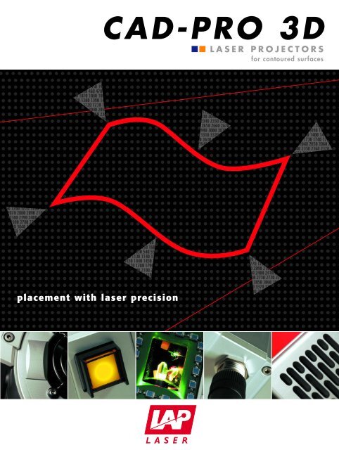
<strong>CAD</strong>-<strong>PRO</strong> <strong>3D</strong> LASER <strong>PRO</strong>JECTORS.HIGHLIGHTS.multicolor projection (green, red, yellow)easy-to-handle multiple projector solutionshighest precisionfast auto-calibrationcompact housing and lowest weightsealed housing area for projection componentsPRECISE, MULTICOLOR <strong>PRO</strong>JECTION.<strong>CAD</strong>-<strong>PRO</strong> <strong>3D</strong> laser projectors display outlines generated from <strong>CAD</strong> data on <strong>3D</strong> surfaces. Based oncalibration at reference points, scaling is 1:1.<strong>CAD</strong>-<strong>PRO</strong> <strong>3D</strong> can be equipped with one or two laser sources. You may choose green, red or bothsources for multicolored projection.FLEXIBLE, INTELLIGENT, SIMPLE.Large area projection is reached by connectingprojectors. They can be placed facing each otheror side by side. Distribution of data and loadbalancing works automated.In day to day use, automatic functions allow fastand easy calibration. Operating errors are avoidedto get highest precision and repeatability.Easy handling and installation is guaranteed by thecompact housing, low weight and an integratedswivel mount.
SOLUTIONS FOR YOUR COMPANY.THE OPERATING PRINCIPLE.<strong>CAD</strong>-<strong>PRO</strong> <strong>3D</strong>A laser beam deflected in x- and y-direction by two oscillating mirrorscontinuously traces the shape defined by the <strong>CAD</strong> data. The mirrorDSP (DigitalControlGalvanometerSignal Prozessor)drives (Galvanometers) are optimized for highest speed, accuracyGalvanometerMirrorMirrorand dynamic. Their movement is controlled by a digital trajectoryLaserprocessor. If the outline is traced more than approximately 20 timesper second, it appears solid to the eye.To achieve a projection exacting to scale, the projector softwareComputerrunning<strong>CAD</strong>auto-calibrates by scanning the position of target marks at measured<strong>PRO</strong>-SOFT <strong>3D</strong> workstationprojection of customercoordinates or machined reference points that are relative to thesoftwarework piece. This extremely fast, automatic procedure can be repeated any time without noticeable interruption of thework flow, allowing compliance with even the tightest dimensional tolerance and quality assurance standards.SYSTEM DESIGN.A typical laser templating solution consists of one or multiple laser projectors, a computer workstation, a mechanicalsupport for the projector, the customer's tool(s), and the related tool information in an electronic format.Typically, the projectors are located centrally above the tool, mounted to a roof truss or a stable support structure.Since the projectors must have a line-of-sight to a work surface, complex or large tool surfaces may require multipleprojectors, splitting their respective projection fields adjacent to, or partly or fully overlapping as needed.<strong>CAD</strong>-<strong>PRO</strong> projectors are controlled by a computer running <strong>PRO</strong>-SOFT<strong>3D</strong>, the associated <strong>3D</strong> projection software. The computer can be networkedwith the customer's <strong>CAD</strong> workstation. The <strong>PRO</strong> SOFT <strong>3D</strong> softwarestructures the complete working process: Reading of <strong>CAD</strong> data,processing of the contained templates in proper sequence, and controllingthe projector(s) accordingly.The basic interface hardware configuration consists of a PC cabinetwith IPC, LCD screen, keyboard, mouse or trackball, uninterruptible powersupply, interfaces, and any optional electronic components specified, including abig display showing the name of the actually projected template and a barcode readerfor identification of work pieces before and/or after they are placed.
OPTIMIZING YOUR <strong>PRO</strong>DUCTION.WORKING WITH LASER <strong>PRO</strong>JECTORS.To calibrate the projector to a new workpiece, minimally 4 reference targets must be appliedto the workpiece. After placing the customer's tool with reference targets in the working rangeof the projectors, the respective calibration target coordinates (calibration data) are loadedinto the software.Once calibrated, the projector is ready for use with the tool. The corresponding data file isloaded and the template for the first step in the production sequence is displayed. After itscompletion, the second template is activated; the corresponding operation executed, and soforth, until all production steps are completed.Changeover between templates can be done quickly by the supplied IR remote control or thecomputer keyboard. After finishing an item, the next item can be started or the tool can bechanged. It is possible to halt and resume the process at any time.SOFTWARE.The <strong>PRO</strong>-SOFT <strong>3D</strong> software provides userprivilege administration, flexible system configurationand calibration. Common <strong>CAD</strong>data can be used directly without the needof a postprocessor at the customer's site.The system calibration can be performed inthree ways:Manually: On the very first use of a productiontool. Semiautomatic: For knowntools, manual scanning of only the first targetsrequired. Automatic: For known toolon positions used before.The desktop displays templates graphically as well as in a structured list. Structured data (e.g.layer/sequence, groups, and plies) provide for a step by step working schedule.An integrated editor offers special projection functions like display of signal and warning icons,selection of projection color and integration of barcode information.Sensors, Guidelights, ProjectorsSystems & Solutions
TECHNICAL DATA.GENERAL DATA.Laser type, wavelength red: diode, 635 nmgreen: DPSS (solid state), 532 nmyellow: combined projection of red and greenAccuracy ± 0,5 mm up to distance of 4 m *Line width < 1 mm up to distance of 4 m *Max. projection angle 80°Laser powerLaser class5 mW2MEnclosure rating IP 54Ambient conditionsPower supplyConnectionDimensions (L x W x H)Weight0 - 40°C, 35% - 85% rel. humidity, non-condensing24 VDC, max. 1 ARS 485, Ethernet by interface300 x 110 x 110 mmca. 3 kg*projection angle < 60°, assuming correct calibration and focussing in projection color, surface perpendicular to laser beamSTANDARD SCOPE OF SUPPLY.Remote controlInstallation materialSwivel mountReference Targets(one version for all angles)ACCESSORIES AND OPTIONS.Cabinet equipped with industrial PC, monitor, UPS, TrackballMounting brackets and floor standsBig displaysSoftware plug ins: Barcode integration, log files, ...LAP has a great deal of experience with customer-specific solutions.Please inquire!Sensors, Guidelights, ProjectorsSystems & Solutions
LAP Laser LLC.Sales, Service7669 Wooster PikeCincinnati, OH 45227USAPhone +1 (513) 271-4529Fax +1 (513) 271-3821Email info-us@lap-laser.comLAP GmbHLaser ApplicationsHeadquarter: Production, Sales, ServiceZeppelinstr. 2321337 LueneburgGermanyPhone +49 (0)4131 9511-95Fax +49 (0)4131 9511-96Email info@lap-laser.comLAP Laser ApplicationsAsia Pacific Pte LtdSales, Service6 Battery Road, Unit #19-03Singapore 049909SingaporePhone +65 653 69990Fax +65 653 36697Email info-asia@lap-laser.comLAP Laser ApplicationsAsia Pacific Pte LtdShanghai Representative OfficeSales, Service36th Floor Jin Mao Tower88 Shi Ji Avenue, Shanghai 200120China••••••••••••••••••••••••••••••••••••••03/05 BE/SPECIALPhone +86 (21) 5047-8881Fax +86 (21) 5047-8887Email info-asia@lap-laser.comwww.LAP-LASER.comSensors, Guidelights, ProjectorsSystems & Solutions