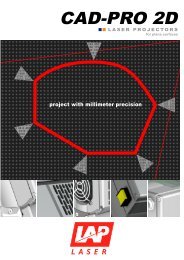
<strong>CAD</strong>-<strong>PRO</strong> <strong>3D</strong> LASER <strong>PRO</strong>JECTORS.HIGHLIGHTS.multicolor projection (green, red, yellow)easy-to-handle multiple projector solutionshighest precisionfast auto-calibrationcompact housing and lowest weightsealed housing area for projection componentsPRECISE, MULTICOLOR <strong>PRO</strong>JECTION.<strong>CAD</strong>-<strong>PRO</strong> <strong>3D</strong> laser projectors display outlines generated from <strong>CAD</strong> data on <strong>3D</strong> surfaces. Based oncalibration at reference points, scaling is 1:1.<strong>CAD</strong>-<strong>PRO</strong> <strong>3D</strong> can be equipped with one or two laser sources. You may choose green, red or bothsources for multicolored projection.FLEXIBLE, INTELLIGENT, SIMPLE.Large area projection is reached by connectingprojectors. They can be placed facing each otheror side by side. Distribution of data and loadbalancing works automated.In day to day use, automatic functions allow fastand easy calibration. Operating errors are avoidedto get highest precision and repeatability.Easy handling and installation is guaranteed by thecompact housing, low weight and an integratedswivel mount.
SOLUTIONS FOR YOUR COMPANY.THE OPERATING PRINCIPLE.<strong>CAD</strong>-<strong>PRO</strong> <strong>3D</strong>A laser beam deflected in x- and y-direction by two oscillating mirrorscontinuously traces the shape defined by the <strong>CAD</strong> data. The mirrorDSP (DigitalControlGalvanometerSignal Prozessor)drives (Galvanometers) are optimized for highest speed, accuracyGalvanometerMirrorMirrorand dynamic. Their movement is controlled by a digital trajectoryLaserprocessor. If the outline is traced more than approximately 20 timesper second, it appears solid to the eye.To achieve a projection exacting to scale, the projector softwareComputerrunning<strong>CAD</strong>auto-calibrates by scanning the position of target marks at measured<strong>PRO</strong>-SOFT <strong>3D</strong> workstationprojection of customercoordinates or machined reference points that are relative to thesoftwarework piece. This extremely fast, automatic procedure can be repeated any time without noticeable interruption of thework flow, allowing compliance with even the tightest dimensional tolerance and quality assurance standards.SYSTEM DESIGN.A typical laser templating solution consists of one or multiple laser projectors, a computer workstation, a mechanicalsupport for the projector, the customer's tool(s), and the related tool information in an electronic format.Typically, the projectors are located centrally above the tool, mounted to a roof truss or a stable support structure.Since the projectors must have a line-of-sight to a work surface, complex or large tool surfaces may require multipleprojectors, splitting their respective projection fields adjacent to, or partly or fully overlapping as needed.<strong>CAD</strong>-<strong>PRO</strong> projectors are controlled by a computer running <strong>PRO</strong>-SOFT<strong>3D</strong>, the associated <strong>3D</strong> projection software. The computer can be networkedwith the customer's <strong>CAD</strong> workstation. The <strong>PRO</strong> SOFT <strong>3D</strong> softwarestructures the complete working process: Reading of <strong>CAD</strong> data,processing of the contained templates in proper sequence, and controllingthe projector(s) accordingly.The basic interface hardware configuration consists of a PC cabinetwith IPC, LCD screen, keyboard, mouse or trackball, uninterruptible powersupply, interfaces, and any optional electronic components specified, including abig display showing the name of the actually projected template and a barcode readerfor identification of work pieces before and/or after they are placed.