Slowmo handleiding - RCtube.eu
Slowmo handleiding - RCtube.eu
Slowmo handleiding - RCtube.eu

You also want an ePaper? Increase the reach of your titles
YUMPU automatically turns print PDFs into web optimized ePapers that Google loves.
4 - <strong>Slowmo</strong><br />
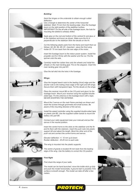
Building:<br />
Sand the hinges on the underside to obtain enough rudder<br />
deflection.<br />
Use a triangle to determine the center of the horizontal<br />
stabilizer. Mark 70 mm from the leading edge. Glue the fuselage<br />
boom on the right position of the stabilizer surface.<br />
IMPORTANT! On the aft side of the fuselage boom, the hole for<br />
mounting the tailskid is already drilled.<br />
Apply glue on the root and bottom of the vertical fin and glue ut<br />
to the stabilizer and boom as shown. Make sure the fin is<br />
perpendicular to the stabilizer Stick the decals on the fin.<br />
Cut the following plastic parts from the frame and insert them as<br />
follows: A8, B3, B4, B5, B1. Important : place the front wing<br />
holder B1 70 mm back from the rear edge of the motor.<br />
Insert the fuselage boom to the indoor power system. Install the<br />
propeller and fix it firmly with the washer and the nut. Put the<br />
spinner onto the axle.<br />
Carefully install the rubber tires onto the wheels and install the<br />
wheels on the main landing gear. Put on the stoppers. Insert the<br />
main landing gear into part B1.<br />
Glue the tail skid into the hole in the fuselage.<br />
Wings:<br />
Glue the longest beech rods to the leading (front) edge and the<br />
shorter rods to the trailing (rear) edge of the right and left wings.<br />
Secure them with transparent tape. Put the decals on the wings.<br />
Place the receiver mount B6 on the CG point and glue it to the<br />
fuselage boom. Mount your receiver using the supplied doublesided<br />
tape. Fix the antenna on the fuselage boom with a tape.<br />
NEVER SHORTEN THE ANTENNA<br />
Mount the 2 servos on the main frame precisely as shown and<br />
insert the screws through grommets and small screws. Be<br />
aware of the mounting direction of the servos.<br />
Install the speed controller using the supplied double-sided tape<br />
on plastic part B5. Use the supplied rubber bands to mount the<br />
battery into part B5.<br />
Connect your radio equipment (see your manual) and put the<br />
servos in the n<strong>eu</strong>tral position.<br />
Insert the control horns to the slots on the stabilizer and the fin<br />
and fix them with the retainers. Insert the push rods into plastic<br />
support A8 and adjust the length. Bend the other end of the<br />
push rod and connect the control horns and servos.<br />
Elevator deflection: +/- 10 mm up & down<br />
Rudder deflection: 20-25 mm to each side<br />
The wing is mounted into the plastic supports.<br />
The centre of gravity is located 55 mm back from the leading<br />
edge of the wing. Use the battery to correct the CG position.<br />
First flight<br />
First check the range of your radio.<br />
The model can be hand launched: move the trottle stick up fully<br />
and push the model horizontally. A ground start is possible if the<br />
surface is smooth enough. The model can take off after a few<br />
meters.