rotationslaser dw077 - Service - DeWALT
rotationslaser dw077 - Service - DeWALT
rotationslaser dw077 - Service - DeWALT

Create successful ePaper yourself
Turn your PDF publications into a flip-book with our unique Google optimized e-Paper software.
ENGLISH<br />
Battery cap (fig. C2)<br />
A protective cap is supplied to cover the contacts of<br />
a detached battery pack. Without the protective cap<br />
in place, loose metal objects could short circuit the<br />
contacts, causing a fire hazard and damaging the<br />
battery pack.<br />
• Take off the protective cap (11) before placing<br />
the battery pack (24) in the charger or tool.<br />
• Place the protective cap over the contacts<br />
immediately after removing the battery pack from<br />
the charger or tool.<br />
Equalization mode<br />
42<br />
Make sure the protective cap is in place<br />
before storing or carrying a detached<br />
battery pack.<br />
The equalization mode helps to<br />
maintain the optimum capacity of the<br />
battery pack. It is therefore<br />
recommended to use the equalization<br />
mode weekly or every 10 charge/<br />
discharge cycles.<br />
• Charge the battery pack as described above.<br />
• When the charging indicator stops blinking, leave<br />
the battery in the charger for approx. 4 hours.<br />
Hot Pack Delay<br />
When the charger detects a battery that is hot, it<br />
automatically starts a Hot Pack Delay, suspending<br />
charging until the battery has cooled. After the battery<br />
has cooled, the charger automatically switches to<br />
the pack charging mode. This feature ensures<br />
maximum battery life. The red indicator (14) blinks<br />
long, then short while in the Hot Pack Delay mode.<br />
Low battery indicator (fig C1)<br />
The tool has been equipped with a low battery<br />
indicator (15) located on the control panel. The low<br />
battery indicator is lit while the tool is switched on.<br />
It will blink to indicate that the battery pack needs to<br />
be recharged and the tool will automatically shut down.<br />
• Switch off the tool and take out the battery pack<br />
(11) to charge it as soon as the indicator blinks.<br />
The tool remains non-operational as long<br />
as a low battery pack is attached to it.<br />
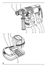
Battery type (fig. C3 & C4)<br />
The tool is suitable for battery packs with different<br />
voltages.<br />
• To fit battery packs of 18 volt, rotate the adapter<br />
plate (25) into position A.<br />
• To fit battery packs of 9.6, 12 or 14.4 volt,<br />
rotate the adapter plate (25) into position B.<br />
Refer to the table in the back for a selection of<br />
applicable battery packs.<br />
Setting up the tool (fig. D1 - D5)<br />
The tool facilitates various set-ups, making it useful<br />
for several applications.<br />
Floor set-up (fig. D1)<br />
• Place the tool on a relatively smooth and level<br />
surface.<br />
• Adjust the tool for a level or plumb application.<br />
Wall set-up (fig. D2 - D4)<br />
The tool has been equipped with a wall mount (11)<br />
for mounting to a wall track to aid in drop ceiling<br />
installation and other specialty leveling projects<br />
(fig. D2).<br />
• Fit the tool to the wall mount by inserting the<br />
threaded pin (23) into one of the receptacles in<br />
the tool and tightening the knob (15).<br />
• Turn the tool on its side with the wall mount<br />
clamp (13) in position for attachment to the wall<br />
track (fig. D3).<br />
• With the wall mount (11) facing the wall, turn the<br />
wall mount clamping lock (14) in the clockwise<br />
direction to open the clamp jaws.<br />
• Place the clamp jaws around the wall track and<br />
turn the wall mount clamping lock (14) in the<br />
anti-clockwise direction to close the clamp jaws<br />
shut on the track.<br />
• Ensure that the wall mount clamping lock (14) is<br />
securely locked.<br />
Before attaching the tool to a wall track<br />
ensure that the track is properly secured<br />
to the wall.<br />
• Alternatively, the tool can be hung on the wall<br />
using the mounting holes (27) in the wall mount<br />
(fig. D2).