MOBITRONIC M45R - Waeco
MOBITRONIC M45R - Waeco
MOBITRONIC M45R - Waeco
You also want an ePaper? Increase the reach of your titles
YUMPU automatically turns print PDFs into web optimized ePapers that Google loves.
_M45.book Seite 30 Freitag, 21. November 2008 11:05 11<br />
General information on the electrical connections<br />
<strong>M45R</strong><br />
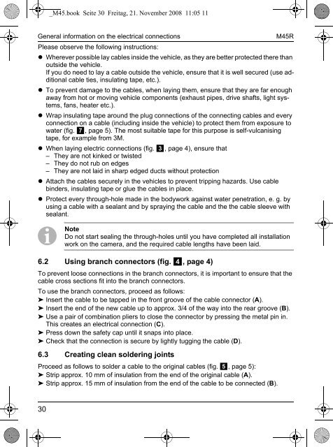
Please observe the following instructions:<br />
• Wherever possible lay cables inside the vehicle, as they are better protected there than<br />
outside the vehicle.<br />
If you do need to lay a cable outside the vehicle, ensure that it is well secured (use additional<br />
cable ties, insulating tape, etc.).<br />
• To prevent damage to the cables, when laying them, ensure that they are far enough<br />
away from hot or moving vehicle components (exhaust pipes, drive shafts, light systems,<br />
fans, heater etc.).<br />
• Wrap insulating tape around the plug connections of the connecting cables and every<br />
connection on a cable (including inside the vehicle) to protect them from exposure to<br />
water (fig. 7, page 5). The most suitable tape for this purpose is self-vulcanising<br />
tape, for example from 3M.<br />
• When laying electric connections (fig. 3, page 4), ensure that<br />
– They are not kinked or twisted<br />
– They do not rub on edges<br />
– They are not laid in sharp edged ducts without protection<br />
• Attach the cables securely in the vehicles to prevent tripping hazards. Use cable<br />
binders, insulating tape or glue the cables in place.<br />
• Protect every through-hole made in the bodywork against water penetration, e. g. by<br />
using a cable with a sealant and by spraying the cable and the the cable sleeve with<br />
sealant.<br />
I Note<br />
Do not start sealing the through-holes until you have completed all installation<br />
work on the camera, and the required cable lengths have been laid.<br />
6.2 Using branch connectors (fig. 4, page 4)<br />
To prevent loose connections in the branch connectors, it is important to ensure that the<br />
cable cross sections fit into the branch connectors.<br />
To use the branch connectors, proceed as follows:<br />
➤ Insert the cable to be tapped in the front groove of the cable connector (A).<br />
➤ Insert the end of the new cable up to approx. 3/4 of the way into the rear groove (B).<br />
➤ Use a pair of combination pliers to close the connector by pressing the metal pin in.<br />
This creates an electrical connection (C).<br />
➤ Press down the safety cap until it snaps into place.<br />
➤ Check that the connection is secure by lightly tugging the cable (D).<br />
6.3 Creating clean soldering joints<br />
Proceed as follows to solder a cable to the original cables (fig. 5, page 5):<br />
➤ Strip approx. 10 mm of insulation from the end of the original cable (A).<br />
➤ Strip approx. 15 mm of insulation from the end of the cable to be connected (B).<br />
30


