Instrucciones de montaje - Waeco
Instrucciones de montaje - Waeco
Instrucciones de montaje - Waeco

Create successful ePaper yourself
Turn your PDF publications into a flip-book with our unique Google optimized e-Paper software.
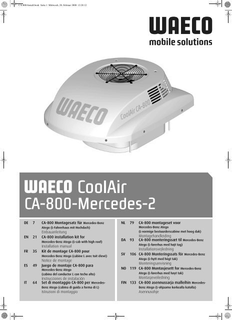
CA-800-Install.book Seite 1 Mittwoch, 20. Februar 2008 12:28 12CA-800-Merce<strong>de</strong>s-2DE 7 CA-800 Montagesatz für Merce<strong>de</strong>s-BenzAtego (L-Fahrerhaus mit Hochdach)EinbauanleitungEN 21 CA-800 installation kit forMerce<strong>de</strong>s-Benz Atego (L-cab with high roof)Installation manualFR 35 Kit <strong>de</strong> montage CA-800 pourMerce<strong>de</strong>s-Benz Atego (cabine L avec toit élevé)Notice <strong>de</strong> montageES 49 Juego <strong>de</strong> <strong>montaje</strong> CA-800 paraMerce<strong>de</strong>s-Benz Atego(cabina <strong>de</strong>l conductor L con techo alto)<strong>Instrucciones</strong> <strong>de</strong> instalaciónIT 64 Set di montaggio CA-800 per Merce<strong>de</strong>s-Benz Atego (cabina di guida a forma di L)Istruzioni di montaggioNL 79 CA-800 montageset voorMerce<strong>de</strong>s-Benz Atego(L-vormige bestuur<strong>de</strong>rscabine met hoog dak)MontagehandleidingDA 93 CA-800 monteringssæt til Merce<strong>de</strong>s-BenzAtego (L-førerhus med højt tag)InstallationsvejledningSV 106 CA-800 Monteringssats för Merce<strong>de</strong>s-BenzAtego (L-hytt med högt tak)MonteringsanvisningNO 119 CA-800 Montasjesett for Merce<strong>de</strong>s-BenzAtego (L-førerhus med høyt tak)MontasjeveiledningFIN 133 CA-800 asennussarja malleihin Merce<strong>de</strong>s-Benz Atego (L-ohjaamo korkealla katolla)Asennusohje
CA-800-Install.book Seite 2 Mittwoch, 20. Februar 2008 12:28 12DFor<strong>de</strong>rn Sie weitere Informationen zur umfangreichen Produktpalette aus <strong>de</strong>m HauseWAECO an. Bestellen Sie einfach unsere Kataloge kostenlos und unverbindlichunter <strong>de</strong>r Internetadresse: www.waeco.<strong>de</strong>GBWe will be happy to provi<strong>de</strong> you with further information about WAECO products.Please or<strong>de</strong>r our free catalogue with no obligation to buy on our homepage:www.waeco.comFDeman<strong>de</strong>z d’autres informations relatives à la large gamme <strong>de</strong> produits <strong>de</strong> lamaison WAECO. Comman<strong>de</strong>z tout simplement notre catalogue gratuitement etsans engagement à l’adresse internet suivante : www.waeco.comESolicite más información sobre la amplia gama <strong>de</strong> productos <strong>de</strong> la empresa WAE-CO. Solicite simplemente nuestros catálogos <strong>de</strong> forma gratuita y sin compromiso enla dirección <strong>de</strong> Internet: www.waeco.comIPer ottenere maggiori informazioni sull’ampia gamma di prodotti WAECO è possibileordinare una copia gratuita e non vincolante <strong>de</strong>l nostro Catalogo all’indirizzo Internet:www.waeco.comNLMaak kennis met het omvangrijke productscala van <strong>de</strong> firma WAECO. Bestel onzecatalogus gratis en vrijblijvend on<strong>de</strong>r het internetadres: www.waeco.comDKBestil y<strong>de</strong>rligere information om <strong>de</strong>t omfatten<strong>de</strong> produktudvalg fra WAECO.Bestil vores katalog gratis og uforpligten<strong>de</strong> på internetadressen: www.waeco.comSInhämta mer information om <strong>de</strong>n omfattan<strong>de</strong> produktpaletten från WAECO:Beställ våra kataloger gratis och utan förpliktelser un<strong>de</strong>r vår Internetadress:www.waeco.comNBe om mer informasjon om <strong>de</strong>t rikholdige produktutvalget fra WAECO. Bestill vårkatalog gratis uforbindtlig på Internettadressen: www.waeco.comFINPyytäkää lisää tietoja WAECOn kattavista tuotevalikoimista. Tilatkaa tuotekuvastommemaksutta ja sitoumuksetta internet-osoitteesta: www.waeco.com
CA-800-Install.book Seite 3 Mittwoch, 20. Februar 2008 12:28 12CoolAir1401 2912092131234563
CA-800-Install.book Seite 4 Mittwoch, 20. Februar 2008 12:28 12CoolAir45123454
CA-800-Install.book Seite 5 Mittwoch, 20. Februar 2008 12:28 126CoolAir1781 2 3 4 5 6 75
CA-800-Install.book Seite 6 Mittwoch, 20. Februar 2008 12:28 12CoolAir8bl br gl gr ro sw wDE Blau Braun Gelb Grün Rot Schwarz WeissEN Blue Brown Yellow Green Red Black WhiteES Azul Marrón Amarillo Ver<strong>de</strong> Rojo Negro BlancoFR Bleu Marron Jaune Vert Rouge Noir BlancIT Blu Marrone Giallo Ver<strong>de</strong> Rosso Nero BiancoNL Blauw Bruin Geel Groen Rood Zwart WitDA Blå Brun Gul Grøn Rød Sort HvidSV Blå Brun Gul Grön Röd Svart VitNO Blå Brun Gul Grønn Rød Svart HvitFI Sininen Ruskea Keltainen Vihreä Punainen Musta Valkoinen6
CA-800-Install.book Seite 7 Mittwoch, 20. Februar 2008 12:28 12CoolAirInhaltsverzeichnisSicherheitshinweise1 Sicherheitshinweise . . . . . . . . . . . . . . . . . . . . . . . . . . . . . . . . . . . . . . . . . . . . . . . . . . . 71.1 Umgang mit <strong>de</strong>m Gerät. . . . . . . . . . . . . . . . . . . . . . . . . . . . . . . . . . . . . . . . . . . . 81.1.1 Umgang mit elektrischen Leitungen . . . . . . . . . . . . . . . . . . . . . . . . . . . . . . . . . . . . 82 Handbuchkonventionen . . . . . . . . . . . . . . . . . . . . . . . . . . . . . . . . . . . . . . . . . . . . . . . . 92.1 Allgemeine Informationen zur Einbauanleitung . . . . . . . . . . . . . . . . . . . . . . . . . 92.2 Zielgruppe . . . . . . . . . . . . . . . . . . . . . . . . . . . . . . . . . . . . . . . . . . . . . . . . . . . . . . 92.3 Symbole und Formate. . . . . . . . . . . . . . . . . . . . . . . . . . . . . . . . . . . . . . . . . . . . . 93 Bestimmungsgemäßer Gebrauch . . . . . . . . . . . . . . . . . . . . . . . . . . . . . . . . . . . . . . . 104 Lieferumfang . . . . . . . . . . . . . . . . . . . . . . . . . . . . . . . . . . . . . . . . . . . . . . . . . . . . . . . . 115 Zubehör . . . . . . . . . . . . . . . . . . . . . . . . . . . . . . . . . . . . . . . . . . . . . . . . . . . . . . . . . . . .116 Installation . . . . . . . . . . . . . . . . . . . . . . . . . . . . . . . . . . . . . . . . . . . . . . . . . . . . . . . . . .116.1 Hinweise zur Installation . . . . . . . . . . . . . . . . . . . . . . . . . . . . . . . . . . . . . . . . . . 116.2 Installationschritte . . . . . . . . . . . . . . . . . . . . . . . . . . . . . . . . . . . . . . . . . . . . . . . 136.2.1 Dachluke ausbauen. . . . . . . . . . . . . . . . . . . . . . . . . . . . . . . . . . . . . . . . . . . . . . . . 136.2.2 Anlage vorbereiten . . . . . . . . . . . . . . . . . . . . . . . . . . . . . . . . . . . . . . . . . . . . . . . . 136.2.3 Ausgleichsplatte befestigen. . . . . . . . . . . . . . . . . . . . . . . . . . . . . . . . . . . . . . . . . . 146.2.4 Dichtung zum Fahrerhausdach anbringen . . . . . . . . . . . . . . . . . . . . . . . . . . . . . . 146.2.5 Anlage in Dachluke einbauen . . . . . . . . . . . . . . . . . . . . . . . . . . . . . . . . . . . . . . . . 146.2.6 Versorgungsleitungen verlegen. . . . . . . . . . . . . . . . . . . . . . . . . . . . . . . . . . . . . . . 156.2.7 Ab<strong>de</strong>ckrahmen befestigen. . . . . . . . . . . . . . . . . . . . . . . . . . . . . . . . . . . . . . . . . . . 166.3 Konfiguration <strong>de</strong>r Anlagen-Software . . . . . . . . . . . . . . . . . . . . . . . . . . . . . . . . . 166.3.1 Starten und Been<strong>de</strong>n <strong>de</strong>s Konfigurationsmodus. . . . . . . . . . . . . . . . . . . . . . . . . . 176.3.2 Menüebene 1: Vorgabe Temperatur-Sollwert . . . . . . . . . . . . . . . . . . . . . . . . . . . . 176.3.3 Menüebene 2: Unterspannungsabschaltung. . . . . . . . . . . . . . . . . . . . . . . . . . . . . 186.3.4 Menüebene 3: Vorgabe Betriebsmodus . . . . . . . . . . . . . . . . . . . . . . . . . . . . . . . . 196.3.5 Menüebene 4: Werkseinstellung . . . . . . . . . . . . . . . . . . . . . . . . . . . . . . . . . . . . . . 197 Technische Daten . . . . . . . . . . . . . . . . . . . . . . . . . . . . . . . . . . . . . . . . . . . . . . . . . . . . 201 SicherheitshinweiseEs ist zwingend notwendig, <strong>de</strong>n gesamten Inhalt <strong>de</strong>s Handbuches aufmerksamzu lesen.Nur wenn <strong>de</strong>n Anleitungen Folge geleistet wird, können Zuverlässigkeit<strong>de</strong>r Dachklimaanlage und Schutz vor Personen- o<strong>de</strong>r Sachschä<strong>de</strong>n gewährleistetwer<strong>de</strong>n.Der Hersteller übernimmt keine Haftung für Schä<strong>de</strong>n aufgrund folgen<strong>de</strong>rPunkte:• Montagefehler,• Beschädigungen am System durch mechanische Einflüsse und Überspannungen,• Verän<strong>de</strong>rungen an <strong>de</strong>r Dachklimaanlage ohne ausdrücklicheGenehmigung <strong>de</strong>s Herstellers,• Verwendung für an<strong>de</strong>re als die in <strong>de</strong>r Einbauanleitung beschriebenenZwecke.7
CA-800-Install.book Seite 8 Mittwoch, 20. Februar 2008 12:28 12Sicherheitshinweise1.1 Umgang mit <strong>de</strong>m Gerät8CoolAir• Benutzen Sie die Dachklimaanlage nur für <strong>de</strong>n vom Herstellerangegebenen Verwendungszweck und führen Sie keine Än<strong>de</strong>rungeno<strong>de</strong>r Umbauten am Gerät durch!• Betreiben Sie die Dachklimaanlage nur, wenn das Gehäuse und dieLeitungen unbeschädigt sind!• Die Dachklimaanlage muss so sicher installiert wer<strong>de</strong>n, dass diese nichtumstürzen o<strong>de</strong>r herabfallen kann!• Die Installation, Wartung und etwaige Reparatur dürfen nur durch einenFachbetrieb erfolgen, <strong>de</strong>r mit <strong>de</strong>n damit verbun<strong>de</strong>nen Gefahren bzw.einschlägigen Vorschriften vertraut ist!• Setzen Sie die Dachklimaanlage nicht in <strong>de</strong>r Nähe von entflammbarenFlüssigkeiten o<strong>de</strong>r in geschlossenen Räumen ein.• Greifen Sie nicht in Lüftungsgitter o<strong>de</strong>r Lüftungsdüsen, und stecken Siekeine Fremdgegenstän<strong>de</strong> in die Anlage.• Im Falle von Feuer lösen Sie nicht <strong>de</strong>n oberen Deckel <strong>de</strong>rDachklimaanlage, son<strong>de</strong>rn verwen<strong>de</strong>n Sie zugelassene Löschmittel.Verwen<strong>de</strong>n Sie kein Wasser zum Löschen.• Schalten Sie die Dachklimaanlage aus, bevor Sie automatische Waschvorrichtungen(Waschanlagen etc.) zur Reinigung <strong>de</strong>s Fahrzeugsnutzen!• Bitte informieren Sie sich bei Ihrem Fahrzeughersteller, ob aufgrund<strong>de</strong>s Aufbaues <strong>de</strong>r Dachklimaanlage (Aufbauhöhe 209 mm) eineÄn<strong>de</strong>rung <strong>de</strong>s Eintrags <strong>de</strong>r Fahrzeughöhe in ihren Fahrzeugpapierennotwendig ist.• Lösen Sie bei Arbeiten am Gerät alle Verbindungen zur Batterie!• Beachten Sie, dass Sie vor <strong>de</strong>m Umklappen <strong>de</strong>s Führerhauses o<strong>de</strong>r zuWartungszwecken das restliche Kon<strong>de</strong>nswasser manuell aus <strong>de</strong>r Anlageablassen (siehe Kapitel „Kon<strong>de</strong>nsat absaugen“ in <strong>de</strong>r BedienungsanleitungCoolAir CA-800).1.1.1 Umgang mit elektrischen Leitungen• Müssen Leitungen durch scharfkantige Wän<strong>de</strong> geführt wer<strong>de</strong>n, soverwen<strong>de</strong>n Sie Leerrohre bzw. Leitungsdurchführungen!• Verlegen Sie keine losen o<strong>de</strong>r scharf abgeknickten Leitungen anelektrisch leiten<strong>de</strong>n Materialien (Metall)!• Ziehen Sie nicht an Leitungen!• Befestigen und verlegen Sie Leitungen so, dass keine Stolpergefahrentsteht und eine Beschädigung <strong>de</strong>s Kabels ausgeschlossen ist.• Der elektrische Anschluss darf nur von einem Fachbetrieb durchgeführtwer<strong>de</strong>n.• Sichern Sie <strong>de</strong>n Anschluss ans Netz im Fahrzeug mit min<strong>de</strong>stens25 Ampere ab.• Verlegen Sie niemals die Spannungsversorgungsleitung (Batteriekabel)in räumlicher Nähe zu Signal- o<strong>de</strong>r Steuerleitungen.
CA-800-Install.book Seite 9 Mittwoch, 20. Februar 2008 12:28 12CoolAir2 HandbuchkonventionenHandbuchkonventionen2.1 Allgemeine Informationen zur EinbauanleitungDiese Einbauanleitung enthält die wesentlichen Informationen und Anleitungenfür die Installation <strong>de</strong>r Dachklimaanlage. Die enthaltenen Informationenrichten sich an <strong>de</strong>n Installationsbetrieb <strong>de</strong>r Dachklimaanlage.Folgen<strong>de</strong> Hinweise helfen Ihnen bei <strong>de</strong>r korrekten Anwendung <strong>de</strong>rEinbauanleitung:• Die Einbauanleitung ist Teil <strong>de</strong>s Lieferumfangs und ist sorgfältigaufzubewahren.• Die Einbauanleitung gibt Ihnen wichtige Hinweise für die Montage unddient gleichzeitig in Reparaturfällen als Nachschlagewerk.• Bei Nichtbeachtung dieser Einbauanleitung haftet <strong>de</strong>r Hersteller nicht.Jegliche Ansprüche sind für diesen Fall ausgeschlossen.Die Bedienungsanleitung zur CoolAir CA-800 fin<strong>de</strong>n Sie im Lieferumfang<strong>de</strong>r Dachklimaanlage.2.2 ZielgruppeInstallations- und Konfigurationsinformationen in dieser Anleitung richtensich an Facharbeiter in Installationsbetrieben die mit <strong>de</strong>n anzuwen<strong>de</strong>n<strong>de</strong>nRichtlinien und Sicherheitsvorkehrungen beim Einbau von Lkw-Zubehörteilenvertraut sind.2.3 Symbole und FormateIn dieser Dokumentation wer<strong>de</strong>n Ihnen bestimmte Symbole und Formatebegegnen. Diese haben folgen<strong>de</strong> Be<strong>de</strong>utung:Format Be<strong>de</strong>utung BeispielFett Wichtige Informationen im Schalter (3) auf SymbolText, die nicht missverstan<strong>de</strong>n KÜHLEN stellen.wer<strong>de</strong>n dürfen➤ Handlungsanleiten<strong>de</strong> Texte ➤ Legen Sie die Dachklimaanlagemit <strong>de</strong>m Gehäusenach unten auf eineArbeitsfläche.✓Ergebnisse eines Handlungsschrittes✓ Die Anlage ist nun betriebsbereit.9
CA-800-Install.book Seite 10 Mittwoch, 20. Februar 2008 12:28 12Bestimmungsgemäßer GebrauchCoolAirHinweis auf:• mögliche Verletzungsrisiken für <strong>de</strong>n Installateur o<strong>de</strong>r <strong>de</strong>n Anwen<strong>de</strong>rund• mögliche Gerätebeschädigung.Zeigt eine mögliche Gefahrensituation an, die während <strong>de</strong>r Montage bzw.im Betrieb <strong>de</strong>s Produkts entstehen könnte und Schä<strong>de</strong>n am Gerät bzw.eine Umweltschädigung o<strong>de</strong>r wirtschaftliche Schä<strong>de</strong>n verursachen kann.Beson<strong>de</strong>re Informationen zum Umgang mit <strong>de</strong>m Produkt.3 Bestimmungsgemäßer GebrauchDer Montagesatz (Artikelnummer: CA-EK-MB2) ermöglicht <strong>de</strong>n Einbaueiner Dachklimaanlage CoolAir CA-800 (Artikelnummer: CA-0800-DC) ineine werkseitig vorhan<strong>de</strong>ne Dachlukenöffnung (Lüftungsluke) eines Merce<strong>de</strong>s-BenzAtego (L-Fahrerhaus mit Hochdach).Die Dachklimaanlage CA-800 ist nicht für die Installation in Baumaschinen,Landmaschinen o<strong>de</strong>r ähnlichen Arbeitsgeräten geeignet. Beizu starker Vibrationseinwirkung ist eine ordnungsgemäße Funktion nichtgewährleistet.Die Dachklimaanlage CA-800 ist für eine Umgebungstemperatur nichtüber 43 °C im Kühlbetrieb ausgelegt.Der Betrieb <strong>de</strong>r Dachklimaanlage CA-800 mit Spannungswerten, die von<strong>de</strong>n angegebenen Werten abweichen, führt zur Beschädigung <strong>de</strong>s Gerätes.10
CA-800-Install.book Seite 11 Mittwoch, 20. Februar 2008 12:28 12CoolAir4 LieferumfangCA-800 Montagesatz für Merce<strong>de</strong>s-Benz Atego(L-Fahrerhaus mit Hochdach)Art. Nr. CA-EK-MB2LieferumfangTeilebezeichnung Menge Art.-Nr.Ab<strong>de</strong>ckrahmen 1 44430002342,5 m Dichtungsband (Profil: 25 x 25 mm) 1 –2 m Dichtungsband (Profil: 25 x 10 mm) 1 –Ausgleichsplatte 1 4442500347Distanzhülse L=3 mm 4 4443900170Selbstsichern<strong>de</strong> Mutter M8 8 –Unterlegscheibe M8 8 –Distanzhülse L=15 mm 8 4443900211Einbauanleitung 1 44451003095 ZubehörTeilebezeichnungDachklimaanlage CoolAir CA-800Schutzhaube für Dachklimaanlage CoolAir CA-800Art.-Nr.CA-0800-DCCA-SH16 InstallationDie Installation <strong>de</strong>r Dachklimaanlage darf ausschließlich von entsprechendausgebil<strong>de</strong>ten Fachbetrieben durchgeführt wer<strong>de</strong>n. Die nachfolgen<strong>de</strong>nInformationen richten sich an Fachkräfte, die mit <strong>de</strong>n anzuwen<strong>de</strong>n<strong>de</strong>nRichtlinien und Sicherheitsvorkehrungen vertraut sind.6.1 Hinweise zur InstallationVor <strong>de</strong>r Installation <strong>de</strong>r Dachklimaanlage muss diese Einbauanleitung vollständiggelesen wer<strong>de</strong>n.Folgen<strong>de</strong> Tipps und Hinweise müssen bei <strong>de</strong>r Installation <strong>de</strong>r Dachklimaanlagebeachtet wer<strong>de</strong>n:Stellen Sie vor Arbeiten an elektrisch betriebenen Komponenten sicher,dass keine Spannung mehr anliegt!11
CA-800-Install.book Seite 12 Mittwoch, 20. Februar 2008 12:28 12InstallationCoolAir• Grundsätzlich ist vor Installation <strong>de</strong>r Dachklimaanlage zu überprüfen, obdurch <strong>de</strong>n Einbau <strong>de</strong>r Dachklimaanlage ggf. Fahrzeugkomponentenbeschädigt o<strong>de</strong>r in ihrer Funktion beeinträchtigt wer<strong>de</strong>n könnten.Anhand <strong>de</strong>r Abb. 1 auf Seite 3 können Sie die Dimensionen <strong>de</strong>reingebauten Anlage prüfen. Die gestrichelte Linie bezieht sich hierbeiauf die Mitte <strong>de</strong>r Dachlukenöffnung.• Vor Einbau müssen Sie – über <strong>de</strong>n Fahrzeughersteller – klären, ob <strong>de</strong>rAufbau für das statische Gewicht und die Belastungen durch dieKlimaanlage bei in Bewegung befindlichem Fahrzeug ausgelegt ist. DerHersteller <strong>de</strong>r Dachklimaanlage übernimmt keinerlei Haftung.• Die Dachneigung <strong>de</strong>r Montagefläche darf in Fahrtrichtung nicht mehrals 8° und nach hinten nicht mehr als 0° betragen.• Die mitgelieferten Montageteile dürfen beim Einbau nicht eigenmächtigmodifiziert wer<strong>de</strong>n.• Wir empfehlen die Schnittkante <strong>de</strong>r Ausgleichsplatte mitKorrosionsschutzmittel zu versehen, um möglichem Rostansatz(optischer Mangel) vorzubeugen.• Beachten Sie auch <strong>de</strong>n Anschlussplan zur Dachklimaanlage:Nr in Abb. 8Bezeichnungauf Seite 61 Bedienfolie2 Flachbandkabel 12 + 2 polig3 Raumtemperaturfühler4 Niveaugeber5 Masse/Erdung6 Klickson (Kompressor)7 Kompressor8 Wasserpumpe9 Zusatzlüfter10 Hauptlüfter11 Masse/Erdung12 Fernbedienungsempfänger13 Sicherung 125 mAEine falsche Installation <strong>de</strong>r Klimaanlage kann zu irreparablen Schä<strong>de</strong>nam Gerät führen und die Sicherheit <strong>de</strong>s Benutzers beeinträchtigen.Wenn die Dachklimaanlage nicht gemäß dieser Einbauanleitung installiertwird, übernimmt <strong>de</strong>r Hersteller keinerlei Haftung. Nicht für Betriebsstörungenund für die Sicherheit <strong>de</strong>r Dachklimaanlage, insbeson<strong>de</strong>re nicht fürPersonen- und/o<strong>de</strong>r Sachschä<strong>de</strong>n.12
CA-800-Install.book Seite 13 Mittwoch, 20. Februar 2008 12:28 12CoolAirInstallationNach <strong>de</strong>r Installation <strong>de</strong>r Anlage müssen die vorgegebenen Parameter <strong>de</strong>rAnlagen-Software überprüft wer<strong>de</strong>n (siehe Kapitel „Konfiguration <strong>de</strong>r Anlagen-Software”auf Seite 16).6.2 InstallationschritteDer Hersteller übernimmt ausschließlich Haftung für im Lieferumfang enthalteneTeile. Beim Einbau <strong>de</strong>r Anlage zusammen mit produktfrem<strong>de</strong>nTeilen entfällt die Gewährleistungsgarantie.Bevor Sie das Fahrzeugdach besteigen, prüfen Sie, ob dieses für Personenbegehbar ist. Zulässige Dachlasten können Sie beim Fahrzeugherstellererfragen.6.2.1 Dachluke ausbauen➤➤➤Entfernen Sie alle Schrauben und Befestigungen <strong>de</strong>r vorhan<strong>de</strong>nenDachluke.Nehmen Sie die Dachluke heraus.Entfernen Sie das Dichtungsmaterial rund um die Öffnung, sodass <strong>de</strong>rUntergrund sauber und fettfrei ist.Entsorgen Sie sämtliches Abfallmaterial, Leim, Silikon und Dichtungen getrennt.Beachten Sie dabei die Entsorgungsrichtlinien.6.2.2 Anlage vorbereitenSichern Sie die Anlage bei <strong>de</strong>n Vorbereitungen auf <strong>de</strong>r Arbeitsfläche vor<strong>de</strong>m Hinabfallen. Achten Sie auf eine ebene und saubere Unterlage, damitdie Anlage nicht beschädigt wird.➤➤Legen Sie die Dachklimaanlage mit <strong>de</strong>m Gehäuse nach unten auf eineArbeitsfläche.Entfernen Sie die vier M8 Muttern, Fe<strong>de</strong>rringe und Unterlegscheibenvon <strong>de</strong>n vier Gewin<strong>de</strong>bolzen (siehe Abb. 2 auf Seite 3, Pos. 1).➤ Stecken Sie die vier Distanzhülsen L= 3 mm (siehe Abb. 3 auf Seite 3,Pos. 4) auf die vier Gewin<strong>de</strong>bolzen (siehe Abb. 3 auf Seite 3, Pos. 6).13
CA-800-Install.book Seite 14 Mittwoch, 20. Februar 2008 12:28 12InstallationCoolAir➤ Kleben Sie das 2 m lange Dichtungsband (25 x 10 mm, siehe Abb. 3auf Seite 3, Pos. 5) in die vorhan<strong>de</strong>ne Vertiefung auf die Anlage. VersehenSie die Stoßkante und die Oberkante <strong>de</strong>s Dichtungbands mit einemplastischen nicht aushärten<strong>de</strong>n Butyldichtstoff (z.B.SikaLastomer-710).6.2.3 Ausgleichsplatte befestigen➤Setzen Sie die Ausgleichsplatte auf die Anlage. Stecken Sie hierzu dievier Gewin<strong>de</strong>bolzen durch die vier Langlöcher in <strong>de</strong>r Ausgleichsplatte.Die Ausgleichsplatte passt die Dachklimaanlage auf die fahrzeugspezifischenGegebenheiten an.➤Schrauben Sie je eine Mutter M8 + Fe<strong>de</strong>rring + Unterlegscheibe(siehe Abb. 3 auf Seite 3, Pos. 1-3) auf die vier Gewin<strong>de</strong>bolzen.Drehen Sie die Muttern mit <strong>de</strong>r Hand an. Das Festziehen <strong>de</strong>r Mutternerfolgt zu einem späteren Zeitpunkt.6.2.4 Dichtung zum Fahrerhausdach anbringenStellen Sie sicher, dass die Klebefläche für die Dichtung zwischen Ausgleichsplatteund Fahrerhausdach sauber (frei von Staub, Öl usw.) ist.➤➤Kleben Sie das 2,5 m lange Dichtungsband (25 x 25 mm) <strong>de</strong>r Kontur<strong>de</strong>r Dachlukenöffnung folgend auf das Dach <strong>de</strong>s Fahrerhauses (sieheAbb. 4 auf Seite 4).Versehen Sie die Stoßkante und die Oberkante <strong>de</strong>s Dichtungsbandsmit einem plastischen nicht aushärten<strong>de</strong>n Butyldichtstoff (z.B. Sika-Lastomer-710).6.2.5 Anlage in Dachluke einbauen➤Setzen Sie die Anlage zentrisch und in Fahrtrichtung (siehe Abb. 1 aufSeite 3) auf die Dachlukenöffnung. Die acht Befestigungsbolzen <strong>de</strong>rAusgleichsplatte müssen hierbei in die werkseitig um die Dachlukenöffnungpositionierten Bohrungen gesteckt wer<strong>de</strong>n.Es ist eine perfekte Zentrierung <strong>de</strong>r Dachklimaanlage sicherzustellen.Nach <strong>de</strong>m Aufsetzen auf das Fahrzeugdach muss die Dichtung umlaufendauf <strong>de</strong>m Fahrzeugdach anliegen.Nur so ist eine sichere Abdichtung möglich!➤Schrauben Sie je eine selbstsichern<strong>de</strong> Mutter M8 + Unterlegscheibe(siehe Abb. 5 auf Seite 4, Pos. 2 und 1) auf die acht Befestigungsbolzen.Ziehen Sie zur Befestigung <strong>de</strong>r Anlage die Muttern mit einemDrehmoment von 10 Nm an.14
CA-800-Install.book Seite 15 Mittwoch, 20. Februar 2008 12:28 12CoolAirInstallation➤ Ziehen Sie die vier Muttern M8 auf <strong>de</strong>n Gewin<strong>de</strong>bolzen (siehe Abb. 3auf Seite 3, Pos. 6) nochmals handfest nach.6.2.6 Versorgungsleitungen verlegenVor Arbeiten an elektrisch betriebenen Komponenten ist sicherzustellen,dass keine Spannung anliegt!Die Anlage verfügt serienmäßig über ein 3,5 m langes 4 mm 2 Kabel. Solltenlängere Kabellängen benötigt wer<strong>de</strong>n, muss durch eine autorisierteFachwerkstatt <strong>de</strong>r Kabelquerschnitt erhöht wer<strong>de</strong>n:Schnei<strong>de</strong>n Sie das 4 mm 2 Kabel so nah wie möglich an <strong>de</strong>r Anlage (max.0,5 m) ab und stellen Sie anschließend eine fachgerechte Verbindung aufeinen größeren Kabelquerschnitt her.Der Hersteller empfiehlt ab 3,5 m bis 6 m Länge einen Querschnitt von 6mm 2 .Sichern Sie <strong>de</strong>n Anschluss ans Netz im Fahrzeug mit min<strong>de</strong>stens25 Ampere ab.Die Dachklimaanlage muss an eine Batterie angeschlossen wer<strong>de</strong>n, die in<strong>de</strong>r Lage ist, <strong>de</strong>n benötigten Strom (siehe Kapitel „Technische Daten” aufSeite 20) zu liefern.Sie können die Anlage sowohl über <strong>de</strong>n Hauptverteiler <strong>de</strong>s Lkw als auchdirekt mit <strong>de</strong>r Batterie verbin<strong>de</strong>n. Hierbei sollte <strong>de</strong>r Anschluss über <strong>de</strong>nHauptverteiler bevorzugt wer<strong>de</strong>n. Fragen Sie zu <strong>de</strong>n Spezifikationen <strong>de</strong>sHauptverteilers Ihren Fahrzeughersteller.➤➤➤Verlegen Sie die Versorgungsleitung und schließen Sie diese fahrzeugseitigan (rote Leitung an Plus und schwarze Leitung an Minus).Stecken Sie <strong>de</strong>n Stecker <strong>de</strong>r Versorgungsleitung in die Buchse an <strong>de</strong>rDachklimaanlage.Sichern Sie die Versorgungsleitung mit einem Kabelbin<strong>de</strong>r gegen zuhohe Schwingungen am Anschlussstecker (siehe Abb. 6 auf Seite 5,Pos. 1).15
CA-800-Install.book Seite 16 Mittwoch, 20. Februar 2008 12:28 12Installation6.2.7 Ab<strong>de</strong>ckrahmen befestigenCoolAirZiehen Sie die Schrauben nur vorsichtig an, damit <strong>de</strong>r Ab<strong>de</strong>ckrahmennicht beschädigt wird.➤ Befestigen Sie <strong>de</strong>n Ab<strong>de</strong>ckrahmen (siehe Abb. 5 auf Seite 4, Pos. 4)in Verbindung mit <strong>de</strong>n Distanzhülsen (Pos. 3) und <strong>de</strong>n original Schrauben(Pos. 5) am Fahrerhausdach. Die Distanzhülsen dienen hierbeials Abstandshalter für <strong>de</strong>n Ab<strong>de</strong>ckrahmen zum Fahrerhausdach.6.3 Konfiguration <strong>de</strong>r Anlagen-SoftwareVor <strong>de</strong>r ersten Inbetriebnahme <strong>de</strong>r Anlage muss die Steuerung auf dieunterschiedlichen Einbaugegebenheiten angepasst wer<strong>de</strong>n. DieseAnpassung muss von <strong>de</strong>m Einbauer vorgenommen wer<strong>de</strong>n.In einem Konfigurationsmodus wer<strong>de</strong>n folgen<strong>de</strong> Parameter <strong>de</strong>r Anlagen-Software über das Bedienpanel (siehe Abb. 7 auf Seite 5) eingestellt:MenüebeneWerkseinstellung1 Vorgabe Temperatur-SollwertDie Anlage startet mit <strong>de</strong>m hier 20 °C<strong>de</strong>finierten Temperatur-Sollwert.2 Unterspannungs Der Batteriewächter schaltet bei Kennzahl 4abschaltung <strong>de</strong>r hier <strong>de</strong>finierten Spannung dieAnlage ab.= 23,5 Volt3 VorgabeBetriebsmodus4 WerkseinstellungenDie Anlage startet mit <strong>de</strong>m hier<strong>de</strong>finierten Betriebsmodus.Die Parameter 1-3 können auf dieWerkseinstellungen zurückgesetztwer<strong>de</strong>n.0 =Automatikmodus--Der Konfigurationsmodus kann auch noch aufgerufen wer<strong>de</strong>n, wenn <strong>de</strong>rUnterspannungsschutz die Anlage ausgeschaltet hat und nur noch eineRestspannung zur Verfügung steht.16
CA-800-Install.book Seite 17 Mittwoch, 20. Februar 2008 12:28 12CoolAir6.3.1 Starten und Been<strong>de</strong>n <strong>de</strong>s KonfigurationsmodusInstallationDie einstellbaren Parameter können im Konfigurationsmodus verän<strong>de</strong>rtwer<strong>de</strong>n:➤➤➤➤✓✓Drücken Sie bei ausgeschalteter Anlage die Taste EIN/AUS (sieheAbb. 7 auf Seite 5, Pos. 1) und halten Sie die Taste für 2-4 Sekun<strong>de</strong>ngedrückt.Drücken Sie innerhalb dieser 2-4 Sekun<strong>de</strong>n zusätzlich die TasteBetriebsmodus (siehe Abb. 7 auf Seite 5, Pos. 4).Lösen Sie die Taste EIN/AUS.Halten Sie die Taste Betriebsmodus gedrückt bis die LED Kompressorblinkt.Sie sind nun im Konfigurationsmodus.Das Digitaldisplay (siehe Abb. 7 auf Seite 5, Pos. 5) zeigt mit ersterZiffer die Menüebene und mit <strong>de</strong>r zweiten und dritten Ziffer <strong>de</strong>n einstellbarenParameter an – z. B. 1.17 für Menüebene 1 und einen Vorgabe-Sollwertvon 17 °C.Wenn für 60 Sekun<strong>de</strong>n keine Eingabe über das Bedienpanel gemachtwird, wird <strong>de</strong>r Konfigurationsmodus verlassen und die Anlage schaltet aus.➤Drücken Sie die Taste EIN/AUS, um <strong>de</strong>n Konfigurationsmodus zu verlassen.6.3.2 Menüebene 1: Vorgabe Temperatur-SollwertDie Anlage startet immer mit einem <strong>de</strong>finierten Sollwert für die Raumtemperatur.Dieser Parameter kann in einem Bereich von 17 bis 30 °C konfiguriertwer<strong>de</strong>n:➤✓Starten Sie <strong>de</strong>n Konfigurationsmodus (siehe Kapitel „Starten und Been<strong>de</strong>n<strong>de</strong>s Konfigurationsmodus” auf Seite 17).Das Digitaldisplay (siehe Abb. 7 auf Seite 5, Pos. 5) zeigt mit ersterZiffer die Menüebene und mit <strong>de</strong>r zweiten und dritten Ziffer <strong>de</strong>n einstellbarenParameter an.➤ Drücken Sie die Taste Betriebsmodus (siehe Abb. 7 auf Seite 5,Pos. 4) um <strong>de</strong>n Parameter zu verän<strong>de</strong>rn.➤ Wählen Sie mit <strong>de</strong>n Tasten + bzw. - (siehe Abb. 7 auf Seite 5, Pos. 6und 7) <strong>de</strong>n Sollwert (in °C), mit <strong>de</strong>m die Anlage starten soll.✓➤✓Die im Digitaldisplay angezeigten Ziffern blinken bis <strong>de</strong>r eingegebeneParameter bestätigt wird.Bestätigen Sie die Eingabe mit <strong>de</strong>r Taste Betriebsmodus (sieheAbb. 7 auf Seite 5, Pos. 4).Der eingestellte Wert wird gespeichert und beim Neustart <strong>de</strong>r Anlageverwen<strong>de</strong>t.17
CA-800-Install.book Seite 18 Mittwoch, 20. Februar 2008 12:28 12Installation✓CoolAirSie befin<strong>de</strong>n sich nun wie<strong>de</strong>r in <strong>de</strong>r Menüebene 1 und können mit <strong>de</strong>nTasten + bzw. - zwischen <strong>de</strong>n Menüebenen wechseln.6.3.3 Menüebene 2: UnterspannungsabschaltungDer Batteriewächter schützt die Batterie vor zu tiefer Entladung.Die Batterie besitzt beim Abschalten durch <strong>de</strong>n Batteriewächter nur nocheinen Teil Ihrer La<strong>de</strong>kapazität, vermei<strong>de</strong>n Sie mehrmaliges Starten o<strong>de</strong>r<strong>de</strong>n Betrieb von Stromverbrauchern. Sorgen Sie dafür, dass die Batteriewie<strong>de</strong>r aufgela<strong>de</strong>n wird. Sobald die benötigte Spannung wie<strong>de</strong>r zur Verfügungsteht, kann die Anlage wie<strong>de</strong>r betrieben wer<strong>de</strong>n.Steht <strong>de</strong>r Dachklimaanlage nur noch die hier eingestellte Versorgungsspannungzur Verfügung, wird die Anlage abgeschaltet.➤✓➤Starten Sie <strong>de</strong>n Konfigurationsmodus (siehe Kapitel „Starten und Been<strong>de</strong>n<strong>de</strong>s Konfigurationsmodus” auf Seite 17).Das Digitaldisplay (siehe Abb. 7 auf Seite 5, Pos. 5) zeigt mit ersterZiffer die Menüebene und mit <strong>de</strong>r zweiten und dritten Ziffer <strong>de</strong>n einstellbarenParameter an.Drücken Sie einmal die Taste + (siehe Abb. 7 auf Seite 5, Pos. 6), umin die Menüebene 2 zu wechseln.➤ Drücken Sie die Taste Betriebsmodus (siehe Abb. 7 auf Seite 5,Pos. 4), um <strong>de</strong>n Parameter zu verän<strong>de</strong>rn.✓Die im Digitaldisplay angezeigten Ziffern blinken bis <strong>de</strong>r eingegebeneParameter bestätigt wird.➤ Wählen Sie mit <strong>de</strong>n Tasten + bzw. - (siehe Abb. 7 auf Seite 5, Pos. 6und 7) <strong>de</strong>n Wert für die Unterspannungsabschaltung aus. Die im Digitaldisplayan zweiter und dritter Stelle angezeigte Kennzahl steht füreine Spannung (in Volt), bei <strong>de</strong>r die Anlage abgeschaltet wird:KennzahlKennzahlUnterspannungsabschaltungUnterspannungsabschaltung1 23,2 6 23,72 23,3 7 23,83 23,4 8 23,94 23,5 9 24,05 23,6 10 24,1➤✓✓Bestätigen Sie die Eingabe mit <strong>de</strong>r Taste Betriebsmodus (sieheAbb. 7 auf Seite 5, Pos. 4).Der eingestellte Wert wird gespeichert und beim Neustart <strong>de</strong>r Anlageverwen<strong>de</strong>t.Sie befin<strong>de</strong>n sich nun wie<strong>de</strong>r in <strong>de</strong>r Menüebene 2 und können mit <strong>de</strong>nTasten + bzw. - zwischen <strong>de</strong>n Menüebenen wechseln.18
CA-800-Install.book Seite 19 Mittwoch, 20. Februar 2008 12:28 12CoolAir6.3.4 Menüebene 3: Vorgabe BetriebsmodusInstallationDie Anlage startet immer mit einem <strong>de</strong>finierten Betriebsmodus für dieRaumtemperatur. Dieser Parameter kann konfiguriert wer<strong>de</strong>n:➤✓Starten Sie <strong>de</strong>n Konfigurationsmodus (siehe Kapitel „Starten und Been<strong>de</strong>n<strong>de</strong>s Konfigurationsmodus” auf Seite 17).Das Digitaldisplay (siehe Abb. 7 auf Seite 5, Pos. 5) zeigt mit ersterZiffer die Menüebene und mit <strong>de</strong>r zweiten und dritten Ziffer <strong>de</strong>n einstellbarenParameter an.➤ Drücken Sie zweimal die Taste + (siehe Abb. 7 auf Seite 5, Pos. 6),um in die Menüebene 3 zu wechseln.➤ Drücken Sie die Taste Betriebsmodus (siehe Abb. 7 auf Seite 5,Pos. 4) um <strong>de</strong>n Parameter zu verän<strong>de</strong>rn.✓Die im Digitaldisplay angezeigten Ziffern blinken bis <strong>de</strong>r eingegebeneParameter bestätigt wird.➤ Wählen Sie mit <strong>de</strong>n Tasten + bzw. - (siehe Abb. 7 auf Seite 5, Pos. 6und 7) <strong>de</strong>n Betriebsmodus mit <strong>de</strong>m die Anlage starten soll:Kennzahl Betriebsmodus0 Automatikmodus1 Betriebsmodus 12 Betriebsmodus 23 Betriebsmodus 3➤✓✓Bestätigen Sie die Eingabe mit <strong>de</strong>r Taste Betriebsmodus (sieheAbb. 7 auf Seite 5, Pos. 4).Der eingestellte Wert wird gespeichert und beim Neustart <strong>de</strong>r Anlageverwen<strong>de</strong>t.Sie befin<strong>de</strong>n sich nun wie<strong>de</strong>r in <strong>de</strong>r Menüebene 3 und können mit <strong>de</strong>nTasten + bzw. - zwischen <strong>de</strong>n Menüebenen wechseln.6.3.5 Menüebene 4: WerkseinstellungDie im Konfigurationsmodus einstellbaren Parameter aus <strong>de</strong>n Menüebenen1-3 im können auf die Werkseinstellungen zurückgesetzt wer<strong>de</strong>n:➤✓➤✓Starten Sie <strong>de</strong>n Konfigurationsmodus (siehe Kapitel „Starten und Been<strong>de</strong>n<strong>de</strong>s Konfigurationsmodus” auf Seite 17).Das Digitaldisplay (siehe Abb. 7 auf Seite 5, Pos. 5) zeigt mit ersterZiffer die Menüebene und mit <strong>de</strong>r zweiten und dritten Ziffer <strong>de</strong>n einstellbarenParameter an.Drücken Sie dreimal die Taste + (siehe Abb. 7 auf Seite 5, Pos. 6), umin die Menüebene 4 zu wechseln.Das Digitaldisplay zeigt -- an.➤ Drücken Sie die Taste Betriebsmodus (siehe Abb. 7 auf Seite 5,Pos. 4), um die Anlage auf die Werkseinstellungen zurückzusetzen.19
CA-800-Install.book Seite 20 Mittwoch, 20. Februar 2008 12:28 12Technische Daten✓Die im Digitaldisplay angezeigten Zeichen -- blinken.CoolAir➤ Drücken Sie die Taste +.✓➤✓✓Das Digitaldisplay zeigt 00 an.Bestätigen Sie die Eingabe mit <strong>de</strong>r Taste Betriebsmodus (sieheAbb. 7 auf Seite 5, Pos. 4).Die im Konfigurationsmodus eingestellten Parameter wer<strong>de</strong>n auf dieWerkseinstellungen zurückgesetzt.Sie befin<strong>de</strong>n sich nun wie<strong>de</strong>r in <strong>de</strong>r Menüebene 4 und können mit <strong>de</strong>nTasten + bzw. - zwischen <strong>de</strong>n Menüebenen wechseln.7 Technische DatenDachklimaanlage CoolAir CA-800Artikel Nr.CA-0800-DCmax. Kühlleistung:800 WattEingangsnennspannung: 24 Volt DCEingangsspannungsbereich: 20 Volt DC – 30 Volt DCStromverbrauch:12 – 22 AmpereUnterspannungsabschaltung: konfigurierbar (siehe Kapitel „Menüebene 2:Unterspannungsabschaltung” auf Seite 18)Maße (L x B x H in mm): 690 x 565 x 209 (Höhe über Fahrzeugdach)Gewicht (ohne Ausgleichsplatte): ca. 20 kgAusführungen, <strong>de</strong>m technischen Fortschritt dienen<strong>de</strong> Än<strong>de</strong>rungen undLiefermöglichkeiten vorbehalten.20
CA-800-Install.book Seite 21 Mittwoch, 20. Februar 2008 12:28 12CoolAirContentsSafety instructions1 Safety instructions . . . . . . . . . . . . . . . . . . . . . . . . . . . . . . . . . . . . . . . . . . . . . . . . . . . 211.1 Using the <strong>de</strong>vice . . . . . . . . . . . . . . . . . . . . . . . . . . . . . . . . . . . . . . . . . . . . . . . . 221.1.1 Handling electrical cables . . . . . . . . . . . . . . . . . . . . . . . . . . . . . . . . . . . . . . . . . . . 222 Conventions in this manual . . . . . . . . . . . . . . . . . . . . . . . . . . . . . . . . . . . . . . . . . . . . 232.1 General information on the installation manual. . . . . . . . . . . . . . . . . . . . . . . . . 232.2 Target group . . . . . . . . . . . . . . . . . . . . . . . . . . . . . . . . . . . . . . . . . . . . . . . . . . . 232.3 Symbols and formats . . . . . . . . . . . . . . . . . . . . . . . . . . . . . . . . . . . . . . . . . . . . 233 Inten<strong>de</strong>d use . . . . . . . . . . . . . . . . . . . . . . . . . . . . . . . . . . . . . . . . . . . . . . . . . . . . . . . . 244 Scope of <strong>de</strong>livery. . . . . . . . . . . . . . . . . . . . . . . . . . . . . . . . . . . . . . . . . . . . . . . . . . . . . 255 Accessories . . . . . . . . . . . . . . . . . . . . . . . . . . . . . . . . . . . . . . . . . . . . . . . . . . . . . . . . . 256 Installation . . . . . . . . . . . . . . . . . . . . . . . . . . . . . . . . . . . . . . . . . . . . . . . . . . . . . . . . . .256.1 Installation instructions . . . . . . . . . . . . . . . . . . . . . . . . . . . . . . . . . . . . . . . . . . . 256.2 Installation steps . . . . . . . . . . . . . . . . . . . . . . . . . . . . . . . . . . . . . . . . . . . . . . . . 276.2.1 Make the roof hatch. . . . . . . . . . . . . . . . . . . . . . . . . . . . . . . . . . . . . . . . . . . . . . . . 276.2.2 Prepare the system . . . . . . . . . . . . . . . . . . . . . . . . . . . . . . . . . . . . . . . . . . . . . . . . 276.2.3 Secure the balance plate. . . . . . . . . . . . . . . . . . . . . . . . . . . . . . . . . . . . . . . . . . . . 286.2.4 Attach the sealing compound to the roof of the driver's cabin. . . . . . . . . . . . . . . . 286.2.5 Install the system in the roof hatch . . . . . . . . . . . . . . . . . . . . . . . . . . . . . . . . . . . . 286.2.6 Lay the supply lines. . . . . . . . . . . . . . . . . . . . . . . . . . . . . . . . . . . . . . . . . . . . . . . . 296.2.7 Attach the cover frame . . . . . . . . . . . . . . . . . . . . . . . . . . . . . . . . . . . . . . . . . . . . . 306.3 Configuration of system software . . . . . . . . . . . . . . . . . . . . . . . . . . . . . . . . . . . 306.3.1 Start and end configuration mo<strong>de</strong> . . . . . . . . . . . . . . . . . . . . . . . . . . . . . . . . . . . . . 306.3.2 Menu level 1: Set temperature . . . . . . . . . . . . . . . . . . . . . . . . . . . . . . . . . . . . . . . 316.3.3 Menu level 2: Low-voltage cut-off . . . . . . . . . . . . . . . . . . . . . . . . . . . . . . . . . . . . . 316.3.4 Menu level 3: Operating mo<strong>de</strong> . . . . . . . . . . . . . . . . . . . . . . . . . . . . . . . . . . . . . . . 326.3.5 Menu level 4: Default setting . . . . . . . . . . . . . . . . . . . . . . . . . . . . . . . . . . . . . . . . . 337 Technical data . . . . . . . . . . . . . . . . . . . . . . . . . . . . . . . . . . . . . . . . . . . . . . . . . . . . . . . 341 Safety instructionsYou must read the entire manual thoroughly and carefully.We can only guarantee reliability of the roof air conditioner if the instructionsare adhered to. The same applies to the prevention of injury and damageto property.The manufacturer assumes no liability for damage resulting from thefollowing:• Installation errors• Damage to the system resulting from mechanical influences orovervoltage• Alterations to the roof air conditioner ma<strong>de</strong> without the explicitpermission of the manufacturer• Use for purposes other than those <strong>de</strong>scribed in the installation manual21
CA-800-Install.book Seite 23 Mittwoch, 20. Februar 2008 12:28 12CoolAir2 Conventions in this manualConventions in this manual2.1 General information on the installation manualThis installation manual contains the essential information and instructionsfor installing the roof air conditioner. The information here is inten<strong>de</strong>d forthe company installing the roof air conditioner.The following instructions are inten<strong>de</strong>d to help you use the installationmanual properly:• The installation manual is part of the scope of <strong>de</strong>livery and should bestored carefully.• The installation manual provi<strong>de</strong>s you with important information on theinstallation of the <strong>de</strong>vice and can also be used as reference material inthe event of repairs.• The manufacturer assumes no liability for non-observance of theseinstallation instructions. Any claims are exclu<strong>de</strong>d in this case.The operating manual for the CoolAir CA-800 can be found in the scope of<strong>de</strong>livery for the roof air conditioner.2.2 Target groupThe installation and configuration information in this manual is inten<strong>de</strong>d forqualified personnel at installation workshops who are familiar with the gui<strong>de</strong>linesand safety precautions to be applied during the installation of vehicleaccessory parts.2.3 Symbols and formatsYou will come across certain symbols and formats in this documentation.This is what they mean:Format Meaning ExampleBold Important information in thetext which may not be misun<strong>de</strong>rstoodSet the switch (3) to the COO-LING symbol.➤ Instruction text ➤ Lay the roof air conditioneron a work surface with thehousing facing downwards.✓ Results of an action ✓ The <strong>de</strong>vice is now ready foroperation.23
CA-800-Install.book Seite 24 Mittwoch, 20. Februar 2008 12:28 12Inten<strong>de</strong>d useCoolAirIndication of:• Possible risks of injury to the fitter or userand• Possible damage to the <strong>de</strong>viceIndicates a potentially dangerous situation which could arise during the installationor operation of the product and cause damage to the <strong>de</strong>vice orenvironmental or economic damage.Special information on handling the product3 Inten<strong>de</strong>d useThe installation kit (item number: CA-EK-MB2) enables you to install a roofair conditioner CoolAir CA-800 (item number: CA-0800-DC) in the alreadyexisting roof hatch (ventilation hatch) of a Merce<strong>de</strong>s-Benz Atego (L-cabwith high roof).The roof air conditioner CA-800 is not suitable for installation in constructionmachines, agricultural machines or similar equipment. It does not workproperly in the event of strong vibrations.The CA-800 roof air conditioner is only <strong>de</strong>signed for ambient temperaturesof up to 43 °C.Operating the roof air conditioner CA-800 with voltages other than thosespecified can result in damage to the <strong>de</strong>vice.24
CA-800-Install.book Seite 25 Mittwoch, 20. Februar 2008 12:28 12CoolAir4 Scope of <strong>de</strong>liveryScope of <strong>de</strong>liveryCA-800 mounting kit for Merce<strong>de</strong>s-Benz Atego (L-cab with high roof)Item no. CA-EK-MB2Part <strong>de</strong>signationQuantity ItemnumberCover frame 1 44430002342,5 m insulating tape (profile: 25 x 25 mm) 1 –2 m insulating tape (profile: 25 x 10 mm) 1 –Balance plate 1 4442500347Spacer sleeves L=3 mm 4 4443900170Self-locking nut M8 8 –Washer M8 8 –Spacer sleeves L=15 mm 8 4443900211Installation manual 1 44451003095 AccessoriesPart <strong>de</strong>signationRoof air conditioner CoolAir CA-800Hood for roof air conditioner CoolAir CA-800Item numberCA-0800-DCCA-SH16 InstallationThe roof air conditioner may only be installed by qualified personnel from aspecialist company. The following information is inten<strong>de</strong>d for technicianswho are familiar with the gui<strong>de</strong>lines and safety precautions to be applied.6.1 Installation instructionsThese installation instructions must be read completely prior to the installationof the roof air conditioner.The following tips and instructions must be observed while installing theroof air conditioner:Make sure that all electrical components are electrically discharged beforecarrying out work on them!25
CA-800-Install.book Seite 26 Mittwoch, 20. Februar 2008 12:28 12InstallationCoolAir• You should always check whether any vehicle components could bedamaged or their function impaired by installing the roof air conditionerbefore doing so. Using you can check the dimensions of the installedsystem. The broken line here shows the middle of the roof hatch.• Before installation, find out (by consulting the manufacturer of thevehicle) whether the construction is <strong>de</strong>signed for the static weight andthe loads of the air conditioner when the vehicle is in motion. Themanufacturer of the roof air conditioner assumes no liability whatsoever.• The roof inclination of the mounting surface may not be more than 8° tothe front and 0° to the rear.• The supplied assembly parts may not be modified by the customerwhen installing them.• Note the connection plan for the roof air conditioner:No. in Fig. 8Descriptionon page 61 Control pad2 12 + 2 pin ribbon cable3 Room temperature sensor4 Level sensor5 Earth6 Klickson (compressor)7 Compressor8 Water pump9 Secondary fan10 Main fan11 Earth12 Remote control receiver13 125 mA fuseImproper installation of the roof air conditioner can result in irreparable damageto the <strong>de</strong>vice and put the safety of the user at risk.If the roof air conditioner is not installed according to the manufacturer's instructions,the manufacturer does not assume any liability. Themanufacturer assumes no liability for malfunctions or for the safety of theroof air conditioner, especially for personal injury and/or damage to property.After installing the system, the specified parameters of the system softwaremust be checked (see chapter "Configuration of system software" onpage 30).26
CA-800-Install.book Seite 27 Mittwoch, 20. Februar 2008 12:28 12CoolAir6.2 Installation stepsInstallationThe manufacturer only assumes liability for parts inclu<strong>de</strong>d in the scope of<strong>de</strong>livery. The validity of the warranty expires if the <strong>de</strong>vice is installed togetherwith third-party parts.Check whether the roof of the vehicle is able to support the weight of aperson before climbing onto it. Ask the vehicle manufacturer about the permittedroof loads.6.2.1 Make the roof hatch➤➤➤Remove all screws and fixtures of the existing sunroof.Take out the sunroof.Remove the sealing material from around the opening so that the surfaceis clean and free of grease.Dispose of all waste material, glue, silicone and seals separately. Observethe disposal gui<strong>de</strong>lines.6.2.2 Prepare the systemWhile preparing the system on the work surface, make sure it does not fall.Make sure that the surface is even and clean so that the system is not damaged.➤➤Lay the roof air conditioner on a work surface with the housing facingdownwards.Remove the four M8 bolts, spring washers and washers from the fourthrea<strong>de</strong>d bolts (see fig. 2 on page 3, Pos. 1).➤ Place the four spacer sleeves L= 3 mm (see fig. 3 on page 3, Pos. 4)on the four threa<strong>de</strong>d bolts (see fig. 3 on page 3, Pos. 6).➤ Stick the 2 m long insulation tape (25 x 10 mm, see fig. 3 on page 3,Pos. 5) into the existing cavity in the system. Apply a plastic, non-har<strong>de</strong>ningsealing compound (for example, SikaLastomer-710) to the impactedge and the top edge of the insulation tape.27
CA-800-Install.book Seite 28 Mittwoch, 20. Februar 2008 12:28 12Installation6.2.3 Secure the balance plateCoolAir➤Position the balance plate on the system. To do this, place the fourthread bolts through the four slots in the balance plate.The balance plate adjusts the roof air conditioner to the specific requirementsof each vehicle.➤Screw one M8 nut each + spring washer + washer (see fig. 3 onpage 3, Pos. 1-3) on to the four thread bolts.Turn the nuts by hand. The nuts are tightened at a later stage.6.2.4 Attach the sealing compound to the roof of the driver'scabinMake sure that the surface for sticking sealing compound between the balanceplate and the roof of the driver's cabin is clean (free from dust, oil,etc.).➤➤Stick the 2.5 m long insulating tape (25 x 25 mm) along the contour ofthe roof hatch on the roof of the driver's cabin (see fig. 4 on page 4).Apply a plastic, non-har<strong>de</strong>ning sealing compound (for example, Sika-Lastomer-710) to the impact edge and the top edge of the insulationtape.6.2.5 Install the system in the roof hatch➤Position the system in the sunroof opening centrally and in the directionof travel (see fig. 1 on page 3). The eight fastening bolts for thebalance plate must be put into the drill holes positioned by the manufactureraround the sunroof opening.Make sure the roof air conditioner is centred perfectly. The seal must beapplied continuously around the roof air conditioner after placing it on theroof of the vehicle. This is the only way to ensure a tight seal.➤on the roof of the vehicleScrew one self-locking M8 nut each + washer(see fig. 5 on page 4, Pos. 2 and 1) on to the eight fastening bolts.Tighten the nuts with a torque of 10 Nm to attach the system.➤ Tighten the four M8 nuts on the thread bolts (see fig. 3 on page 3,Pos. 6) by hand again.28
CA-800-Install.book Seite 29 Mittwoch, 20. Februar 2008 12:28 12CoolAir6.2.6 Lay the supply linesInstallationMake sure there is no voltage at electrically operated components beforecarrying out work on them!It is standard that the system has a 3.5 m long 4 mm 2 cable. If you requirelonger cables, the cable cross section must be increased by an authorisedworkshop:Cut off the 4 mm 2 cable as closely as possible to the <strong>de</strong>vice (max. 0.5 m)and then make a proper connection to a larger cable cross section. Themanufacturer recommends a cross section of 6 mm 2 from lengths of 3.5 mto 6 m.Fit a fuse of at least 25 amps to the connection with the vehicle's powersupply.The roof air conditioner must be connected to a battery that is able to supplythe required current (see chapter "Technical data" on page 34).You can connect the system directly to both the HGV's multiplier and thebattery. However, connection to the multiplier is preferable. Ask your vehiclemanufacturer for the specifications of the multiplier.➤➤➤Lay the supply cable and connect it to the vehicle (red cable to plusand black cable to minus).Plug the supply line plug into the socket in the roof air conditioner.Secure the power cable against excessive vibration at the plug using acable tie (see fig. 6 on page 5, Pos. 1).29
CA-800-Install.book Seite 30 Mittwoch, 20. Februar 2008 12:28 12Installation6.2.7 Attach the cover frameCoolAirTighten the screws carefully so that the cover frame is not damaged.➤Fasten the cover frame (see fig. 5 on page 4, 4) to the cab roof usingthe spacer sleeves (3) and the original screws (5). The spacer sleeveskeep the cover frame apart from the cab roof.6.3 Configuration of system softwareBefore you first start up the system, adapt the controls according to the installationconditions. This must be done by the person installing the system.In configuration mo<strong>de</strong>, the following system software parameters must beset on the control panel (see fig. 7 on page 5):MenulevelParameter Meaning1 Set temperature The system starts with the temperature<strong>de</strong>fined here.2 Low-voltage The battery monitor switches thecut-offsystem off at the <strong>de</strong>fined voltage.3 Operating mo<strong>de</strong> The system starts with the operatingmo<strong>de</strong> <strong>de</strong>fined here.4 DefaultsettingsThe parameters 1-3 can be returnedto the <strong>de</strong>fault settings.Defaultsetting20 °CID number4 = 23.5Volt0 =Automaticmo<strong>de</strong>--The configuration mo<strong>de</strong> can also be called if the un<strong>de</strong>rvoltage protectionhas switched off the system and there is only residual voltage.6.3.1 Start and end configuration mo<strong>de</strong>The adjustable parameters can be altered in edit mo<strong>de</strong>:➤ With the system switched off, press the ON/OFF button (see fig. 7 onpage 5, Pos. 1) and hold it down for 2-4 seconds.➤ Additionally press the operating mo<strong>de</strong> button (see fig. 7 on page 5,Pos. 4) within these 2-4 seconds.➤ Let go of the ON/OFF button.➤ Hold the operating mo<strong>de</strong> button pressed until the LED compressorflashes.✓ You are now in configuration mo<strong>de</strong>.30
CA-800-Install.book Seite 31 Mittwoch, 20. Februar 2008 12:28 12CoolAir✓InstallationThe first digit of the display (see fig. 7 on page 5, Pos. 5) shows themenu level and the second and third show the parameter which canbe set – for example, 1.17 for menu level 1 and a set value of 17 °C.If you make no entry on the control panel for 60 seconds, the system quitsconfiguration mo<strong>de</strong> and switches off.➤Press the ON/OFF button to quit configuration mo<strong>de</strong>.6.3.2 Menu level 1: Set temperatureThe system always starts with a <strong>de</strong>fined value for the room temperature.This parameter can be configured between 17 and 30 °C:➤✓➤➤✓➤✓✓Start configuration mo<strong>de</strong> (see chapter "Start and end configurationmo<strong>de</strong>" on page 30).The first digit of the display (see fig. 7 on page 5, Pos. 5) shows themenu level and the second and third show the parameter which canbe set.Press the operating mo<strong>de</strong> button (see fig. 7 on page 5, Pos. 4) tochange the parameter.Use the + or - buttons (see fig. 7 on page 5, Pos. 6 and 7) to select thetemperature (in °C) with which the system starts.The digits in the display flash until the parameter you enter is confirmed.Press the operating mo<strong>de</strong> button (see fig. 7 on page 5, Pos. 4) toconfirm your entry.The set value is saved and is then used when the system is restarted.You are now in menu level 1 and can use the + and - buttons to switchbetween menu levels.6.3.3 Menu level 2: Low-voltage cut-offThe battery monitor protects the battery from discharging too low.When the the battery monitor switches the <strong>de</strong>vice off, the battery only hasa proportion of its charging capacity. Avoid starting repeatedly or operatingelectrical consumers. Ensure that the battery is recharged. As soon as therequired voltage is available, you can restart the system.If the roof air conditioner only has the supply voltage set here, the systemis switched off.➤Start configuration mo<strong>de</strong> (see chapter "Start and end configurationmo<strong>de</strong>" on page 30).31
CA-800-Install.book Seite 32 Mittwoch, 20. Februar 2008 12:28 12Installation✓➤➤✓➤CoolAirThe first digit of the display (see fig. 7 on page 5, Pos. 5) shows themenu level and the second and third show the parameter which canbe set.Press the + button (see fig. 7 on page 5, 6) once to switch to menu level2.Press the operating mo<strong>de</strong> button (see fig. 7 on page 5, Pos. 4) tochange the parameter.The digits in the display flash until the parameter you enter is confirmed.Press the + or - buttons (see fig. 7 on page 5, Pos. 6 and 7) to selectthe value for the low voltage cut-off. The ID number displayed in thesecond and third place of the digital display stands for the voltage atwhich the system is switched off.IDnumberLow-voltagecut-offIDnumberLow-voltagecut-off1 23,2 6 23,72 23,3 7 23,83 23,4 8 23,94 23,5 9 24,05 23,6 10 24,1➤✓✓Press the operating mo<strong>de</strong> button (see fig. 7 on page 5, Pos. 4) toconfirm your entry.The set value is saved and is then used when the system is restarted.You are now in menu level 2 and can use the + and - buttons to switchbetween menu levels.6.3.4 Menu level 3: Operating mo<strong>de</strong>The system always starts with a <strong>de</strong>fined operating mo<strong>de</strong> for room temperature.This parameter can be configured:➤✓➤➤✓Start configuration mo<strong>de</strong> (see chapter "Start and end configurationmo<strong>de</strong>" on page 30).The first digit of the display (see fig. 7 on page 5, Pos. 5) shows themenu level and the second and third show the parameter which canbe set.Press the + button (see fig. 7 on page 5, 6) twice to switch to menu level3.Press the operating mo<strong>de</strong> button (see fig. 7 on page 5, Pos. 4) tochange the parameter.The digits in the display flash until the parameter you enter is confirmed.32
CA-800-Install.book Seite 33 Mittwoch, 20. Februar 2008 12:28 12CoolAir➤InstallationUse the buttons + or - (see fig. 7 on page 5, Pos. 6 and 7) to select theoperating mo<strong>de</strong> with which the system starts.ID numberOperating mo<strong>de</strong>0 Automatic mo<strong>de</strong>1 Operating mo<strong>de</strong> 12 Operating mo<strong>de</strong> 23 Operating mo<strong>de</strong> 3➤✓✓Press the operating mo<strong>de</strong> button (see fig. 7 on page 5, Pos. 4) toconfirm your entry.The set value is saved and is then used when the system is restarted.You are now in menu level 3 and can use the + and - buttons to switchbetween menu levels.6.3.5 Menu level 4: Default settingYou can return the parameters you set in configuration mo<strong>de</strong> on menu levels1 to 3 to the <strong>de</strong>fault settings:➤✓➤Start configuration mo<strong>de</strong> (see chapter "Start and end configurationmo<strong>de</strong>" on page 30).The first digit of the display (see fig. 7 on page 5, Pos. 5) shows themenu level and the second and third show the parameter which canbe set.Press the + button (see fig. 7 on page 5, 6) three times to switch tomenu level 4.✓ The digital display shows --.➤ Press the operating mo<strong>de</strong> button (see fig. 7 on page 5, Pos. 4) to returnthe system to its <strong>de</strong>fault settings.✓➤The digits in the display -- flash.Press the + button.✓ The digital display shows 00.➤✓✓Press the operating mo<strong>de</strong> button (see fig. 7 on page 5, Pos. 4) toconfirm your entry.The parameters set in configuration mo<strong>de</strong> are returned to the <strong>de</strong>faultsetting.You are now in menu level 4 and can use the + and - buttons to switchbetween menu levels.33
CA-800-Install.book Seite 34 Mittwoch, 20. Februar 2008 12:28 12Technical data7 Technical dataCoolAirRoof air conditioner CoolAir CA-800Item numberCA-0800-DCCooling capacity:800 WRated input voltage:24 V DCInput voltage range:20 V DC – 30 V DCAverage current consumption: 12 – 22 ALow-voltage cut-off:Configurable (see chapter "Menu level 2: Lowvoltagecut-off" on page 31)Dimensions (L x W x H in mm): 690 x 565 x 209(Height above vehicle roof)Weight (without balance plate): 20 kgVersions, technical modifications and <strong>de</strong>livery options reserved.34
CA-800-Install.book Seite 35 Mittwoch, 20. Februar 2008 12:28 12CoolAirSommaireConsignes <strong>de</strong> sécurité1 Consignes <strong>de</strong> sécurité . . . . . . . . . . . . . . . . . . . . . . . . . . . . . . . . . . . . . . . . . . . . . . . . 351.1 Précautions d'usage . . . . . . . . . . . . . . . . . . . . . . . . . . . . . . . . . . . . . . . . . . . . . 361.1.1 Précautions concernant les lignes électriques . . . . . . . . . . . . . . . . . . . . . . . . . . . 362 Conventions du manuel . . . . . . . . . . . . . . . . . . . . . . . . . . . . . . . . . . . . . . . . . . . . . . . 372.1 Informations générales concernant les instructions d'installation . . . . . . . . . . . 372.2 Groupe cible . . . . . . . . . . . . . . . . . . . . . . . . . . . . . . . . . . . . . . . . . . . . . . . . . . . 372.3 Symboles et formats . . . . . . . . . . . . . . . . . . . . . . . . . . . . . . . . . . . . . . . . . . . . . 373 Utilisation conforme à sa <strong>de</strong>stination . . . . . . . . . . . . . . . . . . . . . . . . . . . . . . . . . . . . 384 Pièces fournies . . . . . . . . . . . . . . . . . . . . . . . . . . . . . . . . . . . . . . . . . . . . . . . . . . . . . . 395 Accessoires . . . . . . . . . . . . . . . . . . . . . . . . . . . . . . . . . . . . . . . . . . . . . . . . . . . . . . . . . 396 Installation . . . . . . . . . . . . . . . . . . . . . . . . . . . . . . . . . . . . . . . . . . . . . . . . . . . . . . . . . .396.1 Consignes <strong>de</strong> sécurité concernant l'installation . . . . . . . . . . . . . . . . . . . . . . . . 396.2 Procédure d'installation. . . . . . . . . . . . . . . . . . . . . . . . . . . . . . . . . . . . . . . . . . . 416.2.1 Démonter le lanterneau. . . . . . . . . . . . . . . . . . . . . . . . . . . . . . . . . . . . . . . . . . . . . 416.2.2 Préparer le climatiseur . . . . . . . . . . . . . . . . . . . . . . . . . . . . . . . . . . . . . . . . . . . . . 416.2.3 Fixer la plaque <strong>de</strong> compensation . . . . . . . . . . . . . . . . . . . . . . . . . . . . . . . . . . . . . 426.2.4 Mettre en place le joint au niveau du toit <strong>de</strong> la cabine du conducteur. . . . . . . . . . 426.2.5 Monter le climatiseur dans le lanterneau. . . . . . . . . . . . . . . . . . . . . . . . . . . . . . . . 426.2.6 Pose <strong>de</strong>s câbles d'alimentation. . . . . . . . . . . . . . . . . . . . . . . . . . . . . . . . . . . . . . . 436.2.7 Fixer le cadre <strong>de</strong> recouvrement. . . . . . . . . . . . . . . . . . . . . . . . . . . . . . . . . . . . . . . 446.3 Configuration du logiciel du système . . . . . . . . . . . . . . . . . . . . . . . . . . . . . . . . 446.3.1 Mise en marche et à l'arrêt du mo<strong>de</strong> configuration . . . . . . . . . . . . . . . . . . . . . . . . 446.3.2 Niveau <strong>de</strong> menu 1 : température <strong>de</strong> consigne . . . . . . . . . . . . . . . . . . . . . . . . . . . 456.3.3 Niveau <strong>de</strong> menu 2 : arrêt sous tension . . . . . . . . . . . . . . . . . . . . . . . . . . . . . . . . . 466.3.4 Niveau <strong>de</strong> menu 3 : mo<strong>de</strong> <strong>de</strong> fonctionnement. . . . . . . . . . . . . . . . . . . . . . . . . . . . 476.3.5 Niveau <strong>de</strong> menu 4 : réglages usine. . . . . . . . . . . . . . . . . . . . . . . . . . . . . . . . . . . . 487 Caractéristiques techniques . . . . . . . . . . . . . . . . . . . . . . . . . . . . . . . . . . . . . . . . . . . 481 Consignes <strong>de</strong> sécuritéIl est indispensable <strong>de</strong> lire attentivement ce manuel dans son intégralité.Seul un respect minutieux <strong>de</strong>s instructions peut garantir la fiabilité du climatiseur<strong>de</strong> toit et prévenir les risques <strong>de</strong> dommages matériels ou corporels.Le fabricant décline toute responsabilité en cas <strong>de</strong> dommages causés par:• <strong>de</strong>s erreurs <strong>de</strong> montage,• <strong>de</strong>s influences mécaniques et surtensions,• <strong>de</strong>s modifications apportées au climatiseur <strong>de</strong> toit sans autorisationexplicite <strong>de</strong> la part du fabricant,• <strong>de</strong>s usages différents <strong>de</strong> ceux décrits dans les instructions d'installation.35
CA-800-Install.book Seite 36 Mittwoch, 20. Februar 2008 12:28 12Consignes <strong>de</strong> sécurité1.1 Précautions d'usageCoolAir• N'utilisez le climatiseur <strong>de</strong> toit que pour l'usage prévu par le fabricant etn'effectuez aucune modification ou transformation <strong>de</strong> l'appareil !• Ne faites fonctionner le climatiseur <strong>de</strong> toit que si le boîtier et lesraccor<strong>de</strong>ments sont intacts !• Le climatiseur <strong>de</strong> toit doit être installé <strong>de</strong> manière à ce qu'il ne puisse nise renverser ni tomber !• Seule une entreprise spécialisée, parfaitement familiarisée avec lesdangers et règlements spécifiques à ces manipulations, est autorisée àeffectuer l'installation, l'entretien et les réparations éventuelles.• N'utilisez pas le climatiseur <strong>de</strong> toit à proximité <strong>de</strong> liqui<strong>de</strong>s inflammablesou dans <strong>de</strong>s pièces fermées.• Ne mettez pas les doigts dans les grilles ou les buses d'aération etn'introduisez aucun objet à l'intérieur <strong>de</strong> l'installation.• En cas d'incendie, n'ouvrez pas le couvercle supérieur du climatiseur<strong>de</strong> toit et utilisez un agent d'extinction agréé. N'utilisez pas d'eau pouréteindre le feu.• Mettez le climatiseur <strong>de</strong> toit hors service avant <strong>de</strong> procé<strong>de</strong>r aunettoyage du véhicule à l'ai<strong>de</strong> <strong>de</strong> dispositifs <strong>de</strong> nettoyage automatiques(stations <strong>de</strong> lavage, etc.) !• Veuillez vous informer auprès du constructeur du véhicule si vous<strong>de</strong>vez modifier l’indication <strong>de</strong> la hauteur du véhicule dans les papiers duvéhicule, lorsque vous installez le climatiseur <strong>de</strong> toit (hauteur rapportée209 mm).• Débranchez tous les raccor<strong>de</strong>ments à la batterie lors <strong>de</strong>s travaux surl'appareil !• Veillez à vi<strong>de</strong>r manuellement le reste <strong>de</strong> l’eau <strong>de</strong> con<strong>de</strong>nsation avant<strong>de</strong> rabattre la cabine du conducteur ou pour effectuer <strong>de</strong>s travauxd’entretien (voir chapitre « Aspiration <strong>de</strong>s con<strong>de</strong>nsats » du manueld’utilisation CoolAir CA-800).1.1.1 Précautions concernant les lignes électriques• Si les lignes électriques doivent traverser <strong>de</strong>s parois à arêtes vives,utilisez <strong>de</strong>s tubes vi<strong>de</strong>s ou <strong>de</strong>s passe-câbles !• Ne faites pas passer <strong>de</strong> lignes électriques non fixées ou fortementcoudées sur <strong>de</strong>s matériaux conducteurs (métal) !• Ne tirez pas sur les câbles !• Posez et fixez les lignes électriques <strong>de</strong> manière à ce que les câbles nepuissent pas être endommagés et à ce que personne ne risque <strong>de</strong>trébucher <strong>de</strong>ssus.• Le raccor<strong>de</strong>ment électrique doit être effectué uniquement par uneentreprise spécialisée.• Protégez le raccor<strong>de</strong>ment secteur dans le véhicule avec au moins25 ampères.36
CA-800-Install.book Seite 37 Mittwoch, 20. Februar 2008 12:28 12CoolAirConventions du manuel• Ne posez jamais le câble d'alimentation (câble <strong>de</strong> batterie) à proximité<strong>de</strong>s lignes <strong>de</strong> comman<strong>de</strong> ou <strong>de</strong> signalisation.2 Conventions du manuel2.1 Informations générales concernant les instructionsd'installationCes instructions d'installation contiennent <strong>de</strong>s informations et <strong>de</strong>s indicationsessentielles pour l'installation du climatiseur <strong>de</strong> toit. Ces informationss'adressent à l'entreprise réalisant l'installation du climatiseur <strong>de</strong> toit.Les indications suivantes vous ai<strong>de</strong>ront à faire un usage correct <strong>de</strong> cesinstructions d'installation :• Les instructions d'installation font partie intégrante <strong>de</strong>s éléments fourniset doivent être soigneusement conservées.• Les instructions d'installation vous donnent les informations nécessairesau montage et servent également <strong>de</strong> base <strong>de</strong> référence si <strong>de</strong>sréparations s'avèrent nécessaires.• Le fabricant décline toute responsabilité en cas <strong>de</strong> non-respect <strong>de</strong> cesinstructions d'installation. Toute forme <strong>de</strong> réclamation est dans ce casexclue.Les instructions d'utilisation pour le CoolAir CA-800 sont fournies avec leclimatiseur <strong>de</strong> toit.2.2 Groupe cibleLes informations concernant l'installation et la configuration fournies par cemanuel s'adressent à un personnel qualifié et qui travaille dans <strong>de</strong>s entreprisesd'installation connaissant les directives et les consignes <strong>de</strong> sécuritéà appliquer pour le montage d'accessoires <strong>de</strong> camions.2.3 Symboles et formatsVous trouverez dans ce manuel différents symboles et formats. Voici leursignification :Format Signification ExempleGras Dans le texte, informationsimportantes dont le sens doitêtre bien comprisPlacez le sélecteur (3) sur lesymbole FROID.➤Textes décrivant une manipulation➤ Posez le climatiseur <strong>de</strong> toitsur une surface <strong>de</strong> travailen inclinant son boîtier versle bas.✓ Résultats d'une manipulation ✓ Le climatiseur est maintenantprêt à fonctionner.37
CA-800-Install.book Seite 38 Mittwoch, 20. Februar 2008 12:28 12Utilisation conforme à sa <strong>de</strong>stinationCoolAirMet en gar<strong>de</strong> contre :• tout risque <strong>de</strong> blessure pour l'installateur ou l'utilisateuret• tout risque d'endommagement <strong>de</strong> l'appareil.Indique une situation potentiellement dangereuse pendant le montage oul'utilisation du produit, pouvant entraîner un endommagement <strong>de</strong> l'appareil,une pollution <strong>de</strong> l'environnement ou autres dégâts matériels.Informations particulières concernant l'utilisation du produit.3 Utilisation conforme à sa <strong>de</strong>stinationLe kit <strong>de</strong> montage (numéro d'article : CA-EK-MB2) permet <strong>de</strong> monter unclimatiseur <strong>de</strong> toit CoolAir CA-800 (numéro d'article : CA-0800-DC) dansune ouverture du toit existante (lanterneau) d'un Merce<strong>de</strong>s-Benz Atego(cabine L avec toit élevé).Le climatiseur <strong>de</strong> toit CA-800 n'est pas conçu pour être installé sur <strong>de</strong>sengins <strong>de</strong> chantier, <strong>de</strong>s machines agricoles ou d'autres engins <strong>de</strong> travailsimilaires. Le fonctionnement correct du climatiseur n'est pas garanti encas <strong>de</strong> vibrations excessives.Le climatiseur <strong>de</strong> toit CA-800 est conçu pour être utilisé à <strong>de</strong>s températuresambiantes inférieures à 43 °C en mo<strong>de</strong> refroidissement.Si le climatiseur <strong>de</strong> toit CA-800 est utilisé avec <strong>de</strong>s tensions différentes<strong>de</strong>s valeurs indiquées, celui-ci sera endommagé.38
CA-800-Install.book Seite 39 Mittwoch, 20. Februar 2008 12:28 12CoolAir4 Pièces fourniesKit <strong>de</strong> montage CA-800 pour Merce<strong>de</strong>s-Benz Atego(cabine L avec toit élevé)N° d'art. CA-EK-MB2Pièces fourniesNoms <strong>de</strong>s piècesQuantité N° d'art.Cadre <strong>de</strong> recouvrement (élément intérieur) 1 44430002342,5 m ruban d'étanchéité (profil : 25 x 25 mm) 1 –2 m ruban d'étanchéité (profil : 25 x 10 mm) 1 –Plaque <strong>de</strong> compensation 1 4442500347Douille d'écartement L = 3 mm 4 4443900170Ecrou autobloquant M8 8 –Ron<strong>de</strong>lle M8 8 –Douille d'écartement L = 15 mm 8 4443900211Instructions d'installation 1 44451003095 AccessoiresNoms <strong>de</strong>s piècesClimatiseur <strong>de</strong> toit CoolAir CA-800Capot <strong>de</strong> protection pour climatiseur <strong>de</strong> toit CoolAirCA-800N° d'art.CA-0800-DCCA-SH16 InstallationSeule une entreprise spécialisée possédant le savoir-faire nécessaire esthabilitée à effectuer l'installation du climatiseur. Les informations suivantessont <strong>de</strong>stinées à un personnel qualifié, informé <strong>de</strong>s directives et <strong>de</strong>s consignes<strong>de</strong> sécurité à appliquer.6.1 Consignes <strong>de</strong> sécurité concernant l'installationLes instructions <strong>de</strong> montage doivent être lues dans leur intégralité avantl'installation du climatiseur.Lors <strong>de</strong> l'installation du climatiseur, les consignes et conseils suivants doiventêtre respectés :Avant les travaux sur les éléments fonctionnant à l'électricité, assurezvousqu'ils ne sont pas sous tension !39
CA-800-Install.book Seite 40 Mittwoch, 20. Februar 2008 12:28 12InstallationCoolAir• D'une manière générale, il faut contrôler avant l'installation si lemontage du climatiseur <strong>de</strong> toit ne risque pas d'endommager <strong>de</strong>séléments du véhicule ou d'affecter leur fonctionnement. A l'ai<strong>de</strong> <strong>de</strong> lafig. 1, page 3, vous pouvez contrôler les dimensions du climatiseurinstallé. La ligne en pointillé correspond au centre <strong>de</strong> l'ouverture du toit.• Avant le montage, vous <strong>de</strong>vez vous assurer auprès du constructeur duvéhicule que la structure <strong>de</strong> celui-ci est conçue pour le poids statique duclimatiseur et les contraintes qu'il crée sur le véhicule en mouvement.Le fabricant du climatiseur décline toute responsabilité.• L'inclinaison du toit <strong>de</strong> la surface <strong>de</strong> montage ne doit pas êtresupérieure à 8° dans le sens <strong>de</strong> la marche et à 0° vers l'arrière.• Lors du montage, il est interdit <strong>de</strong> modifier <strong>de</strong> son propre chef leséléments <strong>de</strong> montage fournis.• Veuillez également tenir compte du schéma <strong>de</strong> raccor<strong>de</strong>ment duclimatiseur <strong>de</strong> toit :N° dansfig. 8, page 6Désignation1 Ecran plat <strong>de</strong> comman<strong>de</strong>2 Câble plat à 12 + 2 pôles3 Capteur <strong>de</strong> température ambiante4 Indicateur <strong>de</strong> niveau5 Masse/mise à la terre6 Klickson (compresseur)7 Compresseur8 Pompe à eau9 Ventilateur supplémentaire10 Ventilateur principal11 Masse/mise à la terre12 Récepteur <strong>de</strong> télécomman<strong>de</strong>13 Fusible 125 mAUne installation non conforme du climatiseur peut endommager l'appareil<strong>de</strong> manière irréversible et mettre en danger la sécurité <strong>de</strong> l'utilisateur.Si le climatiseur n'est pas installé conformément aux instructions <strong>de</strong> montagedécrites dans ce manuel, le fabricant décline toute responsabilité encas <strong>de</strong> dysfonctionnements, <strong>de</strong> problèmes <strong>de</strong> sécurité liés au climatiseuret en particulier d'acci<strong>de</strong>nts matériels ou <strong>de</strong> personnes.Une fois le climatiseur installé, il convient <strong>de</strong> vérifier les paramètres indiquésdans le logiciel du système (voir chapitre « Configuration du logicieldu système », page 44).40
CA-800-Install.book Seite 41 Mittwoch, 20. Februar 2008 12:28 12CoolAir6.2 Procédure d'installationInstallationLa garantie du fabricant s'applique uniquement aux éléments fournis à lalivraison. La garantie s'annule si le climatiseur est monté avec <strong>de</strong>s élémentsétrangers au produit.Avant <strong>de</strong> monter sur le toit du véhicule, assurez-vous que celui-ci est praticablepour les personnes. Le constructeur du véhicule pourra vous renseignersur les charges <strong>de</strong> toit autorisées.6.2.1 Démonter le lanterneau➤➤➤Retirez toutes les vis et fixations du lanterneau.Retirez le lanterneau.Retirez le mastic tout autour <strong>de</strong> l'ouverture afin que la surface soit propreet dépourvue <strong>de</strong> graisse.Eliminez séparément tous les déchets, colle, silicone et joints. Respectezles directives concernant l'élimination <strong>de</strong>s déchets.6.2.2 Préparer le climatiseurProtégez le climatiseur contre les chutes lors <strong>de</strong>s préparatifs <strong>de</strong> la surface<strong>de</strong> travail. Assurez-vous que la surface est plane et propre <strong>de</strong> manière àce que le climatiseur ne soit pas endommagé.➤➤Posez le climatiseur <strong>de</strong> toit sur une surface <strong>de</strong> travail en inclinant sonboîtier vers le bas.Retirez les quatre écrous M8, les ron<strong>de</strong>lles ressort et les ron<strong>de</strong>lles <strong>de</strong>squatre boulons filetés (voir fig. 2, page 3, pos. 1).➤ Placez les quatre douilles d'écartement L= 3 mm (voir fig. 3, page 3,pos. 4) sur les quatre boulons filetés (voir fig. 3, page 3, pos. 6).➤ Collez le ruban d'étanchéité <strong>de</strong> 2 m <strong>de</strong> long (25 x 10 mm, voir fig. 3,page 3, Pos. 5) dans la cavité existante du climatiseur. Revêtez lebord <strong>de</strong> contact et le bord supérieur du ruban d'étanchéité d'un masticbutyle souple en plastique (p. ex. SikaLastomer-710).41
CA-800-Install.book Seite 42 Mittwoch, 20. Februar 2008 12:28 12Installation6.2.3 Fixer la plaque <strong>de</strong> compensationCoolAir➤Placez la plaque <strong>de</strong> compensation sur le climatiseur. Pour ce faire, enfoncezles quatre boulons filetés dans les quatre trous oblongs <strong>de</strong> laplaque <strong>de</strong> compensation.La plaque <strong>de</strong> compensation permet d'adapter le climatiseur <strong>de</strong> toit aux différentstypes <strong>de</strong> véhicule.➤ Vissez un écrou M8 + ron<strong>de</strong>lle ressort + ron<strong>de</strong>lle (voir fig. 3, page 3,pos. 1-3) sur les quatre boulons filetés.Tournez les écrous à la main. La fixation <strong>de</strong>s écrous se fait ultérieurement.6.2.4 Mettre en place le joint au niveau du toit <strong>de</strong> la cabine duconducteurAssurez-vous que la surface adhésive pour le joint, située entre la plaque<strong>de</strong> compensation et le toit <strong>de</strong> la cabine du conducteur, est propre (dépourvue<strong>de</strong> poussière, d'huile, etc.).➤➤Collez le ruban d'étanchéité <strong>de</strong> 2,5 m <strong>de</strong> long (25 x 25 mm) sur le toit<strong>de</strong> la cabine du conducteur, en suivant le contour <strong>de</strong> l'ouverture dulanterneau (voir fig. 4, page 4).Revêtez le bord <strong>de</strong> contact et le bord supérieur du ruban d'étanchéitéd'un mastic butyle souple en plastique (p. ex. SikaLastomer-710).6.2.5 Monter le climatiseur dans le lanterneau➤Placez le climatiseur au niveau <strong>de</strong> l'ouverture du toit en le centrant etle tirant dans le sens <strong>de</strong> la marche (voir fig. 1, page 3). Les huit boulons<strong>de</strong> fixation <strong>de</strong> la plaque <strong>de</strong> compensation doivent être placésdans les alésages situés autour <strong>de</strong> l'ouverture du toit.Le climatiseur doit être parfaitement centré. Après la mise en place, le jointdoit être en contact avec le toit du véhicule sur tout le pourtour. C'est leseul moyen <strong>de</strong> garantir une étanchéité totale !➤ Vissez un écrou autobloquant M8 + ron<strong>de</strong>lle (voir fig. 5, page 4, pos. 2et 1) sur les huit boulons <strong>de</strong> fixation. Pour fixer le climatiseur, vissezles écrous avec un couple <strong>de</strong> serrage <strong>de</strong> 10 Nm.➤Serrez <strong>de</strong> nouveau à la main les quatre écrous M8 sur les boulons filetés(voir fig. 3, page 3, pos. 6).42
CA-800-Install.book Seite 43 Mittwoch, 20. Februar 2008 12:28 12CoolAir6.2.6 Pose <strong>de</strong>s câbles d'alimentationInstallationAvant tous travaux sur les éléments fonctionnant à l'électricité, assurezvousqu'ils ne sont pas sous tension !Le climatiseur dispose d'un câble <strong>de</strong> 3,5 m <strong>de</strong> long et d'une section <strong>de</strong> 4mm 2 . Si <strong>de</strong>s câbles plus longs sont nécessaires, il convient <strong>de</strong> faire augmenterle diamètre <strong>de</strong>s câbles par un atelier spécialisé agréé :Coupez le câble <strong>de</strong> 4 mm 2 le plus près possible du climatiseur (max. 0,5m), puis raccor<strong>de</strong>z <strong>de</strong> manière appropriée un câble d'une section plusgran<strong>de</strong>.Le fabricant une section <strong>de</strong> 6 mm 2 pour <strong>de</strong>s câbles d'une longueur compriseentre 3,5 m et 6 m.Protégez le raccor<strong>de</strong>ment secteur dans le véhicule avec au moins25 ampères.Le climatiseur <strong>de</strong> toit doit être relié à une batterie capable <strong>de</strong> fournir lecourant nécessaire (voir chapitre « Caractéristiques techniques »,page 48).Vous pouvez raccor<strong>de</strong>r le climatiseur soit à l'ai<strong>de</strong> du répartiteur principaldu camion soit directement à la batterie. Le raccor<strong>de</strong>ment via le répartiteurprincipal est recommandé. Pour obtenir <strong>de</strong>s informations sur les spécificationsdu répartiteur principal, veuillez contacter le constructeur du véhicule.➤➤➤Posez le câble d'alimentation et raccor<strong>de</strong>z-le au véhicule (câble rougeau pôle + et câble noir au pôle -).Branchez le connecteur du câble d'alimentation dans la douille du climatiseur.A l'ai<strong>de</strong> d'un serre-fils, assurez-vous que la ligne d'alimentation ne risquepas <strong>de</strong> vibrer trop dans la prise <strong>de</strong> raccor<strong>de</strong>ment. (voir fig. 6,page 5, pos. 1).43
CA-800-Install.book Seite 44 Mittwoch, 20. Februar 2008 12:28 12Installation6.2.7 Fixer le cadre <strong>de</strong> recouvrementCoolAirSerrez les vis avec précaution afin <strong>de</strong> ne pas endommager le cadre <strong>de</strong> recouvrement.➤Fixez le cadre <strong>de</strong> recouvrement (voir fig. 5, page 4, pos. 4) à l'ai<strong>de</strong> <strong>de</strong>sdouilles d'écartement (pos. 3) et <strong>de</strong>s vis d'origine (pos. 5) au niveau dutoit <strong>de</strong> la cabine du conducteur. Les douilles d'écartement servent ici àmaintenir la distance entre le cadre <strong>de</strong> recouvrement et le toit <strong>de</strong> la cabinedu conducteur.6.3 Configuration du logiciel du systèmeAvant la première mise en service du système, vous <strong>de</strong>vez adapter lacomman<strong>de</strong> aux différentes conditions <strong>de</strong> montage. Ce réglage doit être effectuépar l'installateur du climatiseur.Le mo<strong>de</strong> configuration permet <strong>de</strong> régler les paramètres suivants du logicieldu système à l'ai<strong>de</strong> du panneau <strong>de</strong> comman<strong>de</strong> (voir fig. 7, page 5) :Niveaudu menu Paramètre Signification Réglageusine1 Température<strong>de</strong> consigneLe système se met en marcheavec la température <strong>de</strong> consigne icidéfinie.20 °C2 Arrêt soustension3 Mo<strong>de</strong> <strong>de</strong> fonctionnement4 RéglagesusineLe protecteur <strong>de</strong> batterie met le climatiseurà l'arrêt avec la tension icidéfinie.Le système se met en marcheavec le mo<strong>de</strong> <strong>de</strong> fonctionnement icidéfini.Les réglages d'usine <strong>de</strong>s paramètres1 à 3 peuvent être rétablis.Valeurcaractéristique4 =23,5 volts0 =Mo<strong>de</strong> automatique--Il est encore possible d'appeler le mo<strong>de</strong> <strong>de</strong> configuration même si la protectioncontre la sous-tension a mis à l'arrêt le climatiseur et que seule unetension résiduelle est disponible.6.3.1 Mise en marche et à l'arrêt du mo<strong>de</strong> configurationLes paramètres réglables peuvent être modifiés en mo<strong>de</strong> configuration :44➤➤Lorsque le système est éteint, appuyez sur la touche MARCHE/AR-RET (voir fig. 7, page 5, pos. 1) et maintenez la touche enfoncée pendant2 ou 4 secon<strong>de</strong>s.Pendant ces 2 à 4 secon<strong>de</strong>s, appuyez <strong>de</strong> plus sur la touche mo<strong>de</strong> <strong>de</strong>fonctionnement (voir fig. 7, page 5, pos. 4).
CA-800-Install.book Seite 45 Mittwoch, 20. Februar 2008 12:28 12CoolAir➤➤✓✓Relâchez la touche MARCHE/ARRET.InstallationMaintenez la touche mo<strong>de</strong> <strong>de</strong> fonctionnement enfoncée jusqu'à ce laDEL compresseur clignote.Vous vous trouvez à présent en mo<strong>de</strong> configuration.Le premier chiffre <strong>de</strong> l'écran numérique (voir fig. 7, page 5, Pos. 5) indiquele niveau du menu, le <strong>de</strong>uxième et le troisième le paramètre réglablep. ex. 1.17 pour le niveau <strong>de</strong> menu 1 et une valeur <strong>de</strong> consigne<strong>de</strong> 17 °C.Si le panneau <strong>de</strong> comman<strong>de</strong> reste inutilisé durant 60 secon<strong>de</strong>s, le mo<strong>de</strong>configuration est automatiquement refermé et le climatiseur se met à l'arrêt.➤Appuyez sur la touche MARCHE/ARRET pour quitter le mo<strong>de</strong> configuration.6.3.2 Niveau <strong>de</strong> menu 1 : température <strong>de</strong> consigneLe système se met toujours en marche avec une valeur <strong>de</strong> consigne définiepour la température intérieure. Ce paramètre peut être réglé entre 17et 30 °C.➤✓Mettez le mo<strong>de</strong> configuration en marche (voir chapitre « Mise en marcheet à l'arrêt du mo<strong>de</strong> configuration », page 44).Le premier chiffre <strong>de</strong> l'écran numérique (voir fig. 7, page 5, Pos. 5) indiquele niveau du menu, le <strong>de</strong>uxième et le troisième le paramètre réglable.➤ Appuyez sur la touche mo<strong>de</strong> <strong>de</strong> fonctionnement (voir fig. 7, page 5,pos. 4) pour modifier le paramètre.➤✓➤✓✓Au moyen <strong>de</strong>s touches + ou - (voir fig. 7, page 5, pos. 6 et 7), sélectionnezla valeur <strong>de</strong> consigne (en °C) avec laquelle le climatiseur doitse mettre en marche.Les chiffres affichés sur l'écran numérique clignotent jusqu'à confirmationdu paramètre saisi.Confirmez votre saisie en appuyant sur la touche mo<strong>de</strong> <strong>de</strong> fonctionnement(voir fig. 7, page 5, pos. 4).La valeur réglée est enregistrée et utilisée lorsque le système redémarre.A présent, vous vous trouvez à nouveau au niveau <strong>de</strong> menu 1 et pouvezpasser d'un niveau <strong>de</strong> menu à l'autre à l'ai<strong>de</strong> <strong>de</strong>s touches + et -.45
CA-800-Install.book Seite 46 Mittwoch, 20. Februar 2008 12:28 12Installation6.3.3 Niveau <strong>de</strong> menu 2 : arrêt sous tensionCoolAirLe protecteur <strong>de</strong> batterie empêche la batterie <strong>de</strong> se décharger excessivement.Au moment <strong>de</strong> l'arrêt par le protecteur <strong>de</strong> batterie, la batterie ne possè<strong>de</strong>plus qu'une partie <strong>de</strong> sa capacité <strong>de</strong> charge ; évitez un démarrage répétéou la mise en marche <strong>de</strong> consommateurs d'énergie. Veillez à recharger labatterie. Dès que la tension requise est <strong>de</strong> nouveau disponible, le climatiseurpeut refonctionner.Si le climatiseur <strong>de</strong> toit ne dispose plus <strong>de</strong> la tension d'alimentation ici définie,il se met à l'arrêt.➤✓➤Mettez le mo<strong>de</strong> configuration en marche (voir chapitre « Mise en marcheet à l'arrêt du mo<strong>de</strong> configuration », page 44).Le premier chiffre <strong>de</strong> l'écran numérique (voir fig. 7, page 5, pos. 5) indiquele niveau du menu, le <strong>de</strong>uxième et le troisième le paramètre réglable.Appuyez une seule fois sur la touche + (voir fig. 7, page 5, pos. 6) pourpasser au niveau <strong>de</strong> menu 2.➤ Appuyez sur la touche mo<strong>de</strong> <strong>de</strong> fonctionnement (voir fig. 7, page 5,pos. 4) pour modifier le paramètre.✓➤Les chiffres affichés sur l'écran numérique clignotent jusqu'à confirmationdu paramètre saisi.Au moyen <strong>de</strong>s touches + ou - (voir fig. 7, page 5, pos. 6 et 7), sélectionnezla valeur pour l'arrêt sous tension. Le <strong>de</strong>uxième et le troisièmechiffre indiqué sur l'écran numérique correspon<strong>de</strong>nt à une tension (envolt) avec laquelle le climatiseur est mis à l'arrêt :ValeurcaractéristiqueArrêt soustensionValeurcaractéristiqueArrêt soustension1 23,2 6 23,72 23,3 7 23,83 23,4 8 23,94 23,5 9 24,05 23,6 10 24,1➤✓✓Confirmez votre saisie en appuyant sur la touche mo<strong>de</strong> <strong>de</strong> fonctionnement(voir fig. 7, page 5, pos. 4).La valeur réglée est enregistrée et utilisée lorsque le système redémarre.A présent, vous vous trouvez à nouveau au niveau <strong>de</strong> menu 2 et pouvezpasser d'un niveau <strong>de</strong> menu à l'autre à l'ai<strong>de</strong> <strong>de</strong>s touches + et -.46
CA-800-Install.book Seite 47 Mittwoch, 20. Februar 2008 12:28 12CoolAir6.3.4 Niveau <strong>de</strong> menu 3 : mo<strong>de</strong> <strong>de</strong> fonctionnementInstallationLe système se met toujours en marche avec un mo<strong>de</strong> <strong>de</strong> fonctionnementdéfini pour la température intérieure. Ce paramètre peut être configuré :➤✓➤Mettez le mo<strong>de</strong> configuration en marche (voir chapitre « Mise en marcheet à l'arrêt du mo<strong>de</strong> configuration », page 44).Le premier chiffre <strong>de</strong> l'écran numérique (voir fig. 7, page 5, pos. 5) indiquele niveau du menu, le <strong>de</strong>uxième et le troisième le paramètre réglable.Appuyez <strong>de</strong>ux fois sur la touche + (voir fig. 7, page 5, pos. 6) pour passerau niveau <strong>de</strong> menu 3.➤ Appuyez sur la touche mo<strong>de</strong> <strong>de</strong> fonctionnement (voir fig. 7, page 5,pos. 4) pour modifier le paramètre.✓➤Les chiffres affichés sur l'écran numérique clignotent jusqu'à confirmationdu paramètre saisi.Au moyen <strong>de</strong>s touches + ou - (voir fig. 7, page 5, pos. 6 et 7), sélectionnezle mo<strong>de</strong> <strong>de</strong> fonctionnement dans lequel le climatiseur doit semettre en marche :ValeurMo<strong>de</strong> <strong>de</strong> fonctionnementcaractéristique0 Mo<strong>de</strong> automatique1 Mo<strong>de</strong> <strong>de</strong> fonctionnement 12 Mo<strong>de</strong> <strong>de</strong> fonctionnement 23 Mo<strong>de</strong> <strong>de</strong> fonctionnement 3➤✓✓Confirmez votre saisie en appuyant sur la touche mo<strong>de</strong> <strong>de</strong> fonctionnement(voir fig. 7, page 5, pos. 4).La valeur réglée est enregistrée et utilisée lorsque le système redémarre.A présent, vous vous trouvez à nouveau au niveau <strong>de</strong> menu 3 et pouvezpasser d'un niveau <strong>de</strong> menu à l'autre à l'ai<strong>de</strong> <strong>de</strong>s touches + et -.47
CA-800-Install.book Seite 48 Mittwoch, 20. Februar 2008 12:28 12Caractéristiques techniques6.3.5 Niveau <strong>de</strong> menu 4 : réglages usineCoolAirLes réglages d'usine <strong>de</strong>s paramètres <strong>de</strong>s menus 1 à 3, réglables en mo<strong>de</strong>configuration, peuvent être rétablis :➤✓➤Mettez le mo<strong>de</strong> configuration en marche (voir chapitre « Mise en marcheet à l'arrêt du mo<strong>de</strong> configuration », page 44).Le premier chiffre <strong>de</strong> l'écran numérique (voir fig. 7, page 5, pos. 5) indiquele niveau du menu, le <strong>de</strong>uxième et le troisième le paramètre réglable.Appuyez trois fois sur la touche + (voir fig. 7, page 5, pos. 6) pour passerau niveau <strong>de</strong> menu 4.✓ L'écran numérique indique --.➤ Appuyez sur la touche mo<strong>de</strong> <strong>de</strong> fonctionnement (voir fig. 7, page 5,pos. 4), pour rétablir les réglages usine du climatiseur.✓Les chiffres -- affichés sur l'écran numérique clignotent.➤ Appuyez sur la touche +.✓ L'écran numérique indique 00.➤✓✓Confirmez votre saisie en appuyant sur la touche mo<strong>de</strong> <strong>de</strong> fonctionnement(voir fig. 7, page 5, pos. 4).Les réglages d'usine <strong>de</strong>s paramètres réglés en mo<strong>de</strong> configurationsont rétablis.A présent, vous vous trouvez à nouveau au niveau <strong>de</strong> menu 4 et pouvezpasser d'un niveau <strong>de</strong> menu à l'autre à l'ai<strong>de</strong> <strong>de</strong>s touches + et -.7 Caractéristiques techniquesClimatiseur <strong>de</strong> toit CoolAir CA-800N° d'art. CA-0800-DCPuissance frigorifique max. : 800 wattsTension nominale d'entrée : 24 volts CCDomaine <strong>de</strong> tension d'entrée : 20 volts CC - 30 volts CCConsommation <strong>de</strong> courant moyenne12-22 ampères:Arrêt sous tension :programmable (voir chapitre « Niveau <strong>de</strong>menu 2 : arrêt sous tension », page 46)Dimensions (L x l x H en mm) : 690 x 565 x 209(hauteur au-<strong>de</strong>ssus du toit du véhicule)Poids (sans plaque <strong>de</strong> compensation):env. 20 kgSpécifications sous réserve <strong>de</strong> modifications dues aux progrès techniqueset à la disponibilité <strong>de</strong> livraison.48
CA-800-Install.book Seite 49 Mittwoch, 20. Februar 2008 12:28 12CoolAirÍndiceIndicaciones <strong>de</strong> seguridad1 Indicaciones <strong>de</strong> seguridad . . . . . . . . . . . . . . . . . . . . . . . . . . . . . . . . . . . . . . . . . . . . . 491.1 Manipulación <strong>de</strong>l aparato . . . . . . . . . . . . . . . . . . . . . . . . . . . . . . . . . . . . . . . . . 501.1.1 Manipulación <strong>de</strong> los cables eléctricos . . . . . . . . . . . . . . . . . . . . . . . . . . . . . . . . . . 502 Convenciones <strong>de</strong>l manual <strong>de</strong> instrucciones. . . . . . . . . . . . . . . . . . . . . . . . . . . . . . . 512.1 Información general acerca <strong>de</strong> las instrucciones <strong>de</strong> <strong>montaje</strong> . . . . . . . . . . . . . . 512.2 Destinatarios . . . . . . . . . . . . . . . . . . . . . . . . . . . . . . . . . . . . . . . . . . . . . . . . . . . 512.3 Símbolos y formatos . . . . . . . . . . . . . . . . . . . . . . . . . . . . . . . . . . . . . . . . . . . . . 513 Uso a<strong>de</strong>cuado . . . . . . . . . . . . . . . . . . . . . . . . . . . . . . . . . . . . . . . . . . . . . . . . . . . . . . . 524 Volumen <strong>de</strong> entrega . . . . . . . . . . . . . . . . . . . . . . . . . . . . . . . . . . . . . . . . . . . . . . . . . . 535 Accesorios . . . . . . . . . . . . . . . . . . . . . . . . . . . . . . . . . . . . . . . . . . . . . . . . . . . . . . . . . . 536 Instalación . . . . . . . . . . . . . . . . . . . . . . . . . . . . . . . . . . . . . . . . . . . . . . . . . . . . . . . . . .536.1 Indicaciones para la instalación . . . . . . . . . . . . . . . . . . . . . . . . . . . . . . . . . . . . 546.2 Pasos <strong>de</strong> instalación . . . . . . . . . . . . . . . . . . . . . . . . . . . . . . . . . . . . . . . . . . . . . 556.2.1 Desmontar el techo solar . . . . . . . . . . . . . . . . . . . . . . . . . . . . . . . . . . . . . . . . . . . 556.2.2 Preparar el equipo. . . . . . . . . . . . . . . . . . . . . . . . . . . . . . . . . . . . . . . . . . . . . . . . . 566.2.3 Sujetar la placa <strong>de</strong> compensación . . . . . . . . . . . . . . . . . . . . . . . . . . . . . . . . . . . . 566.2.4 Colocar la junta <strong>de</strong>l techo <strong>de</strong> la cabina <strong>de</strong>l conductor. . . . . . . . . . . . . . . . . . . . . . 576.2.5 Montar el equipo en el techo solar . . . . . . . . . . . . . . . . . . . . . . . . . . . . . . . . . . . . 576.2.6 Ten<strong>de</strong>r los cables <strong>de</strong> alimentación . . . . . . . . . . . . . . . . . . . . . . . . . . . . . . . . . . . . 586.2.7 Sujetar el marco cobertor . . . . . . . . . . . . . . . . . . . . . . . . . . . . . . . . . . . . . . . . . . . 586.3 Configuración <strong>de</strong>l software <strong>de</strong>l equipo . . . . . . . . . . . . . . . . . . . . . . . . . . . . . . . 596.3.1 Iniciar y salir <strong>de</strong>l modo <strong>de</strong> configuración . . . . . . . . . . . . . . . . . . . . . . . . . . . . . . . . 596.3.2 Nivel <strong>de</strong> menú 1: valor nominal <strong>de</strong> temperatura por <strong>de</strong>fecto. . . . . . . . . . . . . . . . . 606.3.3 Nivel <strong>de</strong> menú 2: <strong>de</strong>sconexión <strong>de</strong> tensión mínima . . . . . . . . . . . . . . . . . . . . . . . . 606.3.4 Nivel <strong>de</strong> menú 3: modo <strong>de</strong> funcionamiento por <strong>de</strong>fecto . . . . . . . . . . . . . . . . . . . . 616.3.5 Nivel <strong>de</strong> menú 4: ajuste <strong>de</strong> fábrica . . . . . . . . . . . . . . . . . . . . . . . . . . . . . . . . . . . . 627 Datos técnicos. . . . . . . . . . . . . . . . . . . . . . . . . . . . . . . . . . . . . . . . . . . . . . . . . . . . . . . 631 Indicaciones <strong>de</strong> seguridadEs absolutamente necesario leer <strong>de</strong>tenidamente el contenido completo <strong>de</strong>lmanual <strong>de</strong> instrucciones.Sólo se podrá garantizar la seguridad <strong>de</strong>l equipo <strong>de</strong> aire acondicionado <strong>de</strong>techo y la protección frente a daños personales o materiales si se cumplelo indicado en las instrucciones.El fabricante no se hace responsable <strong>de</strong> los daños causados comoconsecuencia <strong>de</strong>:• errores <strong>de</strong> <strong>montaje</strong>,• daños en el sistema <strong>de</strong>bido a influencias mecánicas o sobretensiones,• modificaciones realizadas en el equipo <strong>de</strong> aire acondicionado <strong>de</strong> techosin el consentimiento expreso <strong>de</strong> <strong>de</strong>l fabricante,• utilización <strong>de</strong>l aparato para otros fines distintos a los <strong>de</strong>scritos en lasinstrucciones <strong>de</strong> <strong>montaje</strong>.49
CA-800-Install.book Seite 50 Mittwoch, 20. Februar 2008 12:28 12Indicaciones <strong>de</strong> seguridad1.1 Manipulación <strong>de</strong>l aparatoCoolAir• Utilice el equipo <strong>de</strong> aire acondicionado <strong>de</strong> techo únicamente para losfines previstos por el fabricante y no realice modificaciones en elaparato.• Use el equipo <strong>de</strong> aire acondicionado <strong>de</strong> techo sólo cuando la carcasa ylos cables no presenten daños.• Instale el equipo <strong>de</strong> aire acondicionado <strong>de</strong> techo <strong>de</strong> forma segura paraevitar que se pueda caer o volcar.• La instalación, el mantenimiento y la reparación sólo los pue<strong>de</strong> llevar acabo personal técnico especializado que conozca los peligrosinherentes a dichas tareas y las normas pertinentes.• No utilice el equipo <strong>de</strong> aire acondicionado <strong>de</strong> techo cerca <strong>de</strong> fluidosinflamables o en habitaciones cerradas.• No introduzca las manos en la rejilla ni en las toberas <strong>de</strong> ventilación niinserte objetos extraños en el sistema.• En caso <strong>de</strong> incendio, no abra la tapa superior <strong>de</strong>l equipo <strong>de</strong> aireacondicionado <strong>de</strong> techo y utilice medios <strong>de</strong> extinción autorizados. Noutilice agua para extinguir el fuego.• Apague el equipo <strong>de</strong> aire acondicionado <strong>de</strong> techo antes <strong>de</strong> introducir elvehículo en túneles <strong>de</strong> lavado automático.• Consulte al fabricante <strong>de</strong>l vehículo si el <strong>montaje</strong> <strong>de</strong>l equipo <strong>de</strong> aireacondicionado <strong>de</strong> techo hace necesario modificar los datos relativos ala altura <strong>de</strong>l vehículo en la documentación <strong>de</strong>l mismo (altura <strong>de</strong> <strong>montaje</strong>209 mm).• Desconecte todas las conexiones a la batería cuando realice trabajosen el aparato.• Asegúrese <strong>de</strong> retirar manualmente el resto <strong>de</strong> agua <strong>de</strong> con<strong>de</strong>nsación<strong>de</strong>l equipo antes <strong>de</strong> abatir la cabina <strong>de</strong>l conductor o <strong>de</strong> realizar tareas<strong>de</strong> mantenimiento (véase el capítulo “Aspirar el con<strong>de</strong>nsado” <strong>de</strong> lasinstrucciones <strong>de</strong> uso <strong>de</strong> CoolAir CA-800).1.1.1 Manipulación <strong>de</strong> los cables eléctricos• Si los cables pasan a través <strong>de</strong> pare<strong>de</strong>s con bor<strong>de</strong>s afilados, utilicetubos corrugados o guías <strong>de</strong> cable.• Los cables no <strong>de</strong>ben quedar sueltos ni muy doblados al colocarlos enmateriales conductores <strong>de</strong> electricidad (metales).• No tire <strong>de</strong> los cables.• Sujete y tienda los cables <strong>de</strong> forma que no supongan un peligro <strong>de</strong>tropiezo ni puedan resultar dañados.• Sólo un electricista tiene permitido realizar la conexión eléctrica.• Proteja la conexión a la red <strong>de</strong>l vehículo con un fusible <strong>de</strong> un mínimo <strong>de</strong>25 amperios.• No tienda nunca el cable <strong>de</strong> alimentación <strong>de</strong> tensión (cable <strong>de</strong> labatería) en las cercanías <strong>de</strong> cables <strong>de</strong> señal o <strong>de</strong> control.50
CA-800-Install.book Seite 51 Mittwoch, 20. Februar 2008 12:28 12CoolAirConvenciones <strong>de</strong>l manual <strong>de</strong> instrucciones2 Convenciones <strong>de</strong>l manual <strong>de</strong>instrucciones2.1 Información general acerca <strong>de</strong> las instrucciones <strong>de</strong><strong>montaje</strong>Estas instrucciones <strong>de</strong> <strong>montaje</strong> contienen la información y las instruccionesfundamentales para la instalación <strong>de</strong>l equipo <strong>de</strong> aire acondicionado<strong>de</strong> techo. Esta información está dirigida al taller que instala el equipo <strong>de</strong>aire acondicionado <strong>de</strong> techo.Las siguientes indicaciones le ayudarán a utilizar correctamente lasinstrucciones <strong>de</strong> <strong>montaje</strong>:• Las instrucciones <strong>de</strong> <strong>montaje</strong> son parte <strong>de</strong>l volumen <strong>de</strong> entrega y<strong>de</strong>ben guardarse cuidadosamente.• Las instrucciones <strong>de</strong> <strong>montaje</strong> le proporcionarán indicacionesimportantes para el <strong>montaje</strong> y, al mismo tiempo, sirven como manual <strong>de</strong>consulta a la hora <strong>de</strong> realizar reparaciones.• El fabricante no se hace responsable <strong>de</strong> fallos <strong>de</strong>bidos alincumplimiento <strong>de</strong> estas instrucciones <strong>de</strong> <strong>montaje</strong>. En este caso, quedaexcluido cualquier tipo <strong>de</strong> reclamación.Las instrucciones <strong>de</strong> uso <strong>de</strong> CoolAir CA-800 forman parte <strong>de</strong>l volumen <strong>de</strong>entrega <strong>de</strong>l equipo <strong>de</strong> aire acondicionado <strong>de</strong> techo.2.2 DestinatariosLa información referente a la instalación y configuración incluida en estasinstrucciones está dirigida a personal técnico <strong>de</strong> talleres familiarizado conlas directivas y medidas <strong>de</strong> seguridad que se hayan <strong>de</strong> aplicar en la instalación<strong>de</strong> accesorios <strong>de</strong> camiones.2.3 Símbolos y formatosEn esta documentación encontrará <strong>de</strong>terminados símbolos y formatos.Estos tienen el siguiente significado:Formato Significado EjemploNegrita Información importante en eltexto que se <strong>de</strong>be compren<strong>de</strong>rcon claridadSitúe el interruptor (3) sobre elsímbolo ENFRIAR.➤✓Textos que indican pasos arealizarResultado <strong>de</strong> un paso realizado➤ Coloque el equipo <strong>de</strong> aireacondicionado <strong>de</strong> techocon el bastidor hacia abajoen la superficie <strong>de</strong> trabajo.✓El equipo está preparadopara funcionar.51
CA-800-Install.book Seite 52 Mittwoch, 20. Februar 2008 12:28 12Uso a<strong>de</strong>cuadoCoolAirIndicación referente a:• posibles riesgos <strong>de</strong> lesión para el instalador o el usuarioy• posible <strong>de</strong>terioro <strong>de</strong>l aparato.Indica una posible situación <strong>de</strong> peligro que podría producirse durante el<strong>montaje</strong> o el funcionamiento <strong>de</strong>l producto y que podría ocasionar dañosen el aparato, un <strong>de</strong>terioro <strong>de</strong>l medio ambiente o perjuicios económicos.Información especial referente al manejo <strong>de</strong>l producto.3 Uso a<strong>de</strong>cuadoEl juego <strong>de</strong> <strong>montaje</strong> (número <strong>de</strong> artículo: CA-EK-MB2) sirve para instalarun equipo <strong>de</strong> aire acondicionado <strong>de</strong> techo CoolAir CA-800 (número <strong>de</strong> artículo:CA-0800-DC) en la abertura <strong>de</strong>l techo solar <strong>de</strong> fábrica (ventana <strong>de</strong>ventilación) <strong>de</strong> un Merce<strong>de</strong>s-Benz Atego (cabina <strong>de</strong>l conductor L con techoalto).El equipo <strong>de</strong> aire acondicionado <strong>de</strong> techo CA-800 no es a<strong>de</strong>cuado parasu instalación en maquinaria <strong>de</strong> construcción, en maquinaria agrícola o enmaquinaria similar. En caso <strong>de</strong> vibraciones <strong>de</strong>masiado fuertes no se garantizaun funcionamiento correcto.El equipo <strong>de</strong> aire acondicionado <strong>de</strong> techo CA-800 está diseñado para unatemperatura ambiente que no supere los 43 °C cuando está en modo <strong>de</strong>enfriamiento.El uso <strong>de</strong>l equipo <strong>de</strong> aire acondicionado <strong>de</strong> techo CA-800 a niveles <strong>de</strong>tensión distintos a los señalados produce daños en el aparato.52
CA-800-Install.book Seite 53 Mittwoch, 20. Februar 2008 12:28 12CoolAir4 Volumen <strong>de</strong> entregaJuego <strong>de</strong> <strong>montaje</strong> CA-800 para Merce<strong>de</strong>s-Benz Atego(cabina <strong>de</strong>l conductor L con techo alto)N° art. CA-EK-MB25 AccesoriosVolumen <strong>de</strong> entregaDescripción <strong>de</strong> las piezasCantidad Nº art.Marco cobertor 1 44430002342,5 m <strong>de</strong> cinta para juntas (perfil: 25 x 25 mm) 1 –2 m <strong>de</strong> cinta para juntas (perfil: 25 x 10 mm) 1 –Placa <strong>de</strong> compensación 1 4442500347Manguito distanciador L=3 mm 4 4443900170Tuerca autoblocante M8 8 –Aran<strong>de</strong>la <strong>de</strong> apoyo M8 8 –Manguito distanciador L=15 mm 8 4443900211<strong>Instrucciones</strong> <strong>de</strong> <strong>montaje</strong> 1 4445100309Descripción <strong>de</strong> las piezasEquipo <strong>de</strong> aire acondicionado <strong>de</strong> techo CoolAirCA-800Funda <strong>de</strong> protección para el equipo <strong>de</strong> aire acondicionado<strong>de</strong> techo CoolAir CA-800Nº art.CA-0800-DCCA-SH16 InstalaciónSólo personal técnico <strong>de</strong>bidamente cualificado tiene permitido realizar lainstalación <strong>de</strong>l equipo <strong>de</strong> aire acondicionado <strong>de</strong> techo. La siguiente informaciónva dirigida a personal técnico familiarizado con las directivas ynormativas <strong>de</strong> seguridad que se han <strong>de</strong> aplicar.53
CA-800-Install.book Seite 54 Mittwoch, 20. Februar 2008 12:28 12Instalación6.1 Indicaciones para la instalaciónCoolAirLea íntegramente estas instrucciones <strong>de</strong> <strong>montaje</strong> antes <strong>de</strong> realizar la instalación<strong>de</strong>l equipo <strong>de</strong> aire acondicionado <strong>de</strong> techo.Tenga en cuenta los siguientes consejos e indicaciones al instalar elequipo <strong>de</strong> aire acondicionado <strong>de</strong> techo:Antes <strong>de</strong> realizar trabajos en componentes por accionamiento eléctrico,asegúrese <strong>de</strong> que no haya tensión eléctrica.• Antes <strong>de</strong> la instalación <strong>de</strong>l equipo <strong>de</strong> aire acondicionado <strong>de</strong> techo hayque comprobar si el <strong>montaje</strong> pue<strong>de</strong> dañar o perjudicar elfuncionamiento <strong>de</strong>l equipo <strong>de</strong> aire acondicionado <strong>de</strong> techo o <strong>de</strong>componentes <strong>de</strong>l vehículo. Pue<strong>de</strong> comprobar las dimensiones <strong>de</strong>lequipo instalado a partir <strong>de</strong> fig. 1 en la página 3. La línea discontinua serefiere a la mitad <strong>de</strong> la abertura <strong>de</strong>l techo solar.• Antes <strong>de</strong>l <strong>montaje</strong>, <strong>de</strong>berá asegurarse (consultando al fabricante <strong>de</strong>lvehículo) si la estructura está diseñada para soportar el peso estático ylas cargas generadas por el equipo <strong>de</strong> aire acondicionado cuando elvehículo se encuentre en movimiento. El fabricante <strong>de</strong>l equipo <strong>de</strong> aireacondicionado <strong>de</strong> techo no asume ningún tipo <strong>de</strong> responsabilidad.• La inclinación <strong>de</strong>l techo en la superficie <strong>de</strong> <strong>montaje</strong> no <strong>de</strong>be superar los6° en la dirección <strong>de</strong> <strong>de</strong>splazamiento y los 0° hacia atrás.• No está permitido modificar las piezas <strong>de</strong> <strong>montaje</strong> adjuntas.• Tenga en cuenta el esquema <strong>de</strong> conexiones <strong>de</strong>l equipo <strong>de</strong> aireacondicionado <strong>de</strong> techo:N.º en fig. 8 enDenominaciónla página 61 Lámina utilizada2 Cable plano <strong>de</strong> 12 + 2 polos3 Sensor <strong>de</strong> temperatura interior4 Sensor <strong>de</strong> nivel5 Masa/puesta a tierra6 Klickson (compresor)7 Compresor8 Bomba <strong>de</strong> agua9 Ventilador adicional10 Ventilador principal11 Masa/puesta a tierra12 Receptor <strong>de</strong>l control remoto13 Fusible <strong>de</strong> 125 mA54
CA-800-Install.book Seite 55 Mittwoch, 20. Februar 2008 12:28 12CoolAirInstalaciónUna instalación incorrecta <strong>de</strong>l equipo aire acondicionado pue<strong>de</strong> provocardaños irreparables en el aparato y perjudicar la seguridad <strong>de</strong>l usuario.Si no se instala el equipo <strong>de</strong> aire acondicionado <strong>de</strong> techo según lo indicadoen estas instrucciones <strong>de</strong> <strong>montaje</strong>, el fabricante no asume ningunaresponsabilidad por fallos en el funcionamiento ni por la seguridad <strong>de</strong>lequipo <strong>de</strong> aire acondicionado <strong>de</strong> techo ni, especialmente, por daños personalesy/o materiales.Después <strong>de</strong> instalar el equipo, se <strong>de</strong>ben comprobar los parámetros <strong>de</strong>lsoftware <strong>de</strong>l equipo (véase el capítulo “Configuración <strong>de</strong>l software <strong>de</strong>lequipo“ en la página 59).6.2 Pasos <strong>de</strong> instalaciónEl fabricante se responsabiliza únicamente <strong>de</strong> las piezas incluidas en elvolumen <strong>de</strong> entrega. La garantía no es efectiva para la instalación <strong>de</strong>lequipo con piezas ajenas al producto.Antes <strong>de</strong> subirse al techo <strong>de</strong>l vehículo, compruebe si es transitable parapersonas. Pue<strong>de</strong> consultar al fabricante <strong>de</strong>l vehículo las cargas autorizadassobre el techo.6.2.1 Desmontar el techo solar➤➤➤Retire todos los tornillos y sujeciones <strong>de</strong>l techo solar.Extraiga el techo solar.Retire el material para juntas <strong>de</strong> la abertura <strong>de</strong> forma que la superficieesté limpia y no tenga grasa.Deseche todos los <strong>de</strong>sperdicios, cola, silicona y juntas por separado. Respetelas directivas sobre eliminación <strong>de</strong> residuos.55
CA-800-Install.book Seite 56 Mittwoch, 20. Februar 2008 12:28 12Instalación6.2.2 Preparar el equipoCoolAirAsegure el equipo en la superficie <strong>de</strong> trabajo para que no se caiga durantelas preparaciones. La base <strong>de</strong>be ser plana y estar limpia para que elequipo no resulte dañado.➤➤Coloque el equipo <strong>de</strong> aire acondicionado <strong>de</strong> techo con el bastidor haciaabajo en la superficie <strong>de</strong> trabajo.Retire las cuatro tuercas M8, las aran<strong>de</strong>las elásticas y las aran<strong>de</strong>las<strong>de</strong> apoyo <strong>de</strong> los cuatro pernos roscados (véase fig. 2 en la página 3,pos. 1).➤ Introduzca los cuatro manguitos distanciadores L = 3 mm (véase fig. 3en la página 3, pos. 4) en los cuatro pernos roscados (véase fig. 3 enla página 3, pos. 6).➤Pegue la cinta para juntas <strong>de</strong> 2 m (25 x 10 mm, véase fig. 3 en lapágina 3, pos. 5) en la cavidad prevista para ello <strong>de</strong>l equipo. Apliqueen el bor<strong>de</strong> <strong>de</strong> amortiguación <strong>de</strong> golpes y en el bor<strong>de</strong> superior <strong>de</strong> lacinta para juntas un material <strong>de</strong> sellado butílico, plástico y que no seendurezca (por ejemplo, SikaLastomer-710).6.2.3 Sujetar la placa <strong>de</strong> compensación➤Coloque la placa <strong>de</strong> compensación en el equipo. Introduzca los cuatropernos roscados en los cuatro agujeros alargados <strong>de</strong> la placa <strong>de</strong> compensación.La placa <strong>de</strong> compensación adapta el equipo <strong>de</strong> aire acondicionado <strong>de</strong>techo a las particularida<strong>de</strong>s <strong>de</strong>l vehículo.➤Atornille una tuerca M8, una aran<strong>de</strong>la elástica y una aran<strong>de</strong>la <strong>de</strong>apoyo (véase fig. 3 en la página 3, pos. 1-3) en los cuatro pernos roscados.Apriete las tuercas a mano. Las tuercas se aprietan <strong>de</strong>l todomás a<strong>de</strong>lante.56
CA-800-Install.book Seite 57 Mittwoch, 20. Februar 2008 12:28 12CoolAirInstalación6.2.4 Colocar la junta <strong>de</strong>l techo <strong>de</strong> la cabina <strong>de</strong>l conductorAsegúrese <strong>de</strong> que la superficie adhesiva para la junta entre la placa <strong>de</strong>compensación y la cabina <strong>de</strong>l conductor esté limpia (no tenga polvo,aceite, etc.).➤➤Pegue la cinta para juntas <strong>de</strong> 2,5 m (25 x 25 mm) siguiendo el contorno<strong>de</strong>l techo solar en el techo <strong>de</strong> la cabina <strong>de</strong>l conductor(véase fig. 4 en la página 4).Aplique en el bor<strong>de</strong> <strong>de</strong> amortiguación <strong>de</strong> golpes y en el bor<strong>de</strong> superior<strong>de</strong> la cinta para juntas un material <strong>de</strong> sellado butílico, plástico y queno se endurezca (por ejemplo, SikaLastomer-710).6.2.5 Montar el equipo en el techo solar➤Coloque el equipo centrado y en la dirección <strong>de</strong> <strong>de</strong>splazamiento(véase fig. 1 en la página 3) en la abertura <strong>de</strong>l techo solar. Los ochopernos <strong>de</strong> sujeción <strong>de</strong> la placa <strong>de</strong> compensación se <strong>de</strong>ben introduciren las perforaciones <strong>de</strong> fábrica a los lados <strong>de</strong>l techo solar.Asegúrese <strong>de</strong> que el equipo <strong>de</strong> aire acondicionado <strong>de</strong> techo que<strong>de</strong> perfectamentecentrado. Después colocarla en el techo, la junta <strong>de</strong>be estar adheridaen todo el perímetro al techo. Únicamente <strong>de</strong> este modo es posibleun garantizar un sellado seguro.➤➤Atornille una tuerca autoblocante M8 y una aran<strong>de</strong>la <strong>de</strong> apoyo(véase fig. 5 en la página 4, pos. 2 y 1) en los ocho pernos <strong>de</strong> sujeción.Para sujetar el equipo, apriete las tuercas con un par <strong>de</strong> apriete<strong>de</strong> 10 Nm.Vuelva a apretar a mano las cuatro tuercas M8 en los pernos roscados(véase fig. 3 en la página 3, pos. 6).57
CA-800-Install.book Seite 58 Mittwoch, 20. Februar 2008 12:28 12Instalación6.2.6 Ten<strong>de</strong>r los cables <strong>de</strong> alimentaciónCoolAirAntes <strong>de</strong> realizar trabajos en componentes <strong>de</strong> que funcionan con electricidad,asegúrese <strong>de</strong> que no haya tensión eléctrica.El equipo dispone <strong>de</strong> serie <strong>de</strong> un cable <strong>de</strong> 3,5 m <strong>de</strong> longitud y 4 mm 2 <strong>de</strong>sección. Si necesita cables más largos, un taller oficial <strong>de</strong> electricidad<strong>de</strong>be aumentar la sección <strong>de</strong>l cable:Corte el cable <strong>de</strong> 4 mm 2 en el punto más cercano al equipo posible (0,5 mmáx.) y conecte <strong>de</strong> forma a<strong>de</strong>cuada un cable con una sección mayor.El fabricante recomienda para una longitud <strong>de</strong> 3,5 m y 6 m una sección <strong>de</strong>6mm 2 .Proteja la conexión a la red <strong>de</strong>l vehículo con un fusible <strong>de</strong> un mínimo <strong>de</strong>25 amperios.El equipo <strong>de</strong> aire acondicionado <strong>de</strong> techo <strong>de</strong>be conectarse a una bateríacapaz <strong>de</strong> suministrar la corriente necesaria (véase el capítulo “Datos técnicos“en la página 63).Pue<strong>de</strong> conectar el equipo tanto a través <strong>de</strong>l distribuidor principal <strong>de</strong>l camióncomo a la batería. La conexión al distribuidor principal tiene preferencia.Consulte al fabricante <strong>de</strong>l vehículo las especificaciones <strong>de</strong>ldistribuidor principal.➤➤➤Tienda el cable <strong>de</strong> alimentación y conéctelo al vehículo (cable rojo apositivo y cable negro a negativo).Introduzca la clavija <strong>de</strong>l cable <strong>de</strong> alimentación en el conector <strong>de</strong>lequipo <strong>de</strong> aire acondicionado <strong>de</strong> techo.Asegure el cable <strong>de</strong> alimentación con una abraza<strong>de</strong>ra para cablescontra oscilaciones excesivas en la clavija <strong>de</strong> conexión (véase fig. 6en la página 5, pos. 1).6.2.7 Sujetar el marco cobertorApriete los tornillos prestando atención a no dañar el marco cobertor.➤Sujete el marco cobertor (véase fig. 5 en la página 4, pos. 4) usandolos manguitos distanciadores (pos. 3) y los tornillos originales (pos. 5)al techo <strong>de</strong> la cabina <strong>de</strong>l conductor. Los manguitos distanciadores sirven<strong>de</strong> separador entre el marco cobertor y el techo <strong>de</strong> la cabina <strong>de</strong>lconductor.58
CA-800-Install.book Seite 59 Mittwoch, 20. Februar 2008 12:28 12CoolAir6.3 Configuración <strong>de</strong>l software <strong>de</strong>l equipoInstalaciónAntes <strong>de</strong> la primera puesta en funcionamiento <strong>de</strong>l equipo, se tiene que adaptarel control a las distintas particularida<strong>de</strong>s <strong>de</strong>l <strong>montaje</strong>. El instalador<strong>de</strong>be realizar esta adaptación.En un modo <strong>de</strong> configuración se ajustan los siguientes parámetros <strong>de</strong>lsoftware <strong>de</strong>l equipo en el panel <strong>de</strong> control (véase fig. 7 en la página 5):Nivel <strong>de</strong>menú Parámetro Significado Ajuste <strong>de</strong>fábrica1 Valor nominal El equipo se pone en marcha con 20 °C<strong>de</strong> temperatura el valor nominal <strong>de</strong> temperaturapor <strong>de</strong>fecto que se <strong>de</strong>fine aquí.2 Desconexión<strong>de</strong> tensiónmínima3 Modo <strong>de</strong> funcionamientopor<strong>de</strong>fecto4 Ajustes<strong>de</strong> fábricaEl controlador <strong>de</strong> la batería apaga Númeroel equipo a la tensión aquí <strong>de</strong>finida. característico4 =23,5 voltiosEl equipo se pone en marcha conel modo <strong>de</strong> funcionamiento que se<strong>de</strong>fine aquí.Se pue<strong>de</strong>n restaurar los ajustes <strong>de</strong>fábrica <strong>de</strong> los parámetros 1-3.0 =modoautomático--El modo <strong>de</strong> configuración también se pue<strong>de</strong> abrir cuando la <strong>de</strong>sconexión<strong>de</strong> tensión mínima ha apagado el equipo y sólo se dispone <strong>de</strong> una tensiónresidual.6.3.1 Iniciar y salir <strong>de</strong>l modo <strong>de</strong> configuraciónLos parámetros ajustables se pue<strong>de</strong>n modificar en el modo <strong>de</strong> configuración:➤ Estando la instalación apagada, pulse la tecla ON/OFF (véase fig. 7en la página 5, pos 1) y manténgala pulsada durante 2-4 segundos.➤ En el espacio <strong>de</strong> estos 2-4 segundos, pulse adicionalmente la teclamodo <strong>de</strong> funcionamiento (véase fig. 7 en la página 5, pos. 4).➤➤✓Suelte la tecla ON/OFF.Mantenga pulsada la tecla modo <strong>de</strong> funcionamiento hasta que elLED compresor parpa<strong>de</strong>e.Ha accedido al modo <strong>de</strong> configuración.✓ La primera cifra <strong>de</strong> la pantalla digital (véase fig. 7 en la página 5,pos. 5) indica el nivel <strong>de</strong> menú y la segunda y tercera, el parámetroque se pue<strong>de</strong> ajustar, por ejemplo, 1.17 para el nivel <strong>de</strong> menú 1 y suvalor nominal por <strong>de</strong>fecto <strong>de</strong> 17 °C.59
CA-800-Install.book Seite 60 Mittwoch, 20. Februar 2008 12:28 12InstalaciónCoolAirSi no se realiza ningún cambio en 60 segundos en panel <strong>de</strong> mando, sesale <strong>de</strong>l modo <strong>de</strong> configuración y el equipo se apaga.➤Pulse la tecla ON/OFF para salir <strong>de</strong>l modo <strong>de</strong> configuración.6.3.2 Nivel <strong>de</strong> menú 1: valor nominal <strong>de</strong> temperatura por <strong>de</strong>fectoEl equipo siempre se pone en marcha con el valor nominal <strong>de</strong>finido parala temperatura interior. Este parámetro se pue<strong>de</strong> configurar en un rangoentre 17 y 30 °C:➤Inicie el modo <strong>de</strong> configuración (véase el capítulo “Iniciar y salir <strong>de</strong>lmodo <strong>de</strong> configuración“ en la página 59).✓ La primera cifra <strong>de</strong> la pantalla digital (véase fig. 7 en la página 5,pos. 5) indica el nivel <strong>de</strong> menú y la segunda y tercera, el parámetroque se pue<strong>de</strong> ajustar.➤ Pulse la tecla modo <strong>de</strong> funcionamiento (véase fig. 7 en la página 5,pos. 4) para modificar el parámetro.➤ Seleccione con las teclas + o - (véase fig. 7 en la página 5, pos. 6 y 7)el valor nominal (en °C) con el que se <strong>de</strong>be poner en marcha elequipo.✓➤✓✓Las cifras indicadas en la pantalla digital parpa<strong>de</strong>an hasta que se confirmael parámetro introducido.Confirme la entrada con la tecla modo <strong>de</strong> funcionamiento(véase fig. 7 en la página 5, pos. 4).El valor ajustado se guarda y se utiliza al volver a poner en marcha elequipo.Vuelve a estar en el nivel <strong>de</strong> menú 1 y pue<strong>de</strong> cambiar <strong>de</strong> nivel <strong>de</strong>menú con las teclas + o -.6.3.3 Nivel <strong>de</strong> menú 2: <strong>de</strong>sconexión <strong>de</strong> tensión mínimaEl controlador <strong>de</strong> la batería protege la batería contra una <strong>de</strong>scarga total.60La batería mantiene una parte mínima <strong>de</strong> su capacidad <strong>de</strong> carga cuandoel controlador <strong>de</strong> la batería la <strong>de</strong>sconecta. Evite continuos arranques o poneren funcionamiento otros aparatos conectados a la corriente.Asegúrese <strong>de</strong> recargar la batería. Cuando se vuelve a disponer la tensiónrequerida, se pue<strong>de</strong> volver a usar el equipo.Si el equipo <strong>de</strong> aire acondicionado <strong>de</strong> techo sólo dispone <strong>de</strong> la tensión <strong>de</strong>alimentación ajustada aquí, se apaga.➤Inicie el modo <strong>de</strong> configuración (véase el capítulo “Iniciar y salir <strong>de</strong>lmodo <strong>de</strong> configuración“ en la página 59).✓ La primera cifra <strong>de</strong> la pantalla digital (véase fig. 7 en la página 5,
CA-800-Install.book Seite 61 Mittwoch, 20. Februar 2008 12:28 12CoolAir➤Instalaciónpos. 5) indica el nivel <strong>de</strong> menú y la segunda y tercera, el parámetroque se pue<strong>de</strong> ajustar.Pulse una vez la tecla + (véase fig. 7 en la página 5, pos. 6) para cambiaral nivel <strong>de</strong> menú 2.➤ Pulse la tecla modo <strong>de</strong> funcionamiento (véase fig. 7 en la página 5,pos. 4) para modificar el parámetro.✓Las cifras indicadas en la pantalla digital parpa<strong>de</strong>an hasta que se confirmael parámetro introducido.➤ Seleccione con las teclas + o - (véase fig. 7 en la página 5, pos. 6 y 7)el valor para la <strong>de</strong>sconexión <strong>de</strong> tensión mínima. El número característico<strong>de</strong>l segundo y tercer lugar <strong>de</strong> la pantalla digital indica la tensión(en voltios) a la que se apaga el equipo:NúmerocaracterísticoDesconexión <strong>de</strong>tensión mínimaNúmerocaracterísticoDesconexión <strong>de</strong>tensión mínima1 23,2 6 23,72 23,3 7 23,83 23,4 8 23,94 23,5 9 24,05 23,6 10 24,1➤✓✓Confirme la entrada con la tecla modo <strong>de</strong> funcionamiento(véase fig. 7 en la página 5, pos. 4).El valor ajustado se guarda y se utiliza al volver a poner en marcha elequipo.Vuelve a estar en el nivel <strong>de</strong> menú 2 y pue<strong>de</strong> cambiar <strong>de</strong> nivel <strong>de</strong>menú con las teclas + o -.6.3.4 Nivel <strong>de</strong> menú 3: modo <strong>de</strong> funcionamiento por <strong>de</strong>fectoEl equipo siempre se pone en marcha con el modo <strong>de</strong> funcionamiento <strong>de</strong>finidopara la temperatura interior. Este parámetro se pue<strong>de</strong> configurar:➤Inicie el modo <strong>de</strong> configuración (véase el capítulo “Iniciar y salir <strong>de</strong>lmodo <strong>de</strong> configuración“ en la página 59).✓ La primera cifra <strong>de</strong> la pantalla digital (véase fig. 7 en la página 5,pos. 5) indica el nivel <strong>de</strong> menú y la segunda y tercera, el parámetroque se pue<strong>de</strong> ajustar.➤Pulse dos veces la tecla + (véase fig. 7 en la página 5, pos. 6) paracambiar al nivel <strong>de</strong> menú 3.➤ Pulse la tecla modo <strong>de</strong> funcionamiento (véase fig. 7 en la página 5,pos. 4) para modificar el parámetro.✓Las cifras indicadas en la pantalla digital parpa<strong>de</strong>an hasta que se confirmael parámetro introducido.61
CA-800-Install.book Seite 62 Mittwoch, 20. Februar 2008 12:28 12InstalaciónCoolAir➤ Seleccione con las teclas + o - (véase fig. 7 en la página 5, pos. 6 y 7)el modo <strong>de</strong> funcionamiento con el que se <strong>de</strong>be poner en marcha elequipo.NúmeroModo <strong>de</strong> funcionamientocaracterístico0 Modo automático1 Modo <strong>de</strong> funcionamiento 12 Modo <strong>de</strong> funcionamiento 23 Modo <strong>de</strong> funcionamiento 3➤✓✓Confirme la entrada con la tecla modo <strong>de</strong> funcionamiento(véase fig. 7 en la página 5, pos. 4).El valor ajustado se guarda y se utiliza al volver a poner en marcha elequipo.Vuelve a estar en el nivel <strong>de</strong> menú 3 y pue<strong>de</strong> cambiar <strong>de</strong> nivel <strong>de</strong>menú con las teclas + o -.6.3.5 Nivel <strong>de</strong> menú 4: ajuste <strong>de</strong> fábricaSe pue<strong>de</strong>n restaurar los ajustes <strong>de</strong> fábrica <strong>de</strong> los parámetros <strong>de</strong> los niveles<strong>de</strong> menú 1-3 que se pue<strong>de</strong>n ajustar en modo <strong>de</strong> configuración:➤Inicie el modo <strong>de</strong> configuración (véase el capítulo “Iniciar y salir <strong>de</strong>lmodo <strong>de</strong> configuración“ en la página 59).✓ La primera cifra <strong>de</strong> la pantalla digital (véase fig. 7 en la página 5,pos. 5) indica el nivel <strong>de</strong> menú y la segunda y tercera, el parámetroque se pue<strong>de</strong> ajustar.➤Pulse tres veces la tecla + (véase fig. 7 en la página 5, pos. 6) paracambiar al nivel <strong>de</strong> menú 4.✓ En la pantalla digital aparece --.➤ Pulse la tecla modo <strong>de</strong> funcionamiento (véase fig. 7 en la página 5,pos. 4) para restaurar el equipo a los ajustes <strong>de</strong> fábrica.✓Los caracteres -- que aparecen en la pantalla digital parpa<strong>de</strong>an.➤ Pulse la tecla +.✓ En la pantalla digital aparece 00.➤✓✓Confirme la entrada con la tecla modo <strong>de</strong> funcionamiento(véase fig. 7 en la página 5, pos. 4).Los parámetros ajustados en el modo <strong>de</strong> configuración se restauran alos ajustes <strong>de</strong> fábrica.Vuelve a estar en el nivel <strong>de</strong> menú 4 y pue<strong>de</strong> cambiar <strong>de</strong> nivel <strong>de</strong>menú con las teclas + o -.62
CA-800-Install.book Seite 63 Mittwoch, 20. Februar 2008 12:28 12CoolAir7 Datos técnicosDatos técnicosEquipo <strong>de</strong> aire acondicionado <strong>de</strong> techo CoolAir CA-800Nº <strong>de</strong> artículo CA-0800-DCPotencia <strong>de</strong> refrigeración máx.: 800 vatiosTensión <strong>de</strong> entrada nominal: 24 voltios CCRango <strong>de</strong> tensión <strong>de</strong> entrada: 20 voltios CC - 30 voltios CCConsumo <strong>de</strong> corriente medio: 12-22 amperiosDesconexión <strong>de</strong> tensión mínima: programable (véase el capítulo “Nivel <strong>de</strong> menú2: <strong>de</strong>sconexión <strong>de</strong> tensión mínima“ en lapágina 60)Dimensiones (L x A x H en mm): 690 x 565 x 209(altura sobre el techo <strong>de</strong>l vehículo)Peso(sin placa <strong>de</strong> compensación): aprox. 20 kgReservado el <strong>de</strong>recho a realizar modificaciones en los mo<strong>de</strong>los yenvíos <strong>de</strong>bido a los avances técnicos.63
CA-800-Install.book Seite 64 Mittwoch, 20. Februar 2008 12:28 12Indicazioni di sicurezzaIndiceCoolAir1 Indicazioni di sicurezza . . . . . . . . . . . . . . . . . . . . . . . . . . . . . . . . . . . . . . . . . . . . . . . .641.1 Utilizzo <strong>de</strong>ll'apparecchio . . . . . . . . . . . . . . . . . . . . . . . . . . . . . . . . . . . . . . . . . .651.1.1 Utilizzo <strong>de</strong>lle linee elettriche . . . . . . . . . . . . . . . . . . . . . . . . . . . . . . . . . . . . . . . . . . 652 Convenzioni <strong>de</strong>l manuale . . . . . . . . . . . . . . . . . . . . . . . . . . . . . . . . . . . . . . . . . . . . . .662.1 Informazioni generali sulle istruzioni di montaggio . . . . . . . . . . . . . . . . . . . . . .662.2 Gruppi target . . . . . . . . . . . . . . . . . . . . . . . . . . . . . . . . . . . . . . . . . . . . . . . . . . .662.3 Simboli e formati . . . . . . . . . . . . . . . . . . . . . . . . . . . . . . . . . . . . . . . . . . . . . . . .663 Uso conforme alla <strong>de</strong>stinazione . . . . . . . . . . . . . . . . . . . . . . . . . . . . . . . . . . . . . . . . .674 Dotazione . . . . . . . . . . . . . . . . . . . . . . . . . . . . . . . . . . . . . . . . . . . . . . . . . . . . . . . . . . .685 Accessorio . . . . . . . . . . . . . . . . . . . . . . . . . . . . . . . . . . . . . . . . . . . . . . . . . . . . . . . . . .686 Installazione . . . . . . . . . . . . . . . . . . . . . . . . . . . . . . . . . . . . . . . . . . . . . . . . . . . . . . . . .686.1 Indicazioni sull'installazione. . . . . . . . . . . . . . . . . . . . . . . . . . . . . . . . . . . . . . . .696.2 Fasi <strong>de</strong>ll'installazione. . . . . . . . . . . . . . . . . . . . . . . . . . . . . . . . . . . . . . . . . . . . .706.2.1 Smontaggio <strong>de</strong>ll'oblò <strong>de</strong>l tetto . . . . . . . . . . . . . . . . . . . . . . . . . . . . . . . . . . . . . . . . 706.2.2 Preparazioni preliminari <strong>de</strong>ll'impianto. . . . . . . . . . . . . . . . . . . . . . . . . . . . . . . . . . . 716.2.3 Fissaggio <strong>de</strong>lla piastra di compensazione . . . . . . . . . . . . . . . . . . . . . . . . . . . . . . . 716.2.4 Applicazione <strong>de</strong>lla guarnizione sul tetto <strong>de</strong>lla cabina di guida . . . . . . . . . . . . . . . . 716.2.5 Montaggio <strong>de</strong>ll'impianto nell'oblò <strong>de</strong>l tetto . . . . . . . . . . . . . . . . . . . . . . . . . . . . . . . 726.2.6 Posa <strong>de</strong>lle linee di alimentazione . . . . . . . . . . . . . . . . . . . . . . . . . . . . . . . . . . . . . . 726.2.7 Fissaggio <strong>de</strong>l telaio di copertura. . . . . . . . . . . . . . . . . . . . . . . . . . . . . . . . . . . . . . . 736.3 Configurazione <strong>de</strong>l software <strong>de</strong>ll'impianto . . . . . . . . . . . . . . . . . . . . . . . . . . . . .746.3.1 Avvio e fine <strong>de</strong>lla modalità di configurazione . . . . . . . . . . . . . . . . . . . . . . . . . . . . . 746.3.2 Livello di menu 1: valore nominale <strong>de</strong>lla temperatura impostato . . . . . . . . . . . . . . 756.3.3 Livello di menu 2: spegnimento per sottotensione . . . . . . . . . . . . . . . . . . . . . . . . . 756.3.4 Livello di menu 3: modo operativo impostato . . . . . . . . . . . . . . . . . . . . . . . . . . . . . 766.3.5 Livello di menu 4: impostazione di fabbrica . . . . . . . . . . . . . . . . . . . . . . . . . . . . . . 777 Specifiche tecniche . . . . . . . . . . . . . . . . . . . . . . . . . . . . . . . . . . . . . . . . . . . . . . . . . . .781 Indicazioni di sicurezzaÈ assolutamente necessario leggere attentamente l'intero contenuto <strong>de</strong>lmanuale.Solo attenendosi alle istruzioni è possibile garantire l'affidabilità <strong>de</strong>l climatizzatorea tetto e la protezione di persone o beni materiali.Il produttore non si assume alcuna responsabilità per danni risultanti daiseguenti punti:• errori di montaggio,• danni al sistema dovuti a fattori di influenza meccanici o disovratensioni,• modifiche al climatizzatore a tetto senza esplicita autorizzazione di <strong>de</strong>lproduttore,• impiego per altri fini rispetto a quelli <strong>de</strong>scritti nelle istruzioni dimontaggio.64
CA-800-Install.book Seite 65 Mittwoch, 20. Februar 2008 12:28 12CoolAir1.1 Utilizzo <strong>de</strong>ll'apparecchioIndicazioni di sicurezza• Utilizzare il climatizzatore a tetto esclusivamente per l'uso previsto dalproduttore e non eseguire modifiche o trasformazioni <strong>de</strong>ll'apparecchio!• Mettere in funzione il climatizzatore a tetto solamente se le linee el'alloggiamento non sono danneggiati!• Installare il climatizzatore a tetto in modo sicuro per impedire che possarovesciarsi o ca<strong>de</strong>re!• I lavori di installazione, manutenzione ed eventuale riparazione <strong>de</strong>vonoessere effettuati esclusivamente da un tecnico specializzato, informatosui pericoli connessi e sulle relative prescrizioni!• Non utilizzare il climatizzatore a tetto nelle vicinanze di liquidiinfiammabili oppure in locali chiusi.• Non inserire le mani nella griglia o nelle bocchette di aerazione e nonintrodurre nessun oggetto esterno nell'impianto.• In caso di incendio non rimuovere il coperchio superiore <strong>de</strong>lclimatizzatore a tetto, bensì utilizzare un agente estinguenteautorizzato. Non tentare di estinguere l'incendio con acqua.• Spegnere il climatizzatore a tetto prima di utilizzare i dispositivi dilavaggio automatico (stazioni di autolavaggio, ecc.) per la pulizia <strong>de</strong>lveicolo.• Informarsi presso il produttore <strong>de</strong>l veicolo di riferimento se, in seguito almontaggio <strong>de</strong>l climatizzatore a tetto, (altezza di montaggio <strong>de</strong>lclimatizzatore 209 mm) è necessario modificare la registrazione<strong>de</strong>ll'altezza <strong>de</strong>l veicolo dichiarata sulla carta di circolazione.• Staccare tutti i collegamenti alla batteria qualora si eseguano lavorisull'apparecchio!• Prima di ribaltare la cabina di guida o per motivi di manutenzione,non dimenticare di scaricare manualmente dall’impianto l’acqua dicon<strong>de</strong>nsazione residua. (ve<strong>de</strong>re capitolo “Aspirazione <strong>de</strong>lla con<strong>de</strong>nsa”contenuto nelle istruzioni per l’uso CoolAir CA-800).1.1.1 Utilizzo <strong>de</strong>lle linee elettriche• Se i cavi <strong>de</strong>vono passare attraverso pareti con spigoli vivi, utilizzare tubivuoti o canaline per cavi!• Non posare le linee in modo malfermo o con forti pieghe sui materialiche conducono elettricità (metalli)!• Non tirare le linee!• Posare e fissare le linee in modo tale che non sussista pericolo diinciampamento e che si possano esclu<strong>de</strong>re eventuali danni al cavo.• Il collegamento elettrico <strong>de</strong>ve essere effettuato unicamente da untecnico specializzato.• Assicurare l'allacciamento alla rete <strong>de</strong>l veicolo con almeno 25 ampere.• Non posare mai il cavo di alimentazione di tensione (cavo <strong>de</strong>lla batteria)nelle vicinanze <strong>de</strong>l circuito di segnale e <strong>de</strong>l cavo di comando.65
CA-800-Install.book Seite 66 Mittwoch, 20. Februar 2008 12:28 12Convenzioni <strong>de</strong>l manuale2 Convenzioni <strong>de</strong>l manualeCoolAir2.1 Informazioni generali sulle istruzioni di montaggioQueste istruzioni di montaggio contengono le informazioni principali e leistruzioni per l'installazione <strong>de</strong>l climatizzatore a tetto. Le informazioni ivicontenute si rivolgono all'impresa di installazione <strong>de</strong>l climatizzatore a tetto.Le indicazioni seguenti Vi aiuteranno ad utilizzare le istruzioni dimontaggioin modo corretto.• Le istruzioni di montaggio fanno parte <strong>de</strong>lla dotazione e <strong>de</strong>vono esserecustodite con cura.• Le istruzioni di montaggio offrono indicazioni importanti per il montaggioe, allo stesso tempo, possono essere consultate in caso di riparazioni.• Il produttore <strong>de</strong>clina ogni responsabilità in caso di inosservanza diqueste istruzioni di montaggio. In questo caso <strong>de</strong>cadono tutti i diritti digaranzia.Le istruzioni per l'uso per CoolAir CA-800 sono in dotazione con il climatizzatorea tetto.2.2 Gruppi targetLe informazioni sull'installazione e la configurazione contenute nel presentemanuale si rivolgono ai tecnici specializzati <strong>de</strong>lle imprese di installazionea conoscenza <strong>de</strong>lle direttive da adottare e <strong>de</strong>i dispositivi di sicurezzaimpiegati nell'installazione di accessori per autocarri.2.3 Simboli e formatiIn questa documentazione vengono utilizzati <strong>de</strong>terminati simboli e formatiche hanno il seguente significato.Formato Significato EsempioGrassetto Informazioni testuali importantiche non <strong>de</strong>vono esserefrainteseSpostare l’interruttore (3) sulsimbolo RAFFREDDARE.➤✓Testi che spiegano una modalitàdi interventoRisultati di una fase di unintervento➤ Poggiare il climatizzatore atetto su una superficie dilavoro con l'alloggiamentorivolto verso il basso.✓ Ora l'impianto è pronto peril funzionamento.66
CA-800-Install.book Seite 67 Mittwoch, 20. Februar 2008 12:28 12CoolAirUso conforme alla <strong>de</strong>stinazioneIndica• i possibili rischi di ferimento per l'installatore o l'utentee• i possibili danni all'apparecchio.Indica una possibile situazione di pericolo che può presentarsi durante ilmontaggio o il funzionamento <strong>de</strong>l prodotto e che può essere causa sia didanni all'apparecchio o all'ambiente che di danni economici.Informazioni speciali sull'utilizzo <strong>de</strong>l prodotto.3 Uso conforme alla <strong>de</strong>stinazioneIl set di montaggio (numero articolo: CA-EK-MB2) permette l'installazionedi un climatizzatore a tetto CoolAir CA-800 (numero articolo: CA-0800-DC)in un'apertura <strong>de</strong>ll'oblò <strong>de</strong>l tetto disponibile, eseguita in fabbrica (tettucciodi aerazione) di un Merce<strong>de</strong>s-Benz Atego (cabina di guida a forma di Lcon imperiale).Il climatizzatore a tetto CA-800 non è adatto per essere installato su macchineedili, macchine agricole oppure apparecchi da lavoro simili. In casodi vibrazione eccessiva non è più garantito un funzionamento corretto.Il climatizzatore a tetto CA-800 è stato realizzato per temperature ambienteinferiori ai 43 °C nella modalità raffreddamento.Il funzionamento <strong>de</strong>l climatizzatore a tetto CA-800 con valori di tensionedifferenti dai valori indicati causa il danneggiamento <strong>de</strong>ll'apparecchio.67
CA-800-Install.book Seite 68 Mittwoch, 20. Februar 2008 12:28 12Dotazione4 DotazioneSet di montaggio CA-800 per Merce<strong>de</strong>s-Benz Atego(cabina di guida a forma di L con imperiale)N. art CA-EK-MB2CoolAirDenominazione <strong>de</strong>l pezzoQuantità N. art.Telaio di copertura 1 44430002342,5 m di nastro sigillante (profilo: 25 x 25 mm) 1 –2 m di nastro sigillante (profilo: 25 x 10 mm) 1 –Piastra di compensazione 1 4442500347Bussola distanziale L=3 mm 4 4443900170Dado autoserrante M8 8 –Ron<strong>de</strong>lla M8 8 –Bussola distanziale L=15 mm 8 4443900211Istruzioni di montaggio 1 44451003095 AccessorioDenominazione <strong>de</strong>l pezzoClimatizzatore a tetto CoolAir CA-800Calotta di protezione per climatizzatore a tetto CoolAirCA-800N. art.CA-0800-DCCA-SH16 InstallazioneL'installazione <strong>de</strong>l climatizzatore a tetto <strong>de</strong>ve essere eseguita esclusivamenteda tecnici specializzati ed istruiti. Le seguenti informazioni si rivolgonoai tecnici specializzati a conoscenza <strong>de</strong>lle direttive da adottare e <strong>de</strong>idispositivi di sicurezza.68
CA-800-Install.book Seite 69 Mittwoch, 20. Februar 2008 12:28 12CoolAir6.1 Indicazioni sull'installazioneInstallazionePrima di proce<strong>de</strong>re con l'installazione <strong>de</strong>l climatizzatore a tetto è necessarioleggere integralmente queste istruzioni di montaggio.Durante l'installazione <strong>de</strong>l climatizzatore a tetto prestare attenzione ai consiglied alle indicazioni seguenti.Prima di eseguire i lavori sui componenti elettrici in uso, assicurarsi chenon vi sia tensione!• Di regola prima di installare il climatizzatore a tetto occorre controllarese a seguito <strong>de</strong>ll'installazione <strong>de</strong>l climatizzatore a tetto esiste lapossibilità di danneggiare eventuali componenti <strong>de</strong>l veicolo ocompromettere il loro funzionamento. Sulla base <strong>de</strong>lla fig. 1 a pagina 3è possibile controllare le dimensioni <strong>de</strong>ll'impianto montato. La lineatratteggiata si riferisce in questo caso al centro <strong>de</strong>ll'apertura <strong>de</strong>ll'oblò <strong>de</strong>ltetto.• Prima <strong>de</strong>l montaggio informarsi presso il produttore <strong>de</strong>l veicolo se, con ilveicolo in marcia, la struttura è in grado di sostenere il peso statico ed ilcarico <strong>de</strong>l climatizzatore a tetto. Il produttore <strong>de</strong>l climatizzatore a tettonon si assume responsabilità.• L'inclinazione <strong>de</strong>l tetto <strong>de</strong>lla superficie di montaggio non <strong>de</strong>ve superaregli 8° nella direzione di marcia e 0° nella parte posteriore.• I componenti di montaggio in dotazione per l'installazione non <strong>de</strong>vonoessere modificati in modo arbitrario.• Osservare anche lo schema di allacciamento <strong>de</strong>l climatizzatore a tetto:N. in fig. 8 aDenominazionepagina 61 Pad di controllo2 Piattina multipolare da 12 + 2 poli3 Sensore di temperatura ambiente4 Sensore di livello5 Massa/messa a terra6 Klickson (compressore)7 Compressore8 Pompa <strong>de</strong>ll'acqua9 Filtro aggiuntivo10 Ventola principale11 Massa/messa a terra12 Ricevitore <strong>de</strong>l telecomando13 Fusibile 125 mA69
CA-800-Install.book Seite 70 Mittwoch, 20. Februar 2008 12:28 12InstallazioneCoolAirUn'installazione non corretta <strong>de</strong>l climatizzatore può provocare danni irreparabiliall'apparecchio e compromettere la sicurezza <strong>de</strong>ll'utente.Se il climatizzatore a tetto non viene installato secondo queste istruzioni dimontaggio, il produttore non si assume nessuna responsabilità, per disturbidi funzionamento e per la sicurezza <strong>de</strong>l climatizzatore a tetto ed inparticolare per danni a persone e/o a beni materiali.Una volta installato l'impianto, controllare i parametri di <strong>de</strong>fault <strong>de</strong>l software<strong>de</strong>ll'impianto (vedi capitolo “Configurazione <strong>de</strong>l software <strong>de</strong>ll'impianto”a pagina 74).6.2 Fasi <strong>de</strong>ll'installazioneIl produttore si assume la responsabilità esclusivamente per i pezzi in dotazione.In caso di montaggio <strong>de</strong>ll'impianto con pezzi non originali <strong>de</strong>ca<strong>de</strong>il diritto di garanzia.Prima di acce<strong>de</strong>re al tetto <strong>de</strong>l veicolo, verificare se effettivamente le personevi possono camminare sopra. Eventualmente rivolgersi al produttore<strong>de</strong>l veicolo per sapere il carico ammesso sul tetto.6.2.1 Smontaggio <strong>de</strong>ll'oblò <strong>de</strong>l tetto➤➤➤Rimuovere tutte le viti ed i fissaggi <strong>de</strong>ll'oblò <strong>de</strong>l tetto disponibile.Rimuovere l'oblò <strong>de</strong>l tetto.Rimuovere il materiale di guarnizione intorno all'apertura affinché labase di appoggio sia pulita e non presenti tracce di grasso.Smaltire separatamente qualsiasi materiale di scarto, colla, silicone e guarnizioni.70
CA-800-Install.book Seite 71 Mittwoch, 20. Februar 2008 12:28 12CoolAir6.2.2 Preparazioni preliminari <strong>de</strong>ll'impiantoInstallazioneDurante le operazioni preliminari, assicurare l'impianto sul piano di lavoroper evitare che cada. Affinché l'impianto non venga danneggiato, accertarsiche poggi su una base piana e pulita.➤➤Poggiare il climatizzatore a tetto su una superficie di lavoro con l'alloggiamentorivolto verso il basso.Rimuovere i quattro dadi M8, le rosette elastiche spaccate e le ron<strong>de</strong>lledai quattro perni filettati (vedi fig. 2 a pagina 3, pos. 1).➤ Inserire le quattro bussole distanziali L= 3 mm (vedi fig. 3 a pagina 3,pos. 4) sui quattro perni filettati (vedi fig. 3 a pagina 3, pos. 6).➤Applicare il nastro sigillante lungo 2 m (25 x 10 mm, vedi fig. 3 apagina 3, pos. 5) nell'incavo disponibile sull'impianto. Applicare sul paraspigolie sul bordo superiore <strong>de</strong>l nastro sigillante uno strato di masticebutilico plastico che non indurisce (ad es. SikaLastomer-710).6.2.3 Fissaggio <strong>de</strong>lla piastra di compensazione➤Posizionare la piastra di compensazione sull'impianto. A tal fine inserirei quattro perni filettati nella piastra di compensazione attraverso lequattro asole.La piastra di compensazione viene adattata al climatizzatore a tetto inbase alle specifiche <strong>de</strong>l veicolo.➤Su ognuno <strong>de</strong>i quattro perni filettati avvitare un dado M8 + una rosettaelastica + una ron<strong>de</strong>lla (vedi fig. 3 a pagina 3, pos. 1-3).Ruotare i dadi con la mano. Il serraggio <strong>de</strong>i dadi avviene in un secondomomento.6.2.4 Applicazione <strong>de</strong>lla guarnizione sul tetto <strong>de</strong>lla cabina diguidaAssicurarsi che la superficie di a<strong>de</strong>sione per la guarnizione fra la piastra dicompensazione e il tetto <strong>de</strong>lla cabina di guida sia pulita (libera da polvere,olio, ecc.).➤➤Applicare il nastro sigillante lungo 2,5 m (25 x 25 mm) sul tetto <strong>de</strong>llacabina di guida seguendo il profilo <strong>de</strong>ll'apertura <strong>de</strong>ll'oblò <strong>de</strong>l tetto (vedifig. 4 a pagina 4).Applicare sul paraspigoli e sul bordo superiore <strong>de</strong>l nastro sigillante unostrato di mastice butilico plastico che non indurisce (ad es. SikaLastomer-710).71
CA-800-Install.book Seite 72 Mittwoch, 20. Februar 2008 12:28 12Installazione6.2.5 Montaggio <strong>de</strong>ll'impianto nell'oblò <strong>de</strong>l tettoCoolAir➤Posizionare l'impianto centralmente e nella direzione di marcia (vedifig. 1 a pagina 3) sull'apertura <strong>de</strong>ll'oblò <strong>de</strong>l tetto. Gli otto bulloni di fissaggio<strong>de</strong>lla piastra di compensazione in questo caso <strong>de</strong>vono essereinseriti nei fori realizzati in fabbrica posizionati intorno all'apertura<strong>de</strong>ll'oblò <strong>de</strong>l tetto.Assicurarsi che il climatizzatore a tetto sia perfettamente centrato. Unavolta montata sul tetto <strong>de</strong>l veicolo, la guarnizione <strong>de</strong>ve trovarsi su tutto ilperimetro <strong>de</strong>l tetto <strong>de</strong>l veicolo. Solo in questo modo è possibile avere unatenuta sicura!➤➤Su ognuno <strong>de</strong>gli otto bulloni di fissaggio, avvitare un dado M8 autobloccante+ una ron<strong>de</strong>lla (vedi fig. 5 a pagina 4, pos. 2 e 1). Per fissarel'impianto, serrare i dadi con una coppia di 10 Nm.Serrare ancora una volta manualmente i quattro dadi M8 sui perni filettati(vedi fig. 3 a pagina 3, pos. 6).6.2.6 Posa <strong>de</strong>lle linee di alimentazionePrima di eseguire i lavori sui componenti elettrici in uso, assicurarsi chenon vi sia tensione!L'impianto dispone di serie di un cavo lungo 3,5 m da 4 mm 2 . Qualora fosseronecessari cavi di lunghezza maggiore, rivolgersi ad un'officina specializzataed autorizzata per richie<strong>de</strong>re di aumentare la sezione <strong>de</strong>l cavo:tagliare il cavo da 4 mm 2 il più vicino possibile all'impianto (max 0,5 m) epoi eseguire un collegamento corretto con una sezione <strong>de</strong>l cavo maggiore.Il produttore raccomanda con una lunghezza da 3,5 m a 6 m una sezionedi 6 mm 2 .72
CA-800-Install.book Seite 73 Mittwoch, 20. Februar 2008 12:28 12CoolAirInstallazioneAssicurare l'allacciamento alla rete <strong>de</strong>l veicolo con almeno 25 ampere.Il climatizzatore a tetto <strong>de</strong>ve essere allacciato ad una batteria in grado difornire la corrente richiesta (vedi capitolo “Specifiche tecniche” apagina 78).È possibile collegare l'impianto mediante il ripartitore principale <strong>de</strong>ll'autocarroo direttamente alla batteria. In questo caso prediligere l'allacciamentomediante il ripartitore principale. Per le specifiche <strong>de</strong>l ripartitoreprincipale, rivolgersi al produttore <strong>de</strong>l veicolo.➤➤➤Posare la linea di alimentazione e collegarla sul lato <strong>de</strong>l veicolo (linearossa su positivo e linea nera su negativo).Inserire la spina <strong>de</strong>lla linea di alimentazione nella boccola posta sul climatizzatorea tetto.Assicurare la linea di alimentazione con una fascetta serracavi per impedireeccessive vibrazioni al connettore <strong>de</strong>lla presa (vedi fig. 6 apagina 5).6.2.7 Fissaggio <strong>de</strong>l telaio di coperturaPer non danneggiare il telaio di copertura, serrare le viti solo con cautela.➤Fissare il telaio di copertura (vedi fig. 5 a pagina 4, Pos. 4) con le bussoledistanziali (Pos. 3) e le viti originali (Pos. 5) al tetto <strong>de</strong>lla cabina diguida. Le bussole distanziali servono in questo caso come distanziatoreper il telaio di copertura <strong>de</strong>l tetto <strong>de</strong>lla cabina di guida.73
CA-800-Install.book Seite 74 Mittwoch, 20. Februar 2008 12:28 12Installazione6.3 Configurazione <strong>de</strong>l software <strong>de</strong>ll'impiantoCoolAirPrima <strong>de</strong>lla messa in funzione iniziale <strong>de</strong>ll'impianto, il comando <strong>de</strong>ve essereadattato alle diverse condizioni di montaggio. Questo adattamento<strong>de</strong>ve essere effettuato dall'ad<strong>de</strong>tto all'installazione.In una modalità di configurazione vengono impostati i seguenti parametri<strong>de</strong>l software <strong>de</strong>ll'impianto mediante il pannello di controllo (vedi fig. 7 apagina 5):Livellodi Parametromenu1 Valore nominale<strong>de</strong>lla temperaturaimpostato2 Spegnimentoper sottotensione3 Modo operativoimpostato4 Impostazioni di fabbricaSignificatoL'impianto viene avviato con unvalore nominale <strong>de</strong>lla temperatura<strong>de</strong>finito in questa se<strong>de</strong>.Con la tensione qui <strong>de</strong>finita, il dispositivodi controllo automatico<strong>de</strong>lla batteria spegne l'impianto.L'impianto viene avviato con ilmodo operativo <strong>de</strong>finito in questase<strong>de</strong>.I parametri 1-3 possono essereripristinati sulle impostazioni difabbrica.Impostazione difabbrica20 °CNumero diriferimento4 = 23,5Volt0 =Modalitàautomatica--È possibile richiamare la modalità di configurazione anche quando la protezionecontro le sottotensioni ha spento l'impianto ed e rimasta a disposizionesolo una tensione residua.6.3.1 Avvio e fine <strong>de</strong>lla modalità di configurazioneI parametri impostabili possono essere modificati nella modalità di configurazione.74➤ Ad impianto spento, premere il tasto ON/OFF (vedi fig. 7 a pagina 5,pos. 1) e tenerlo premuto per 2-4 secondi.➤ Premere nell'arco di questi 2-4 secondi anche il tasto Modo operativo(vedi fig. 7 a pagina 5, pos. 4).➤ Rilasciare il tasto ON/OFF.➤ Tenere premuto il tasto Modo operativo finché il LED Compressorenon lampeggia.✓ Ora vi trovate nella Modalità di configurazione.✓ Il display digitale (vedi fig. 7 a pagina 5, pos. 5) indica con la prima indicazionenumerica il livello di menu e con la seconda e la terza il parametroimpostabile – ad es. 1.17 per il livello di menu 1 e un valorenominale impostato pari a 17 °C.
CA-800-Install.book Seite 75 Mittwoch, 20. Februar 2008 12:28 12CoolAirInstallazioneSe per 60 secondi non vengono effettuate immissioni con il pannello dicontrollo, uscire dalla modalità di configurazione e spegnere l'impianto.➤ Per uscire dalla modalità di configurazione, premere il tasto ON/OFF.6.3.2 Livello di menu 1: valore nominale <strong>de</strong>lla temperaturaimpostatoL'impianto si avvia sempre con un valore nominale <strong>de</strong>finito per la temperaturaambiente. Questo parametro può essere configurato in un intervalloda 17 a 30 °C.➤✓➤➤✓➤✓✓Avviare la Modalità di configurazione (vedi capitolo “Avvio e fine <strong>de</strong>llamodalità di configurazione” a pagina 74).Il display digitale (vedi fig. 7 a pagina 5, pos. 5) indica con la prima indicazionenumerica il livello di menu e con la seconda e la terza il parametroimpostabile.Per modificare il parametro premere il tasto Modo operativo (vedifig. 7 a pagina 5, pos. 4).Con i tasti + o - (vedi fig. 7 a pagina 5, pos. 6 e 7) selezionare il valorenominale (in °C) necessario per avviare l'impianto.Le indicazioni numeriche visualizzate sul display digitale lampeggianofinché il parametro immesso non viene confermato.Confermare l'immissione con il tasto Modo operativo (vedi fig. 7 apagina 5, pos. 4).Il valore impostato viene memorizzato e utilizzato una volta riavviatol'impianto.Vi trovate ora di nuovo nel livello di menu 1 dove è possibile passare,con i tasti + o - , ai diversi livelli di menu.6.3.3 Livello di menu 2: spegnimento per sottotensioneIl dispositivo di controllo automatico <strong>de</strong>lla batteria protegge la batteria dauno scaricamento eccessivo.Quando la batteria viene spenta dal dispositivo di controllo automatico,dispone ancora in parte <strong>de</strong>lla capacità di carica. Evitare quindi ripetuti avviio il funzionamento di utenze di energia elettrica. Fare in modo che la batteriavenga ricaricata. Non appena la tensione necessaria è a disposizione,l'impianto può essere rimesso in funzione.Se il climatizzatore a tetto dispone solo <strong>de</strong>lla tensione di alimentazione quiimpostata, l'impianto viene spento.➤✓Avviare la Modalità di configurazione (vedi capitolo “Avvio e fine <strong>de</strong>llamodalità di configurazione” a pagina 74).Il display digitale (vedi fig. 7 a pagina 5, pos. 5) indica con la prima in-75
CA-800-Install.book Seite 76 Mittwoch, 20. Februar 2008 12:28 12Installazione➤➤✓➤CoolAirdicazione numerica il livello di menu e con la seconda e la terza il parametroimpostabile.Premere una volta il tasto + (vedi fig. 7 a pagina 5, pos. 6), per passareall livello di menu 2.Per modificare il parametro premere il tasto Modo operativo (vedifig. 7 a pagina 5, pos. 4).Le indicazioni numeriche visualizzate sul display digitale lampeggianofinché il parametro immesso non viene confermato.Con i tasti + o - (vedi fig. 7 a pagina 5, pos. 6 e 7) selezionare il valoreper lo spegnimento per sottotensione. Il numero di riferimento indicatosul display nella seconda e terza posizione si riferisce alla tensione (inVolt) necessaria per spegnere l'impianto.Numero diriferimentoSpegnimento persottotensioneNumero diriferimentoSpegnimento persottotensione1 23,2 6 23,72 23,3 7 23,83 23,4 8 23,94 23,5 9 24,05 23,6 10 24,1➤✓✓Confermare l'immissione con il tasto Modo operativo (vedi fig. 7 apagina 5, pos. 4).Il valore impostato viene memorizzato e utilizzato una volta riavviatol'impianto.Vi trovate ora di nuovo nel livello di menu 2 dove è possibile passare,con i tasti + o - , ai diversi livelli di menu.6.3.4 Livello di menu 3: modo operativo impostatoL'impianto si avvia sempre con un modo operativo <strong>de</strong>finito per la temperaturaambiente. È possibile configurare questo parametro.➤✓➤➤✓Avviare la Modalità di configurazione (vedi capitolo “Avvio e fine <strong>de</strong>llamodalità di configurazione” a pagina 74).Il display digitale (vedi fig. 7 a pagina 5, pos. 5) indica con la prima indicazionenumerica il livello di menu e con la seconda e la terza il parametroimpostabile.Premere due volte il tasto + (vedi fig. 7 a pagina 5, Pos. 6), per passareall livello di menu 3.Per modificare il parametro premere il tasto Modo operativo (vedifig. 7 a pagina 5, pos. 4).Le indicazioni numeriche visualizzate sul display digitale lampeggianofinché il parametro immesso non viene confermato.76
CA-800-Install.book Seite 77 Mittwoch, 20. Februar 2008 12:28 12CoolAir➤InstallazioneCon i tasti + o - (vedi fig. 7 a pagina 5, pos. 6 e 7) , selezionare il modooperativo per avviare l'impianto.Numero diModo operativoriferimento0 Modalità automatica1 Modo operativo 12 Modo operativo 23 Modo operativo 3➤✓✓Confermare l'immissione con il tasto Modo operativo (vedi fig. 7 apagina 5, pos. 4).Il valore impostato viene memorizzato e utilizzato una volta riavviatol'impianto.Vi trovate ora di nuovo nel livello di menu 3 dove è possibile passare,con i tasti + o - , ai diversi livelli di menu.6.3.5 Livello di menu 4: impostazione di fabbricaI parametri che si possono impostare <strong>de</strong>lla modalità di configurazione dailivelli di menu 1-3, possono essere ripristinati sulle impostazioni difabbrica.➤✓➤Avviare la Modalità di configurazione (vedi capitolo “Avvio e fine <strong>de</strong>llamodalità di configurazione” a pagina 74).Il display digitale (vedi fig. 7 a pagina 5, pos. 5) indica con la prima indicazionenumerica il livello di menu e con la seconda e la terza il parametroimpostabile.Premere tre volte il tasto + (vedi fig. 7 a pagina 5, Pos. 6), per passareall livello di menu 4.✓ Sul display digitale appare --.➤ Per ripristinare l'impianto sulle impostazioni di fabbrica, premere iltasto Modo operativo (vedi fig. 7 a pagina 5, pos. 4).✓Le cifre -- visualizzate sul display digitale, lampeggiano.➤ Premere il tasto +.✓ Sul display digitale appare 00 .➤✓✓Confermare l'immissione con il tasto Modo operativo (vedi fig. 7 apagina 5, pos. 4).I parametri impostati nella modalità di configurazione vengono ripristinatisulle impostazioni di fabbrica.Vi trovate ora di nuovo nel livello di menu 4 dove è possibile passare,con i tasti + o - , ai diversi livelli di menu.77
CA-800-Install.book Seite 78 Mittwoch, 20. Februar 2008 12:28 12Specifiche tecniche7 Specifiche tecnicheCoolAirClimatizzatore a tetto CoolAir CA-800N. articolo CA-0800-DCCapacità di raffreddamento max: 800 WattTensione nominale di ingresso: 24 Volt CCCampo <strong>de</strong>lla tensione diingresso:20 Volt CC - 30 Volt CCConsumo di corrente medio: 12-22 ampereSpegnimento per sottotensione: configurabile (vedi capitolo “Livello di menu 2:spegnimento per sottotensione” a pagina 75)Dimensioni (L x P x H in mm): 690 x 565 x 209(altezza sopra al tetto <strong>de</strong>l veicolo)Peso (senza piastra dicompensazione):ca. 20 kgSi riservano al progresso tecnico la realizzazione di versioni successive emodifiche <strong>de</strong>ll'apparecchio, nonché variazioni alla consegna.78
CA-800-Install.book Seite 79 Mittwoch, 20. Februar 2008 12:28 12CoolAirInhoudsopgaveVeiligheidsinstructies1 Veiligheidsinstructies . . . . . . . . . . . . . . . . . . . . . . . . . . . . . . . . . . . . . . . . . . . . . . . . . 791.1 Omgang met het toestel . . . . . . . . . . . . . . . . . . . . . . . . . . . . . . . . . . . . . . . . . . 801.1.1 Omgang met elektrische leidingen . . . . . . . . . . . . . . . . . . . . . . . . . . . . . . . . . . . . 802 Handleidingconventies . . . . . . . . . . . . . . . . . . . . . . . . . . . . . . . . . . . . . . . . . . . . . . . . 812.1 Algemene informatie over <strong>de</strong> montagehandleiding. . . . . . . . . . . . . . . . . . . . . . 812.2 Doelgroep . . . . . . . . . . . . . . . . . . . . . . . . . . . . . . . . . . . . . . . . . . . . . . . . . . . . . 812.3 Symbolen en formaten . . . . . . . . . . . . . . . . . . . . . . . . . . . . . . . . . . . . . . . . . . . 813 Gebruik volgens <strong>de</strong> voorschriften . . . . . . . . . . . . . . . . . . . . . . . . . . . . . . . . . . . . . . . 824 Omvang van <strong>de</strong> levering. . . . . . . . . . . . . . . . . . . . . . . . . . . . . . . . . . . . . . . . . . . . . . . 835 Toebehoren . . . . . . . . . . . . . . . . . . . . . . . . . . . . . . . . . . . . . . . . . . . . . . . . . . . . . . . . . 836 Installatie . . . . . . . . . . . . . . . . . . . . . . . . . . . . . . . . . . . . . . . . . . . . . . . . . . . . . . . . . . . 836.1 Aanwijzingen voor <strong>de</strong> installatie . . . . . . . . . . . . . . . . . . . . . . . . . . . . . . . . . . . . 836.2 Installatiestappen . . . . . . . . . . . . . . . . . . . . . . . . . . . . . . . . . . . . . . . . . . . . . . . 856.2.1 Dakraam <strong>de</strong>monteren . . . . . . . . . . . . . . . . . . . . . . . . . . . . . . . . . . . . . . . . . . . . . . 856.2.2 Installatie voorberei<strong>de</strong>n . . . . . . . . . . . . . . . . . . . . . . . . . . . . . . . . . . . . . . . . . . . . . 856.2.3 Compensatieplaat bevestigen . . . . . . . . . . . . . . . . . . . . . . . . . . . . . . . . . . . . . . . . 866.2.4 Afdichting tegen het dak van <strong>de</strong> bestuur<strong>de</strong>rscabine aanbrengen . . . . . . . . . . . . . 866.2.5 Installatie in dakraam inbouwen . . . . . . . . . . . . . . . . . . . . . . . . . . . . . . . . . . . . . . 866.2.6 Voedingsleidingen aanleggen . . . . . . . . . . . . . . . . . . . . . . . . . . . . . . . . . . . . . . . . 876.2.7 Af<strong>de</strong>kframe bevestigen . . . . . . . . . . . . . . . . . . . . . . . . . . . . . . . . . . . . . . . . . . . . . 886.3 Configuratie van <strong>de</strong> software van <strong>de</strong> installatie . . . . . . . . . . . . . . . . . . . . . . . . 886.3.1 Starten en beëindigen van <strong>de</strong> configuratiemodus . . . . . . . . . . . . . . . . . . . . . . . . . 896.3.2 Menuniveau 1: opgave instelwaar<strong>de</strong> temperatuur . . . . . . . . . . . . . . . . . . . . . . . . 896.3.3 Menuniveau 2: on<strong>de</strong>rspanningsuitschakeling . . . . . . . . . . . . . . . . . . . . . . . . . . . . 906.3.4 Menuniveau 3: opgave bedrijfsmodus. . . . . . . . . . . . . . . . . . . . . . . . . . . . . . . . . . 916.3.5 Menuniveau 4: fabrieksinstelling . . . . . . . . . . . . . . . . . . . . . . . . . . . . . . . . . . . . . . 917 Technische gegevens . . . . . . . . . . . . . . . . . . . . . . . . . . . . . . . . . . . . . . . . . . . . . . . . . 921 VeiligheidsinstructiesHet is absoluut noodzakelijk om <strong>de</strong> volledige inhoud van <strong>de</strong> handleidingaandachtig te lezen.Alleen als <strong>de</strong> instructies in <strong>de</strong> handleiding opgevolgd wor<strong>de</strong>n, kan betrouwbaarheidvan <strong>de</strong> airconditioning voor dakinbouw en <strong>de</strong> veiligheid van personenof het vermij<strong>de</strong>n van materiële scha<strong>de</strong> gegaran<strong>de</strong>erd wor<strong>de</strong>n.De fabrikant kan niet aansprakelijk gesteld wor<strong>de</strong>n voor scha<strong>de</strong>veroorzaakt door:• montagefouten,• scha<strong>de</strong> aan het systeem door mechanische invloe<strong>de</strong>n enoverspanningen,• veran<strong>de</strong>ringen aan <strong>de</strong> airconditioning voor dakinbouw zon<strong>de</strong>ruitdrukkelijke toestemming van <strong>de</strong> fabrikant,• gebruik voor an<strong>de</strong>re dan <strong>de</strong> in <strong>de</strong> montagehandleiding beschreventoepassingen.79
CA-800-Install.book Seite 80 Mittwoch, 20. Februar 2008 12:28 12Veiligheidsinstructies1.1 Omgang met het toestel80CoolAir• Gebruik <strong>de</strong> airconditioning voor dakinbouw alleen voor <strong>de</strong> door <strong>de</strong>fabrikant beschreven toepassing en voer geen wijzingen aan het toesteluit of bouw het ook niet om!• Gebruik <strong>de</strong> airconditioning voor dakinbouw enkel als <strong>de</strong> behuizing en <strong>de</strong>leidingen onbeschadigd zijn!• De airconditioning voor dakinbouw moet zo veilig geïnstalleerd wor<strong>de</strong>ndat <strong>de</strong>ze niet kan omvallen of omlaag vallen!• De installatie, het on<strong>de</strong>rhoud en eventuele reparaties mogen alleendoor een gespecialiseer<strong>de</strong> firma uitgevoerd wor<strong>de</strong>n die met <strong>de</strong> daarmeeverbon<strong>de</strong>n gevaren resp. <strong>de</strong> betreffen<strong>de</strong> voorschriften vertrouwd is!• Plaats <strong>de</strong> airconditioning voor dakinbouw niet in <strong>de</strong> buurt vanontvlambare vloeistoffen of in gesloten ruimtes.• Grijp niet in ventilatieroosters of ventilatie-openingen en steek geenvreem<strong>de</strong> voorwerpen in <strong>de</strong> installatie.• In geval van brand maakt u niet het bovenste <strong>de</strong>ksel van <strong>de</strong>airconditioning voor dakinbouw los, maar gebruikt u goedgekeur<strong>de</strong>blusmid<strong>de</strong>len. Gebruik geen water om te blussen.• Schakel <strong>de</strong> airconditioning voor dakinbouw uit, voordat u automatischewasinrichtingen (wasstraten enz.) voor <strong>de</strong> reiniging van het voertuiggebruikt!• Informeer bij <strong>de</strong> fabrikant van uw voertuig of door <strong>de</strong> opbouw van <strong>de</strong>airconditioning voor dakinbouw (opbouwhoogte 209 mm) <strong>de</strong>voertuighoogte in <strong>de</strong> voertuigpapieren gewijzigd moet wor<strong>de</strong>n.• Maak bij werkzaamhe<strong>de</strong>n aan het toestel alle verbindingen met <strong>de</strong> acculos!• Neem in acht dat u voor het omklappen van <strong>de</strong> bestuur<strong>de</strong>rscabineof voor on<strong>de</strong>rhoudswerkzaamhe<strong>de</strong>n het resteren<strong>de</strong> con<strong>de</strong>nswaterhandmatig uit <strong>de</strong> installatie aflaat (zie hoofdstuk „Con<strong>de</strong>ns afzuigen”in <strong>de</strong> gebruiksaanwijzing CoolAir CA-800).1.1.1 Omgang met elektrische leidingen• Als leidingen door wan<strong>de</strong>n met scherpe ran<strong>de</strong>n geleid moeten wor<strong>de</strong>n,gebruik dan lege buizen of leidingdoorvoeren!• Plaats geen losse of scherp afgeknikte leidingen op elektrisch gelei<strong>de</strong>ndmateriaal (metaal)!• Trek niet aan leidingen!• Bevestig en plaats <strong>de</strong> leidingen zodanig, dat er niet over gestruikeld kanwor<strong>de</strong>n en beschadiging van <strong>de</strong> kabel uitgesloten is.• De elektrische aansluiting mag alleen door een gespecialiseer<strong>de</strong> firmawor<strong>de</strong>n uitgevoerd.• Beveilig <strong>de</strong> aansluiting aan het net in het voertuig met minstens25 ampère.• Leg <strong>de</strong> voedingsleiding (accukabel) nooit in <strong>de</strong> buurt van signaal- ofstuurleidingen aan.
CA-800-Install.book Seite 81 Mittwoch, 20. Februar 2008 12:28 12CoolAir2 HandleidingconventiesHandleidingconventies2.1 Algemene informatie over <strong>de</strong> montagehandleidingDeze montagehandleiding bevat belangrijke informatie en instructies voor<strong>de</strong> installatie van <strong>de</strong> airconditioning voor dakinbouw. De informatie hierin isbedoeld voor het installatiebedrijf van <strong>de</strong> airconditioning voor dakinbouw.De volgen<strong>de</strong> aanwijzingen helpen u bij het correcte gebruik van <strong>de</strong>montagehandleiding:• De montagehandleiding is een on<strong>de</strong>r<strong>de</strong>el van <strong>de</strong> leveromvang en moetzorgvuldig bewaard wor<strong>de</strong>n.• De montagehandleiding bevat belangrijke instructies voor <strong>de</strong> montageen dient tegelijk als naslagwerk voor reparaties.• Bij het niet naleven van <strong>de</strong>ze montagehandleiding is <strong>de</strong> fabrikant nietaansprakelijk. Alle claims zijn in <strong>de</strong>rgelijke gevallen uitgesloten.De gebruiksaanwijzing voor <strong>de</strong> CoolAir CA-800 is bij <strong>de</strong> levering van <strong>de</strong>airconditioning voor dakinbouw inbegrepen.2.2 DoelgroepInformatie over installatie en configuratie in <strong>de</strong>ze handleiding richt zich totvaklie<strong>de</strong>n in installatiebedrijven die met <strong>de</strong> toe te passen richtlijnen en veiligheidsmaatregelenbij <strong>de</strong> montage van toebehoren voor vrachtwagensvertrouwd zijn.2.3 Symbolen en formatenIn <strong>de</strong>ze documentatie zult u bepaal<strong>de</strong> symbolen en formaten tegenkomen.Die hebben <strong>de</strong> volgen<strong>de</strong> betekenis:Formaat Betekenis VoorbeeldVet Belangrijke informatie in <strong>de</strong>tekst die niet verkeerd begrepenmag wor<strong>de</strong>nSchakelaar (3) op het symboolKOELEN zetten.➤✓Teksten die een han<strong>de</strong>lingbeschrijven➤ Leg <strong>de</strong> airconditioning voordakinbouw met <strong>de</strong> behuizingnaar bene<strong>de</strong>n op eenwerkoppervlak.Resultaten van een han<strong>de</strong>ling ✓ De installatie is nu klaarvoor gebruik.81
CA-800-Install.book Seite 82 Mittwoch, 20. Februar 2008 12:28 12Gebruik volgens <strong>de</strong> voorschriftenCoolAirAanwijzing i.v.m.:• mogelijke verwondingsrisico's voor <strong>de</strong> installateur of <strong>de</strong> gebruikeren• mogelijke beschadiging van het toestel.Wijst op een mogelijk gevaarlijke situatie die tij<strong>de</strong>ns <strong>de</strong> montage of het gebruikvan het product kan ontstaan en scha<strong>de</strong> aan het toestel of aan hetmilieu of economische scha<strong>de</strong> kan veroorzaken.Bijzon<strong>de</strong>re informatie over <strong>de</strong> omgang met het product.3 Gebruik volgens <strong>de</strong> voorschriftenMet <strong>de</strong> montageset (artikelnummer: CA-EK-MB2) kan een airconditioningvoor dakinbouw CoolAir CA-800 (artikelnummer: CA-0800-DC) wor<strong>de</strong>n ingebouwdin een reeds aanwezige dakraamopening (ventilatieluik) van eenMerce<strong>de</strong>s-Benz Atego (L-vormige bestuur<strong>de</strong>rscabine met hoog dak).De airconditioning voor dakinbouw is niet voor <strong>de</strong> installatie in bouwmachines,landmachines of <strong>de</strong>rgelijke werktoestellen geschikt. Bij te sterketrillingen kan het toestel niet goed functioneren.De airconditioning voor dakinbouw CA-800 is voor een omgevingstemperatuurvan max. 43 °C in <strong>de</strong> koelmodus ontworpen.Het gebruik van <strong>de</strong> airconditioning voor dakinbouw CA-800 met spanningswaar<strong>de</strong>ndie van <strong>de</strong> opgegeven waar<strong>de</strong>n afwijken, leidt tot beschadigingvan het toestel.82
CA-800-Install.book Seite 83 Mittwoch, 20. Februar 2008 12:28 12CoolAir4 Omvang van <strong>de</strong> leveringCA-800 montageset voor Merce<strong>de</strong>s-Benz Atego(L-vormige bestuur<strong>de</strong>rscabine met hoog dak)Art.-nr. CA-EK-MB25 ToebehorenOmvang van <strong>de</strong> leveringBenaming on<strong>de</strong>r<strong>de</strong>el Aantal Art.-nr.Af<strong>de</strong>kframe 1 44430002342,5 m afdichtingsband (profiel: 25 x 25 mm) 1 –2 m afdichtingsband (profiel: 25 x 10 mm) 1 –Compensatieplaat 1 4442500347Afstandshuls L=3 mm 4 4443900170Zelfborgen<strong>de</strong> moer M8 8 –On<strong>de</strong>rlegring M8 8 –Afstandshuls L=15 mm 8 4443900211Montagehandleiding 1 4445100309Benaming on<strong>de</strong>r<strong>de</strong>elAirconditioning voor dakinbouw CoolAir CA-800Schermkap voor airconditioning voor dakinbouw CoolAirCA-800Art.-nr.CA-0800-DCCA-SH16 InstallatieDe installatie van <strong>de</strong> airconditioning voor dakinbouw mag alleen door daarvooropgelei<strong>de</strong> vaklie<strong>de</strong>n uitgevoerd wor<strong>de</strong>n. De volgen<strong>de</strong> informatie isbestemd voor vaklie<strong>de</strong>n die met <strong>de</strong> betreffen<strong>de</strong> richtlijnen en veiligheidsmaatregelenvertrouwd zijn.6.1 Aanwijzingen voor <strong>de</strong> installatieVoor <strong>de</strong> installatie van <strong>de</strong> airconditioning voor dakinbouw moet <strong>de</strong>ze montagehandleidingvolledig gelezen wor<strong>de</strong>n.De volgen<strong>de</strong> tips en aanwijzingen moeten bij <strong>de</strong> installatie van <strong>de</strong> airconditioningvoor dakinbouw in acht genomen wor<strong>de</strong>n:Voor werkzaamhe<strong>de</strong>n aan componenten, die op elektriciteit werken, moetervoor gezorgd wor<strong>de</strong>n dat hier geen spanning meer op staat!83
CA-800-Install.book Seite 84 Mittwoch, 20. Februar 2008 12:28 12InstallatieCoolAir• Voor installatie van <strong>de</strong> airconditioning voor dakinbouw moet altijdwor<strong>de</strong>n gecontroleerd of door <strong>de</strong> montage van <strong>de</strong> airconditioning voordakinbouw evt. voertuigcomponenten beschadigd of in hun werkingbeperkt kunnen wor<strong>de</strong>n. Aan <strong>de</strong> hand van <strong>de</strong> afb. 1 op pagina 3 kunt u<strong>de</strong> afmetingen van <strong>de</strong> gemonteer<strong>de</strong> installatie controleren. Degestippel<strong>de</strong> lijn heeft hierbij betrekking op het mid<strong>de</strong>n van <strong>de</strong>dakraamopening.• Voor <strong>de</strong> montage moet u - via <strong>de</strong> voertuigfabrikant - nagaan of <strong>de</strong>opbouw voor het statische gewicht en <strong>de</strong> belastingen door <strong>de</strong>airconditioning geschikt is voor een voertuig in beweging. De fabrikantvan <strong>de</strong> airconditioning voor dakinbouw kan niet aansprakelijk gesteldwor<strong>de</strong>n.• De dakhelling van het montagevlak mag in rijrichting niet meer dan 8°en naar achteren niet meer dan 0° bedragen.• De meegelever<strong>de</strong> montageon<strong>de</strong>r<strong>de</strong>len mogen bij <strong>de</strong> montage nieteigenmachtig wor<strong>de</strong>n gewijzigd.• Neem ook het aansluitschema voor <strong>de</strong> airconditioning voor dakinbouwin acht:Nr in afb. 8Omschrijvingop pagina 61 Bedieningsfolie2 Lintkabel 12- + 2-polig3 Kamertemperatuursensor4 Niveausensor5 Massa/aarding6 Klickson (compressor)7 Compressor8 Waterpomp9 Extra ventilator10 Hoofdventilator11 Massa/aarding12 Ontvanger voor afstandsbediening13 Zekering 125 mAEen verkeer<strong>de</strong> installatie van <strong>de</strong> airconditioning kan tot onherstelbarescha<strong>de</strong> aan het toestel lei<strong>de</strong>n en <strong>de</strong> veiligheid van <strong>de</strong> gebruiker in gevaarbrengen.Als <strong>de</strong> airconditioning voor dakinbouw niet conform <strong>de</strong>ze montagehandleidingwordt geïnstalleerd, kan <strong>de</strong> fabrikant niet aansprakelijk wor<strong>de</strong>n gesteld.Niet voor bedrijfsstoringen en voor <strong>de</strong> veiligheid van <strong>de</strong>airconditioning voor dakinbouw, in het bijzon<strong>de</strong>r niet voor lichamelijk letselen/of materiële scha<strong>de</strong>.84
CA-800-Install.book Seite 85 Mittwoch, 20. Februar 2008 12:28 12CoolAirInstallatieNadat u <strong>de</strong> installatie hebt geïnstalleerd, moeten <strong>de</strong> vastgeleg<strong>de</strong> parametersvan <strong>de</strong> software van <strong>de</strong> installatie wor<strong>de</strong>n gecontroleerd (zie hoofdstuk„Configuratie van <strong>de</strong> software van <strong>de</strong> installatie” op pagina 88).6.2 InstallatiestappenDe fabrikant is uitsluitend aansprakelijk voor <strong>de</strong> on<strong>de</strong>r<strong>de</strong>len die <strong>de</strong>el uitmakenvan <strong>de</strong> leveromvang. Bij <strong>de</strong> montage van <strong>de</strong> installatie samen met on<strong>de</strong>r<strong>de</strong>lenvan an<strong>de</strong>re fabrikanten vervalt <strong>de</strong> aanspraak op garantie.Voor u op het dak van het voertuig gaat staan, dient u na te gaan of hetdak daarvoor geschikt is. Toegestane dakbelastingen kunt u bij <strong>de</strong> fabrikantvan het voertuig navragen.6.2.1 Dakraam <strong>de</strong>monteren➤➤➤Verwij<strong>de</strong>r alle schroeven en bevestigingen van het aanwezige dakraam.Neem het dakraam eruit.Verwij<strong>de</strong>r het afdichtingsmateriaal rond <strong>de</strong> opening, zodat <strong>de</strong> on<strong>de</strong>rgrondschoon en vetvrij is.Voer al het afvalmateriaal, lijm, silicone en afdichtingen geschei<strong>de</strong>n af.Neem hierbij <strong>de</strong> afvoervoorschriften in acht.6.2.2 Installatie voorberei<strong>de</strong>nBeveilig <strong>de</strong> installatie bij <strong>de</strong> voorbereidingen op het werkoppervlak tegenvallen<strong>de</strong> voorwerpen. Let op een vlakke en schone on<strong>de</strong>rgrond, zodat <strong>de</strong>installatie niet beschadigd raakt.➤➤Leg <strong>de</strong> airconditioning voor dakinbouw met <strong>de</strong> behuizing naar bene<strong>de</strong>nop een werkoppervlak.Verwij<strong>de</strong>r <strong>de</strong> vier M8 moeren, veerringen en on<strong>de</strong>rlegringen van <strong>de</strong>vier draadbouten (zie afb. 2 op pagina 3, pos. 1).➤ Steek <strong>de</strong> vier afstandshulzen L= 3 mm (zie afb. 3 op pagina 3, pos. 4)op <strong>de</strong> vier draadbouten (zie afb. 3 op pagina 3, pos. 6).85
CA-800-Install.book Seite 86 Mittwoch, 20. Februar 2008 12:28 12Installatie➤CoolAirPlak <strong>de</strong> 2 m lange afdichtingsband (25 x 10 mm, zie afb. 3 oppagina 3, pos. 5) in <strong>de</strong> aanwezige verdieping op <strong>de</strong> installatie. Voorzie<strong>de</strong> stootrand en <strong>de</strong> bovenkant van <strong>de</strong> afdichtingsband van een plastisch,niet har<strong>de</strong>nd butylafdichtingsmateriaal (bijv. SikaLastomer-710).6.2.3 Compensatieplaat bevestigen➤Zet <strong>de</strong> compensatieplaat op <strong>de</strong> installatie. Steek hiervoor <strong>de</strong> vierdraadbouten door <strong>de</strong> vier slobgaten in <strong>de</strong> compensatieplaat.De compensatieplaat past <strong>de</strong> airconditioning voor dakinbouw aan <strong>de</strong> voertuigspecifiekeomstandighe<strong>de</strong>n aan.➤Schroef een moer M8 + veerring + on<strong>de</strong>rlegring (zie afb. 3 oppagina 3, Pos. 1-3) op elk van <strong>de</strong> vier draadbouten.Draai <strong>de</strong> moeren met <strong>de</strong> hand aan. Het vastdraaien van <strong>de</strong> moerengebeurt op een later tijdstip.6.2.4 Afdichting tegen het dak van <strong>de</strong> bestuur<strong>de</strong>rscabineaanbrengenZorg ervoor dat het hechtvlak voor <strong>de</strong> afdichting tussen compensatieplaaten dak van <strong>de</strong> bestuur<strong>de</strong>rscabine schoon (vrij van stof, olie enz.) is.➤➤Plak <strong>de</strong> 2,5 m lange afdichtingsband (25 x 25 mm), <strong>de</strong> contour van <strong>de</strong>dakraamopening volgend, op het dak van <strong>de</strong> bestuur<strong>de</strong>rscabine(zie afb. 4 op pagina 4).Voorzie <strong>de</strong> stootrand en <strong>de</strong> bovenkant van <strong>de</strong> afdichtingsband van eenplastisch, niet har<strong>de</strong>nd butylafdichtingsmateriaal (bijv. SikaLastomer-710).6.2.5 Installatie in dakraam inbouwen➤Zet <strong>de</strong> installatie centrisch en in rijrichting (zie afb. 1 op pagina 3) op<strong>de</strong> dakraamopening. De acht bevestigingsbouten van <strong>de</strong> compensatieplaatmoeten hierbij in <strong>de</strong> in <strong>de</strong> fabriek rond <strong>de</strong> dakraamopening gepositioneer<strong>de</strong>boringen wor<strong>de</strong>n gestoken.Er moet voor een perfecte centrering van <strong>de</strong> airconditioning voor dakinbouwgezorgd wor<strong>de</strong>n. Na het plaatsen op het voertuigdak moet <strong>de</strong> afdichtingrondom tegen het voertuigdak aansluiten. Alleen zo is een perfecteafdichting mogelijk!86
CA-800-Install.book Seite 87 Mittwoch, 20. Februar 2008 12:28 12CoolAir➤InstallatieSchroef een zelfborgen<strong>de</strong> moer M8 + on<strong>de</strong>rlegring (zie afb. 5 oppagina 4, pos. 2 en 1) op elk van <strong>de</strong> acht bevestigingsbouten. Draaivoor <strong>de</strong> bevestiging van <strong>de</strong> installatie <strong>de</strong> moeren met een draaimomentvan 10 Nm aan.➤ Draai <strong>de</strong> vier moeren M8 op <strong>de</strong> draadbouten (zie afb. 3 op pagina 3,pos. 6) nog eens handvast aan.6.2.6 Voedingsleidingen aanleggenVoor werkzaamhe<strong>de</strong>n aan elektrische componenten moet ervoor gezorgdwor<strong>de</strong>n dat er geen spanning is!De installatie beschikt standaard over een 3,5 m lange 4 mm 2 kabel. Indienlangere kabellengtes nodig zijn, moet <strong>de</strong> kabeldiameter door eengeautoriseer<strong>de</strong> werkplaats wor<strong>de</strong>n vergroot:snij <strong>de</strong> 4 mm 2 kabel zo dicht mogelijk op <strong>de</strong> installatie (max. 0,5 m) af enmaak vervolgens een vakkundige verbinding op een grotere kabeldiameter.De fabrikant adviseert vanaf 3,5 m tot 6 m lengte een diameter van 6mm 2 .Beveilig <strong>de</strong> aansluiting aan het net in het voertuig met minstens25 ampère.De airconditioning voor dakinbouw moet aan een accu aangesloten wor<strong>de</strong>ndie in staat is om <strong>de</strong> benodig<strong>de</strong> stroom (zie hoofdstuk „Technische gegevens”op pagina 92) te leveren.U kunt <strong>de</strong> installatie zowel via <strong>de</strong> hoofdver<strong>de</strong>ler van <strong>de</strong> vrachtwagen als directmet <strong>de</strong> accu verbin<strong>de</strong>n. Hierbij dient u <strong>de</strong> voorkeur te geven aan <strong>de</strong>aansluiting via <strong>de</strong> hoofdver<strong>de</strong>ler. Vraag uw voertuigfabrikant naar <strong>de</strong> specificatiesvan <strong>de</strong> hoofdver<strong>de</strong>ler.➤➤➤Leg <strong>de</strong> voedingsleiding aan en sluit <strong>de</strong>ze op het voertuig aan (ro<strong>de</strong> leidingop plus en zwarte leiding op min).Steek <strong>de</strong> stekker van <strong>de</strong> voedingsleiding in <strong>de</strong> bus op <strong>de</strong> airconditioningvoor dakinbouw.Beveilig <strong>de</strong> voedingsleiding met een kabelverbin<strong>de</strong>r tegen te hoge trillingenaan <strong>de</strong> aansluitstekker (zie afb. 6 op pagina 5, pos. 1).87
CA-800-Install.book Seite 88 Mittwoch, 20. Februar 2008 12:28 12Installatie6.2.7 Af<strong>de</strong>kframe bevestigenCoolAirDraai <strong>de</strong> schroeven slechts voorzichtig aan, zodat het af<strong>de</strong>kframe niet beschadigdraakt.➤Bevestig het af<strong>de</strong>kframe (zie afb. 5 op pagina 4, pos. 4) in combinatiemet <strong>de</strong> afstandshulzen (pos. 3) en <strong>de</strong> originele schroeven (pos. 5) ophet dak van <strong>de</strong> bestuur<strong>de</strong>rscabine. De afstandshulzen dienen hierbijals afstandshou<strong>de</strong>rs tussen het af<strong>de</strong>kframe en het dak van <strong>de</strong> bestuur<strong>de</strong>rscabine.6.3 Configuratie van <strong>de</strong> software van <strong>de</strong> installatieVoor <strong>de</strong> eerste ingebruikneming van <strong>de</strong> installatie moet <strong>de</strong> besturing aan<strong>de</strong> verschillen<strong>de</strong> inbouwomstandighe<strong>de</strong>n wor<strong>de</strong>n aangepast. Deze aanpassingmoet door <strong>de</strong> monteur wor<strong>de</strong>n uitgevoerd.In een configuratiemodus wor<strong>de</strong>n <strong>de</strong> volgen<strong>de</strong> parameters van <strong>de</strong> softwarevan <strong>de</strong> installatie (zie afb. 7 op pagina 5) ingesteld:MenuniveauFabrieksinstelling1 Opgave instelwaar<strong>de</strong>temperatuurDe installatie start met <strong>de</strong> hierge<strong>de</strong>finieer<strong>de</strong> temperatuur-instelwaar<strong>de</strong>.20 °C2 On<strong>de</strong>rspanningsuitschakeling3 Opgave bedrijfsmodus4 FabrieksinstellingenDe accubewaker schakelt bij <strong>de</strong>hier ge<strong>de</strong>finieer<strong>de</strong> spanning <strong>de</strong>installatie uit.De installatie start met <strong>de</strong> hierge<strong>de</strong>finieer<strong>de</strong> bedrijfsmodus.De parameters 1-3 kunnen op <strong>de</strong>fabrieksinstellingen wor<strong>de</strong>n teruggezet.Waar<strong>de</strong> 4 =23,5 volt0 =automatischemodus--De configuratiemodus kan ook nog opgeroepen wor<strong>de</strong>n, als <strong>de</strong> on<strong>de</strong>rspanningsbeveiliging<strong>de</strong> installatie heeft uitgeschakeld en er nog een restspanningter beschikking staat.88
CA-800-Install.book Seite 89 Mittwoch, 20. Februar 2008 12:28 12CoolAir6.3.1 Starten en beëindigen van <strong>de</strong> configuratiemodusInstallatieDe instelbare parameters kunnen in <strong>de</strong> configuratiemodus wor<strong>de</strong>n gewijzigd:➤ Druk bij een uitgeschakel<strong>de</strong> installatie op <strong>de</strong> toets AAN/UIT (zie afb. 7op pagina 5, pos. 1) en houd <strong>de</strong> toets voor 2-4 secon<strong>de</strong>n ingedrukt.➤ Druk binnen <strong>de</strong>ze 2 - 4 secon<strong>de</strong>n bovendien op <strong>de</strong> toets bedrijfsmodus(zie afb. 7 op pagina 5, pos. 4).➤ Laat <strong>de</strong> toets AAN/UIT los.➤ Houd <strong>de</strong> toets bedrijfsmodus ingedrukt tot <strong>de</strong> LED Compressorknippert.✓ U bent nu in <strong>de</strong> configuratiemodus.✓ Het digitale display (zie afb. 7 op pagina 5, pos. 5) geeft met het eerstecijfer het menuniveau en met het twee<strong>de</strong> en <strong>de</strong>r<strong>de</strong> cijfer <strong>de</strong> instelbareparameter weer – bijv. 1.17 voor menuniveau 1 en een opgegeven instelwaar<strong>de</strong>van 17 °C.Als er 60 secon<strong>de</strong>n lang geen gegevens via het bedieningspaneel wor<strong>de</strong>ningevoerd, wordt <strong>de</strong> configuratiemodus verlaten en <strong>de</strong> installatie schakeltuit.➤Druk op <strong>de</strong> toets AAN/UIT om <strong>de</strong> configuratiemodus te verlaten.6.3.2 Menuniveau 1: opgave instelwaar<strong>de</strong> temperatuurDe installatie start altijd met een ge<strong>de</strong>finieer<strong>de</strong> instelwaar<strong>de</strong> voor <strong>de</strong> ruimtetemperatuur.Deze parameter kan binnen een bereik van 17 tot 30 °Cwor<strong>de</strong>n geconfigureerd:➤✓➤➤✓➤✓Start <strong>de</strong> configuratiemodus (zie hoofdstuk „Starten en beëindigen van<strong>de</strong> configuratiemodus” op pagina 89).Het digitale display (zie afb. 7 op pagina 5, pos. 5) geeft met heteerste cijfer het menuniveau en met het twee<strong>de</strong> en <strong>de</strong>r<strong>de</strong> cijfer <strong>de</strong> instelbareparameter weer.Druk op <strong>de</strong> toets bedrijfsmodus (zie afb. 7 op pagina 5, pos. 4) om<strong>de</strong> parameter te wijzigen.Selecteer met <strong>de</strong> toetsen + of - (zie afb. 7 op pagina 5, pos. 6 en 7) <strong>de</strong>instelwaar<strong>de</strong> (in °C) waarmee <strong>de</strong> installatie moet starten.De in het digitale display weergegeven cijfers knipperen tot <strong>de</strong> ingevoer<strong>de</strong>parameter wordt bevestigd.Bevestig <strong>de</strong> invoer met <strong>de</strong> toets bedrijfsmodus (zie afb. 7 oppagina 5, pos. 4).De ingestel<strong>de</strong> waar<strong>de</strong> wordt opgeslagen en bij herstart van <strong>de</strong> installatiegebruikt.89
CA-800-Install.book Seite 90 Mittwoch, 20. Februar 2008 12:28 12InstallatieCoolAir✓ U bevindt zich nu weer in menuniveau 1 en kunt met <strong>de</strong> toetsen + of -tussen <strong>de</strong> menuniveaus wisselen.6.3.3 Menuniveau 2: on<strong>de</strong>rspanningsuitschakelingDe accubewaker beschermt <strong>de</strong> accu tegen te diepe ontlading.90De accu beschikt bij het uitschakelen door <strong>de</strong> accubewaker nog maar overeen <strong>de</strong>el van zijn laadcapaciteit. Vermijd veelvuldig starten of het gebruikvan stroomverbruikers. Zorg ervoor dat <strong>de</strong> accu weer gela<strong>de</strong>n wordt. Zodra<strong>de</strong> benodig<strong>de</strong> spanning weer ter beschikking staat, kan <strong>de</strong> installatieweer wor<strong>de</strong>n gebruikt.Als voor <strong>de</strong> airconditioning voor dakinbouw alleen nog <strong>de</strong> hier ingestel<strong>de</strong>voedingsspanning ter beschikking staat, wordt <strong>de</strong> installatie uitgeschakeld.➤✓➤➤✓➤➤✓Start <strong>de</strong> configuratiemodus (zie hoofdstuk „Starten en beëindigen van<strong>de</strong> configuratiemodus” op pagina 89).Het digitale display (zie afb. 7 op pagina 5, pos. 5) geeft met heteerste cijfer het menuniveau en met het twee<strong>de</strong> en <strong>de</strong>r<strong>de</strong> cijfer <strong>de</strong> instelbareparameter weer.Druk één keer op <strong>de</strong> toets + (zie afb. 7 op pagina 5, pos. 6) om naarmenuniveau 2 over te schakelen.Druk op <strong>de</strong> toets bedrijfsmodus (zie afb. 7 op pagina 5, pos. 4) om<strong>de</strong> parameter te wijzigen.De in het digitale display weergegeven cijfers knipperen tot <strong>de</strong> ingevoer<strong>de</strong>parameter wordt bevestigd.Selecteer met <strong>de</strong> toetsen + of - (zie afb. 7 op pagina 5, pos. 6 en 7) <strong>de</strong>waar<strong>de</strong> voor <strong>de</strong> on<strong>de</strong>rspanningsuitschakeling. De in het digitale displayop <strong>de</strong> twee<strong>de</strong> en <strong>de</strong>r<strong>de</strong> plaats weergegeven waar<strong>de</strong> staat vooreen spanning (in volt) waarbij <strong>de</strong> installatie wordt uitgeschakeld:Waar<strong>de</strong>On<strong>de</strong>rspanningsuitschakelingWaar<strong>de</strong>On<strong>de</strong>rspanningsuitschakeling1 23,2 6 23,72 23,3 7 23,83 23,4 8 23,94 23,5 9 24,05 23,6 10 24,1Bevestig <strong>de</strong> invoer met <strong>de</strong> toets bedrijfsmodus (zie afb. 7 oppagina 5, pos. 4).De ingestel<strong>de</strong> waar<strong>de</strong> wordt opgeslagen en bij herstart van <strong>de</strong> installatiegebruikt.✓ U bevindt zich nu weer in menuniveau 2 en kunt met <strong>de</strong> toetsen + of -tussen <strong>de</strong> menuniveaus wisselen.
CA-800-Install.book Seite 91 Mittwoch, 20. Februar 2008 12:28 12CoolAir6.3.4 Menuniveau 3: opgave bedrijfsmodusInstallatieDe installatie start altijd met een ge<strong>de</strong>finieer<strong>de</strong> bedrijfsmodus voor <strong>de</strong> ruimtetemperatuur.Deze parameter kan wor<strong>de</strong>n geconfigureerd:➤✓➤➤✓➤➤✓Start <strong>de</strong> configuratiemodus (zie hoofdstuk „Starten en beëindigen van<strong>de</strong> configuratiemodus” op pagina 89).Het digitale display (zie afb. 7 op pagina 5, pos. 5) geeft met heteerste cijfer het menuniveau en met het twee<strong>de</strong> en <strong>de</strong>r<strong>de</strong> cijfer <strong>de</strong> instelbareparameter weer.Druk twee keer op <strong>de</strong> toets + (zie afb. 7 op pagina 5, pos. 6) om naarmenuniveau 3 over te schakelen.Druk op <strong>de</strong> toets bedrijfsmodus (zie afb. 7 op pagina 5, pos. 4) om<strong>de</strong> parameter te wijzigen.De in het digitale display weergegeven cijfers knipperen tot <strong>de</strong> ingevoer<strong>de</strong>parameter wordt bevestigd.Selecteer met <strong>de</strong> toetsen + of - (zie afb. 7 op pagina 5, pos. 6 en 7) <strong>de</strong>bedrijfsmodus waarmee <strong>de</strong> installatie moet starten:Bevestig <strong>de</strong> invoer met <strong>de</strong> toets bedrijfsmodus (zie afb. 7 oppagina 5, pos. 4).De ingestel<strong>de</strong> waar<strong>de</strong> wordt opgeslagen en bij herstart van <strong>de</strong> installatiegebruikt.✓ U bevindt zich nu weer in menuniveau 3 en kunt met <strong>de</strong> toetsen + of -tussen <strong>de</strong> menuniveaus wisselen.6.3.5 Menuniveau 4: fabrieksinstellingDe in <strong>de</strong> configuratiemodus instelbare parameters uit <strong>de</strong> menuniveaus 1-3kunnen op <strong>de</strong> fabrieksinstellingen wor<strong>de</strong>n teruggezet:➤✓➤✓➤Waar<strong>de</strong>Bedrijfsmodus0 Automatische modus1 Bedrijfsmodus 12 Bedrijfsmodus 23 Bedrijfsmodus 3Start <strong>de</strong> configuratiemodus (zie hoofdstuk „Starten en beëindigen van<strong>de</strong> configuratiemodus” op pagina 89).Het digitale display (zie afb. 7 op pagina 5, pos. 5) geeft met heteerste cijfer het menuniveau en met het twee<strong>de</strong> en <strong>de</strong>r<strong>de</strong> cijfer <strong>de</strong> instelbareparameter weer.Druk drie keer op <strong>de</strong> toets + (zie afb. 7 op pagina 5, pos. 6) om naarmenuniveau 4 over te schakelen.Het digitale display geeft -- weer.Druk op <strong>de</strong> toets bedrijfsmodus (zie afb. 7 op pagina 5, pos. 4) om<strong>de</strong> installatie op <strong>de</strong> fabrieksinstellingen terug te zetten.91
CA-800-Install.book Seite 92 Mittwoch, 20. Februar 2008 12:28 12Technische gegevens✓De in het digitale display weergegevens tekens -- knipperen.CoolAir➤ Druk op <strong>de</strong> toets +.✓➤✓Het digitale display geeft 00 weer.Bevestig <strong>de</strong> invoer met <strong>de</strong> toets bedrijfsmodus (zie afb. 7 oppagina 5, pos. 4).De in <strong>de</strong> configuratiemodus ingestel<strong>de</strong> parameters wor<strong>de</strong>n op <strong>de</strong> fabrieksinstellingenteruggezet.✓ U bevindt zich nu weer in menuniveau 4 en kunt met <strong>de</strong> toetsen + of -tussen <strong>de</strong> menuniveaus wisselen.7 Technische gegevensAirconditioning voor dakinbouw CoolAir CA-800Artikelnr.CA-0800-DCMax. koelvermogen:800 wattNominale ingangsspanning: 24 volt DCIngangsspanningsbereik: 20 volt DC - 30 volt DCGemid<strong>de</strong>ld stroomverbruik: 12-22 ampèreOn<strong>de</strong>rspanningsuitschakeling: cofigureerbaar (zie hoofdstuk „Menuniveau 2:on<strong>de</strong>rspanningsuitschakeling” op pagina 90)Afmetingen (l x b x h in mm): 690 x 565 x 209 (hoogte boven voertuigdak)Gewicht(zon<strong>de</strong>r compensatieplaat): ca. 20 kgUitvoeringen, <strong>de</strong> voor <strong>de</strong> technische vooruitgang dienen<strong>de</strong> wijzigingen enlevermogelijkhe<strong>de</strong>n voorbehou<strong>de</strong>n.92
CA-800-Install.book Seite 93 Mittwoch, 20. Februar 2008 12:28 12CoolAirIndholdsfortegnelseSikkerhedshenvisninger1 Sikkerhedshenvisninger. . . . . . . . . . . . . . . . . . . . . . . . . . . . . . . . . . . . . . . . . . . . . . . 931.1 Omgang med apparatetet . . . . . . . . . . . . . . . . . . . . . . . . . . . . . . . . . . . . . . . . . 941.1.1 Omgang med elektriske ledninger. . . . . . . . . . . . . . . . . . . . . . . . . . . . . . . . . . . . . 942 Håndbogens brug . . . . . . . . . . . . . . . . . . . . . . . . . . . . . . . . . . . . . . . . . . . . . . . . . . . . 952.1 Generelle informationer om installationsvejledningen . . . . . . . . . . . . . . . . . . . 952.2 Målgruppe . . . . . . . . . . . . . . . . . . . . . . . . . . . . . . . . . . . . . . . . . . . . . . . . . . . . . 952.3 Symboler og formater . . . . . . . . . . . . . . . . . . . . . . . . . . . . . . . . . . . . . . . . . . . . 953 Korrekt brug. . . . . . . . . . . . . . . . . . . . . . . . . . . . . . . . . . . . . . . . . . . . . . . . . . . . . . . . . 964 Leveringsomfang . . . . . . . . . . . . . . . . . . . . . . . . . . . . . . . . . . . . . . . . . . . . . . . . . . . . 975 Tilbehør . . . . . . . . . . . . . . . . . . . . . . . . . . . . . . . . . . . . . . . . . . . . . . . . . . . . . . . . . . . .976 Installation . . . . . . . . . . . . . . . . . . . . . . . . . . . . . . . . . . . . . . . . . . . . . . . . . . . . . . . . . .976.1 Henvisninger vedr. installationen . . . . . . . . . . . . . . . . . . . . . . . . . . . . . . . . . . . 976.2 Installationstrin . . . . . . . . . . . . . . . . . . . . . . . . . . . . . . . . . . . . . . . . . . . . . . . . . 996.2.1 Afmontering af taglugen . . . . . . . . . . . . . . . . . . . . . . . . . . . . . . . . . . . . . . . . . . . . 996.2.2 Forbere<strong>de</strong>lse af anlægget . . . . . . . . . . . . . . . . . . . . . . . . . . . . . . . . . . . . . . . . . . . 996.2.3 Fastgørelse af udligningspla<strong>de</strong>n . . . . . . . . . . . . . . . . . . . . . . . . . . . . . . . . . . . . . 1006.2.4 Placering af tætningen til førerhusets tag . . . . . . . . . . . . . . . . . . . . . . . . . . . . . . 1006.2.5 Montering af anlægget i taglugen . . . . . . . . . . . . . . . . . . . . . . . . . . . . . . . . . . . . 1006.2.6 Trækning af forsyningsledningerne . . . . . . . . . . . . . . . . . . . . . . . . . . . . . . . . . . . 1006.2.7 Fastgørelse af afdækningen . . . . . . . . . . . . . . . . . . . . . . . . . . . . . . . . . . . . . . . . 1016.3 Konfiguration af anlæggets software . . . . . . . . . . . . . . . . . . . . . . . . . . . . . . . 1026.3.1 Start og afslutning af konfigurationsmodusen . . . . . . . . . . . . . . . . . . . . . . . . . . . 1026.3.2 Menuniveau 1: Standardværdi for nom. temperatur . . . . . . . . . . . . . . . . . . . . . . 1036.3.3 Menuniveau 2: Un<strong>de</strong>rspændingsfrakobling. . . . . . . . . . . . . . . . . . . . . . . . . . . . . 1036.3.4 Menuniveau 3: Standarddriftsmodus. . . . . . . . . . . . . . . . . . . . . . . . . . . . . . . . . . 1046.3.5 Menuniveau 4: Fabriksindstilling . . . . . . . . . . . . . . . . . . . . . . . . . . . . . . . . . . . . . 1057 Tekniske data. . . . . . . . . . . . . . . . . . . . . . . . . . . . . . . . . . . . . . . . . . . . . . . . . . . . . . . 1051 SikkerhedshenvisningerDet er tvingen<strong>de</strong> nødvendigt at læse hele håndbogens indhold opmærksomt.Kun hvis vejledningerne følges, kan <strong>de</strong>t sikres, at klimaanlægget til tagmonteringarbej<strong>de</strong>r stabilt, og at <strong>de</strong>r beskyttes mod kvæstelser og materielleska<strong>de</strong>r.Producenten hæfter ikke for ska<strong>de</strong>r på grund af følgen<strong>de</strong> punkter:• Monteringsfejl• Beskadigelser på systemet på grund af mekanisk påvirkning ogoverspænding• Ændringer på klimaanlægget til tagmontering u<strong>de</strong>n udtrykkelig tilla<strong>de</strong>lsefra producenten• Anven<strong>de</strong>lse til andre formål end <strong>de</strong>m, <strong>de</strong>r er beskrevet iinstallationsvejledningen93
CA-800-Install.book Seite 94 Mittwoch, 20. Februar 2008 12:28 12Sikkerhedshenvisninger1.1 Omgang med apparatetetCoolAir• Anvend kun klimaanlægget til tagmontering til <strong>de</strong>t anven<strong>de</strong>lsesformål,<strong>de</strong>r er angivet af producenten, og foretag ikke ændringer på apparateteller ombygninger af <strong>de</strong>t!• Anvend kun klimaanlægget til tagmontering, hvis kabinettet ogledningerne er ubeskadige<strong>de</strong>!• Klimaanlægget til tagmontering skal installeres sikkert, så <strong>de</strong>t ikke kanvælte eller fal<strong>de</strong> ned.• Installationen, vedligehol<strong>de</strong>lsen og evt. reparation må kun foretages affagfolk, <strong>de</strong>r ken<strong>de</strong>r farerne, <strong>de</strong>r er forbun<strong>de</strong>t hermed, og <strong>de</strong>pågæl<strong>de</strong>n<strong>de</strong> forskrifter!• Anvend ikke klimaanlægget til tagmontering i nærhe<strong>de</strong>n af antæn<strong>de</strong>ligevæsker eller i lukke<strong>de</strong> rum.• Grib ikke ind i ventilationsgitre eller ventilationsdyser, og stik ikkefremmedlegemer ind i anlægget.• Løsn i tilfæl<strong>de</strong> af brand ikke <strong>de</strong>t øverste dæksel på klimaanlægget tiltagmontering, men anvend tilladte brandslukningsmidler. Anvend ikkevand til slukning.• Slå klimaanlægget til tagmontering fra, før automatiskevaskeanordninger (vaskeanlæg etc.) anven<strong>de</strong>s til at rengøre køretøjet!• Kontakt køretøjsproducenten for at afklare, om køretøjets høj<strong>de</strong> skalændres i indregistreringspapirerne, når klimaanlægget til tagmontering(monteringshøj<strong>de</strong> 209 mm) monteres.• Afbryd alle forbin<strong>de</strong>lser til batteriet, når du arbej<strong>de</strong>r på apparatet!• Sørg for at aftappe resten af kon<strong>de</strong>nsvan<strong>de</strong>t manuelt fra anlægget,før førerhuset vippes, eller i forbin<strong>de</strong>lse med vedligehol<strong>de</strong>lse (se kapitel„Udsugning af kon<strong>de</strong>nsvand“ i betjeningsvejledningen CoolAir CA-800).1.1.1 Omgang med elektriske ledninger• Hvis ledninger skal føres gennem vægge med skarpe kanter, skal duanven<strong>de</strong> tomme rør eller ledningsgennemføringer!• Træk ikke ledninger løst eller med skarpe knæk ved elektrisk le<strong>de</strong>n<strong>de</strong>materialer (metal)!• Træk ikke i ledninger!• Fastgør og træk ledningerne, så <strong>de</strong>r ikke er fare for at fal<strong>de</strong> over <strong>de</strong>mog en beskadigelse af kablet er u<strong>de</strong>lukket.• Den elektriske tilslutning må kun foretages af fagfolk.• Sørg for at sikre tilslutningen til nettet i køretøjet med en sikring på min.25 ampere.• Træk aldrig spændingsforsyningsledningen (batterikabel) i nærhe<strong>de</strong>n afsignal- eller styreledninger.94
CA-800-Install.book Seite 95 Mittwoch, 20. Februar 2008 12:28 12CoolAir2 Håndbogens brugHåndbogens brug2.1 Generelle informationer ominstallationsvejledningenDenne installationsvejledning in<strong>de</strong>hol<strong>de</strong>r <strong>de</strong> væsentlige informationer omog vejledninger til installationen af klimaanlægget til tagmontering. De in<strong>de</strong>holdteinformationer henven<strong>de</strong>r sig til firmaet, <strong>de</strong>r foretager installationenaf klimaanlægget til tagmontering.Følgen<strong>de</strong> henvisninger hjælper dig ved korrekt anven<strong>de</strong>lse afinstallationsvejledningen:• Installationsvejledningen er <strong>de</strong>l af leveringsomfanget og skal opbevaresomhyggeligt.• Installationsvejledningen in<strong>de</strong>hol<strong>de</strong>r vigtige henvisninger ommonteringen og bruges samtidig som opslagsværk i forbin<strong>de</strong>lse medreparationer.• Hvis installationsvejledningen ikke overhol<strong>de</strong>s, hæfter producenten ikke.Alle krav er i <strong>de</strong>tte tilfæl<strong>de</strong> u<strong>de</strong>lukke<strong>de</strong>.Betjeningsvejledningen til CoolAir CA-800 fin<strong>de</strong>s i leveringsomfanget til klimaanlæggettil tagmontering.2.2 MålgruppeInstallations- og konfigurationsinformationerne i <strong>de</strong>nne vejledning henven<strong>de</strong>rsig til fagfolk i firmaet, <strong>de</strong>r foretager installationen, og som ken<strong>de</strong>r forskrifterneog sikkerhedsforanstaltningerne, <strong>de</strong>r skal anven<strong>de</strong>s vedinstallation af tilbehørs<strong>de</strong>le til lastbiler.2.3 Symboler og formaterI <strong>de</strong>nne dokumentation fin<strong>de</strong>r du bestemte symboler og formater. De harfølgen<strong>de</strong> betydning:Format Betydning EksempelFed skrift Vigtige informationer i teksten, Stil kontakten (3) på symbol<strong>de</strong>r ikke må misforstås AFKØLING.➤ Handlingsvejle<strong>de</strong>n<strong>de</strong> tekster ➤ Læg klimaanlægget til tagmonteringpå en arbejdsfla<strong>de</strong>med kabinettetnedad.✓ Resultater af en handling ✓ Anlægget er nu driftsklart.95
CA-800-Install.book Seite 96 Mittwoch, 20. Februar 2008 12:28 12Korrekt brugCoolAirHenvisning til:• Mulige farer for kvæstelser af installatøren eller brugerenog• mulig beskadigelse af apparatet.Viser en mulig faresituation, som kan opstå un<strong>de</strong>r monteringen eller un<strong>de</strong>rdriften af produktet og kan forårsage ska<strong>de</strong>r på apparatet, miljøska<strong>de</strong>r ellerøkonomiske ska<strong>de</strong>r.Særlige informationer vedr. omgang med produktet.3 Korrekt brugMonteringssættet (artikelnummer: CA-EK-MB2) gør <strong>de</strong>t muligt at installereklimaanlægget til tagmontering CoolAir CA-800 (artikelnummer:CA-0800-DC) i en taglugeåbning (ventilationsluge), <strong>de</strong>r fra fabrikken fin<strong>de</strong>si en Merce<strong>de</strong>s-Benz Atego (L-førerhus med højt tag).Klimaanlægget til tagmontering CA-800 er ikke egnet til installation i entreprenørmaskiner,landbrugsmaskiner eller lignen<strong>de</strong> arbejdsudstyr. Ved forkraftig vibrationspåvirkning er en korrekt funktion ikke garanteret.Klimaanlægget til tagmontering CA-800 er beregnet til en u<strong>de</strong>nomstemperaturikke over 43 °C un<strong>de</strong>r afkølingen.Drift af klimaanlægget til tagmontering CA-800 med spændingsværdier,<strong>de</strong>r afviger fra <strong>de</strong> angivne værdier, fører til beskadigelse af apparatet.96
CA-800-Install.book Seite 97 Mittwoch, 20. Februar 2008 12:28 12CoolAir4 LeveringsomfangLeveringsomfangCA-800 monteringssæt til Merce<strong>de</strong>s-Benz Atego (L-førerhus med højt tag)Art.nr. CA-EK-MB2Delenes betegnelseMæng<strong>de</strong> Art.nr.Afdækning 1 44430002342,5 m tætningsbånd (profil: 25 x 25 mm) 1 –2 m tætningsbånd (profil: 25 x 10 mm) 1 –Udligningspla<strong>de</strong> 1 4442500347Afstandsmuffe L=3 mm 4 4443900170Selvlåsen<strong>de</strong> møtrik M8 8 –Spæn<strong>de</strong>skive M8 8 –Afstandsmuffe L=15 mm 8 4443900211Installationsvejledning 1 44451002005 TilbehørDelenes betegnelseKlimaanlæg til tagmontering CoolAir CA-800Beskyttelsespla<strong>de</strong> til klimaanlæg til tagmonteringCoolAir CA-800Art.nr.CA-0800-DCCA-SH16 InstallationKlimaanlægget til tagmontering må u<strong>de</strong>lukken<strong>de</strong> installeres af fagfolk medtilsvaren<strong>de</strong> uddannelse. De efterfølgen<strong>de</strong> informationer henven<strong>de</strong>r sig tilfagfolk, <strong>de</strong>r ken<strong>de</strong>r forskrifterne og sikkerhedsforanstaltningerne, <strong>de</strong>r skalanven<strong>de</strong>s.6.1 Henvisninger vedr. installationenFør klimaanlægget til tagmontering installeres, skal <strong>de</strong>nne installationsvejledninglæses fuldstændigt.Følgen<strong>de</strong> tips og henvisninger skal overhol<strong>de</strong>s, når klimaanlægget til tagmonteringinstalleres:Kontrollér før arbej<strong>de</strong>r på elektrisk drevne komponenter, at <strong>de</strong>r ikkelængere er tilsluttet spænding!97
CA-800-Install.book Seite 98 Mittwoch, 20. Februar 2008 12:28 12InstallationCoolAir• Før klimaanlægget til tagmontering monteres, skal <strong>de</strong>t kontrolleres, omklimaanlægget til tagmontering ved installationen evt. kan beskadigekomponenter i køretøjet eller begrænser <strong>de</strong>res funktion. Ved hjælp affig. 1 på si<strong>de</strong> 3 kan dimensionerne for <strong>de</strong>t montere<strong>de</strong> anlægkontrolleres. Den stiple<strong>de</strong> linje henviser i <strong>de</strong>n forbin<strong>de</strong>lse til midten aftaglugeåbningen.• Før installationen skal du – hos køretøjsproducenten – afklare, omkarosseriet er beregnet til <strong>de</strong>n statiske vægt og belastningerne på grundaf klimaanlægget, når køretøjet bevæger sig. Producenten afklimaanlægget til tagmontering hæfter ikke herfor.• Monteringsfla<strong>de</strong>ns taghældning må ikke være på mere end 8° ikørselsretningen og ikke på mere end 0° bagud.• De vedlagte monterings<strong>de</strong>le må ikke ændres egenhændigt vedmonteringen.• Se også tilslutningsskemaet til klimaanlægget til tagmontering:Nr. på fig. 8Betegnelsepå si<strong>de</strong> 61 Betjeningsfolie2 Fladbåndkabel 12 + 2 le<strong>de</strong>re3 Rumtemperaturføler4 Niveauføler5 Stel/jording6 Klickson (kompressor)7 Kompressor8 Vandpumpe9 Ekstra ventilator10 Hovedventilator11 Stel/jording12 Fjernbetjeningsmodtager13 Sikring 125 mAEn forkert installation af klimaanlægget kan føre til ska<strong>de</strong>r på apparatet,<strong>de</strong>r ikke kan repareres, og kan reducere brugerens sikkerhed.Hvis klimaanlægget til tagmontering ikke installeres i overensstemmelsemed <strong>de</strong>nne installationsvejledning, hæfter producenten ikke. Ikke for driftsfejlog sikkerhe<strong>de</strong>n af klimaanlægget til tagmontering, især ikke for kvæstelserog materielle ska<strong>de</strong>r.Når anlægget er installeret, skal <strong>de</strong> indstille<strong>de</strong> parametre for anlæggetssoftware kontrolleres (se kapitel „Konfiguration af anlæggets software” påsi<strong>de</strong> 102).98
CA-800-Install.book Seite 99 Mittwoch, 20. Februar 2008 12:28 12CoolAir6.2 InstallationstrinInstallationProducenten hæfter u<strong>de</strong>lukken<strong>de</strong> for <strong>de</strong>lene, <strong>de</strong>r er in<strong>de</strong>holdt i leveringsomfanget.Hvis anlægget installeres sammen med andre <strong>de</strong>le, bortfal<strong>de</strong>rgarantien.Før du går op på køretøjets tag, skal du kontrollere, om <strong>de</strong>t er egnet hertil.Der kan forespørges om tilladte tagbelastninger hos køretøjsproducenten.6.2.1 Afmontering af taglugen➤➤➤Fjern alle skruer og fastgørelser på <strong>de</strong>n eksisteren<strong>de</strong> tagluge.Tag taglugen ud.Fjern tætningsmaterialet omkring åbningen, så un<strong>de</strong>rlaget er rent ogfrit for fedt.Bortskaf alt affaldsmateriale, lim, silicone og tætninger separat. Overholdbortskaffelsesforskrifterne.6.2.2 Forbere<strong>de</strong>lse af anlæggetFastgør un<strong>de</strong>r forbere<strong>de</strong>lserne anlægget på arbejdsfla<strong>de</strong>n, så <strong>de</strong>t ikke fal<strong>de</strong>rned. Sørg for et jævnt og rent un<strong>de</strong>rlag, så anlægget ikke beskadiges.➤➤➤Læg klimaanlægget til tagmontering på en arbejdsfla<strong>de</strong> med kabinettetnedad.Fjern <strong>de</strong> fire M8-møtrikker, fje<strong>de</strong>rringe og spæn<strong>de</strong>skiver fra <strong>de</strong> fire gevindbolte(se fig. 2 på si<strong>de</strong> 3, pos. 1).Sæt <strong>de</strong> fire afstandsmuffer L= 3 mm (se fig. 3 på si<strong>de</strong> 3, pos. 4) på <strong>de</strong>fire gevindbolte (se fig. 3 på si<strong>de</strong> 3, pos. 6).➤ Klæb <strong>de</strong>t 2 m lange tætningsbånd (25 x 10 mm, se fig. 3 på si<strong>de</strong> 3,pos. 5) ind i <strong>de</strong>n eksisteren<strong>de</strong> fordybning på anlægget. Forsyn stødkantenog tætningsbån<strong>de</strong>ts overkant med et plastisk, ikke-hær<strong>de</strong>n<strong>de</strong>butyltætningsmateriale (f.eks. SikaLastomer-710).99
CA-800-Install.book Seite 100 Mittwoch, 20. Februar 2008 12:28 12Installation6.2.3 Fastgørelse af udligningspla<strong>de</strong>nCoolAir➤Sæt udligningspla<strong>de</strong>n på anlægget. Stik <strong>de</strong> fire gevindbolte gennem<strong>de</strong> fire langhuller i udligningspla<strong>de</strong>n.Udligningspla<strong>de</strong>n tilpasser klimaanlægget til tagmontering til <strong>de</strong> køretøjsspecifikkeforhold.➤ Skru en møtrik M8 + fje<strong>de</strong>rring + spæn<strong>de</strong>skive (se fig. 3 på si<strong>de</strong> 3,pos. 1-3) på hver af <strong>de</strong> fire gevindbolte.Skru møtrikkerne manuelt fast. Møtrikkerne spæn<strong>de</strong>s fast på et seneretidspunkt.6.2.4 Placering af tætningen til førerhusets tagKontrollér, at klæbefla<strong>de</strong>n til tætningen mellem udligningspla<strong>de</strong>n og førerhusetstag er ren (fri for støv, olie osv.).➤➤Klæb <strong>de</strong>refter <strong>de</strong>t 2,5 m lange tætningsbånd (25 x 25 mm) på taglugeåbningenskontur på førerhusets tag (se fig. 4 på si<strong>de</strong> 4).Forsyn stødkanten og tætningsbån<strong>de</strong>ts overkant med et plastisk, ikkehær<strong>de</strong>n<strong>de</strong>butyltætningsmateriale (f.eks. SikaLastomer-710).6.2.5 Montering af anlægget i taglugen➤Placér anlægget på taglugeåbningen, så <strong>de</strong>t befin<strong>de</strong>r sig i midten ogpeger i kørselsretningen (se fig. 1 på si<strong>de</strong> 3). Udligningspla<strong>de</strong>ns ottefastgørelsesbolte skal i <strong>de</strong>n forbin<strong>de</strong>lse stikkes ind i hullerne, <strong>de</strong>r frafabrikken er placeret omkring taglugeåbningen.Klimaanlægget til tagmontering skal placeres præcist i midten. Når tætningener sat på køretøjets tag, skal <strong>de</strong>n ligge op mod køretøjets tag helevejen rundt. Kun på <strong>de</strong>n må<strong>de</strong> er en sikker tætning mulig!➤ Skru en selvlåsen<strong>de</strong> møtrik M8 + spæn<strong>de</strong>skive (se fig. 5 på si<strong>de</strong> 4,pos. 2 og 1) på hver af <strong>de</strong> otte fastgørelsesbolte. Spænd møtrikkernemed et drejningsmoment på 10 Nm for at fastgøre anlægget.➤ Spænd <strong>de</strong> fire møtrikker M8 på gevindboltene (se fig. 3 på si<strong>de</strong> 3,pos. 6) manuelt fast igen.6.2.6 Trækning af forsyningsledningerneKontrollér før arbej<strong>de</strong>r på elektrisk drevne komponenter, at <strong>de</strong>r ikke er tilsluttetspænding!100
CA-800-Install.book Seite 101 Mittwoch, 20. Februar 2008 12:28 12CoolAirInstallationAnlægget har som standard et 3,5 m langt 4 mm 2 -kabel. Hvis <strong>de</strong>r er brugfor længere kabellæng<strong>de</strong>r, skal et autoriseret værksted forøge kabeltværsnittet:Skær 4 mm 2 -kablet af så tæt som muligt på anlægget (maks. 0,5 m), ogtræk <strong>de</strong>refter en korrekt forbin<strong>de</strong>lse med et større kabeltværsnit.Producenten anbefaler fra 3,5 m til 6 m læng<strong>de</strong> et tværsnit på 6 mm 2 .Sørg for at sikre tilslutningen til nettet i køretøjet med en sikring på min.25 ampere.Klimaanlægget til tagmontering skal tilsluttes til et batteri, <strong>de</strong>r er i stand tilat levere <strong>de</strong>n nødvendige strøm (se kapitel „Tekniske data” på si<strong>de</strong> 105).Anlægget kan forbin<strong>de</strong>s via lastbilens hovedfor<strong>de</strong>ler eller direkte til batteriet.I <strong>de</strong>n forbin<strong>de</strong>lse bør tilslutningen via hovedfor<strong>de</strong>leren fortrækkes.Spørg køretøjsproducenten om specifikationerne for hovedfor<strong>de</strong>leren.➤➤➤Træk forsyningsledningen, og tilslut <strong>de</strong>n på køretøjssi<strong>de</strong>n (rød ledningtil plus og sort ledning til minus).Sæt stikket på forsyningsledningen ind i bøsningen på klimaanlæggettil tagmontering.Sørg for at sikre forsyningsledningen mod kraftige svingninger vedtilslutningsstikket med en kabelbin<strong>de</strong>r (se fig. 6 på si<strong>de</strong> 5, pos. 1).6.2.7 Fastgørelse af afdækningenSpænd kun skruerne forsigtigt, så afdækningen ikke beskadiges.➤Fastgør afdækningen (se fig. 5 på si<strong>de</strong> 4, pos. 4) på førerhusets tag iforbin<strong>de</strong>lse med afstandsmufferne (pos. 3) og <strong>de</strong> originale skruer(pos. 5). Afstandsmufferne anven<strong>de</strong>s i <strong>de</strong>n forbin<strong>de</strong>lse somafstandshol<strong>de</strong>re mellem afdækningen og førerhusets tag.101
CA-800-Install.book Seite 102 Mittwoch, 20. Februar 2008 12:28 12Installation6.3 Konfiguration af anlæggets softwareCoolAirFør <strong>de</strong>n første ibrugtagning af anlægget skal styringen tilpasses til <strong>de</strong>forskellige monteringsbetingelser. Denne tilpasning skal foretages af montøren.I en konfigurationsmodus indstilles følgen<strong>de</strong> parametre for anlæggets softwarepå betjeningspanelet (se fig. 7 på si<strong>de</strong> 5):MenuniveauFabriksindstilling1 Standardværdifor nom. temperaturAnlægget starter med <strong>de</strong>n her <strong>de</strong>finere<strong>de</strong>nom.20 °Ctemperatur.2 Un<strong>de</strong>rspændingsfrakobling3 Standarddriftsmodus4 FabriksindstillingerBatteriovervågningen frakobleranlægget ved <strong>de</strong>n her <strong>de</strong>finere<strong>de</strong>spænding.Anlægget starter med <strong>de</strong>n her <strong>de</strong>finere<strong>de</strong>driftsmodus.Parameter 1-3 kan resettes til fabriksindstillingerne.Ko<strong>de</strong> 4 =23,5 volt0 =Automatikmodus--Konfigurationsmodusen kan også hentes, når un<strong>de</strong>rspændingsbeskyttelsenhar frakoblet anlægget, og <strong>de</strong>r kun står en restspænding til rådighed.6.3.1 Start og afslutning af konfigurationsmodusenDe parametre, <strong>de</strong>r kan indstilles, kan ændres i konfigurationsmodusen:➤➤➤➤✓✓Tryk på tasten TIL/FRA (se fig. 7 på si<strong>de</strong> 5, pos. 1), når anlægget erslukket, og hold tasten trykket ind i 2-4 sekun<strong>de</strong>r.Tryk <strong>de</strong>su<strong>de</strong>n på tasten driftsmodus in<strong>de</strong>n for disse 2-4 sekun<strong>de</strong>r(se fig. 7 på si<strong>de</strong> 5, pos. 4).Slip tasten TIL/FRA.Hold tasten driftsmodus in<strong>de</strong>, indtil lysdio<strong>de</strong>n kompressor blinker.Du er nu i konfigurationsmodusen.Digitaldisplayet (se fig. 7 på si<strong>de</strong> 5, pos. 5) viser menuniveauet med<strong>de</strong>t første tal og parameteren, <strong>de</strong>r kan indstilles, med <strong>de</strong>t an<strong>de</strong>t ogtredje tal – f.eks. 1.17 for menuniveau 1 og en nom. standardværdi på17 °C.Hvis <strong>de</strong>r ikke foretages nogen indtastning via betjeningspanelet i 60 sekun<strong>de</strong>r,forla<strong>de</strong>s konfigurationsmodusen, og anlægget frakobles.➤Tryk på tasten TIL/FRA for at forla<strong>de</strong> konfigurationsmodusen.102
CA-800-Install.book Seite 103 Mittwoch, 20. Februar 2008 12:28 12CoolAirInstallation6.3.2 Menuniveau 1: Standardværdi for nom. temperaturAnlægget starter altid med en <strong>de</strong>fineret nom. værdi for rumtemperaturen.Denne parameter kan konfigureres in<strong>de</strong>n for et områ<strong>de</strong> på 17 til 30 °C:➤✓➤➤✓Start konfigurationsmodusen (se kapitel „Start og afslutning af konfigurationsmodusen”på si<strong>de</strong> 102).Digitaldisplayet (se fig. 7 på si<strong>de</strong> 5, pos. 5) viser menuniveauet med<strong>de</strong>t første tal og parameteren, <strong>de</strong>r kan indstilles, med <strong>de</strong>t an<strong>de</strong>t ogtredje tal.Tryk på tasten driftsmodus (se fig. 7 på si<strong>de</strong> 5, pos. 4) for at ændreparameteren.Vælg <strong>de</strong>n nom. værdi (i °C), som anlægget skal starte med, med tasterne+/- (se fig. 7 på si<strong>de</strong> 5, pos. 6 og 7).De tal, <strong>de</strong>r vises på digitaldisplayet, blinker, indtil <strong>de</strong>n indtaste<strong>de</strong> parameterbekræftes.➤ Bekræft indtastningen med tasten driftsmodus (se fig. 7 på si<strong>de</strong> 5,pos. 4).✓✓Den indstille<strong>de</strong> værdi gemmes og anven<strong>de</strong>s, når anlægget genstartes.Du befin<strong>de</strong>r dig nu i menuniveau 1 igen og kan skifte mellem menuniveauernemed tasterne +/-.6.3.3 Menuniveau 2: Un<strong>de</strong>rspændingsfrakoblingBatteriovervågningen beskytter batteriet mod for kraftig afladning.Batteriet har kun en <strong>de</strong>l af sin la<strong>de</strong>kapacitet tilbage, når <strong>de</strong>t frakobles afbatteriovervågningen. Undgå at starte flere gange og at anven<strong>de</strong> strømforbrugere.Sørg for, at batteriet opla<strong>de</strong>s igen. Når <strong>de</strong>n nødvendige spændingigen står til rådighed, kan anlægget anven<strong>de</strong>s igen.Hvis <strong>de</strong>t kun er forsyningsspændingen, <strong>de</strong>r er indstillet her, som står til rådighed,frakobles anlægget.➤✓➤➤✓Start konfigurationsmodusen (se kapitel „Start og afslutning af konfigurationsmodusen”på si<strong>de</strong> 102).Digitaldisplayet (se fig. 7 på si<strong>de</strong> 5, pos. 5) viser menuniveauet med<strong>de</strong>t første tal og parameteren, <strong>de</strong>r kan indstilles, med <strong>de</strong>t an<strong>de</strong>t ogtredje tal.Tryk på tasten + (se fig. 7 på si<strong>de</strong> 5, pos. 6) én gang for at skifte tilmenuniveau 2.Tryk på tasten driftsmodus (se fig. 7 på si<strong>de</strong> 5, pos. 4) for at ændreparameteren.De tal, <strong>de</strong>r vises på digitaldisplayet, blinker, indtil <strong>de</strong>n indtaste<strong>de</strong> parameterbekræftes.103
CA-800-Install.book Seite 104 Mittwoch, 20. Februar 2008 12:28 12Installation104➤CoolAirVælg værdien for un<strong>de</strong>rspændingsfrakoblingen med tasterne +/- (sefig. 7 på si<strong>de</strong> 5, pos. 6 og 7). Ko<strong>de</strong>n, <strong>de</strong>r står på an<strong>de</strong>n og tredje pladspå digitaldisplayet, står for en spænding (i volt), hvor anlægget frakobles:➤ Bekræft indtastningen med tasten driftsmodus (se fig. 7 på si<strong>de</strong> 5,pos. 4).✓✓Den indstille<strong>de</strong> værdi gemmes og anven<strong>de</strong>s, når anlægget genstartes.Du befin<strong>de</strong>r dig nu i menuniveau 2 igen og kan skifte mellem menuniveauernemed tasterne +/-.6.3.4 Menuniveau 3: StandarddriftsmodusAnlægget starter altid med en <strong>de</strong>fineret standarddriftsmodus for rumtemperaturen.Denne parameter kan konfigureres:➤✓➤➤✓➤Ko<strong>de</strong>Un<strong>de</strong>rspændingsfrakoblingKo<strong>de</strong>Un<strong>de</strong>rspændingsfrakobling1 23,2 6 23,72 23,3 7 23,83 23,4 8 23,94 23,5 9 24,05 23,6 10 24,1Start konfigurationsmodusen (se kapitel „Start og afslutning af konfigurationsmodusen”på si<strong>de</strong> 102).Digitaldisplayet (se fig. 7 på si<strong>de</strong> 5, pos. 5) viser menuniveauet med<strong>de</strong>t første tal og parameteren, <strong>de</strong>r kan indstilles, med <strong>de</strong>t an<strong>de</strong>t ogtredje tal.Tryk to gange på tasten + (se fig. 7 på si<strong>de</strong> 5, pos. 6) for at skifte tilmenuniveau 3.Tryk på tasten driftsmodus (se fig. 7 på si<strong>de</strong> 5, pos. 4) for at ændreparameteren.De tal, <strong>de</strong>r vises på digitaldisplayet, blinker, indtil <strong>de</strong>n indtaste<strong>de</strong> parameterbekræftes.Vælg <strong>de</strong>n nom. værdi, anlægget skal starte med, med tasterne +/- (sefig. 7 på si<strong>de</strong> 5, pos. 6 og 7):Ko<strong>de</strong>Driftsmodus0 Automatikmodus1 Driftsmodus 12 Driftsmodus 23 Driftsmodus 3➤ Bekræft indtastningen med tasten driftsmodus (se fig. 7 på si<strong>de</strong> 5,pos. 4).
CA-800-Install.book Seite 105 Mittwoch, 20. Februar 2008 12:28 12CoolAirTekniske data✓ Den indstille<strong>de</strong> værdi gemmes og anven<strong>de</strong>s, når anlægget genstartes.✓Du befin<strong>de</strong>r dig nu i menuniveau 3 igen og kan skifte mellem menuniveauernemed tasterne +/-.6.3.5 Menuniveau 4: FabriksindstillingDe parametre fra menuniveau 1-3, <strong>de</strong>r kan indstilles i konfigurationsmodusen,kan resettes til fabriksindstillingerne:➤✓➤Start konfigurationsmodusen (se kapitel „Start og afslutning af konfigurationsmodusen”på si<strong>de</strong> 102).Digitaldisplayet (se fig. 7 på si<strong>de</strong> 5, pos. 5) viser menuniveauet med<strong>de</strong>t første tal og parameteren, <strong>de</strong>r kan indstilles, med <strong>de</strong>t an<strong>de</strong>t ogtredje tal.Tryk tre gange på tasten + (se fig. 7 på si<strong>de</strong> 5, pos. 6) for at skifte tilmenuniveau 4.✓ Digitaldisplayet viser --.➤✓Tryk på tasten driftsmodus (se fig. 7 på si<strong>de</strong> 5, pos. 4) for at resetteanlægget til fabriksindstillingerne.-- på digitaldisplayet blinker.➤ Tryk på tasten +.✓ Digitaldisplayet viser 00.➤ Bekræft indtastningen med tasten driftsmodus (se fig. 7 på si<strong>de</strong> 5,pos. 4).✓✓De parametre, <strong>de</strong>r er indstillet i konfigurationsmodusen, resettes til fabriksindstillingerne.Du befin<strong>de</strong>r dig nu i menuniveau 4 igen og kan skifte mellem menuniveauernemed tasterne +/-.7 Tekniske dataKlimaanlæg til tagmontering CoolAir CA-800Artikel-nr.CA-0800-DCMaks. kølekapacitet:800 wattNominel indgangsspænding: 24 volt DCIndgangsspændingsområ<strong>de</strong>: 20 volt DC - 30 volt DCGennemsnitligt strømforbrug: 12-22 ampereUn<strong>de</strong>rspændingsfrakobling: Kan konfigureres (se kapitel „Menuniveau 2:Un<strong>de</strong>rspændingsfrakobling” på si<strong>de</strong> 103)Mål (L x B x H i mm): 690 x 565 x 209(høj<strong>de</strong> over køretøjets tag)Vægt (u<strong>de</strong>n udligningspla<strong>de</strong>): Ca. 20 kgDer tages forbehold for udførelser, ændringer som følge af tekniskudvikling og for mulighe<strong>de</strong>r for levering.105
CA-800-Install.book Seite 106 Mittwoch, 20. Februar 2008 12:28 12SäkerhetsanvisningarInnehållsförteckningCoolAir1 Säkerhetsanvisningar . . . . . . . . . . . . . . . . . . . . . . . . . . . . . . . . . . . . . . . . . . . . . . . .1061.1 Handhavan<strong>de</strong> . . . . . . . . . . . . . . . . . . . . . . . . . . . . . . . . . . . . . . . . . . . . . . . . .1071.1.1 Elledningar . . . . . . . . . . . . . . . . . . . . . . . . . . . . . . . . . . . . . . . . . . . . . . . . . . . . . . 1072 Handboken . . . . . . . . . . . . . . . . . . . . . . . . . . . . . . . . . . . . . . . . . . . . . . . . . . . . . . . . .1082.1 Allmän information om monteringsanvisningen. . . . . . . . . . . . . . . . . . . . . . . .1082.2 Målgrupp . . . . . . . . . . . . . . . . . . . . . . . . . . . . . . . . . . . . . . . . . . . . . . . . . . . . .1082.3 Symboler och format . . . . . . . . . . . . . . . . . . . . . . . . . . . . . . . . . . . . . . . . . . . .1083 Ändamålsenlig användning . . . . . . . . . . . . . . . . . . . . . . . . . . . . . . . . . . . . . . . . . . .1094 Leveransomfattning. . . . . . . . . . . . . . . . . . . . . . . . . . . . . . . . . . . . . . . . . . . . . . . . . .1105 Tillbehör . . . . . . . . . . . . . . . . . . . . . . . . . . . . . . . . . . . . . . . . . . . . . . . . . . . . . . . . . . .1106 Installation . . . . . . . . . . . . . . . . . . . . . . . . . . . . . . . . . . . . . . . . . . . . . . . . . . . . . . . . .1106.1 Information om installationen. . . . . . . . . . . . . . . . . . . . . . . . . . . . . . . . . . . . . .1106.2 Installationssteg. . . . . . . . . . . . . . . . . . . . . . . . . . . . . . . . . . . . . . . . . . . . . . . .1126.2.1 Demontera tackluckan . . . . . . . . . . . . . . . . . . . . . . . . . . . . . . . . . . . . . . . . . . . . . 1126.2.2 Förebereda anläggningen . . . . . . . . . . . . . . . . . . . . . . . . . . . . . . . . . . . . . . . . . . 1126.2.3 Sätta fast utjämningsplattan . . . . . . . . . . . . . . . . . . . . . . . . . . . . . . . . . . . . . . . . . 1136.2.4 Tätning på förarhyttstaket. . . . . . . . . . . . . . . . . . . . . . . . . . . . . . . . . . . . . . . . . . . 1136.2.5 Montera anläggningen i takluckan . . . . . . . . . . . . . . . . . . . . . . . . . . . . . . . . . . . . 1136.2.6 Dra elkablar . . . . . . . . . . . . . . . . . . . . . . . . . . . . . . . . . . . . . . . . . . . . . . . . . . . . . 1146.2.7 Sätta fast täckramen . . . . . . . . . . . . . . . . . . . . . . . . . . . . . . . . . . . . . . . . . . . . . . 1146.3 Konfiguration av programvaran till anläggningen . . . . . . . . . . . . . . . . . . . . . .1156.3.1 Starta och avsluta konfigurationsläget . . . . . . . . . . . . . . . . . . . . . . . . . . . . . . . . . 1156.3.2 Menynivå 1: Förinställning börvär<strong>de</strong> för temperatur . . . . . . . . . . . . . . . . . . . . . . . 1166.3.3 Menynivå 2: Avstängning vid un<strong>de</strong>rspänning. . . . . . . . . . . . . . . . . . . . . . . . . . . . 1166.3.4 Menynivå 3: Förinställning driftläge . . . . . . . . . . . . . . . . . . . . . . . . . . . . . . . . . . . 1176.3.5 Menynivå 4: Inställningar från fabrik. . . . . . . . . . . . . . . . . . . . . . . . . . . . . . . . . . . 1187 Tekniska data . . . . . . . . . . . . . . . . . . . . . . . . . . . . . . . . . . . . . . . . . . . . . . . . . . . . . . .1181 SäkerhetsanvisningarLäs hela handboken noga.Om anvisningarna inte följs finns risk för person- och materialskador. Attanvisningarna följs är <strong>de</strong>ssutom förutsättning för att <strong>de</strong>n takmontera<strong>de</strong> klimatanläggningenska fungera tillförlitligt.Tillverkaren övertar inget ansvar för skador som uppstår p.g.a. följan<strong>de</strong>:• monteringsfel,• skador på systemet, orsaka<strong>de</strong> av mekanisk påverkan elleröverspänning,• ändringar på <strong>de</strong>n takmontera<strong>de</strong> klimatanläggningen, som utförts utanuttryckligt medgivan<strong>de</strong> från tillverkaren,• ej ändamålsenlig användning, d.v.s. användning som inte beskrivs imonteringsanvisningen.106
CA-800-Install.book Seite 107 Mittwoch, 20. Februar 2008 12:28 12CoolAir1.1 Handhavan<strong>de</strong>Säkerhetsanvisningar• Använd endast <strong>de</strong>n takmontera<strong>de</strong> klimatanläggningen för <strong>de</strong> ändamålsom anges av tillverkaren. Utför inga ändringar eller ombyggna<strong>de</strong>r påanläggningen!• Använd endast klimatanläggningen när apparathöljet och kablarna äroskada<strong>de</strong>!• Den takmontera<strong>de</strong> klimatanläggningen måste installeras säkert så att<strong>de</strong>n inte kan välta eller falla ner!• Installation, un<strong>de</strong>rhåll och ev. reperationer får endast genomföras avbehörig personal, som är förtrogen med riskerna och <strong>de</strong> gällan<strong>de</strong>föreskrifterna!• Använd inte klimatanläggningen i närheten av antändliga vätskor eller islutna rum.• Stick inte in hän<strong>de</strong>rna i ventilationsgaller- eller munstycken, stick inte innågra främman<strong>de</strong> föremål i anläggningen.• Vid brand: lossa inte klimatanläggningens övre lock; använd godkäntsläckningsme<strong>de</strong>l. Använd inte vatten för att släcka el<strong>de</strong>n.• Stäng av <strong>de</strong>n takmontera<strong>de</strong> klimatanläggningen innan automatiskatvättanläggningar (biltvättanläggningar etc) används för fordonet!• Fråga fordonstillverkaren om uppgifterna om fordonets höjd måsteändras i fordonshandlingarna efter inbyggnad av <strong>de</strong>n takmontera<strong>de</strong>klimatanläggningen (påbyggnadshöjd 209 mm).• Lossa alla anslutningar till batteriet innan några arbeten utförs påbatteriet!• Tänk på att allt kon<strong>de</strong>nsvatten ska tömmas ut ur anläggningen manuelltinnan förarhytten tippas och före un<strong>de</strong>rhållsarbeten (se kapitel”Uppsugning av kon<strong>de</strong>nsat” i bruksanvisningen CoolAir CA-800).1.1.1 Elledningar• Använd tomma rör eller kabelgenomföringar om ledningarna ska drasgenom väggar med vassa kanter!• Lägg inte ledningarna löst eller med skarpa böjar på elektriskt ledan<strong>de</strong>material (metall)!• Dra inte i ledningarna!• Dra och fäst ledningarna så att man inte kan snubbla över <strong>de</strong>m och såatt <strong>de</strong> inte kan skadas.• Elanslutningarna får endast utföras av behörig elektriker.• Säkra anslutningen till fordonsnätet med minst 25 ampere.• Dra aldrig spänningskabeln (batterikabel) i närheten av signal- ellerstyrkablar.107
CA-800-Install.book Seite 108 Mittwoch, 20. Februar 2008 12:28 12Handboken2 HandbokenCoolAir2.1 Allmän information om monteringsanvisningenDen här monteringsanvisningen innehåller all nödvändig information omkorrekt installation av <strong>de</strong>n takmontera<strong>de</strong> klimatanläggningen. Informationenär avsedd för installatören av klimatanläggningen.Användning av monteringsanvisningen:• Monteringsanvisningen utgör en <strong>de</strong>l av leveransen, förvara <strong>de</strong>n säkert.• Monteringsanvisningarna ger viktig information om monteringen ochkan <strong>de</strong>ssutom användas vid ev. reparationer.• Tillverkarens garanti gäller inte om monteringsanvisningen inte följs. Isådana fall kan inga anspråk göras gällan<strong>de</strong>.Bruksanvisningen till CoolAir CA-800 ingår i leveransen av klimatanläggningen.2.2 MålgruppInstallations- och konfigurationsinformationen riktar sig till behöriga installatöreri verkstä<strong>de</strong>r som har kännedom om gällan<strong>de</strong> direktiv/föreskrifteroch säkerhetsåtgär<strong>de</strong>r vid montering av lastbilstillbehör.2.3 Symboler och formatI dokumentationen används olika symboler och format. Förklaring:Format Bety<strong>de</strong>lse ExempelFett Viktig information, som måste Ställ reglaget (3) på symbolenbeaktas nogaKYLNING.➤✓Text som beskriver handlingar/arbetsstegBeskrivning av resultatet (avarbetssteg).➤ Lägg ned klimatanläggningenpå en arbetsyta medhöljet neråt.✓ Anläggningen är nu driftklar.Hänvisar till:• risk för personskador (installatör eller användare)och• risk för skador på anläggningen.108
CA-800-Install.book Seite 109 Mittwoch, 20. Februar 2008 12:28 12CoolAirÄndamålsenlig användningAnger potentiella risksituationer som kan uppstå un<strong>de</strong>r monteringen/användningenav anläggningen och orsaka skador på anläggningen resp.miljöskador eller ekonomiska skador.VIktig information om handhavan<strong>de</strong>t3 Ändamålsenlig användningMonteringssatsen (artikelnummer: CA-EK-MB2) möjliggör installation aven takmonterad klimatanläggning CoolAir CA-800 (artikelnummer:CA-0800-DC) i en befintlig (standardmässig) takluckeöppning (vädringslucka)på en Merce<strong>de</strong>s-Benz Atego (L-hytt med högt tak).Den takmontera<strong>de</strong> klimatanläggningen CA-800 är inte avsedd för byggmaskiner,jordbruksmaskiner eller andra arbetsmaskiner. För starka vibrationerinverkar negativt på anläggningens funktioner.Den takmontera<strong>de</strong> klimatanläggningen CA-800 är i kylläget dimensioneradför en omgivningstemperatur på högst 43 °C.Klimatanläggningen CA-800 skadas om <strong>de</strong>n används med andra spänningsvär<strong>de</strong>nän <strong>de</strong> som anges här.109
CA-800-Install.book Seite 110 Mittwoch, 20. Februar 2008 12:28 12Leveransomfattning4 LeveransomfattningCA-800 monteringssats för Merce<strong>de</strong>s-Benz Atego (L-hytt med högt tak)Artikelnummer CA-EK-MB25 TillbehörCoolAirKomponent Mängd Artikel-nrTäckram 1 44430002342,5 m tätningsband (profil: 25 x 25 mm) 1 –2 m tätningsband (profil: 25 x 10 mm) 1 –Utjämningsplatta 1 4442500347Distanshylsa L=3 mm 4 4443900170Självlåsan<strong>de</strong> mutter M8 8 –Un<strong>de</strong>rläggsbricka M8 8 –Distanshylsa L=15 mm 8 4443900211Monteringsanvisning 1 4445100309KomponentTakmonterad klimatanläggning CoolAir CA-800Skyddskåpa för takmonterad klimatanläggning CoolAirCA-800Artikel-nrCA-0800-DCCA-SH16 InstallationDen takmontera<strong>de</strong> klimatanläggningen får endast installeras av behörigainstallatörer. Informationen nedan riktar sig till installatörer som har kännedomom gällan<strong>de</strong> direktiv/föreskrifter och säkerhetsåtgär<strong>de</strong>r.6.1 Information om installationenLäs hela monteringsanvisningen innan klimatanläggningen installeras.Följan<strong>de</strong> tips och anvisningar måste beaktas vid installation av klimatanläggningen:Kontrollera att alla komponenter är spänningslösa innan några arbetenutförs på elinstallationen!110
CA-800-Install.book Seite 111 Mittwoch, 20. Februar 2008 12:28 12CoolAirInstallation• Kontrollera alltid, före monteringen, om fordonskomponenter kanskadas eller om <strong>de</strong>ras funktioner kan störas genom monteringen avklimatanläggningen. Kontrollera <strong>de</strong>n inbyggda anläggningensdimensioner på bild 1 på sidan 3. Den strecka<strong>de</strong> linjen angertakluckeöppningens mitt.• Kontrollera även, med hjälp av uppgifter från fordonstillverkaren, ompåbyggna<strong>de</strong>n är dimensionerad för <strong>de</strong>n statiska last och belastning somuppstår genom klimatanläggningen i köran<strong>de</strong> fordon. För <strong>de</strong>tta övertartillverkaren av klimatanläggningen inget ansvar.• På monteringsytan får taklutningen inte vara större än 8° i färdriktningenoch inte större än 0 ° bakåt.• De medföljan<strong>de</strong> monteringskomponenterna får inte ändras egenmäktigt.• Beakta även kopplingsschemat till <strong>de</strong>n takmontera<strong>de</strong>klimatanläggningen:Nr på bild 8 påBeteckningsidan 61 Knappsatsfolie2 Flatkabel 12 + 2 polig3 Rumstemperaturgivare4 Nivågivare5 Jord/jordning6 Klickson (motorskydd, kompressor)7 Kompressor8 Vattenpump9 Extra fläkt10 Huvudfläkt11 Jord/jordning12 Fjärrkontrollmottagare13 Säkring 125 mAOm klimatanläggningen installeras på ett felaktigt sätt kan <strong>de</strong>t leda till attanläggningen förstörs och/eller <strong>de</strong>t kan påverka säkerheten.Tillverkaren övertar inte något ansvar om klimatanläggningen inte installerasenligt <strong>de</strong>nna monteringsanvisning; inte för driftstörningar, inte för klimatanläggningenssäkerhet och speciellt inte för person- och/ellermaterialskador.När anläggningen har installerats måste <strong>de</strong> förinställda parametrarna kontrollerasi anläggningens progamvara (se kapitel "Konfiguration av programvarantill anläggningen" på sidan 115).111
CA-800-Install.book Seite 112 Mittwoch, 20. Februar 2008 12:28 12Installation6.2 InstallationsstegCoolAirTillverkaren övertar endast ansvar för komponenter som ingår i leveransen.Vid montering av anläggningen tillsammans med <strong>de</strong>lar som inte hörtill produkten bortfaller garantitidsgarantin.Kontrollera om man kan stå på fordonstaket innan du går upp på taket. Inhämtainformation om tillåten taklast från fordonstillverkaren.6.2.1 Demontera tackluckan➤ Ta bort alla skruvar och fästen till takluckan.➤ Ta bort takluckan.➤ Ta bort tätningsmaterialet runt öppningen så att ytan blir ren och fettfri.Sortera avfallet, ta hand om lim, silikon ochtätningar. Beakta gällan<strong>de</strong> bestämmelserför avfallshantering.6.2.2 Förebereda anläggningenSäkra anläggningen på arbetsytan så att <strong>de</strong>n inte kan falla ned. Se till attytan är ren och jämn och att anläggningen inte kan skadas.➤➤➤➤Lägg ned klimatanläggningen på en arbetsyta med höljet neråt.Ta bort <strong>de</strong> fyra M8-muttrarna, fjä<strong>de</strong>rringarna och un<strong>de</strong>rläggsbrickornafrån <strong>de</strong> fyra gängbultarna (se bild 2 på sidan 3, pos. 1).Sätt <strong>de</strong> fyra distanshylsorna L= 3 mm (se bild 3 på sidan 3, pos. 4) på<strong>de</strong> fyra gängbultarna (se bild 3 på sidan 3, pos. 6).Klistra fast <strong>de</strong>t 2 m långa tätningsban<strong>de</strong>t (25 x 10 mm, se bild 3 påsidan 3, pos. 5) i spåret på anläggningen. Applicera plastiskt, ej härdan<strong>de</strong>butyl-tätningsmaterial (t.ex. SikaLastomer-710) på skarvkanternaoch tätningsban<strong>de</strong>ts överkant.112
CA-800-Install.book Seite 113 Mittwoch, 20. Februar 2008 12:28 12CoolAir6.2.3 Sätta fast utjämningsplattan➤InstallationSätt utjämningsplattan på anläggningen. Stick in <strong>de</strong> fyra gängbultarna i<strong>de</strong> fyra långa (ovala) hålen på utjämningsplattan.Utjämningsplattan gör att klimatanläggningen anpassas till fordonet.➤Skruva på var<strong>de</strong>ra en mutter M8 + fjä<strong>de</strong>rring + un<strong>de</strong>rläggsbricka (sebild 3 på sidan 3, pos. 1-3) på <strong>de</strong> fyra gängbultarna.Dra åt muttrarna för hand. Muttrarna ska senare dras åt or<strong>de</strong>ntligt.6.2.4 Tätning på förarhyttstaketKontrollera att tätningsytan mellan utjämningsplattan och förarhyttens takär ren (inget damm, ingen olja o.s.v.).➤➤Klistra fast <strong>de</strong>t 2,5 m långa tätningsban<strong>de</strong>t (25 x 25 mm) längs takluckanskontur på förarhyttens tak (se bild 4 på sidan 4).Applicera plastiskt, ej härdan<strong>de</strong> butyl-tätningsmaterial (t.ex. SikaLastomer-710)på skarvkanterna och tätningsban<strong>de</strong>ts överkant.6.2.5 Montera anläggningen i takluckan➤ Sätt in anläggningen i mitten och i färdriktningen (se bild 1 på sidan 3)på takluckeöppningen. Utjämningsplattans åtta fästbultar måstestickas in i <strong>de</strong> befintliga hålen runt om takluckeöppningen.Se till att <strong>de</strong>n takmontera<strong>de</strong> klimatanläggningen centreras exakt. När anläggningenhar satts ned på fordonstaket måste tätningen ligga mot taketruntom. Annars fungerar inte tätningen säkert!➤Skruva på var<strong>de</strong>ra en självlåsan<strong>de</strong> mutter M8 + un<strong>de</strong>rläggsbricka (sebild 5 på sidan 4, pos. 2 och 1) på <strong>de</strong> åtta fästbultarna. Dra åt muttrarnamed åtdragningsmoment 10 Nm.113
CA-800-Install.book Seite 114 Mittwoch, 20. Februar 2008 12:28 12Installation6.2.6 Dra elkablarCoolAirKontrollera att alla komponenter är spänningslösa innan några arbeten utförspå elinstallationen!Anläggningen är seriemässigt utrustad med en 3,5 m lång 4 mm 2 kabel.Om <strong>de</strong>t krävs en längre kabel, måste en behörig elektriker öka kabelarean:Kapa 4 mm 2 -kabeln så nära anläggningen som möjligt (max. 0,5 m) ochanordna en föreskriftsenlig anslutning till en större kabelarea.Tillverkaren 6 mm 2 kabelarea för en 3,5 m till 6 m lång kabel.Säkra anslutningen till fordonsnätet med minst 25 ampere.Klimatanläggningen måste anslutas till ett batteri som kan leverera <strong>de</strong>nström som krävs (se kapitel "Tekniska data" på sidan 118).Anläggningen kan anslutas via lastbilens huvudför<strong>de</strong>lare eller direkt till batteriet.Anslutning via huvudför<strong>de</strong>lare är att föredra framför direkt anslutning.Informera dig om för<strong>de</strong>larens specifikationer hos fordonstillverkaren.➤➤➤Dra elkabeln och anslut <strong>de</strong>n på fordonssidan (röd kabel till plus ochsvart kabel till minus).Anslut elkabelns kontakt till uttaget på <strong>de</strong>n takmontera<strong>de</strong> klimatanläggningen.Fäst elkabeln med ett kabelband så att <strong>de</strong>t skyddas mot för stora vibrationerpå kontakten (se bild 6 på sidan 5, pos. 1).6.2.7 Sätta fast täckramenDra åt skruvarna försiktigt så att täckramen inte skadas.➤Fäst täckramen (se bild 5 på sidan 4, pos. 4) i kombination med distanshylsorna(pos. 3) och originalskruvarna (pos. 5) på förarhyttenstak. Distanshylsorna används för att hålla avstån<strong>de</strong>t mellan täckramenoch hyttaket.114
CA-800-Install.book Seite 115 Mittwoch, 20. Februar 2008 12:28 12CoolAirInstallation6.3 Konfiguration av programvaran till anläggningenInnan anläggningen tas i drift måste styrenheten anpassas till driftförhållan<strong>de</strong>nai fordonet. Denna anpassning måste göras av installatören.I konfigurationsläget ställs följan<strong>de</strong> parametrer in på kontrollpanelen (sebild 7 på sidan 5):MenynivåInställningfrån fabrik1 Förinställningbörvär<strong>de</strong> förtemperaturAnläggningen startar med <strong>de</strong>t här<strong>de</strong>finiera<strong>de</strong> börvär<strong>de</strong>t för temperaturen.20 °C2 Avstängning vidun<strong>de</strong>rspänning3 Förinställningdriftläge4 Inställning frånfabrikBatterivakten stänger av anläggningenvid <strong>de</strong>n här <strong>de</strong>finiera<strong>de</strong> spän-23,5 voltKod 4 =ningen.Anläggningen startar med <strong>de</strong>t här<strong>de</strong>finiera<strong>de</strong> driftläget.Parametrarna 1-3 kan återställastill inställningarna från fabrik.0 =automatläge--Konfigurationsläget kan även aktiveras när anläggningen har stängts av avun<strong>de</strong>rspänningsskyd<strong>de</strong>t och <strong>de</strong>t endast står en restspänning till förfogan<strong>de</strong>.6.3.1 Starta och avsluta konfigurationslägetDe inställbara parametrarna kan ändras i konfigurationsläget:➤➤➤➤✓✓Tryck, när anläggningen är avstängd, på knappen PÅ/AV (se bild 7 påsidan 5, pos. 1) och håll knappen nedtryckt 2-4 sekun<strong>de</strong>r.Tryck på knappen driftläge inom <strong>de</strong>ssa 2-4 sekun<strong>de</strong>r (se bild 7 påsidan 5, pos. 4).Släpp knappen PÅ/AV.Håll knappen driftläge nedtryckt tills lysdio<strong>de</strong>n kompressor blinkar.Konfigurationsläget har aktiverats.På <strong>de</strong>n digitala displayen (se bild 7 på sidan 5, pos. 5) anger <strong>de</strong>nförsta siffran menynivån och <strong>de</strong>n andra och tredje siffran anger <strong>de</strong>n inställbaraparametern – t.ex. 1.17 för menynivå 1 och förinställt börvär<strong>de</strong>17 °C.Konfigurationsläget lämnas automatiskt och anläggningen stängs av om<strong>de</strong>t un<strong>de</strong>r 60 sekun<strong>de</strong>r inte görs några inmatningar på kontrollpanelen.➤Tryck på knappen PÅ/AV för att lämna konfigurationsläget.115
CA-800-Install.book Seite 116 Mittwoch, 20. Februar 2008 12:28 12Installation6.3.2 Menynivå 1: Förinställning börvär<strong>de</strong> för temperaturCoolAirAnläggningen startar alltid med ett <strong>de</strong>finierat börvär<strong>de</strong> för rumstemperaturen.Denna parameter kan ställas in mellan 17 °C och 30 °C.➤✓➤➤✓Starta konfigurationsläget (se kapitel "Starta och avsluta konfigurationsläget"på sidan 115).På <strong>de</strong>n digitala displayen (se bild 7 på sidan 5 pos. 5) anger <strong>de</strong>n förstasiffran menynivån och <strong>de</strong>n andra och tredje siffran anger <strong>de</strong>n inställbaraparametern.Tryck på knappen driftläge (se bild 7 på sidan 5, pos. 4) för att ändraparametern.Välj börvär<strong>de</strong>t (i °C) som anläggningen ska starta med: tryck på knapparna+ resp. - (se bild 7 på sidan 5, pos. 6 och 7).Siffrorna på <strong>de</strong>n digitala displayen blinkar tills <strong>de</strong>n inmata<strong>de</strong> parameternbekräftas.➤ Bekräfta inställningen med knappen driftläge (se bild 7 på sidan 5,pos. 4).✓✓Det inställda vär<strong>de</strong>t sparas och aktiveras när anläggningen startas om.Man kommer nu tillbaka till menynivå 1; med knapparna + resp.- växlar man menynivå.6.3.3 Menynivå 2: Avstängning vid un<strong>de</strong>rspänningBatterivakten skyddar batteriet mot djupurladdningNär batterivakten stänger av apparaten har batteriet endast en liten an<strong>de</strong>lav laddningskapaciteten kvar; starta då inte fordonet onödigt ofta och användinga andra strömförbrukare. Se till att batteriet laddas igen. Anläggningenkan startas igen så fort tillräcklig spänning finns.Om endast <strong>de</strong>n spänning står till förfogan<strong>de</strong> för klimatanläggningen somhar ställts in här, stängs anläggningen av.➤✓➤➤✓Starta konfigurationsläget (se kapitel "Starta och avsluta konfigurationsläget"på sidan 115).På <strong>de</strong>n digitala displayen (se bild 7 på sidan 5 pos. 5) anger <strong>de</strong>n förstasiffran menynivån och <strong>de</strong>n andra och tredje siffran anger <strong>de</strong>n inställbaraparametern.Tryck en gång på knappen + (se bild 7 på sidan 5, pos. 6) för att växlatill menynivå 2.Tryck på knappen driftläge (se bild 7 på sidan 5, pos. 4) för att ändraparametern.Siffrorna på <strong>de</strong>n digitala displayen blinkar tills <strong>de</strong>n inmata<strong>de</strong> parameternbekräftas.116
CA-800-Install.book Seite 117 Mittwoch, 20. Februar 2008 12:28 12CoolAir➤InstallationVälj, med knapparna + resp. - (se bild 7 på sidan 5, pos. 6 och 7), vär<strong>de</strong>tför avstängning vid un<strong>de</strong>rspänning. På <strong>de</strong>n digitala displayen anger<strong>de</strong>n andra och tredje siffren ko<strong>de</strong>n för spänningen (i volt) vid vilkenanläggningen stängs av:➤ Bekräfta inställningen med knappen driftläge (se bild 7 på sidan 5,pos. 4).✓✓Det inställda vär<strong>de</strong>t sparas och aktiveras när anläggningen startas om.Man kommer nu tillbaka till menynivå 2; med knapparna + resp.- växlar man menynivå.6.3.4 Menynivå 3: Förinställning driftlägeAnläggningen startar alltid med ett <strong>de</strong>finierat driftläge för rumstemperatur.Den här parametern kan ändras:➤✓➤➤✓➤KodAvstängning vidun<strong>de</strong>rspänningKodAvstängning vidun<strong>de</strong>rspänning1 23,2 6 23,72 23,3 7 23,83 23,4 8 23,94 23,5 9 24,05 23,6 10 24,1Starta konfigurationsläget (se kapitel "Starta och avsluta konfigurationsläget"på sidan 115).På <strong>de</strong>n digitala displayen (se bild 7 på sidan 5, pos. 5) anger <strong>de</strong>nförsta siffran menynivån och <strong>de</strong>n andra och tredje siffran anger <strong>de</strong>n inställbaraparametern.Tryck två gånger på knappen + (se bild 7 på sidan 5, pos. 6) för attväxla till menynivå 3.Tryck på knappen driftläge (se bild 7 på sidan 5, pos. 4) för att ändraparametern.Siffrorna på <strong>de</strong>n digitala displayen blinkar tills <strong>de</strong>n inmata<strong>de</strong> parameternbekräftas.Välj, med knapparna + resp. - (se bild 7 på sidan 5, pos. 6 och 7), vilketdriftläge anläggningen ska starta med:KodDriftläge0 automatläge1 för driftläge 12 för driftläge 23 för driftläge 3➤ Bekräfta inställningen med knappen driftläge (se bild 7 på sidan 5pos. 4).117
CA-800-Install.book Seite 118 Mittwoch, 20. Februar 2008 12:28 12Tekniska dataCoolAir✓ Det inställda vär<strong>de</strong>t sparas och aktiveras när anläggningen startas om.✓Man kommer nu tillbaka till menynivå 3; med knapparna + resp.- växlar man menynivå.6.3.5 Menynivå 4: Inställningar från fabrikParametrarna i menynivå 1-3, som kan ställas in i konfigurationsläget, kanhär återställas till inställningarna från fabrik.➤✓➤Starta konfigurationsläget (se kapitel "Starta och avsluta konfigurationsläget"på sidan 115).På <strong>de</strong>n digitala displayen (se bild 7 på sidan 5 pos. 5) anger <strong>de</strong>n förstasiffran menynivån och <strong>de</strong>n andra och tredje siffran anger <strong>de</strong>n inställbaraparametern.Tryck tre gånger på knappen + (se bild 7 på sidan 5, pos. 6) för attväxla till menynivå 4.✓ På <strong>de</strong>n digitala displayen visas --.➤✓Tryck på knappen driftläge (se bild 7 på sidan 5, pos. 4) för att återställafabriksinställningarna.-- blinkar på displayen.➤ Tryck på knappen +.✓ På <strong>de</strong>n digitala displayen visas 00.➤ Bekräfta inställningen med knappen driftläge (se bild 7 på sidan 5pos. 4).✓Parametrarna, som ställts in i konfigurationsläget, återställs till inställningarnafrån fabrik.✓ Man kommer nu tillbaka till menynivå 4; med knapparna + resp. -växlar man menynivå.7 Tekniska dataTakmonterad klimatanläggning CoolAir CA-800Artikel-nrCA-0800-DCMax. kyleffekt:800 wattNominell ingångsspänning: 24 volt DCInspänningsområ<strong>de</strong>:20 volt DC - 30 volt DCStrömförbrukning, me<strong>de</strong>l: 12-22 ampereAvstängning vid un<strong>de</strong>rspänning: inställbar (se kapitel "Menynivå 2: Avstängningvid un<strong>de</strong>rspänning" på sidan 116)Mått (L x B x H i mm): 690 x 565 x 209(höjd över fordonstaket)Vikt (utan utjämningsplatta): ca 20 kg118Olika utföran<strong>de</strong>n, tekniska förbättringar och leveransmöjligheterförbehålles.
CA-800-Install.book Seite 119 Mittwoch, 20. Februar 2008 12:28 12CoolAirInnholdsfortegnelseSikkerhetsregler1 Sikkerhetsregler . . . . . . . . . . . . . . . . . . . . . . . . . . . . . . . . . . . . . . . . . . . . . . . . . . . . 1191.1 Behandling av apparatet. . . . . . . . . . . . . . . . . . . . . . . . . . . . . . . . . . . . . . . . . 1201.1.1 Håndtering av elektriske ledninger . . . . . . . . . . . . . . . . . . . . . . . . . . . . . . . . . . . 1202 Konvensjoner i håndboken . . . . . . . . . . . . . . . . . . . . . . . . . . . . . . . . . . . . . . . . . . . 1212.1 Generell informasjon om montasjeveiledningen . . . . . . . . . . . . . . . . . . . . . . . 1212.2 Målgruppe . . . . . . . . . . . . . . . . . . . . . . . . . . . . . . . . . . . . . . . . . . . . . . . . . . . . 1212.3 Symboler og formater . . . . . . . . . . . . . . . . . . . . . . . . . . . . . . . . . . . . . . . . . . . 1213 Tiltenkt bruk. . . . . . . . . . . . . . . . . . . . . . . . . . . . . . . . . . . . . . . . . . . . . . . . . . . . . . . . 1224 Leveringsomfang . . . . . . . . . . . . . . . . . . . . . . . . . . . . . . . . . . . . . . . . . . . . . . . . . . . 1235 Tilbehør . . . . . . . . . . . . . . . . . . . . . . . . . . . . . . . . . . . . . . . . . . . . . . . . . . . . . . . . . . . 1236 Installasjon. . . . . . . . . . . . . . . . . . . . . . . . . . . . . . . . . . . . . . . . . . . . . . . . . . . . . . . . . 1236.1 Råd vedrøren<strong>de</strong> installasjon . . . . . . . . . . . . . . . . . . . . . . . . . . . . . . . . . . . . . . 1236.2 Installasjon . . . . . . . . . . . . . . . . . . . . . . . . . . . . . . . . . . . . . . . . . . . . . . . . . . . 1256.2.1 Montere ut takluke. . . . . . . . . . . . . . . . . . . . . . . . . . . . . . . . . . . . . . . . . . . . . . . . 1256.2.2 Klargjøre anlegget . . . . . . . . . . . . . . . . . . . . . . . . . . . . . . . . . . . . . . . . . . . . . . . . 1256.2.3 Feste utjevningsplaten . . . . . . . . . . . . . . . . . . . . . . . . . . . . . . . . . . . . . . . . . . . . 1266.2.4 Plassere tetting på førerhustaket . . . . . . . . . . . . . . . . . . . . . . . . . . . . . . . . . . . . 1266.2.5 Montere anlegget i takluken . . . . . . . . . . . . . . . . . . . . . . . . . . . . . . . . . . . . . . . . 1266.2.6 Legge tilførselsledninger . . . . . . . . . . . . . . . . . . . . . . . . . . . . . . . . . . . . . . . . . . . 1276.2.7 Feste <strong>de</strong>kkramme . . . . . . . . . . . . . . . . . . . . . . . . . . . . . . . . . . . . . . . . . . . . . . . . 1276.3 Konfigurering av anleggsprogrammet. . . . . . . . . . . . . . . . . . . . . . . . . . . . . . . 1286.3.1 Starte og slutte konfigurasjonsmodus . . . . . . . . . . . . . . . . . . . . . . . . . . . . . . . . . 1286.3.2 Menynivå 1: Standard settpunkt for tilførselstemperatur. . . . . . . . . . . . . . . . . . . 1296.3.3 Menynivå 2: Un<strong>de</strong>rspenningsutkobling . . . . . . . . . . . . . . . . . . . . . . . . . . . . . . . . 1296.3.4 Menynivå 3: Standard driftsmåte. . . . . . . . . . . . . . . . . . . . . . . . . . . . . . . . . . . . . 1306.3.5 Menynivå 4: Fabrikkinnstilling . . . . . . . . . . . . . . . . . . . . . . . . . . . . . . . . . . . . . . . 1317 Tekniske data. . . . . . . . . . . . . . . . . . . . . . . . . . . . . . . . . . . . . . . . . . . . . . . . . . . . . . . 1321 SikkerhetsreglerDet er absolutt nødvendig at man leser innhol<strong>de</strong>t i håndboken nøye.Kun ved å følge veiledningene oppnår man feilfri drift av takklimaanlegget,samt beskyttelse av personer eller utstyr.Produsenten påtar seg intet ansvar for ska<strong>de</strong>r på grunn av følgen<strong>de</strong>:• Montasjefeil,• Ska<strong>de</strong>r på systemet på grunn av mekanisk påvirkning ogoverspenninger,• Endringer på takklimaanlegget uten at <strong>de</strong>t er gitt uttrykkelig godkjenningav produsenten,• Bruk til andre formål enn <strong>de</strong>t som er beskrevet i montasjeveiledningen.119
CA-800-Install.book Seite 120 Mittwoch, 20. Februar 2008 12:28 12Sikkerhetsregler1.1 Behandling av apparatetCoolAir• Bruk takklimaanlegget kun til <strong>de</strong>t formål produsenten har angitt, ogforeta ikke endringer eller ombygging av apparatet!• Bruk takklimaanlegget kun når kapslingen og ledningene er uskadd!• Takklimaanlegget må installeres på en slik måte at <strong>de</strong>t ikke kan velteeller falle ned!• Installasjon, vedlikehold og reparasjoner må kun utføres av fagfolk somer kjent med farene hhv. gjel<strong>de</strong>n<strong>de</strong> forskrifter!• Plasser ikke takklimaanlegget i nærheten av lettantennelige væskereller i lukke<strong>de</strong> rom.• Ta ikke inn i luftegitteret eller luftedysene, og stikk ikkefremmedlegemer inn i anlegget.• I tilfelle brann må man ikke løsne <strong>de</strong>t øvre <strong>de</strong>kslet på takklimaanlegget,og bruk kun lovlige slukkemid<strong>de</strong>l. Bruk ikke vann til slukking.• Slå av takklimaanlegget før du bruker automatiske vaskeinnretninger(vaskeanlegg osv.) til å rengjøre kjøretøyet!• Spør kjøretøyprodusenten om <strong>de</strong>t på grunn av montering avtakklimaanlegget (monteringshøy<strong>de</strong> 209 mm) er nødvendig å endreregistreringen av kjøretøyets høy<strong>de</strong> i vognkortet.• Ved arbeid på apparatet må man løsne alle forbin<strong>de</strong>lser til batteriet!• Påse at du slipper ut resten av kon<strong>de</strong>nsvannet manuelt fra anlegget førførerhuset slås ned eller for vedlikeholdsformål (se kapittel «Suge oppkon<strong>de</strong>nsat» i bruksanvisningen for CoolAir CA-800).1.1.1 Håndtering av elektriske ledninger• Hvis ledninger føres gjennom vegger med skarpe kanter, bruker dukabelrør hhv. ledningsgjennomføringer!• Ikke legg ledninger løst eller skarpt bøyd på materiell som le<strong>de</strong>relektrisk strøm (metall)!• Ikke trekk i ledninger!• Fest og legg ledningene slik at man ikke snubler i <strong>de</strong>m og slik at manunngår å ska<strong>de</strong> kabelen.• Den elektriske tilkoblingen må kun utføres av fagfolk.• Sikre tilkoblingen på nettet i kjøretøyet med minimum 25 ampere.• Trekk aldri spenningstilførselskabelen (batterikabelen) i nærheten avsignal- eller styreledninger.120
CA-800-Install.book Seite 121 Mittwoch, 20. Februar 2008 12:28 12CoolAir2 Konvensjoner i håndbokenKonvensjoner i håndboken2.1 Generell informasjon om montasjeveiledningenDenne montasjeveiledningen innehol<strong>de</strong>r <strong>de</strong>n viktigste informasjonen ogveiledninger for installasjon av takklimaanlegget. Informasjonen er beregnetfor installasjon av takklimaanlegget.Følgen<strong>de</strong> råd bidrar til at du bruker montasjeveiledningen på riktig måte:• Montasjeveiledningen er en <strong>de</strong>l av leveringsomfanget og måoppbevares på et sikkert sted.• Montasjeveiledningen innehol<strong>de</strong>r viktige råd for montasje, og fungerer<strong>de</strong>ssuten som oppslagsverk ved reparasjoner.• Hvis <strong>de</strong>nne montasjeanvisningen ikke følges, påtar produsenten segikke noe ansvar. I så fall er ethvert krav utelukket.Bruksanvisningen til CoolAir CA-800 er inklu<strong>de</strong>rt i leveringsomfanget tiltakklimaanlegget.2.2 MålgruppeInformasjon vedrøren<strong>de</strong> installasjon og konfigurasjon i <strong>de</strong>nne veiledningener beregnet på fagfolk i installasjonsbedrifter som er fortrolig med retningslinjeneog sikkerhetsforanstaltningene som gjel<strong>de</strong>r for montering av tilbehørpå lastebiler.2.3 Symboler og formaterI <strong>de</strong>nne dokumentasjonen vil du støte på bestemte symboler og formater.Disse har følgen<strong>de</strong> betydning:Format Betydning EksempelUthevet Viktig informasjon i tekstensom ikke må misforståsStill bryter (3) på symbol KJØ-LING.➤ Instrueren<strong>de</strong> tekst ➤ Legg takklimaanleggetmed kapslingen ned på etbord.✓ Resultater av en handling ✓ Nå er anlegget driftsklart.Henvisning til:• mulige farer for installatøren eller brukerenog• mulig ska<strong>de</strong> på apparat.121
CA-800-Install.book Seite 122 Mittwoch, 20. Februar 2008 12:28 12Tiltenkt brukCoolAirIndikerer en mulig faresituasjon som kan oppstå un<strong>de</strong>r montasje hhv. driftav produktet, og som kan forårsake ska<strong>de</strong> på apparatet hhv. miljøet ellerøkonomiske ska<strong>de</strong>r.Spesiell informasjon ved håndtering av produktet.3 Tiltenkt brukMontasjesettet (artikkelnummer: CA-EK-MB2) gjør <strong>de</strong>t mulig å montere ettakklimaanlegg CoolAir CA-800 (artikkelnummer: CA-0800-DC) i en originaltaklukeåpning (lufteluke) på en Merce<strong>de</strong>s-Benz Atego (L-førerhus medhøyt tak).Takklimaanlegget CA-800 er ikke egnet for installasjon i anleggsmaskiner,jordbruksmaskiner eller lignen<strong>de</strong> anleggsutstyr. Ved for kraftig vibrasjonkan man ikke lenger garantere at anlegget fungerer feilfritt.Takklimaanlegget CA-800 er beregnet for en omgivelsestemperatur på un<strong>de</strong>r43 °C i kjøledrift.Hvis man bruker klimaanlegget CA-800 med spenninger som avviker fra<strong>de</strong> angitte verdiene, vil <strong>de</strong>tte ska<strong>de</strong> apparatet.122
CA-800-Install.book Seite 123 Mittwoch, 20. Februar 2008 12:28 12CoolAir4 LeveringsomfangLeveringsomfangCA-800 Montasjesett for Merce<strong>de</strong>s-Benz Atego (L-førerhus med høyt tak)Art.nr. CA-EK-MB2Delebeskrivelse Antall Art.nr.Dekkramme 1 44430002342,5 m isolasjonsbånd (profil: 25 x 25 mm) 1 –2 m isolasjonsbånd (profil: 25 x 10 mm) 1 –Utjevningsplate 1 4442500347Avstandshylse L=3 mm 4 4443900170Selvfesten<strong>de</strong> mutter M8 8 –Un<strong>de</strong>rlagsskive M8 8 –Avstandshylse L=15 mm 8 4443900211Montasjeveiledning 1 44451003095 TilbehørDelebeskrivelseTakklimaanlegg CoolAir CA-800Beskyttelseshette for takklimaanlegg CoolAir CA-800Art.nr.CA-0800-DCCA-SH16 InstallasjonInstallasjon av takklimaanlegget må kun utføres av fagfolk. Den følgen<strong>de</strong>informasjonen er beregnet på fagfolk som er fortrolig med retningslinjeneog sikkerhetsforanstaltningene som gjel<strong>de</strong>r.6.1 Råd vedrøren<strong>de</strong> installasjonFør man installerer takklimaanlegget, må man lese hele montasjeveiledningen.Følgen<strong>de</strong> tips og henvisninger må følges ved installasjon av takklimaanlegget:Før man utfører arbeid på elektrisk drevne komponenter, må man forsikreseg om at alt er spenningsløst!123
CA-800-Install.book Seite 124 Mittwoch, 20. Februar 2008 12:28 12InstallasjonCoolAir• Før man installerer takklimaanlegget, må man un<strong>de</strong>rsøke om eventuellekjøretøykomponenter kan bli ska<strong>de</strong>t ved montasje av klimaanlegget,eller om <strong>de</strong>t påvirker funksjonen til disse). Ved hjelp av Fig. 1 på si<strong>de</strong> 3kan du kontrollere dimensjonene til <strong>de</strong>t innmonterte anlegget. Denstiple<strong>de</strong> linjen er målt på midten av taklukeåpningen.• Før montasje må du få klargjort fra kjøretøyprodusenten om karosseriettåler <strong>de</strong>n statiske vekten og belastningene fra klimaanlegget nårkjøretøyet er i bevegelse. Produsenten av takklimaanlegget påtar segintet ansvar.• Takhellingen til montasjeflaten må ikke være mer enn 8° ikjøreretningen og ikke mer enn 0 ° bakover.• Montasje<strong>de</strong>lene som følger med må ikke endres på egen hånd vedmontasje.• Ta også hensyn til tilkoblingsskjemaet for takklimaanlegget:Nr i Fig. 8Betegnelsepå si<strong>de</strong> 61 Betjeningsfolie2 Flatbåndkabel 12 + 2 polet3 Romtemperatursensor4 Nivågiver5 Masse/jording6 Klickson (kompressor)7 Kompressor8 Vannpumpe9 Tilleggsventil10 Hovedventil11 Masse/jording12 Fjernkontrollmottaker13 Sikring 125 mAFeil installasjon av klimaanlegget kan føre til ska<strong>de</strong>r på apparatet som ikkelar seg reparere, og <strong>de</strong>t kan gå ut over sikkerheten til brukeren.Hvis takklimaanlegget ikke blir installert iht. <strong>de</strong>nne montasjeveiledningen,påtar Produsenten seg intet ansvar. Ikke for driftsfeil og ikke for sikkerhetentil takklimaanlegget, spesielt ikke for personska<strong>de</strong>r og/eller for ska<strong>de</strong>rpå utstyr.Når anlegget er installert, må <strong>de</strong> oppgitte parametrene til anleggs-programvarenkontrolleres (se kapittel "Konfigurering av anleggsprogrammet"på si<strong>de</strong> 128).124
CA-800-Install.book Seite 125 Mittwoch, 20. Februar 2008 12:28 12CoolAir6.2 InstallasjonInstallasjonProdusenten er kun ansvarlig for <strong>de</strong>ler som er med i leveringsomfanget.Når man bygger inn anlegget sammen med fremme<strong>de</strong> komponenter, bortfallergarantien.Før du går opp på taket på kjøretøyet, må du un<strong>de</strong>rsøke om taket tåler atfolk går på <strong>de</strong>t. Kjøretøyprodusenten kan gi informasjon om tillatt takbelastning.6.2.1 Montere ut takluke➤➤➤Fjern alle skruer og fester på <strong>de</strong>n eksisteren<strong>de</strong> takluken.Ta av takluken.Fjern tetningsmaterialet rundt åpningen, slik at un<strong>de</strong>rlaget er rent ogfettfritt.Deponer alt avfallsmateriale, lim, silikon og tettinger atskilt. Følg retningslinjenefor <strong>de</strong>ponering.6.2.2 Klargjøre anleggetFest anlegget på arbeidsflaten slik at <strong>de</strong>t ikke faller ned. Påse at du har etjevnt og rent un<strong>de</strong>rlag, slik at anlegget ikke blir ska<strong>de</strong>t.➤➤➤Legg takklimaanlegget med kapslingen ned på et bord.Fjern <strong>de</strong> fire M8 mutrene, fjærringer og un<strong>de</strong>rlagsskiver fra <strong>de</strong> firegjengeboltene (se fig. 2 på si<strong>de</strong> 3, pos. 1).Stikk <strong>de</strong> fire avstandshylsene L= 3 mm (se fig. 3 på si<strong>de</strong> 3, pos. 4) på<strong>de</strong> fire gjengeboltene (se fig. 3 på si<strong>de</strong> 3, pos. 6).➤ Lim <strong>de</strong>t 2 m lange isolasjonsbån<strong>de</strong>t (25 x 10 mm, se fig. 3 på si<strong>de</strong> 3,pos. 5) inn i <strong>de</strong>n eksisteren<strong>de</strong> fordypningen på anlegget. Utstyr støtkantenog overkanten på isolasjonsbån<strong>de</strong>t med et plastisk butyltettingsstoffsom ikke her<strong>de</strong>r (f.eks. SikaLastomer-710).125
CA-800-Install.book Seite 126 Mittwoch, 20. Februar 2008 12:28 12Installasjon6.2.3 Feste utjevningsplatenCoolAir➤Sett utjevningsplaten på anlegget. Stikk <strong>de</strong> fire gjengeboltene gjennom<strong>de</strong> fire avlange hullene i utjevningsplaten.Utjevningsplaten tilpasser takklimaanlegget til <strong>de</strong> kjøretøyspesifikke forhol<strong>de</strong>ne.➤ Skru en mutter M8 + fjærring + un<strong>de</strong>rlagsskive (se fig. 3 på si<strong>de</strong> 3,pos. 1-3) på <strong>de</strong> fire gjengeboltene.Skru mutrene til for hånd. Mutrene trekkes til senere.6.2.4 Plassere tetting på førerhustaketForsikre <strong>de</strong>g om at klebeflaten for tettingen mellom utjevningsplate og førerhustaker ren (fri for støv, olje osv.).➤➤Lim <strong>de</strong>t 2,5 m lange isolasjonsbån<strong>de</strong>t (25 x 25 mm) på kanten av taklukeåpnngenpå taket på førerhuset (se fig. 4 på si<strong>de</strong> 4).Utstyr støtkanten og overkanten på isolasjonsbån<strong>de</strong>t med et plastiskbutyltettingsstoff som ikke her<strong>de</strong>r (f.eks. SikaLastomer-710).6.2.5 Montere anlegget i takluken➤Sett anlegget sentrisk og i kjøreretningen (se fig. 1 på si<strong>de</strong> 3) på taklukeåpningen.De åtte festeboltene på utjevningsplaten må stikkes inn ihullene rundt taklukeåpningen som er tatt på fabrikken.Takklimaanlegget må plasseres nøyaktig midt på. Når tettingen er påsatttaket på kjøretøyet, må <strong>de</strong>n ligge rundt hele omkretsen. Bare på <strong>de</strong>n måtener sikker tetting mulig!➤ Skru en selvfesten<strong>de</strong> mutter M8 + un<strong>de</strong>rlagsskive (se fig. 5 på si<strong>de</strong> 4,pos. 2 og 1) på <strong>de</strong> åtte festeboltene. For å feste anlegget trekker du tilmutrene med et dreiemoment på 10 Nm.➤ Skru <strong>de</strong> fire mutrene M8 på gjengeboltene (se fig. 3 på si<strong>de</strong> 3, pos. 6)til for hånd en gang til.126
CA-800-Install.book Seite 127 Mittwoch, 20. Februar 2008 12:28 12CoolAir6.2.6 Legge tilførselsledningerInstallasjonFør man utfører arbeid på elektrisk drevne komponenter, må man forsikreseg om at alt er spenningsløst!Anlegget har som standard en 3,5 m lang 4 mm 2 kabel. Hvis lengre kabelleng<strong>de</strong>rskulle være nødvendig, må kabeltverrsnittet økes av et autorisertfagverksted:Skjær av <strong>de</strong>n 4 mm 2 kabelen så nær anlegget som mulig (maks. 0,5 m),og lag <strong>de</strong>retter en fagmessig forbin<strong>de</strong>lse på et stort kabeltverrsnitt.Produsenten anbefaler fra en leng<strong>de</strong> på 3,5 m til 6 m et tverrsnitt på 6mm 2 .Sikre tilkoblingen på nettet i kjøretøyet med minimum 25 ampere.Takklimaanlegget må kobles til et batteri som er i stand til å levere <strong>de</strong>nnødvendige strømmen (se kapittel "Tekniske data" på si<strong>de</strong> 132).Du kan koble anlegget bå<strong>de</strong> via hovedfor<strong>de</strong>leren på lastebilen og direktemed batteriet. Tilkobling over hovedfor<strong>de</strong>leren er å foretrekke. Spørkjøretøyprodusenten om spesifikasjonene til hovedfor<strong>de</strong>leren.➤➤➤Legg tilførselsledningen og koble <strong>de</strong>n til på kjøretøysi<strong>de</strong>n (rød ledningpå pluss og svart ledning på minus).Plugg støpslet til tilførselsledningen inn i kontakten på takklimaanlegget.Sikre tilførselsledningen med et kabelskjøtestykke, slik at <strong>de</strong>t ikke oppstårfor høye svingninger på tilkoblingspluggen (se fig. 6 på si<strong>de</strong> 5,pos. 1).6.2.7 Feste <strong>de</strong>kkrammeTrekk skruene til forsiktig, slik at <strong>de</strong>kkrammen ikke blir ska<strong>de</strong>t.➤Fest av<strong>de</strong>kkingsrammen (se fig. 5 på si<strong>de</strong> 4, pos. 4) sammen med avstandshylsene(pos. 3) og <strong>de</strong> originale skruene (pos. 5) på førerhusdaket.Avstandshylsene brukes som avstandshol<strong>de</strong>r forav<strong>de</strong>kkingsrammen til førerhustaket.127
CA-800-Install.book Seite 128 Mittwoch, 20. Februar 2008 12:28 12Installasjon6.3 Konfigurering av anleggsprogrammetCoolAirFør anlegget tas i bruk første gang, må styringen tilpasses <strong>de</strong> forskjelligemonteringsbetingelsene. Denne tilpasningen må gjøres av montøren.I konfigurasjonsmodus blir følgen<strong>de</strong> parametere til anleggsprogrammetstilt inn via betjeningspanelet (se fig. 7 på si<strong>de</strong> 5):MenynivåFabrikkinnstilling1 Standard settpunktfor tilførselstemperaturAnlegget starter temperatursettpunktsom er <strong>de</strong>finert her.20 °C2 Un<strong>de</strong>rspenningsutkobling3 Standard driftsmåte4 FabrikkinnstillingerBatterivakten slår av anlegget vedspenningen som er <strong>de</strong>finert her.Anlegget starter med driftsmåtensom er <strong>de</strong>finert her.Parametrene 1-3 kan tilbakestillestil fabrikkinnstillingene.Veile<strong>de</strong>n<strong>de</strong>verdi 4 =23,5 volt0 =Automatikkmodus--Konfigurasjonsmodus kan også hentes fram når un<strong>de</strong>rspenningsvernethar slått av anlegget, og bare en restspenning er tilgjengelig.6.3.1 Starte og slutte konfigurasjonsmodusDe innstillbare parametrene kan endres i konfigurasjonsmodus:➤ Ved utkoblet anlegg trykker man AV/PÅ (se fig. 7 på si<strong>de</strong> 5, pos. 1) oghol<strong>de</strong>r tasten inntrykket i 2-4 sekun<strong>de</strong>r.➤ Trykk i tillegg tasten Bruksmåte innen disse 2-4 sekun<strong>de</strong>ne (se fig. 7på si<strong>de</strong> 5, pos. 4).➤ Slipp tasten PÅ/AV.➤ Hold tasten Bruksmåte inne til lysdio<strong>de</strong>n Kompressor blinker.✓ Nå befinner du <strong>de</strong>g i konfigurasjonsmodus.✓ Digitaldisplayet (se fig. 7 på si<strong>de</strong> 5, pos. 5) indikerer med første tallmenynivået, og med andre og tredje tall <strong>de</strong>t innstillbare parameteret –f.eks. 1.17 for menynivå 1 og standard settpunkt på 17 °C.Hvis <strong>de</strong>t ikke blir lagt inn noe via betjeningspanelet i løpet av 60 sekun<strong>de</strong>r,blir konfigurasjonsmodusen forlatt og anlegget slås av.➤Trykk tasten PÅ/AV, for å gå ut av konfigurasjonsmodus.128
CA-800-Install.book Seite 129 Mittwoch, 20. Februar 2008 12:28 12CoolAirInstallasjon6.3.2 Menynivå 1: Standard settpunkt for tilførselstemperaturAnlegget starter alltid med et <strong>de</strong>finert settpunkt for romtemperaturen. Detteparameteret kan konfigureres i et områ<strong>de</strong> fra 17 til 30 °C:➤✓➤➤✓Start konfigurasjonsmodus (se kapittel "Starte og slutte konfigurasjonsmodus"på si<strong>de</strong> 128).Digitaldisplayet (se fig. 7 på si<strong>de</strong> 5, pos. 5) indikerer med <strong>de</strong>t første sifferetmenynivået, og med andre og tredje siffer indikerer <strong>de</strong>t <strong>de</strong> innstillbareparametrene.Trykk tasten Bruksmåte (se fig. 7 på si<strong>de</strong> 5, pos. 4) for å endre parameteret.Med tastene + hhv. - (se fig. 7 på si<strong>de</strong> 5, pos. 6 og 7) velger du settpunkt(i °C) som anlegget skal startes med.Tallene som indikeres i digitaldisplayet blinker til <strong>de</strong>t innlagte parameteretblir bekreftet.➤ Bekreft innleggingen med tasten Driftsmåte (se fig. 7 på si<strong>de</strong> 5,pos. 4).✓✓Den innlagte verdien lagres og blir brukt når anlegget startes på nytt.Nå befinner du <strong>de</strong>g i menynivå 1 igjen, og kan skifte mellom menynivåenemed tastene + hhv. - .6.3.3 Menynivå 2: Un<strong>de</strong>rspenningsutkoblingBatterivakten beskytter batteriet mot dyputlading.Batteriet har bare litt igjen av la<strong>de</strong>kapasiteten når batterivakten aktiveres,unngå å starte flere ganger eller å bruke strømforbrukere. Sørg for å la<strong>de</strong>opp batteriet igjen. Anlegget kan settes i drift igjen med en gang <strong>de</strong>n nødvendigespenningen er tilgjengelig igjen.Hvis bare forsyningsspenningen som er stilt inn her er tilgjengelig for takklimaanlegget,blir anlegget utkoblet.➤✓➤➤✓Start konfigurasjonsmodus (se kapittel "Starte og slutte konfigurasjonsmodus"på si<strong>de</strong> 128).Digitaldisplayet (se fig. 7 på si<strong>de</strong> 5, pos. 5) indikerer med <strong>de</strong>t første sifferetmenynivået, og med andre og tredje siffer indikerer <strong>de</strong>t <strong>de</strong> innstillbareparametrene.Trykk én gang på tasten + (se fig. 7 på si<strong>de</strong> 5, pos. 6) for å skifte til menynivå2.Trykk tasten Bruksmåte (se fig. 7 på si<strong>de</strong> 5, pos. 4) for å endre parametrene.Tallene som indikeres i digitaldisplayet blinker til <strong>de</strong>t innlagte parameteretblir bekreftet.129
CA-800-Install.book Seite 130 Mittwoch, 20. Februar 2008 12:28 12Installasjon➤CoolAirMed tastene + hhv. - (se fig. 7 på si<strong>de</strong> 5, pos. 6 og 7) velger du verdienfor un<strong>de</strong>rspenningsutkoblingen. Veile<strong>de</strong>n<strong>de</strong> verdien som vises i digitaldisplayetpå andre og tre<strong>de</strong> plass står for en spenning (i volt) som anleggetblir slått av ved:➤ Bekreft innleggingen med tasten Driftsmåte (se fig. 7 på si<strong>de</strong> 5,pos. 4).✓✓Den innlagte verdien lagres og blir brukt når anlegget startes på nytt.Nå befinner du <strong>de</strong>g i menynivå 2 igjen, og kan skifte mellom menynivåenemed tastene + hhv. - .6.3.4 Menynivå 3: Standard driftsmåteAnlegget starter alltid med en <strong>de</strong>finert driftsmåte for romtemperaturen.Dette parameteret kan konfigureres:➤✓➤➤✓➤Veile<strong>de</strong>n<strong>de</strong> verdiUn<strong>de</strong>rspenningsutkoblingVeile<strong>de</strong>n<strong>de</strong> verdiUn<strong>de</strong>rspenningsutkobling1 23,2 6 23,72 23,3 7 23,83 23,4 8 23,94 23,5 9 24,05 23,6 10 24,1Start konfigurasjonsmodus (se kapittel "Starte og slutte konfigurasjonsmodus"på si<strong>de</strong> 128).Digitaldisplayet (se fig. 7 på si<strong>de</strong> 5, pos. 5) indikerer med <strong>de</strong>t første sifferetmenynivået, og med andre og tredje siffer indikerer <strong>de</strong>t <strong>de</strong> innstillbareparametrene.Trykk to ganger på tasten + (se fig. 7 på si<strong>de</strong> 5, pos. 6), for å skifte tilmenynivå 3.Trykk tasten Bruksmåte (se fig. 7 på si<strong>de</strong> 5, pos. 4) for å endre parameteret.Tallene som indikeres i digitaldisplayet blinker til <strong>de</strong>t innlagte parameteretblir bekreftet.Med tastene + hhv. - (se fig. 7 på si<strong>de</strong> 5, pos. 6 og 7) velger du driftsmodusensom anlegget skal starte med:Veile<strong>de</strong>n<strong>de</strong>Driftsmåteverdi0 Automatikkmodus1 Driftsmodus 12 Driftsmodus 23 Driftsmodus 3130
CA-800-Install.book Seite 131 Mittwoch, 20. Februar 2008 12:28 12CoolAir➤ Bekreft innleggingen med tasten Driftsmåte (se fig. 7 på si<strong>de</strong> 5,pos. 4).✓✓InstallasjonDen innlagte verdien lagres og blir brukt når anlegget startes på nytt.Nå befinner du <strong>de</strong>g i menynivå 3 igjen, og kan skifte mellom menynivåenemed tastene + hhv. - .6.3.5 Menynivå 4: FabrikkinnstillingParametrene fra menynivåene 1-3 som kan stilles inn i konfigurasjonsmodusenkan tilbakestilles til fabrikkinnstillingene:➤✓➤Start konfigurasjonsmodus (se kapittel "Starte og slutte konfigurasjonsmodus"på si<strong>de</strong> 128).Digitaldisplayet (se fig. 7 på si<strong>de</strong> 5, pos. 5) indikerer med <strong>de</strong>t første sifferetmenynivået, og med andre og tredje siffer indikerer <strong>de</strong>t <strong>de</strong> innstillbareparametrene.Trykk tre ganger på tasten + (se fig. 7 på si<strong>de</strong> 5, pos. 6), for å skifte tilmenynivå 4.✓ Digitaldisplayet viser --.➤ Trykk tasten Driftsmåte (se fig. 7 på si<strong>de</strong> 5, pos. 4) for å tilbakestilleanlegget til fabrikkinnstillingene.✓Tegnene -- som indikeres i digitaldisplayet, blinker.➤ Trykk tasten +.✓ Digitaldisplayet viser 00.➤ Bekreft innleggingen med tasten Driftsmåte (se fig. 7 på si<strong>de</strong> 5,pos. 4).✓✓Parametrene som er innstilt i konfigurasjonsmodus tilbakestilles til fabrikkinnstillingene.Nå befinner du <strong>de</strong>g i menynivå 4 igjen, og kan skifte mellom menynivåenemed tastene + hhv. - .131
CA-800-Install.book Seite 132 Mittwoch, 20. Februar 2008 12:28 12Tekniske data7 Tekniske dataCoolAirTakklimaanlegg CoolAir CA-800Artikkelnr.CA-0800-DCMaks. kjøleeffekt:800 WattNettspenning:24 volt DCInngangsspenningsområ<strong>de</strong>: 20 volt DC - 30 volt DCMid<strong>de</strong>ls strømforbruk:12-22 AmpereUn<strong>de</strong>rspenningsutkobling: konfigurerbar (se kapittel "Menynivå 2: Un<strong>de</strong>rspenningsutkobling"på si<strong>de</strong> 129)Mål (L x B x H i mm): 690 x 565 x 209(høy<strong>de</strong> over kjøretøyets tak)Vekt (uten utjevningsplate): ca. 20 kgVi tar forbehold om utførelser, endringer som følge av tekniskeforbedringer og leveringsmuligheter.Med forbehold om levering132
CA-800-Install.book Seite 133 Mittwoch, 20. Februar 2008 12:28 12CoolAirSisällysluetteloTurvallisuusohjeet1 Turvallisuusohjeet. . . . . . . . . . . . . . . . . . . . . . . . . . . . . . . . . . . . . . . . . . . . . . . . . . . 1331.1 Laitteen käsittely . . . . . . . . . . . . . . . . . . . . . . . . . . . . . . . . . . . . . . . . . . . . . . . 1341.1.1 Sähköjohtimien käsitteleminen . . . . . . . . . . . . . . . . . . . . . . . . . . . . . . . . . . . . . . 1342 Käsikirjan käytännöt . . . . . . . . . . . . . . . . . . . . . . . . . . . . . . . . . . . . . . . . . . . . . . . . . 1352.1 Yleisiä tietoja asennusohjeesta. . . . . . . . . . . . . . . . . . . . . . . . . . . . . . . . . . . . 1352.2 Koh<strong>de</strong>ryhmä . . . . . . . . . . . . . . . . . . . . . . . . . . . . . . . . . . . . . . . . . . . . . . . . . . 1352.3 Symbolit ja muotoilut. . . . . . . . . . . . . . . . . . . . . . . . . . . . . . . . . . . . . . . . . . . . 1353 Tarkoituksenmukainen käyttö . . . . . . . . . . . . . . . . . . . . . . . . . . . . . . . . . . . . . . . . . 1364 Toimituskokonaisuus . . . . . . . . . . . . . . . . . . . . . . . . . . . . . . . . . . . . . . . . . . . . . . . . 1375 Lisävarusteet . . . . . . . . . . . . . . . . . . . . . . . . . . . . . . . . . . . . . . . . . . . . . . . . . . . . . . . 1376 Asennus . . . . . . . . . . . . . . . . . . . . . . . . . . . . . . . . . . . . . . . . . . . . . . . . . . . . . . . . . . . 1376.1 Asennusohjeita . . . . . . . . . . . . . . . . . . . . . . . . . . . . . . . . . . . . . . . . . . . . . . . . 1376.2 Asennusvaiheet . . . . . . . . . . . . . . . . . . . . . . . . . . . . . . . . . . . . . . . . . . . . . . . 1396.2.1 Kattoluukun irrotus . . . . . . . . . . . . . . . . . . . . . . . . . . . . . . . . . . . . . . . . . . . . . . . 1396.2.2 Laitteen valmistelu. . . . . . . . . . . . . . . . . . . . . . . . . . . . . . . . . . . . . . . . . . . . . . . . 1396.2.3 Tasauslevyn kiinnitys . . . . . . . . . . . . . . . . . . . . . . . . . . . . . . . . . . . . . . . . . . . . . 1406.2.4 Ohjaamon tiivisteen laittaminen . . . . . . . . . . . . . . . . . . . . . . . . . . . . . . . . . . . . . 1406.2.5 Laitteen asennus kattoluukkuun . . . . . . . . . . . . . . . . . . . . . . . . . . . . . . . . . . . . . 1406.2.6 Syöttöjohtimien vetäminen . . . . . . . . . . . . . . . . . . . . . . . . . . . . . . . . . . . . . . . . . 1416.2.7 Peitekehyksen kiinnitys . . . . . . . . . . . . . . . . . . . . . . . . . . . . . . . . . . . . . . . . . . . . 1416.3 Laitteen ohjelmiston kokoonpano . . . . . . . . . . . . . . . . . . . . . . . . . . . . . . . . . . 1426.3.1 Kokoonpanotilan käynnistys ja lopetus . . . . . . . . . . . . . . . . . . . . . . . . . . . . . . . . 1426.3.2 Valikkotaso 1: Lämpötilan halutun arvon syöttö . . . . . . . . . . . . . . . . . . . . . . . . . 1436.3.3 Valikkotaso 2: Alijännitekatkaisu . . . . . . . . . . . . . . . . . . . . . . . . . . . . . . . . . . . . . 1436.3.4 Valikkotaso 3: Syöttö toimintatila. . . . . . . . . . . . . . . . . . . . . . . . . . . . . . . . . . . . . 1446.3.5 Valikkotaso 4: Tehdasasetukset . . . . . . . . . . . . . . . . . . . . . . . . . . . . . . . . . . . . . 1457 Tekniset tiedot . . . . . . . . . . . . . . . . . . . . . . . . . . . . . . . . . . . . . . . . . . . . . . . . . . . . . . 1451 TurvallisuusohjeetOn ehdottoman välttämätöntä lukea käyttöohjeen koko sisältö huolellisesti.Kattoilmastointilaitteen luotettavuus sekä suoja henkilö- ja materiaalivahinkojavastaan on taattu vain, kun ohjeita noudatetaan.Valmistaja ei ota mitään vastuuta seuraavista syistä johtuvista vaurioista:• asennusvirhe,• järjestelmään mekaanisen vaikutuksen tai ylijännitteen takia syntyneetvauriot,• kattoilmastointilaitteeseen ilman valmistajan nimenomaista lupaa tehdytmuutokset,• käyttö muuhun kuin asennusohjeessa ilmoitettuun tarkoitukseen.133
CA-800-Install.book Seite 134 Mittwoch, 20. Februar 2008 12:28 12Turvallisuusohjeet1.1 Laitteen käsittelyCoolAir• Käytä kattoilmastointilaitetta vain valmistajan ilmoittamaankäyttötarkoitukseen, älä tee laitteeseen mitään muutoksia tairakenteellisia lisäyksiä!• Käytä kattoilmastointilaitetta vain, kun laitteen kotelossa ja johtimissa eiole vaurioita!• Kattoilmastointilaite täytyy asentaa niin vakaasti, että se ei voi kaatua taipudota!• Laitteen saa asentaa, sitä saa huoltaa ja mahdollisia korjauksia saatehdä vain ammattiliike, joka tuntee töihin liittyvät vaarat sekä vastaavatmääräykset!• Älä aseta kattoilmastointilaitetta syttyvien nestei<strong>de</strong>n lähelle taisuljettuihin tiloihin.• Älä työnnä käsiä tuuletusritilään tai tuuletussuuttimiin äläkä työnnälaitteistoon vieraita esineitä.• Älä irrota tulipalotapauksessa kattoilmastointilaitteen ylempää kanttavaan käytä sallittuja sammutusvälineitä. Älä käytä sammuttamiseenvettä.• Kytke kattoilmastointilaite pois päältä, ennen kuin käytät ajoneuvonpuhdistukseen automaattisia pesulaitteistoja (pesuloita ym.)!• Tarkasta ajoneuvon valmistajalta, johtaako kattoilmastointilaitteenasennus (asennuskorkeus 209 mm) korkeustiedon muutoksenajoneuvon papereihin.• Irrota laite kaikista liitännöistä akkuun ennen sitä koskevien töi<strong>de</strong>ntekemistä!• Ota huomioon, että ennen ohjaamon kallistamista tai ennen huoltoajäljellä oleva kon<strong>de</strong>nssivesi pitää poistaa laitteistosta manuaalisesti(ks. kappale ”Kon<strong>de</strong>nsaatin poisto” CoolAir CA-800:n käyttöohjeessa).1.1.1 Sähköjohtimien käsitteleminen• Jos johtimet täytyy viedä teräväreunaisten seinien läpi, käytä putkitustatai läpivientikappaleita!• Älä aseta irrallisia tai teräville taitteille asetettuja johtimia sähköäjohtavien materiaalien (metalli) päälle!• Älä kisko johtimista!• Vedä ja kiinnitä johtimet siten, että niihin ei voi kompastua ja että johdonvaurioitumisen mahdollisuus on pois suljettu.• Sähköiset liitännät saa suorittaa ainoastaan ammattiliike.• Suojaa verkkoliitäntä ajoneuvossa vähintään 25 ampeerin sulakkeella.• Jännitesyöttöjohtoja (akkujohtoja) ei saa koskaan vetää signaali- taiohjausjohtojen lähelle.134
CA-800-Install.book Seite 135 Mittwoch, 20. Februar 2008 12:28 12CoolAir2 Käsikirjan käytännötKäsikirjan käytännöt2.1 Yleisiä tietoja asennusohjeestaTämä asennusohje sisältää oleelliset tiedot ja ohjeet kattoilmastointilaitteenasentamista varten. Siihen sisältyvät tiedot on tarkoitettu kattoilmastointilaitteenasennusliikkeille.Seuraavat ohjeet auttavat käyttämään asennusohjetta oikein:• Tämä asennusohje on osa toimituskokonaisuutta ja se tulee säilyttäähuolellisesti.• Asennusohjeesta saat tärkeitä asennusta koskevia tietoja. Se toimiisamalla apukirjasena korjaustapauksissa.• Valmistajan vastuu raukeaa, jos näitä asennusohjeita ei noudateta.Tässä tapauksessa oikeus kaikenlaisiin vaatimuksiin on suljettu pois.CoolAir CA-800:n käyttöohje on mukana kattoilmastointilaitteen toimituksessa.2.2 Koh<strong>de</strong>ryhmäTähän ohjeeseen sisältyvät asennus- ja kokoonpanotiedot on tarkoitettuasennusliikkei<strong>de</strong>n ammattihenkilökunnalle, joka tuntee kuorma-autojen lisävarustei<strong>de</strong>nasennukseen sovellettavat direktiivit ja turvajärjestelyt.2.3 Symbolit ja muotoilutNäissä asiakirjoissa törmäät tiettyihin symboleihin ja muotoiluihin. Ne merkitsevätseuraavia asioita:Muotoilu Merkitys EsimerkkiLihavointi Tekstissä on tärkeitä tietoja,joita ei saa ymmärtää väärin.Aseta kytkin (3) symbolinJÄÄHDYTYS kohdalle.➤ Toimintaa ohjaavat tekstit ➤ Aseta kattoilmastointilaitekotelo alaspäin työtasolle.✓ Toimintavaiheen seuraukset ✓ Laitteisto on nyt käyttövalmis.viittaa:• asentajaa tai käyttäjää koskeviin mahdollisiin loukkaantumisriskeihinja• mahdollisiin laitevaurioihin.135
CA-800-Install.book Seite 136 Mittwoch, 20. Februar 2008 12:28 12Tarkoituksenmukainen käyttöCoolAirIlmaisee mahdollisen vaaratilanteen, joka voi syntyä tuotteen asentamisentai käytön aikana ja joka voi aiheuttaa laitteen vaurioitumisen tai ympäristöäkoskevan tai talou<strong>de</strong>llisen vahingon.erityisiä tietoja, jotka koskevat tuotteen käsittelyä.3 Tarkoituksenmukainen käyttöAsennussarja (tuotenumero: CA-EK-MB2) mahdollistaa CoolAir CA-800kattoilmastointilaitteen asennuksen (tuotenumero: CA-0800-DC) tehtaanasentamaan kattoluukkuaukkoon (tuuletusaukko) malliin Merce<strong>de</strong>s-BenzAtego (L-ohjaamo korkealla katolla).Kattoilmastointilaite CA-800 ei sovi asennettavaksi rakennuskoneisiin,maatalouskoneisiin tai vastaaviin työkoneisiin. Liian voimakkaan tärinävaikutuksenaikana asiamukainen toiminta ei ole taattu.Kattoilmastointilaite CA-800 on suunniteltu jäähdytyskäyttöönympäristölämpötilassa, joka ei ylitä 43 °C:ta.Kattoilmastointilaitteiston CA-800 käyttö ilmoitetuista arvoista poikkeavillajännitteillä johtaa laitteen vaurioitumiseen.136
CA-800-Install.book Seite 137 Mittwoch, 20. Februar 2008 12:28 12CoolAir4 ToimituskokonaisuusCA-800 asennussarja malliin Merce<strong>de</strong>s-Benz Atego(L-ohjaamo korkealla katolla)Tuotenro CA-EK-MB25 LisävarusteetToimituskokonaisuusOsan nimitys Määrä TuotenroPeitekehys 1 44430002342,5 m tiivistenauha (profiili: 25 x 25 mm) 1 –2 m tiivistenauha (profiili: 25 x 10 mm) 1 –Tasauslevy 1 4442500347Välikeholkki L=3 mm 4 4443900170Itselukittuva mutteri M8 8 –Prikka M8 8 –Välikeholkki L=15 mm 8 4443900211Asennusohje 1 4445100309Osan nimitysKattoilmastointilaite CoolAir CA-800Suojakupu kattoilmastointilaitteelle CoolAir CA-800TuotenroCA-0800-DCCA-SH16 AsennusKattoilmastointilaitteen saavat asentaa yksinomaan vastaavan koulutuksenomaavat ammattiliikkeet. Seuraavat tiedot on suunnattu ammattilaisille,jotka tuntevat sovellettavat direktiivit ja turvajärjestelyt.6.1 AsennusohjeitaTämä asennusohje täytyy lukea kokonaan ennen laitteen asentamista.Seuraavia vinkkejä ja ohjeita tulee noudattaa kattoilmastointilaitetta asennettaessa:Varmista ennen kaikkia sähköisesti toimiviin osiin liittyviä töitä, että osatovat jännitteettömiä!137
CA-800-Install.book Seite 138 Mittwoch, 20. Februar 2008 12:28 12AsennusCoolAir• Ennen kattoilmastointilaitteen asentamista tulee periaatteellisestitarkastaa, voiko kattoilmastointilaitteen asennus vahingoittaamahdollisesti ajoneuvon osia tai vaikuttaa nii<strong>de</strong>n toimintoon.Asennettavan laitteen mitat voi tarkastaa seuraavista kohdista: kuva 1sivulla 3. Katkoviiva koskee kattoluukun keskikohtaa.• Selvitä ennen asentamista – ajoneuvon valmistajalta – onkokorirakenne suunniteltu kattoilmastointilaitteen aiheuttamaa painoa jaliikkuvassa ajoneuvossa ilmeneviä kuormituksia vastaavasti.Kattoilmastointilaitteen valmistaja ei ota mitään vastuuta.• Asennuspinnan katon kallistus ei saa ajosuuntaan olla yli 8° ja taakseyli 0 °.• Mukana toimitettavia asennussarjoja ei saa muuttaa itse asennuksenaikana.• Huomioi myös kattoilmastointilaitteen liitäntäkaavio:Nro – kuva 8Nimityssivulla 61 Käyttökalvo2 Lattahihnajohto 12 + 2-napainen3 Tilan lämpötila-anturi4 Tasoanturi5 Massa/maadoitus6 Klickson (kompressori)7 Kompressori8 Vesipumppu9 Lisätuuletin10 Päätuuletin11 Massa/maadoitus12 Kaukosäädinvastaanotin13 Sulake 125 mAKattoilmastointilaitteen väärä asentaminen voi johtaa laitteen korjaamattomissaolevaan vahingoittumiseen, ja heikentää käyttäjän turvallisuutta.Jos kattoilmatointilaitetta ei asenneta tämän asennusohjeen mukaan, eiWAECO ota vastuuta. Ei käyttöhäiriöistä eikä kattoilmastointilaitteen turvallisuu<strong>de</strong>sta,eikä erityisesti henkilö- ja/tai esinevahingoista.Laitteen asennuksen jälkeen tulee laiteohjelmiston annetut parametrit tarkastaa(katso kappale "Laitteen ohjelmiston kokoonpano" sivulla 142).138
CA-800-Install.book Seite 139 Mittwoch, 20. Februar 2008 12:28 12CoolAir6.2 AsennusvaiheetAsennusValmistaja ottaa vastuun nimenomaan vain toimituskokonaisuuteen kuuluvistaosista. Vastuutakuu raukeaa, jos laitteiston asentamiseen käytetääntuotteeseen kuulumattomia osia.Tarkista ennen ajoneuvon katolle nousemista, kestääkö se ihmisen painon.Sallitut kuormat voit kysyä ajoneuvon valmistajalta.6.2.1 Kattoluukun irrotus➤➤➤Ota kaikki olemassa olevan kattoluukun ruuvit ja kiinnitykset pois.Ota kattoluukku pois.Poista tiivistemateriaali aukon ympäriltä niin että pohja on puhdas jarasvaton.Hävitä kaikki jätemateriaali erikseen. Noudata hävitysmääräyksiä.6.2.2 Laitteen valmisteluVarmista valmistelussa laite työtasolla putoamista vastaan. Muista tasainenja puhdas pinta, ettei laite vaurioidu.➤➤Aseta kattoilmastointilaite kotelo alaspäin työtasolle.Irrota neljä M8-mutteria, jousiprikat ja prikat neljästä kierrepultista(katso kuva 2 sivulla 3, kohta 1).➤ Työnnä neljä välikeholkkia L = 3 mm (katso kuva 3 sivulla 3, kohta 4)neljään kierrepulttiin (katso kuva 3 sivulla 3, kohta 6).➤ Liimaa 2 m pitkä tiivistenauha (25 x 10 mm, katso kuva 3 sivulla 3,kohta 5) olemassa olevaan laitteen syvennykseen. Varusta tiivistenauhanyläreuna ja alareuna plastisella, kovettumattomalla butyylitiivisteellä(esim. SikaLastomer-710).139
CA-800-Install.book Seite 140 Mittwoch, 20. Februar 2008 12:28 12Asennus6.2.3 Tasauslevyn kiinnitysCoolAir➤Aseta tasauslevy laitteelle. Työnnä tähän neljä kierrepulttia tasauslevynneljän pitkittäisreiän läpi.Tasauslevy sovittaa kattoilmastointilaitteen ajoneuvokohtaisille ominaisuuksille.➤ Ruuvaa aina yksi mutteri M8 + jousiprikka + prikka (katso kuva 3sivulla 3, kohdat 1–3) neljään kierrepulttiin.Kierrä mutterit kä<strong>de</strong>llä. Mutterit kiristetään myöhemmin.6.2.4 Ohjaamon tiivisteen laittaminenVarmista, että tasauslevyn ja ohjaamon katon välinen tiivisteen liimapintaon puhdas (pölytön, öljytön jne.).➤➤Liimaa 2,5 m pitkä tiivistenauha (25 x 25 mm) kattoluukun aukon viivojenmukaisesti ohjaamon kattoon (katso kuva 4 sivulla 4).Varusta tiivistenauhan yläreuna ja alareuna plastisella, kovettumattomallabutyylitiivisteellä (esim. SikaLastomer-710).6.2.5 Laitteen asennus kattoluukkuun➤Aseta laite keskelle ja ajosuuntaan (katso kuva 1 sivulla 3) kattoluukunaukkoon. Tasauslevyn kah<strong>de</strong>ksan kiinnityspulttia tulee tässä työntäävalmiisiin kattoluukun aukkoon kohdistettuihin porauksiin.Varmista, että kattoilmastointilaite sijaitsee aivan keskellä. Tiivisteen täytyyolla paikalleen asettamisen jälkeen koko matkalta kiinni ajoneuvon katossa.Varma tiivistys on mahdollista vain näin!➤Ruuvaa aina yksi itselukittuva mutteri M8 + jousiprikka + prikka (katsokuva 5 sivulla 4, kohdat 2 ja 1) kah<strong>de</strong>ksaan kiinnityspulttiin. Kiristä laitteenkiinnittämiseksi mutterit 10 Nm:n vääntömomentilla.➤ Kiristä neljä mutteria M8 kierrepulteilla (katso kuva 3 sivulla 3, kohta 6)uu<strong>de</strong>lleen kä<strong>de</strong>llä.140
CA-800-Install.book Seite 141 Mittwoch, 20. Februar 2008 12:28 12CoolAir6.2.6 Syöttöjohtimien vetäminenAsennusEnnen kaikkia sähköisesti toimiviin osiin liittyviä töitä täytyy varmistaa, ettäosat ovat jännitteettömiä!Laitteessa on vakiona 3,5 m pitkä 4 mm 2 johto. Jos tarvitaan pi<strong>de</strong>mpiäjohtoja, tulee valtuutetun korjaamon korottaa johdon läpimittaa:Leikkaa 4 mm 2 johto niin läheltä laitetta kuin mahdollista (maks. 0,5 m) jaluo lopulta asianmukainen liitos suurempaan johdon läpimittaan.Valmistaja suosittelee 3,5 m–6 m pituuksille 6 mm 2 läpimittaa.Suojaa verkkoliitäntä ajoneuvossa vähintään 25 ampeerin sulakkeella.Kattoilmastointilaite täytyy liittää akkuun, joka kykenee antamaan vaadittavanvirran (katso kappale "Tekniset tiedot" sivulla 145).Voit liittää laitteen kuorma-auton sähkökeskuksen kautta kuin myös suoraanakkuun. Tässä tulisi suosia liitäntää sähkökeskuksen kautta. Kysysähkökeskuksen erikoisuuksista ajoneuvon valmistajalta.➤➤➤Vedä syöttöjohdot ja liitä ne ajoneuvon puolelta (punainen johtoplussaan ja musta johto miinukseen).Työnnä syöttöjohdon pistoke liittimeen kattoilmastointilaitteen liittimeen.Varmista syöttöjohdin nippusiteillä, niin liitäntäpistokkeeseen eikohdistu liian paljon liikettä (katso kuva 6 sivulla 5, kohta 1).6.2.7 Peitekehyksen kiinnitysKiristä ruuvit vain varovasti, ettei peitekehys vaurioidu.➤Kiinnitä peitekehys (katso kuva 5 sivulla 4, kohta 4) yh<strong>de</strong>ssä välikeholkkien(kohta 3) ja alkuperäisten ruuvien kanssa (kohta 5) ohjaamonkattoon. Välikeholkit pitävät välimatkan peitekehyksen ja ohjaamonvälillä.141
CA-800-Install.book Seite 142 Mittwoch, 20. Februar 2008 12:28 12Asennus6.3 Laitteen ohjelmiston kokoonpanoCoolAirEnnen ensimmäistä käyttöönottoa tulee ohjaus sovittaa eri asennusmahdollisuuksiin.Tämän sovituksen tulee suorittaa asennuksen suorittaja.Kokoonpanotilassa sää<strong>de</strong>tään seuraavat laiteohjelmiston muuttujat käyttöpaneelinkautta (katso kuva 7 sivulla 5).ValikkotasoTehdasasetus1 Lämpötilan halutunLaite käynnistyy tässä annetulla 20 °Carvon syöttö lämpötilan halutulla arvolla.2 AlijännitekatkaisuAkkuvahti kytkee laitteen poistässä määritellyllä jännitteellä.Tunnusluku4 = 23,5volttia3 Syöttö toimintatila4 TehdasasetuksetLaite käynnistyy tässä määritellyssätoimintatilassa.Muuttujat 1-3 voidaan palauttaatakaisin tehdasasetuksiin.0 =Automaattitila--Kokoonpanotilan voi hakea vielä, kun alijännitesuoja on kytkenyt laitteenpois päältä ja jäljellä on vain jäännösjännitettä.6.3.1 Kokoonpanotilan käynnistys ja lopetusSää<strong>de</strong>ttävät muuttujat voidaan muuttaa kokoonpanotilassa:➤ Laitteen ollessa pois päältä paina näppäintä ON/OFF (katso kuva 7sivulla 5, kohta 1) ja pidä näppäin painettuna 2–4 sekuntia.➤ Paina näi<strong>de</strong>n 2-4 sekunnin sisällä lisäksi käyttötilan painiketta (katsokuva 7 sivulla 5, kohta 4).➤ Vapauta näppäin ON/OFF.➤ Pidä näppäintä toimintatila painettuna kunnes LED kompressori vilkkuu.✓ Olet nyt kokoonpanotilassa.✓ Digitaalinen näyttö (katso kuva 7 sivulla 5, kohta 5) näyttää ensimmäisellänumerolla valikkotason ja sää<strong>de</strong>ttävän muuttujan toisella ja kolmannellanumerolla – esim. 1.17 valikkotasolle 1 ja syötetyn halutunarvon 17 °C.Jos käyttöpaneelin kautta ei syötetä mitään 60 sekuntiin, kokoonpanotilasulkeutuu ja laite kytkeytyy pois päältä.➤Paina näppäintä ON/OFF poistuaksesi kokoonpanotilasta.142
CA-800-Install.book Seite 143 Mittwoch, 20. Februar 2008 12:28 12CoolAir6.3.2 Valikkotaso 1: Lämpötilan halutun arvon syöttöAsennusLaite käynnistyy huoneen lämpötilan määritellyllä halutulla arvolla. Tätämuuttujaa voi säätää 17–30 °C välillä.➤✓➤➤✓Käynnistä kokoonpanotila (katso kappale "Kokoonpanotilan käynnistysja lopetus" sivulla 142).Digitaalinäyttö (katso kuva 7 sivulla 5, kohta 5) näyttää ensimmäisellänumerolla valikkotason ja toisella ja kolmannella numerolla sää<strong>de</strong>ttävänmuuttujan.Paina näppäintä toimintatila (katso kuva 7 sivulla 5, kohta 4), muuttaaksesimuuttujan.Valitse näppäimillä + tai - (katso kuva 7 sivulla 5, kohta 6 ja 7) haluamasiarvo (°C), jolla laitteen tulee käynnistyä.Digitaalinäytöllä näytetyt numerot vilkkuvat kunnes syötetty muuttujavahvistetaan.➤ Vahvista syöttö näppäimellä toimintatila (katso kuva 7 sivulla 5,kohta 4).✓✓Sää<strong>de</strong>tty arvo tallennetaan ja sitä käytetään kun laite käynnistetäänuu<strong>de</strong>lleen.Olet nyt taas valikkotasolla 1 ja voit vaihtaa valikkotasojen välillänäppäimillä + tai -.6.3.3 Valikkotaso 2: AlijännitekatkaisuAkkuvahti suojaa akkua syväpurkaukselta.Akkuun jää akkuvahdin suorittaman pois kytkennän jälkeen vain osa senlatauskapasiteetista. Vältä useita käynnistyksiä ja sähköä kuluttavien laittei<strong>de</strong>nkäyttämistä. Huolehdi siitä, että akku ladataan uu<strong>de</strong>lleen. Kun tarvittavajännite on taas saatavilla, voi laitetta taas käyttää.Jos kattoilmastointilaitteelle on saatavilla vain tässä sää<strong>de</strong>tty syöttöjännite,kytkeytyy laite pois päältä.➤✓➤➤✓Käynnistä kokoonpanotila (katso kappale "Kokoonpanotilan käynnistysja lopetus" sivulla 142).Digitaalinäyttö (katso kuva 7 sivulla 5, kohta 5) näyttää ensimmäisellänumerolla valikkotason ja toisella ja kolmannella numerolla sää<strong>de</strong>ttävänmuuttujan.Paina näppäintä + (katso kuva 7 sivulla 5, kohta 6) kerran vaihtaaksesivalikkotasoon 2 .Paina näppäintä toimintatila (katso kuva 7 sivulla 5, kohta 4), muuttaaksesimuuttujan.Digitaalinäytöllä näytetyt numerot vilkkuvat kunnes syötetty muuttujavahvistetaan.143
CA-800-Install.book Seite 144 Mittwoch, 20. Februar 2008 12:28 12Asennus➤CoolAirValitse näppäimillä + tai - (katso kuva 7 sivulla 5, kohta 6 ja 7) alijännitekatkaisunarvon. Digitaalinäytöllä toisessa ja kolmannessa kohdassanäytetty tunnusluku tarkoittaa jännitettä (volteissa), jolla laite kytketäänpois päältä:144➤ Vahvista syöttö näppäimellä toimintatila (katso kuva 7 sivulla 5,kohta 4).✓✓Sää<strong>de</strong>tty arvo tallennetaan ja sitä käytetään kun laite käynnistetäänuu<strong>de</strong>lleen.Olet nyt taas valikkotasolla 2 ja voit vaihtaa valikkotasojen välillänäppäimillä + tai -.6.3.4 Valikkotaso 3: Syöttö toimintatilaLaite käynnistyy huoneen lämpötilan määritellyllä toimintatilalla. Tätä muuttujaavoi muuttaa:➤✓Käynnistä kokoonpanotila (katso kappale "Kokoonpanotilan käynnistysja lopetus" sivulla 142).Digitaalinäyttö (katso kuva 7 sivulla 5, kohta 5) näyttää ensimmäisellänumerolla valikkotason ja toisella ja kolmannella numerolla sää<strong>de</strong>ttävänmuuttujan.➤ Paina kaksi kertaa näppäintä + (katso kuva 7 sivulla 5, kohta 6),vaihtaaksesi valikkotasolle 3.➤✓➤TunnuslukuAlijännitekatkaisuTunnuslukuAlijännitekatkaisu1 23,2 6 23,72 23,3 7 23,83 23,4 8 23,94 23,5 9 24,05 23,6 10 24,1Paina näppäintä toimintatila (katso kuva 7 sivulla 5, kohta 4), muuttaaksesimuuttujan.Digitaalinäytöllä näytetyt numerot vilkkuvat kunnes syötetty muuttujavahvistetaan.Valitse näppäimillä + tai - (katso kuva 7 sivulla 5, kohta 6 ja 7) toimintatilan,jolla laite käynnistyy:TunnuslukuToimintatila0 Automaattitila1 Toimintatila 12 Toimintatila 23 Toimintatila 3➤ Vahvista syöttö näppäimellä toimintatila (katso kuva 7 sivulla 5,kohta 4).
CA-800-Install.book Seite 145 Mittwoch, 20. Februar 2008 12:28 12CoolAir✓✓Tekniset tiedotSää<strong>de</strong>tty arvo tallennetaan ja sitä käytetään kun laite käynnistetäänuu<strong>de</strong>lleen.Olet nyt taas valikkotasolla 3 ja voit vaihtaa valikkotasojen välillänäppäimillä + tai -.6.3.5 Valikkotaso 4: TehdasasetuksetKokoonpanotilassa sää<strong>de</strong>ttävät muuttujat valikkotasoista 13 voidaan palauttaatehdasasetuksiin:➤✓Käynnistä kokoonpanotila (katso kappale "Kokoonpanotilan käynnistysja lopetus" sivulla 142).Digitaalinäyttö (katso kuva 7 sivulla 5, kohta 5) näyttää ensimmäisellänumerolla valikkotason ja toisella ja kolmannella numerolla sää<strong>de</strong>ttävänmuuttujan.➤ Paina kolme kertaa näppäintä + (katso kuva 7 sivulla 5, kohta 6),vaihtaaksesi valikkotasolle 4.✓ Digitaalinäyttö näyttää --.➤✓Paina näppäintä toimintatila (katso kuva 7 sivulla 5, kohta 4), palauttaaksesitehdasasetukset.Digitaalinäytöllä näytettävät merkit -- vilkkuvat.➤ Paina näppäintä +.✓ Digitaalinäyttö näyttää 00.➤ Vahvista syöttö näppäimellä toimintatila (katso kuva 7 sivulla 5,kohta 4).✓✓Kokoonpanotilassa sää<strong>de</strong>tyt muuttujat voidaan palauttaa takaisin tehdasasetuksiin.Olet nyt taas valikkotasolla 4 ja voit vaihtaa valikkotasojen välillänäppäimillä + tai -.7 Tekniset tiedotKattoilmastointilaite CoolAir CA-800TuotenroCA-0800-DCMaks. jäähdytysteho:800 wattiaNimellinen tulojännite:24 volttia DCTulojännitealue:20 Volt DC30 Volt DCKeskim. virrankulutus:12–22 ampeeriaAlijännitekatkaisu: konfiguroitavissa (katso kappale "Valikkotaso 2:Alijännitekatkaisu" sivulla 143)Mitat (P x L x K mm): 690 x 565 x 209(korkeus ajoneuvon katon yläpuolella)Paino (ilman tasauslevyä): n. 20 kgOikeus mallimuutoksiin, teknistä kehitystä palveleviin muutoksiin jatoimitusmahdollisuuksiin pidätetään.145
CA-800-Install.book Seite 146 Mittwoch, 20. Februar 2008 12:28 12
CA-800-Install.book Seite 147 Mittwoch, 20. Februar 2008 12:28 12
CA-800-Install.book Seite 148 Mittwoch, 20. Februar 2008 12:28 12DDometic WAECO International GmbH · Hollefeldstraße 63 · D-48282 Ems<strong>de</strong>tten℡ +49 (0) 2572 879-195 · +49 (0) 2572 879-322 ·Mail: info@waeco.<strong>de</strong> · Internet: www.waeco.<strong>de</strong>EuropeOverseas + Middle EastADometic Austria GmbHNeudorferstrasse 1082353 Guntramsdorf℡ +43 2236 908070 +43 2236 90807060Mail: info@waeco.atIWAECO Italcold SRLVia <strong>de</strong>ll’Industria, 4/0I-40012 Cal<strong>de</strong>rara di Reno (BO)℡ +39 051 4148411 +39 051 4148412Mail: sales@waeco.itAUSWAECO Pacific Pty. Ltd.1 John Duncan CourtVarsity Lakes QLD 4227℡ +61 7 55076000 +61 7 55076001Mail: sales@waeco.com.auCHDKEFDometic Switzerland AGRiedackerstrasse 7aCH-8153 Rümlang (Zürich)℡ +41 44 8187171 +41 44 8187191Mail: info@waeco.chDometic Denmark A/STværvej 2DK-6640 Lun<strong>de</strong>rskov℡ +45 75585966 +45 75586307Mail: info@waeco.dkWAECO Ibérica S.A.Camí <strong>de</strong>l Mig, 106Poligono Industrial Les CortsE-08349 Cabrera <strong>de</strong> Mar(Barcelona)℡ +34 93 7502277 +34 93 7500552Mail: info@waeco.esDometic S.N.C.ZA du Pré <strong>de</strong> la Dame JeanneF-60128 Plailly℡ +33 3 44633500 +33 3 44633518Mail: info@waeco.frNNLSUKDometic Norway ASLeif Weldingsvei 16N-3208 San<strong>de</strong>fjord℡ +47 33428450 +47 33428459Mail: firmapost@waeco.noDometic Benelux B.V.Ecustraat 3NL-4879 NP Etten-Leur℡ +31 76 5029000 +31 76 5029090Mail: info@dometic.nlDometic Scandinavia ABGustaf Melins gata 7S-42131 Västra Frölunda(Göteborg)℡ +46 31 7341100 +46 31 7341101Mail: info@waeco.seDometic UK Ltd.Dorset DT2 8LY · Unit G1Roman Hill Business ParkUK-Broadmayne℡ +44 1305 854000 +44 1305 854288Mail: sales@waeco.co.ukHKROCUAEWAECO Impex Ltd.Suites 3210-12 · 32/F · Tower 2The Gateway · 25 Canton RoadTsim Sha Tsui · KowloonHong Kong℡ +852 24632750 +852 24639067Mail: info@waeco.com.hkWAECO Impex Ltd.Taipei Office2 FL-3 · No. 56 Tunhua South Rd, Sec 2Taipei 106, Taiwan℡ +886 2 27014090 +886 2 27060119Mail: marketing@waeco.com.twWAECO Middle East FZCOR/A 8, SD 6Jebel Ali, Dubai℡ +971 4 8833858 +971 4 8833868Mail: waeco@emirates.net.ae4445100309 01/2008FINDometic Finland OYMestarintie 4FIN-01730 Vantaa℡ +358 20 7413220 +358 9 7593700Mail: waeco@waeco.fiwww.waeco.com