Monteringsanvisning Ronda - Nordpeis
Monteringsanvisning Ronda - Nordpeis
Monteringsanvisning Ronda - Nordpeis
- No tags were found...

You also want an ePaper? Increase the reach of your titles
YUMPU automatically turns print PDFs into web optimized ePapers that Google loves.
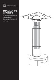
a fresh air supply set (accessory) is connected throughthe floor, mark where the hole should be.The insert expands when in use, and for thisreason the insert must NEVER rest on thesurround, but have a gap of about 3 mm. Theinsert must neither rest on the bench plate oragainst the sides. It is recommended to dry stackthe surround in order to adjust the insert prior toperforating the chimney for the flue connection.For the flue connection to the chimney, follow therecommendations from the chimney manufacturer.Operating controlFIG 9A/9B: The door is opened and closed by gentlypushing in the handle (about 10 mm) and then let it outagain.FIG 10: The air vent control is adjusted by moving thelever to the left.FIG 11A: Remove ashes by shaking the ash grate withthe cold-handle, or alternatively with a spade.FIG 11B: The ashtray is pulled out in front with the coldhandle.When the insert is in an upright position, and prior tomounting the surround, check that all functions areeasy to manoeuvre and appear satisfactory.Air vent control (FIG 10)LeftRightOpenClosedRemoving the self-closing mechanism FIG 12b1. Open the door.2. Use a pair of pliers and grab the long piece on thespring. Gently pull the spring down and off.Assembly instructions for the surround(FIG 13 - FIG 25)Acrylic glue is used for gluing the elements towardswall, gluing the elements together and for filling joints.When assembling, ensure that the vertical joints areabsolutely vertical(FIG 17).FIG 14: Place the bottom element and ensure that it islevelled. Adjust with wedges or powder glue if needed.FIG 19: Carefully tilt the insert backwards in order toplace the lockring.the glue is dry.Read the text on Adjustment for more information.FIG 25: Once the fireplace is assembled, fill the jointswith acrylic and even them out with a sponge orfinger and some soapy water, in order to have a clearindentation between the elements (FIG Z).6. Lighting the Fire for the First TimeWhen the insert is assembled and all instructions havebeen observed, a fire can be lit.Take care when inserting logs into the burn chamber,in order not to damage the Thermotte plates. Pleasenote that there might be some humidity in the insulationplates which can result in a slower burn rate the first fewtimes the insert is used. These will be resolved oncethe humidity has evaporated. Possibly leave the doorslightly open the first 2-3 times that the insert is used. Itis advisable to ventilate the room well when firingfor the first time as the varnish on the product mayrelease some smoke or smell. Both the smoke andsmell will disappear and are not hazardous.Lighting a fireInsert small dry pieces of kindling wood, ignite andensure that the flames have established on the woodbefore closing the door. Open the air vent control (FIG10) before the door is closed. Additional ignition airis obtained by keeping the door slightly ajar. The airsupply is regulated with the air vent control once theflames are stable and the chimney is warm.When there is a glowing layer of ash, new wood logscan be inserted. Pull the hot ember to the front of thecombustion chamber when inserting new logs so thatthe wood is ignited from the front. Keep the door slightlyopen each time new logs are inserted so that the flamesget established. The fire should burn with bright andlively flames.Using the insert with low combustion effect and firingaround the clock increase pollution as well as the riskfor a fire in the chimney. Never allow the insert or flueto become glowing red. Turn off the air vent controlshould this happen. Regulation of the air vent controltakes some experience, but after a little while a naturalrhythm for the fire will be found.FIG 20 / FIG 21 / FIG 23: Ensure that there is a gapbetween the insert and the surround as the insertexpand with heat.FIG 23: Place two wedges on top of the insert beforeassembling the top elements in order to avoid that theelement rests on the insert. Remove the wedges onceGB13