ARS-5 12-Volt Regulator - Balmar
ARS-5 12-Volt Regulator - Balmar
ARS-5 12-Volt Regulator - Balmar

Create successful ePaper yourself
Turn your PDF publications into a flip-book with our unique Google optimized e-Paper software.
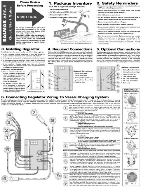
7. Basic <strong>Regulator</strong> DisplayOnce the basic installation (as described on the reverse page) iscompleted, the regulator should be activated when the ignition isturned on and/or when the engineis running. When activated, theregulator will scroll throughoperational data on its alphanumericLED display.Indicates <strong>Balmar</strong>.Indicates <strong>ARS</strong>-5 voltageregulator.Battery program setting. Defaultsetting shown. See Section 8 foradditional info.Belt Load Management setting.Values are b-0 to b-7. SeeSection 9 for additional info.Charging Stage. “-r-” is ramp,“-b-” is bulk, “-A-” is absorption,“-F-” indicates float stage.Battery voltage. Following value(in tenths) matches voltage atbattery being charged.Calculated volts. Indicates targetvoltage for each stage of charge.Based on program selected.Battery temperature. Followedby actual temp in celsius, orcode “nc” if not connected.Alternator temp. Followed byactual temp in celsius, or code“nc” if not connected.8. <strong>Regulator</strong> ProgrammingThree simple programming choices are all the <strong>ARS</strong>-5 requires to maximizecharging efficiency; select your battery type, set the Belt LoadManagement value, and select either the short display or the long display.In order to make programming as easy as possible, we stronglyrecommend that you read the instructions before attempting toprogram the regulator. Each segment has a space to write downyour desired setting prior to programming, so the information willbe close at hand when you enter the regulator’s programming mode.To enter the regulator’s programming mode:1. Make sure that the regulator is turned on and voltage is greater than<strong>12</strong> volts. If the display is scrolling, you’re ready to go.2. Hold the magnetic tip of the <strong>Balmar</strong> programming screwdriver to theRED DOT located in the upper left corner of the voltage regulator(just to the left of the LED display, if the readout is right side up).3. When the code “Pro” is indicated on the LED display, release themagnet from the RED DOT by pulling the screwdriver away from thesurface of the epoxy potting.4. The <strong>ARS</strong>-5 will begin to scroll through the programming selections,beginning with Battery Program Type (see Section 9).NOTE: Any of the programming modes can be changed at any time.Simply follow the instructions in Sections 9 to 11 to make changes.9. Set Program For BatteryOnce you have entered into the programming mode as described inSection 8, the LED display will indicate “bA” indicating the batteryprogram mode. When the display indicates “bA”:1. Hold the magnetic tip of the <strong>Balmar</strong> programming screwdriver tothe RED DOT. When the magnet is activated, the LED will begin toscroll through the battery program selections.2. When the code for the battery program you desire is indicated inthe LED display, release the magnet from the RED DOT. The displaywill return to the “bA” code, atwhich time, you can re-applythe magnet to change yourselection.4. If you are satisfied with yourselection, keep the magnetaway from the RED DOT. Aftera couple of seconds, the LEDwill indicate “bEL”, indicatingentry into the Belt LoadManagement mode. (SeeSection 10.)Enter your preferred setting hereUFP - Universal FactoryProgram. Default programis safe for all battery types.FDC - Flooded Deep Cycle.For thick plate flooded leadacid batteries.GEL - For silica gel filledbattery technology.AGL - Absorbed Glass Matbattery technology.OPS - Spiral Wound AGM(Optima-type) batterytechnology.10. Belt Load ManagementYour alternator’s drive belt limits the size of Enter your preferred setting herethe alternator amperage output. Typically, ahigh-output alternator will apply up to onehorsepower of load to the drive belt for each25 amps it creates, so a 100-amp alternatorcould place a 4 h.p. load on your belt.The <strong>ARS</strong>-5 controls the load placed on the drive belt by limiting the regulator’smaximum field potential. The chart at right provides a guideline for determiningthe appropriate Belt Load Management setting based alternator output and thewidth of the drive belt.While the values shown in the chart are a fine starting place, it may benecessary to make further adjustments should you find that you areexperiencing belt dusting or premature belt failure. The greater the Belt LoadManagement value, the lower the demand placed on the drive belt.To adjust the Belt Model Management setting:1. During programming, the Belt Load Management mode is indicated by thecode “bEL” on the LED display. When “bEL” is is shown, hold the magnetto the RED DOT on the regulator’s epoxy potting.2. The display will indicate a series of values ranging from “b-0” to “b-7.When the value that matches your belt width and alternator output isreached (see the chart above) release the switch. Boxes marked with “NR” indicate that the alternator output tobelt width are not recommended.3. The Belt Load Management setting can be accessed and re-adjusted at any time that the regulator is active. If youfind that the alternator load is causing black belt dust, access the Belt Load Management program by applying andholding the magnet to the RED DOT until “PRO” is indicated. Release the magnet until the “bEL” code is indicated.Re-activate and hold the switch until the desired value is indicated and release.11. Long <strong>Regulator</strong> DisplayAt the time that you program theregulator for battery type and belt loadcontrol, you have the option to selectthe amount of information theregulator displays during normaloperation.For most applications, the regulator’sshort display (see Section 7 above fordetails) will provide all of theinformation required to monitornormal operations. Should you preferto see the longer, more detaileddisplay, select the regulator’s longdisplay mode.Following the Belt Load Management mode, the regulator will indicate“dSP” to note entry into the short-long display adjustment mode. Tochange from short to long display mode:1. Hold the magnetic tip of the screwdriver to the RED DOT when the“dSP” mode is indicated. The regulator display will scroll between“Sd” and Ld”. Release the switch when the desired mode isindicated.2. The regulator will scroll through the programming mode threetimes before saving programming changes. You can make changesto any of your desired settings during those three opportunities.The regulator will indicate “SAV” when programming is complete.Indicates <strong>Balmar</strong>.Indicates <strong>ARS</strong>-5 voltageregulator.Battery program setting. Defaultsetting shown. See Section 9 foradditional info.Belt Load Management settingmodifies field current level. SeeSection 10 for additional info.Charging Stage. “-r-” is ramp, “-b-” is bulk, “-A-” is absorption,“-F-” indicates float stage.Battery voltage. Following value(in tenths) must match voltage atbattery being charged.Calculated volts. Indicates targetvoltage for each stage of charge.Based on program selected.Battery temperature. Followedby actual temp in celsius, orcode “nc” if not connected.Alternator temp. Followed byactual temp in celsius, or code“nc” if not connected.Enter your preferred setting here“dSP” Indicates entryinto Short/Longdisplay mode.Short DisplayLong DisplayField Output - Percentage ofregulator field output. Followedby zero to 100% value.Software revision level.<strong>Regulator</strong> circuit board temp.Followed by actual circuit boardtemperature in degrees celsius.Factory use only.Indicates total regulator runtime. Followed by time in twodisplays: tenths / hundredsFactory use only.Factory use only.Event Codes: Indicates eventsand advisories. Individual codesare shown in chart at right.“bEL” Indicates entryinto Belt LoadManagement mode.“b-0” Indicates 100%(un-governed) fieldoutput. Full power.“b-7” Indicatesmaximum Belt LoadManagement (50%±).<strong>12</strong>. Alternator Temperature Sensor (MC-TS-A)When the Alternator Temperature Sensor is installed, the <strong>ARS</strong>-5 monitorsthe alternator for safe temperatures and responds by reducing field output ifthe alternator exceeds safe working temperature. In addition, the regulatorwill activate the DASH LAMP circuit to indicate that a condition has occurred.To install the Alternator Temperature Sensor:1. Connect the lug end of the temperature sensor to the case mount boltof the alternator, or alternate location indicated in your alternatorinstallation instructions.2. Plug the positive and negative female spade terminals at the other endof the sensor cable into the AlternatorTemperature Sensor terminals as indicated onthe side of the regulator. Ensure that thepositive (red) and negative (black) wires areconnected to the correct terminal. Observepolarity.13. Battery Temp. Sensor (MC-TS-B)The Battery Temperature Sensor (MC-TS-B) enablesthe <strong>ARS</strong>-5 to automatically respond to increases anddecreases in ambient battery temperature byincreasing or decreasing charging voltage specific toeach battery type. In the event of a thermal runawayevent at the battery, the regulator will discontinuecharging completely and activate the DASH LAMPcircuit. To install the Battery Temp Sense cable:1. Connect the lug end of the temperature sensorto the negative post of the battery BEINGCHARGED. If there are more than one battery inthe bank, connect to the negative post closestto the center of the battery bank.2. Plug the positive and negative female spadeterminals at the other end of the sensor cableinto the Battery Temperature Sensor terminalsas indicated on the side of the regulator. Ensurethat the positive (red) and negative (black)wires are connected to the correct terminal.Observe polarity.14. Dash Lamp TerminalThe Dash Lamp terminal provides a .5A negativeoutput when one of the following events occurs: lowbattery voltage, high battery voltage, high batterytemperature or high alternator temperature.The Dash Lamp terminal can be used in conjunctionwith your choice of an indicator lamp or audibledevice requiring up to .5A to operate. <strong>Balmar</strong>’sModel AAK (Audible Alert Kit) can be used inconjunction with the <strong>ARS</strong>-5 regulator.Factory use only.Factory use only.Factory use only.Factory use only.Small Engine Mode.Factory use only.Factory use only.15. TroubleshootingThe <strong>ARS</strong>-5 voltage regulator is designed to provide safe, dependable service. Shouldyou find that the <strong>ARS</strong>-5 is not working properly, follow these instructions to identifypotential sources of difficulties.Most regulator failures can be traced to wiring issues. Please identify the symptomthat best describes the problem your system is experiencing, and follow theinstructions for troubleshooting:System does not charge. No display on regulator.1. Check voltage on RED (power) wire in wiring harness. <strong>Volt</strong>age should matchvoltage at battery being charged, and must be above <strong>12</strong> volts DC.a. If voltage at the RED wire is zero, inspect the wire at its source toensure that it is properly connected. Measure voltage at the other end ofthe RED wire (source). <strong>Volt</strong>age should match the voltage at the batterybeing charged.b. If the voltage at the source matches the voltage at the battery beingcharged, but the voltage at the regulator side of the RED wire is zero,check and/or replace the 10A ATC-type fuse found in line near the source.Re-measure voltage. If zero, inspect the length of the RED wire andconnectors for damage.2. Check voltage on BROWN (ignition) wire in wiring harness. <strong>Volt</strong>age mustmeasure greater than 11 volts.a. If voltage at the BROWN wire is zero, inspect the wire at its source todetermine if 11+ volts is present. If voltage is below battery voltage, tracethe ignition circuit to its source and correct voltage loss.3. Check continuity between the regulator’s BLACK (ground) wires and systemground. Most handheld multimeters feature an audible continuity circuit or ohmmeter. If the BLACK ground wires indicate poor or no continuity, inspect andcorrect ground connections between the regulator and the alternator, as well asthe connections between the alternator ground terminal and system ground.4. If all of the wiring connections at the regulator meet the expected values, but the<strong>ARS</strong>-5 display does not illuminate and the system does not charge, contact<strong>Balmar</strong> Customer Service at 360-435-6100 for technical assistance.System does not charge. Display is illuminated.(Note: When checking system, wait for start delay period to complete beforechecking regulator voltages. Stage code -b- should be indicated in the short display.Be sure that shore power charging IS NOT connected while testing.)1. Check voltages on RED and BROWN wires as described above.2. Check continuity on the BLACK wires as described above.3. Check voltage on BLUE (field) wire in wiring harness. <strong>Volt</strong>age should measureapproximately three to eleven volts, depending on the charge level of thebatteries. Field voltage increases as batteries are more deeply discharged.a. If voltage on the BLUE wire measures less than one volt at theregulator plug, unplug and re-plug the black four-wire plug into theregulator. Re-check voltage.4. If voltage on the BLUE wire is still less than one volt, disconnect the BatteryTemperature Sensor wire at the regulator. If the BLUE wire voltage increases tonormal levels, shut the system down immediately and inspect the batteries forabnormal temperature levels (Battery temperature can also be determined bymonitoring the B1 reading on the regulator display). If the temperature of all thebatteries is normal, replace the Battery Temperature Sensor.5. If the voltage on the BLUE wire stays below one volt after all of the preceedingsteps, contact <strong>Balmar</strong> Customer Service at 360-435-6100 for assistance.System voltage exceeds program target voltage levels(Note: When checking system, wait for start delay period to complete beforechecking regulator voltages. Be sure that shore power charging IS NOT connectedwhile testing the alternator and regulator.)1. Compare voltage on the regulator’s RED wire with the voltage at the batterybank being charged. If voltage at the regulator end of the RED wire is lower thanthe voltage at the battery, trace the length of the RED wire to it’s source andcorrect any connections or wire damage which could be causing voltage drop.If the RED wire is connected to the alternator or the common side of a batteryswitch, trace positive cabling to the battery and correct faults causing voltagedrop.2. If an isolator is being used to control charge flow, ensure that the RED wire fromthe regulator is connected to the battery side of the isolator at the terminalconnected to the main (house) battery bank. If charging voltage at the batterybanks being charged differs, a replacement isolator or an alternative chargecontrol device may be required to remedy the problem. If the regulator is usedwith a 6-Series alternator, see www.balmar.net for details on required diodes.3. If the voltage is 14.8 volts or less, disconnect the Battery Temperature Sensor,if installed. If the voltage returns to normal levels, the change in voltage is dueto temperature compensation based on ambient battery temperature.4. If high voltage at the battery is equal to the high voltage recorded at theregulator, and voltage exceeds 15+ volts, and no other charge sources are inuse (solar, wind, etc.), shut down the system and contact our Customer Servicedepartment at 360-435-6100.If you do contact <strong>Balmar</strong> Customer Service:Have the following information available:1. <strong>Regulator</strong> Model and date of manufacture (stamped on side of regulator).2. Record of voltage measurements taken.3. Full list of Event Codes shown in the regulator’s Long Display (if accessible).4. Purchase location and date of purchase.1. Manufacturer and model of alternator being used.