
Create successful ePaper yourself
Turn your PDF publications into a flip-book with our unique Google optimized e-Paper software.
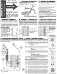
Seawater and Freshwater SupplyINSTALLATION PROCEDURESSeawater supply hose must be a minimum of 5 /8" ID and must not be obstructed byundersized sea water strainers, fittings, or sea cock valves. We recommend seawater hoseand fittings be a minimum of 3 /4". The larger the sea strainer, the better. Do not share theseawater inlet with the main engine through-hull unless a sea chest is available.If your system is fitted with a watermaker, ensure that the seawater intake is locatedforward of the head discharge or any other discharge that could foul your watermaker’ssupply source.If the unit is installed below the waterline, a vented loop is required. The seawater supplyline feeding raw cooling water into the system must be routed to prevent siphoning of rawwater through this line into the exhaust system, filling the muffler and engine cylinders.This line should be routed at least 12 inches above the waterline and an anti-siphon breakinstalled the top of its loop. This loop should be high enough above the waterline to ensurethat it remains dry even while heeling.A small freshwater supply tank (expansion tank), bracket, and 10' of 3 /8" clear hose aresupplied with the unit and should be mounted level with the genset’s heat exchanger.Exhaust SystemEngine exhaust elbow is 1 3 /4”. Exhaust line installations will vary considerably and eachmust be designed for the particular installation. The prime requirement is to provide anoutlet line with a minimum of restrictions, situated in a manner that ensures seawater,rainwater and condensation cannot get back into the cylinders of the engine. Most exhaustsystems today use a water lift muffler such as the Vernay or Vetus type.- 3 -
5. Once aligned, insert the 30mm Capscrews into the three radial cavities in theLovejoy. Tighten each capscrew just far enough to ensure proper threading untilall screws are properly aligned and threads are started.6. When all three capscrews are in place, Tighten to 20 ft.lb. It may be necessary,once all capscrews are in place, to turn the crank pulley on the engine to accessall of the capscrews for torqueing.7. Inspect the Lovejoy forproper alignment asillustrated at right.Loosen capscrews andre-tighten, if necessary,to ensure that theLovejoy is free fromdistortion.8. Re-check torque.Shows correct and incorrect radial coupling alignment.9. Replace Cat Pump platform.10. Re-connect wiring connections at alternator as described in the alternator manualincluded in the genset instructions.Notes:- 6 -
Key PanelElectrical Connections for 12V<strong>DC</strong> motor functions are made at the molded plugs at theengine. One 20' extension cable is supplied with each system. There is a 25-amp fuse atthe engine for panel and wire protection. The engine is supplied with oil pressure andtemperature switces, and will shut down the engine in the advent of a malfunction. A redLED on key panel would indicate this.Key Panel includes:1. Key Switch2. Hour Meter3. Toggle-Adjustable Speed Control for manual control of engine throttle4. Toggle switch to turn ON-OFF system alternator5. Digital voltage meter indicating system voltage - gray wire at ESC box should beconnected directly to positive post at battery bank Wire should be fused near batteryat three (3) amps..6. Mini toggle switch for ON-OFF system voltage meter7. Pre-Heat, Run, and Alarm LEDs.PARTS REQUIRED FOR INSTALLATIONFollowing is a general list of parts needed for installation. This is just a general list, as allboats are different and installation is unique to each one.Mounting <strong>Genset</strong>1. (8) 5 \16 Hex Bolts or Lag Bolts, w/nuts and washers as needed. Primary Fuel Filterand Water Separator w/ fittings2. 1/4" Fuel Hose w/clamps (fuel supply)3. 1/4" Fuel Hose w/clamps (fuel return)Fittings as needed to install hoses to boats fuel systemSeawater Supply1. Seawater Through-Hull fitting ( 3 /4" or larger)2. Seawater Intake Valve (ABYC approved)3. Sea Strainer (minimum ¾")4. Vented Loop fitting, optional (not necessary if mounting above water line).5. Fittings as needed to make up intake valve, sea strainer and through-hull6. 5\8" or 3 \4" Intake Hose w/clampsExhaust System1. Exhaust Through-Hull fitting (1¾")2. Water Lift Muffler (1¾")3. 1 3 \4" Marine Exhaust Hose w/clampsStarting System1. Start Battery w/lugs2. Start Battery Cables (minimum #6 AWG) w/terminals- 7 -
PARTS REQUIRED FOR INSTALLATION (Continued)Battery BoxAlternator SystemSystem Battery Cables (minimum #1\0 AWG - determined by length of run & percentageof line loss).TROUBLESHOOTING<strong>Balmar</strong> equipment manuals contain a user friendly troubleshooting section. This information is alsoavailable at our web site: www.balmar.net. Personal assistance in troubleshooting equipment isavailable through our Technical Support Department via E-mail (balmar@balmar.net) or phone (360-435-6100, ext. 3). Our hours of operation are Monday - Thursday, 7:30 am - 5:30 pm PST. We areclosed Friday - Sunday. There are endless possibilities that can cause a system to not operateproperly, other than equipment defect. It is the responsibility of the owner to either troubleshoot thesystem or hire a qualified professional to do so.Non-Warranty Repair: If failure is found to not be covered under the terms of this warranty, customerwill be presented with price to repair / replace. If repair / replacement is declined, equipment will bereturned to customer as stated under #4, Return to Customer, or will be disposed of upon request.Loaner Equipment: <strong>Balmar</strong> does not provide equipment for loan to be used while failed equipmentis undergoing analysis. If replacement equipment is required prior to warranty analysis, newequipment can be purchased. Used equipment may be offered for sale, subject to availability.LIMITED PRODUCT WARRANTYBALMAR warrants to the original consumer/purchaser the product is free from any defects in material or workmanship for a period ofone year from the date of purchase. This warranty DOES NOT apply to defects or physical damage resulting from abuse, neglect,accident, improper installation, wiring, or repair, alteration, modification, or unreasonable use of the products resulting in breakdown,cracked or broken cases, parts damaged by fire, water, freezing, collision, theft, explosion, rust, corrosion, overheating or itemsdamaged in shipment in route for repair. BALMAR assumes no responsibility for consequential damage or loss or expense arising fromthese products or any labor required for service or repair. Alternators are not covered when used with manual regulation devices.Following are requirements for determining warranty coverage:1. Proof of Purchase: All <strong>Balmar</strong> equipment is production dated. This date is not adequate for warranty consideration, as newproduct can age significantly prior to end user purchase, installation, and placement in service. Proof of purchase isrequired for accurate calendar consideration.2. Analysis of Failure: All equipment will be factory analyzed to determine warranty status prior to replacement or repair.Contact <strong>Balmar</strong> for return authorization (RA) number. <strong>Balmar</strong> can not be held responsible for any product sent withoutproper identification, return address, and RA number clearly marked on the package. Ship equipment prepaid to thelocation specified by <strong>Balmar</strong>. This warranty is not extended to costs of troubleshooting, including time, labor, orcommunication costs incurred either with <strong>Balmar</strong> or other marine specialists.3. Determination of Warranty: If the equipment is found, upon analysis, to have failed under the terms of this warranty, it willbe repaired or replaced. <strong>Balmar</strong> reserves the right to determine whether to repair or replace components. Allow 30 daysA.R.E. (after receipt of equipment - expedited service is available upon request whenever possible). This warranty is in lieuof all implied or verbal warranties as to the merchant ability or fitness for a particular application. No person is authorizedto repair, modify or assume additional obligations for warranty without the written authorization of a <strong>Balmar</strong> corporateofficer.4. Return to Customer: Once analyzed, equipment will be returned by surface freight to continental US destinations.International and offshore 'ship to' addresses, as well as 'rush' and expedited shipment requests, will require credit card forpayment of freight charges.THE ABOVE LIMITATIONS MAY NOT APPLY TO YOU. SOME STATES DO NOT ALLOW LIMITATIONS ON HOW LONG AN IMPLIED WARRANTYLASTS. NO PERSON, AGENT, DEALER IS AUTHORIZED TO GIVE ANY WARRANTY OR REPRESENTATION ON BEHALF OF BALMAR UNLESSMADE IN WRITING BY AN OFFICER OF BALMAR.- 8 -
Aqua Pac VoyagerOperations <strong>Manual</strong>Control Panel & CPMPre-Filtration ModuleFeedwater PumpRO MembranesIntroductionThe Aqua Pac Voyager is a revolutionary concept in providing fresh water from seawater forpleasure boats and for remote residences and encampments. The integrated desalinatoris nominally rated at either 20 or 40 gallons per hour. The APV system is modular in design,combining required components, whether installed on a <strong>Balmar</strong> PC-750 or PC-850 <strong>DC</strong><strong>Genset</strong> or used on its own.Aqua-Pac desalinator operates on the principle of reverse osmosis. The ions (salt) inseawater tend to form into clusters, which are many times larger than the individual purewater molecules. Under pressure, the pure water molecules are forced through a semipermeablemembrane leaving the ion clusters behind. Although a simplification, this isbasically how reverse osmosis works.In actual practice, the feed-water is drawn from the source through a coarse strainer,through three stages of filtration, and delivered to the inlet of a three cylinder reciprocatingpump which is belt or direct-driven by the engine. This "high-pressure pump" forces thefeed-water through the membrane, through a variable restrictor or "RO Pressure Regulator",and out to discharge. The RO pressure regulator creates the back pressure applied to thefeed-water in the high-pressure vessel.While ionized feed-water, under pressure, is being forced over the membrane, pure wateris permeated out of the membrane and is called "product water". The product water passesthrough a flow meter, which indicates the amount being produced, in gallons per hour.- 9 -
From the flow meter, the product water enters a chamber called the "salinity cell" wheretwo probes measure the electrical resistance of the product water. The residual ion contentof the product water is inversely proportional to its electrical resistance, totally de-ionizedhaving infinite resistance. Typical resistance of the product water will be in theneighborhood of 1500 ohms. The purity of the product water may also be expressed inmhos where the value would be the reciprocal of that in ohms. Additionally, the purity maybe expressed as parts per million of total dissolved solids. The PPM value (at levels foundin product water) is roughly half of the value in micro-mhos.If the salinity cell and associated circuitry determines that the product water is ofacceptable quality, an electric "diversion" valve is opened and the product water is allowedto flow into whatever storage facilities are provided. Should the vacuum at the inlet of thehigh pressure pump become abnormally great due to clogged pre-filters or some othercause, an automatic circuit will stop the system and activate a "HIGH INLET VACUUM" light.RO pressure is indicated on the RO pressure gauge. Pressure in excess of 1000 PSI willtrigger the pressure relief valve.Central Processing Module (CPM)The Central Processing Module is equipped with the system control switch, start buttonand all annunciator lamps. As will as the product water flow meter, salinity probe (MPU) inwhich water quality is measured, and the electric diversion valve (Burkheart valve) whichdirects potable product water into the storage tanks. The front of the CPM forms thesystem's main control panel.Pre-Filtration ModuleThe Pre-Filtration Module is a three-stage filter system that removes suspended particulatematter from the incoming feed-water. Efficient pre-filtration contributes greatly toprolonging RO membrane life. The first stage consists SS strainer screen (Plankton filter)housed in a clear plastic bowl. The second stage is a 577 square inch, pleated-paper 50-micron filter. The third stage is a 5-micron filtration cartridge.The SS strainer screen (Stage 1) can be cleaned and reused over again. The 50 and 5-micron cartridges should be replaced as needed. You may want to save the best of theused, 5-micron filters for the cleaning process. A relay module mounted on the pre-filterassembly operates the electric clutch at the feedwater (Cat) pump and the pre feed pump(water puppy). The primary system fuse and over-ride switch used when performing thecleaning and preserving tasks, as well as terminal strips for convenient wiring are alsomounted on this relay module.Reverse Osmosis Module (ROM)The Reverse Osmosis Module is where de-ionization takes place. Feed-water (seawater)under pressure flows out the high-pressure pump module and through the ROM highpressurevessel past the reverse osmosis membrane inside the pressure vessel. Purewater molecules permeate through the membrane fabric where they are collected andmanifold to a tube in the center of the membrane.This "product water" then flows back into the Central Processing Module for furtherprocessing. Meanwhile, the feed-water that did not permeate through the membrane flowsto the Pressure Regulator Module and is subsequently discharged as waste overboard.- 10 -
Pressure RegulatorThe Pressure Regulator consists of a manual pressure regulator and a pressure gaugemounted on the control panel. The regulator maintains the proper back pressure on themembrane.Control PanelThe Control Panel permits operation and monitoring of the system from a convenientlocation such as in the living quarter of a boat.Feedwater PumpThe Pre-feed pump consists of a separate relay controlled pump that forces feed-waterthrough the pre-filters. Installation of a feed-water pump will decrease pre-filtermaintenance, system noise and vibration and RO pressure pump wear. If either the engineor the Pre-Filtration Module must be mounted more than two feet above the feed-watersource level, a Feed-water Pump Module will be required as well as a check valve. A FeedwaterPump Module is recommended for all installations.Emulsion Removal Module (ERM) OptionalThis unit removes oil or silt from the feed-water, to further protect the RO membrane. Thiselement should be replaced as soon as oil is detected or every year during normalservicing.Plankton Filter Assembly OptionalThis is a 50-micron SS element that works more efficiently than the sea strainer and neverneeds to be replaced -- just cleaned on a normal basis. This will not replace a sea strainer.Ultraviolet/Charcoal Sterilizer OptionalAlthough the RO process is very effective at removing bacteria and other pathogens fromthe feed water, a UV/Charcoal Sterilizer can be added that will function as a second line ofdefense against any micro-organisms that may have penetrated the RO membrane. The UVSterilizer is recommended anytime the desalinator is going to be used in brackish orsewage contaminated waters. The charcoal element removes foul odors and tastes in theproduct water. The charcoal filter is rated at .5 micron and should be replaced every year.It is a special style charcoal filter, call <strong>Balmar</strong> for replacement. The UV bulb should bereplaced every 2000 hrs. or every two years. After recommended replacement time, thespectrum of the light will shift and cause insufficient radiation of the bacteria and viruses.Supplemental FiltersA 5 micron filter is standard with the Aqua-Pac. 5 and10 micron filters are available in thestandard size. Larger surface area filters are also available in various micron sizes. Mediafilters are available for land based or commercial applications.Freshwater Flush Assembly OptionalThis is a charcoal filter and three-way valve assembly designed to be installed onto thefresh water system for flushing the salt water out of the desalinator. Not intended for longshut down periods. Up to one month before re-flushing is required.- 11 -
<strong>Watermaker</strong> SpecificationsFeed-water pH Range: 3-11Feed-water Temperature Range: 40° to 100°F (4.4°C to 37.8°C)Membrane Salt Rejection: 98.6 % or greaterMaximum Operating Pressure: 800 PSICpm Switched Accessory Terminal Output: 6 Amps @ 12 V<strong>DC</strong>High Pressure Pump Crankcase Lubricant: <strong>Balmar</strong> P/N 334-010High Pressure Pump Crankcase Capacity: 12 oz*All performance specifications are with feed-water salinity of 35,000 PPM, feed-water pH of 8, feed-watertemperature of 77°F (25°C), and operating pressure of 800 PSI. Product water output will decrease with lower feedwatertemperatures. Rated output at a given temperature is +/- 15%.Replacement PartsGenuine <strong>Balmar</strong> replacement parts as well as modules and accessories are available fromauthorized <strong>Balmar</strong> dealers. As a convenience to <strong>Balmar</strong> product users, replacement partsare also available directly from <strong>Balmar</strong> Products.WARNING: Use of other than genuine <strong>Balmar</strong> replacement parts may impair theperformance and/or inherent safety of the system and may also void the warranty.Replacement parts obtained from dealers are not necessarily genuine.Desalinator OperationInitial <strong>Watermaker</strong> StartupNOTE: If there is a chance that the ROM will be subjected to freezing temperatures duringthe lay-up, remove the high pressure vessel, seal the vessel ports with the caps suppliedin the Cleaning/Biocide Kit, and place the vessel in a storage location whose temperaturewill be maintained between 50°F (10°C) and 75 °F (24°C). A food grade preservative isavailable from <strong>Balmar</strong>, should removal be difficult. This acts as an appropriate anti freeze.But it is not rated below 20 F.CAUTION: Allowing the membrane to freeze will cause permanent damage.The following procedure should be used for new installations and for returning systemsto service after a prolonged shutdown.1. De-energize the Desalinator circuit breaker. Ensure that there are no explosivevapors present in any of the compartments where components of the Desalinatorare located. (This step is primarily for installation in hazardous locations such asoffshore oil platforms and gasoline powered boats.)2. Ensure that the high-pressure pump crankcase is filled to the red dot on the oillevel indicator.3. Set the Product Water Control valve to normal.4. Open all feed-water inlets.- 12 -
5. Start the engine.6. Set the Master System switch to "manual" at the control panel.7. Turn the RO pressure valve all the way counter-clockwise, to ensuring that nomembrane preservatives enter the product water storage tank.8. Press and release the desalinator start switch.9. Check the entire system for leaks. If any are found, stop the system and correctas necessary.10. If the system should stop automatically, refer to “Troubleshooting Section” forpossible causes.11. After the system has run for 2 hours, slowly turn the RO pressure valve clockwiseuntil the RO pressure gauge registers 800 PSI or rated flow of the membrane (i.e.20 G.P.H.) whichever occurs first.12. Check for leaks.13. Wait for the product water flow meter to stabilize. Adjust the RO pressure valve sothat the flow meter indicates approximately the proper product water flow for thegiven feed-water temperature. (Refer to Section 1.4)14. Again, check the entire system for leaks.Routine Start-UpThe following procedure should be used if the desalinator has been operated within theprevious 14-day period. For newly installed systems or systems that have been laid up formore than 2 weeks, refer to "INITIAL START-UP PROCEDURE". (In general, systems shouldbe operated at least once every 14 days, as some of the system components deteriorateover long periods of idleness. This is especially true of the RO membrane, although theprolonged shut down procedure will help retard the deterioration.)WARNING: This desalinator during the course of normal operation generates electricalarcing that could ignite explosive vapors. Do not attempt to operate the system if anyexplosive vapors are present.1. Ensure that there are no explosive vapors present in any of the compartmentswhere components of the desalinator are located. (This step is primarily forinstallations in hazardous locations, such as offshore oil platforms and gasolinepowered boats.)- 13 -
2. Ensure that all feed-water valves are open.3. Start the engine. Allow a few minutes to warm up.4. Activate the desalinator start switch.5. Verify that the "CLUTCH ENGAGED" light is on.Periodically, verify that the product water flow--meter indicates approximately the properproduct water flow for the given feed-water temperature. (Refer to Section 1.4) (This shouldbe done immediately whenever it is suspected that the feed-water salinity has changed -such as when cruising from a river to open ocean.) Do not exceed the rated production ofthe membrane. Adjust the RO pressure regulator to correct.WARNING: Ingestion of oil and some chemicals are harmful to the RO membranes. Do notoperate the system using feed-water sources containing these substances.Routine <strong>Watermaker</strong> ShutdownIf it is certain that the system will be operated within the subsequent 14-day period, switchoff system switch to shut the system down.Prolonged <strong>Watermaker</strong> ShutdownIf the system is to be left idle for more than 30 days, the RO membrane must be injectedwith a biocide solution to prevent the growth of microorganisms in the membrane. If theunit will not be used for 14-30 days a fresh water flush may be used to remove theorganisms.CAUTION: Microorganism growth in the RO membrane will degrade membraneperformance.In order to inject the RO membrane with biocide, it can be removed and taken to anauthorized desalinator repair facility or a Cleaning/Biocide Kit may be used. Refer to thekit instructions for the proper procedures. Flush kit assemblies are available at BALMAR.Temperature Effect on System PerformanceFeed-water temperature has a significant effect on the productivity of reverse osmosisdesalinator. In order to obtain round GPD numbers, the performance of the systems isspecified operating with 77°F (32°C) feed-water. As can be seen from the graph on thefollowing page, product-water output increases as feed-water temperature increases anddecreases as feed-water temperature decreases.As the feed-water temperature increases the membrane's salt rejection decreases slightly.This means that the product water will have slightly higher residual salt content. Thischaracteristic is most noticeable at feed-water temperatures in excess of 90°F (32°C).Freshwater Output CorrectionRO desalinator performance varies greatly with feed-water temperature. To compute theexpected output, multiply the correction factor by the nominal rating.- 14 -
Feedwater Temperature Correction Factor40°F (4.44 °C) .37350°F (10°C) .53560°F (15.6°C) .69570°F (21.2°C) .89577°F (25°C) 1.0080°F (26.7°C) 1.0890°F (32.2°C) 1.27100°F (37.8°C) 1.47Properties of Reverse Osmosis WaterThe purpose of a reverse osmosis desalination system is to remove a large percentage ofthe dissolved minerals (salt) in sea or brackish water. Systems operating withinspecification typically will remove at least 98% of the "salt" in seawater, generating productwater with mineral content of less than 750 parts per million.The reverse osmosis process used in the Aqua-Pac can be highly effective at removingbacteria and other pathogens from the feed-water. The degree of effectiveness dependsupon such factors as the age and condition of the semi-permeable membrane and on theconcentrations and types of pathogens contained in the feed-water.The product water from an RO desalination system is typically fed to storage tanks ofunknown sterility where it may sit, stagnant, for weeks at a time before being used.Compounding the problem, storage tanks are sometimes filled by sources other than theRO system.If the water in the storage tanks is to be used for human consumption, <strong>Balmar</strong>recommends that steps be taken to ensure that the water does not contain unsafe levelsof pathogens.One method is to chlorinate the water in the storage tanks. Chlorine tablets and chlorineinjection systems are available to treat drinking water. If the water is to be chlorinated,follow the manufacturer's directions precisely.Chlorinating unfortunately does not remove any objectionable tastes or odors that thewater may have absorbed in the storage tanks. The chlorine will actually add taste andodor to the water. Also, the chlorine may react unpredictably with any chemicals, whichmay have gotten into the tank.<strong>Balmar</strong> offers various post-filters and an ultra-violet sterilizer/ charcoal filter to treat thewater before it goes into the water tank and as it comes out of the water tank. Contact yourdealer for more information.<strong>Watermaker</strong> InstallationPay particular attention to how the exhaust system will be routed from the engine. Keep inmind that the exhaust tube will probably have to rise higher than the engine so that nowater can enter the engine from the outside.Central Processor Module MountingThe CPM (Control Panel) may be either surface mounted or through a cutout in a bulkhead.Locate a suitable mounting place for the CPM. In order to obtain accurate readings fromthe product flow meter, the CPM must be mounted vertically.- 15 -
Product Water Outlet ConnectionThe product water outlet on the CPM is a barbed fitting for connection to 3 /8" ID hose. Thefitting is attached to the diversion valve that is mounted on the back of the CPM. Theproduct water outlet hose will carry water to the storage tank. Use only food-grade hose(suitable for carrying fluids for human consumption and capable of withstanding workingpressures of 50 PSI). Suitable hose is available from your dealer (P/N 210-005).Route the hose to the water storage tank using the most direct path. Secure the hose soit will not be abraded or pinched. The storage tank must be vented to atmosphere and theproduct-water hose must feed into the top of the tank so that the product water can flowfreely into the tank with no restriction or back pressure. Excessive back pressure willreduce or stop the flow of product water from the CPM.If the top of the storage tank is more than 15 feet above the CPM, a pump will have to beused to help lift the product water. Contact a dealer or the factory for details. Use a 3 /8"hose barb fitting and suitable adapters, if necessary, to connect the product water hose tothe storage tank. These fittings are available from your dealer. Secure the hose to thebarbed fittings using suitable hose clamps.Waste Product Water Outlet ConnectionsOn the Control Panel is a barbed fitting for 3 /8" ID hose. A hose connected to this fittingwill carry rejected product water overboard. Install a suitable discharge fitting above thevessel's water line and connect the 3 /8" ID hose. Secure each hose end with hose clamps.It is very important that no valve be installed in either of these lines since any restrictioncould damage the RO membrane.Input 12V<strong>DC</strong> Power ConnectionA separate source of 12 V<strong>DC</strong> power is required for the Aqua-Pac integrated desalinator. Thepower should be a 12 V<strong>DC</strong>-20 amp circuit protected by a 20-amp circuit breaker. (Thiscircuit is usually connected to the boat's main <strong>DC</strong> electrical panel).This input power is connected to the "12 V<strong>DC</strong> IN" terminals on the Pre-Filter Relay Module.Use 12 AWG wire for runs of up to 25 feet. Runs of over 25 feet require 10-gauge wire.Protect the wire feed with a circuit breaker in the positive leg of the feed as close aspossible to the main power panel or bus. Be extremely careful to connect the positive leadto the "+" terminal and the negative lead to the "-" terminal. Label the circuit breaker"DESALINATOR" or "WATERMAKER".Connecting Electrical Control Cable Between CPM and Pre Filter PackA 25' length of 6-conductor cable is supplied for connection between the terminal strip onthe back of the CPM and the junction box on the side of the pre filter pack.<strong>Watermaker</strong> Pre-Filtration Module InstallationThe Pre-Filtration Module should be mounted slightly above the source level (waterline) onmarine installations since most of the components are made of plastic and failure of acomponent could result in flooding of the vessel.Select a mounting site that will support the weight of the PFM when filled with water, willallow easy access for maintenance, and that will have enough clearance below forremoving and reinstalling the filter bowl. If the top of the PFM has to be mounted more than3 feet above the source level, a feed-water pump will be required or the PFM filter element- 16 -
and high pressure pump seal life will be unacceptable. It should be noted that a Feed-waterPump Module will enhance the operation of any system, regardless of where the PFM ismounted in relation to the feed-water supply level and is supplied with this system.Water ConnectionsUse 3 /4" ID food-grade suction hose to connect the outlet of the Feedwater Pump Moduleto the inlet of the Pre-filtration Module (PFM) and the outlet of the PFM to the feed-waterinlet of the Pump/Clutch Assembly. Secure all connections with hose clamps, using twoclamps at each connection for additional safety.Avoid unnecessary bends or rises in the feed-water hose. Protect the hose and fittings frommechanical damage as a leak in the feed-water hose of a marine installation could causeflooding of the vessel. Follow good marine practice for all marine installations. Consult aqualified marine installer if in doubt.Remember that all fittings used must be made of non-ferrous materials such as PVC,brass, bronze, or 316 stainless steel. Rust from ferrous materials will permanently damagethe reverse osmosis membrane.Marine installations should have a 3 /4" or larger bronze through-hull fitting installedthrough the bottom of the vessel. Since this inlet is below the vessel's waterline, a sea-cockvalve must be provided for safety and servicing convenience. Install a 3 /4" barbed hoseconnector on the sea-cock. Use only suitable, corrosion resistant, non-ferrous fittings.Safety dictates that the below waterline connections be done according to good marinepractice. Consult an installation specialist if in doubt.Shore based installations must have feed-water pick-ups installed. This usually consists ofa PVC strainer/foot-valve fastened to the end of a PVC pipe and submerged in the feedwatersource. The foot-valve prevents the system from losing it's prime.Mount the foot-valve high enough above the source bottom so as not to ingest sand andsediment, yet low enough so that it will always be below the source surface, regardless oftides and wave action.Seal all pipe threads with Teflon pipe tape.It is very important, that in both marine and shore-based installations, no ferrous (steel oriron) materials be used in the feed-water system as even minute traces of rust can damagethe semi-permeable membrane.If a Feed-water Pump Module is going to be used in this system, install it at this time asbefore.If a Feed-water Pump Module has been installed, connect the outlet of the feed pump tothe inlet of the PFM with the 3 /4" ID suction hose.If a Feed-water Pump Module has NOT been installed, connect the outlet of the feed-watersource to the inlet of the PFM using the 3 /4" ID suction hose and the 3 /4" hose barb to 3 /4"MNPT connector.Connect the output of the PFM to the 3 /4" barbed fitting on the Pump/Clutch Assemblyusing the 3 /4" ID suction hose.Route the suction hose neatly, avoiding any unnecessary bends or rises. Protect thesuction hose from abrasion and other mechanical damage. Clamp the suction hose at- 17 -
appropriate intervals. Remember to use 2 hose clamps at all below-waterline connections.WARNING: Inlet pressure in excess of 50 PSI may explosively burst the PFM, possiblycausing injury to personnel and/or damage to property.Reverse Osmosis Membrane Module Assembly and InstallationDo not assemble the membrane and vessel until the watermaker system is ready tooperate. Removing the membrane from the sealed package initiates the warranty period.Complete and send in the warranty card at assembly/start up time. Only qualifiedpersonnel should do assembly of membrane and vessel.Assembling The MembraneRemove membrane from the packaging. COMPLETE AND SEND IN WARRANTY CARD.Ensure vessel is free from contaminants. Install O rings on end caps. Ensure they do not"roll". The salt-water dam is for the inlet side only. Slide membrane in to vessel. Install endcapsonto vessel. Do not use any kind of lubricants or sealant. Install nylocks and snugdown. Do not over-tighten. Wrap fittings with Teflon tape. Hand-tighten fittings only. If a leakoccurs, tighten sufficiently to stop leak only. The end-cap is sturdy but only to a point. Thelarger fitting is for the inlet side. The pressure ports are the off-center holes in the endcaps.The potable water fitting can go in either center hole, whichever is more convenient.MountingUsing the clamps provided, mount the Reverse Osmosis Module (ROM) in a suitablelocation so that the inlet end can be connected to the Pump/Clutch Assembly with a hoseno more than 20 feet long.High Pressure Inlet ConnectionA special, custom fabricated and separately priced hose is required to connect the outletof the Pump/Clutch Assembly to the inlet of the ROM. The hose is capable of withstandingoperating pressures of 1000 PSI and is fitted with brass 37o swivel flare fittings to matewith the flare fittings on the PCM and ROM. These hoses can be custom made to anylength not to exceed 20 feet. If longer than 20 feet the next larger size hose and fittingsare required. Those can be supplied through BALMAR or a dealer. If so desired, the hosecan be purchased locally from an independent source. Aeroquip FC300-6 hose with 411-6B fittings on each end will be suitable.Connect the hose between the flare fitting on the Pump Clutch Assembly and the larger ofthe two flare fittings on the ROM.Product Water Outlet ConnectionThe 3 /8" OD plastic tubing that was supplied is used to connect the product water outletfitting on the ROM to the "PRODUCT WATER IN" fitting on the Central Processing Module (atthe base of the product water flow meter).Waste Water Outlet ConnectionOn the Control Panel is a "WATER OUT" barbed fitting for 3 /8" ID hose. A hose connected tothis fitting will carry wastewater overboard. Install a suitable discharge fitting above thevessel's waterline. Connect with 3 /8" ID hose. Secure each hose end with double hoseclamps. There is a three way valve installed in this line for cleaning.- 18 -
High Pressure Inlet ConnectionA special, custom fabricated and separately priced hose is required to connect the outletof the ROM to the inlet of the Control Panel. The hose can be purchased from anindependent source if so desired. Aeroquip FC 300-5 hose with a 411-5B fitting on eachend will be suitable. Connect one end of the hose to the brass flare fitting on the ROMand the other end to the inlet of the PRM.Pura Ultraviolet Disinfection/Filtration System OptionalTheoptional PURA UV1 provides 99% disinfecting of bacteria and viruses, along withcarbon block filtration to supply you with clean, safe, great tasting water. Water first passesthrough Pura's patented EPCB (extended pass carbon block) filter, removing particles likedirt, silt, and cysts such as Giardia Lamblia. This filter also removes chlorine and organicchemicals while eliminating bad tastes and odors. The water then passes along theUltraviolet Lamp that kills 99.9% of all bacteria, viruses, and microorganisms, includingCholera, E-Coli, Legionaries Disease and coliforms. PURA has developed a compact powersupply for the UV1 that makes annual lamp changes quick and easy. This unit providespurified water at one gallon-per-minute. For more information regarding this option, call<strong>Balmar</strong> or visit www.purauv.com.Notes:- 19 -
<strong>DC</strong> <strong>Genset</strong> / <strong>Watermaker</strong>Pre-Run ChecklistPrior to Running the <strong>DC</strong> GeneratorThe following checklist is intended to ensure dependable <strong>DC</strong> genset and watermakeroperation. Please follow the instructions carefully to ensure proper system performance.Electrical ConnectionsProper wiring connections are essential to genset operation. Ensure that all electricalplugs are properly plugged in, wiring is complete, and fuses on engine are in place andfunctional. Make sure that electrical plugs at the engine location are well protected againstwater intrusion, and that all connections are secured so they can't fall into puddled wateror other sources of electrical danger. Plugs may be hermetically sealed with blackelectrician's tape to add protection against water intrusion. In some installations, it may benecessary to secure wiring with wire ties to minimize chafing and vibration.High Output Alternator CablingSecure terminal connections and properly-sized cable runs are a necessity for chargingefficiency and system health. Ensure that both positive and negative output terminals fromthe alternator are properly sized, based on the length of run. A 3% loss wiring chart isincluded in the manual for the Max Charge regulator. Keep in mind that sizing should bebased on the round-trip distance between the alternator and the batteries being charged.Both positive and negative cabling must be equally sized to support charging amperage.The cabling between the alternator and battery bankmust be protected with a fuse or circuit breaker, asoutlined in ABYC electrical standards. Fusing mustexceed the output potential of the alternator. Ensurethat wiring is properly secured and is protected againstchafing. Wire ties or wire-relief fasteners should beutilized at the genset to support the weight of the heavyoutput wiring. This relieves the strain of the cableconnections at the alternator terminals, as copperconnectors may become loosened with enginevibration.- 20 -Oil fill / dipstick locations.
Cooling and Lubrication SystemsEngine fluids must be inspected and levels adjustedprior to startup. Add engine oil, if needed, to ensurethat the engine has adequate oil. See check and filllocations at right.Fresh water coolant (50% anti-freeze, 50% fresh water)is filled to the bottom of the overflow tube on thecoolant reservoir. If watermaker option is installed, besure the Cat Pump has adequate oil (to the top of thewindow's inner ring). See photo at right.Fuel SystemEnsure that primary fuel supply is connected to the fuelinlet connection at the fuel pump. Disconnect the fuelreturn line located at the top of the fuel filter assembly.Pump the small mechanical fuel lever located beneaththe fuel pump (see photo) until fuel appears at returnhose. Reinstall and secure the fuel return line once thesystem is properly primed.System Control PanelTurn the key switch at the control panel to the ONposition. System voltage should be displayed on panel.Red alarm light should be illuminated.Toggle Speed ControlCat Pump fill window.Fuel pump / priming lever.With key in its ON position, toggle speed control switch upor down to increase or decrease engine rpm. Verify movement of engine throttle lever whenspeed control is activated.Regulator ProgrammingThe Max Charge MC-612/MC-624 regulator included with your genset is factory preset toa Universal Factory Program, which is safe for most types of marine batteries. Should youchoose to program the regulator for your specific battery type, refer to the regulatoroperation manual included in your <strong>DC</strong> genset documentation package. If batterytemperature sensing is desired, connect the sensing lug to the negative battery postclosest to the center of your battery bank.Starting the EngineHold key in glow plug position for approximately 15 seconds, and then attempt to start theengine. If the engine does not start immediately, check for fuel leaks, as most commonproblem occurs from air being drawn into new fuel system lines. When engine starts,immediately check the following:1. Verify that coolant water is being discharged from exhaust.2. If water is not observed, verify valve openings to raw water.3. Ensure that Jabsco raw water pump is not getting hot by putting hand on bronze faceplate.- 21 -
1. Exhaust heat detector. 2. Block temperature sensor. 3. Oil pressure sensor.Automatic AlarmShutdownAll sensors on the engine open their circuits in the alarm state, which will automaticallyshut the engine down by discontinuing electrical current to the fuel solenoid.The three automatic shutdown sensors include: 1.) Exhaust Water Inject Elbow Heatdetector; 2.) Engine Block Temperature Sensor; and, 3.) Oil Pressure Sensor.Exhaust water inject elbow heat detector (1)Located at elbow of engine exhaust pipe.Engine block temperature sensor (2)Located on the front of the engine, forward of the injector pump near the thermostat.Oil pressure sensor (3)Located under injector pump and aft towards fly wheel.After the genset has run for a few moments, turn off the engine and inspectfor raw water, fresh water, and oil leaks.Activation of Charging SystemAfter the initial inspection, test run and post-run inspection are complete, start the gensetengine. Turn alternator toggle switch to 'ON' position at panel. Verify that the LED displayon your voltage regulator is cycling through the basic display. (Display should indicatemanufacturer, model number, program number, battery type, charging stage, "real time"battery voltage, and target/calculated voltage. Values will vary based on your programselection. See additional details in the accompanying regulator manual.)After a 45 second delay, the regulator should indicate that voltage is ramping up atalternator outputAfter 1 minute of ramp up, insure that battery voltage is stabilized at proper level(assuming batteries are not deeply discharged or large load is not applied).Verify that CV display (regulator calculated voltage) and BV display (battery voltage) atregulator are nearly identical.- 22 -
system.3. Once the system is in operation, clutch engaged andthe feed water pump in operation, the start buttonmay be released. The regulator may now be turnedclockwise to increase system pressure. It issuggested that pressure be brought up to 250-300pounds and a general inspection of all water systemfittings be made.4. Once visual inspection has been made, thepressure regulator may be turned clockwise until System OK / filling lightsthe flow meter indicates the proper amount ofproduct water on the flow meter located on the main control panel. A two membranesystem will produce approximately 40 gph. Pressures will vary on the high pressuregauge depending upon temperature and salinity of system intake water.While system is operating at full capacityanother visual system check should be made.High pressure TestThis test should be performed briefly to insure that allconnections and systems are operating properly. Highpressure relief valve located on the Cat Pump may beadjusted at this time (reference operation manual).Caution: the high pressure emergency discharge line maybe hooked to a hose to run spillage into the bilge,protecting other equipment that may be in the vicinity.This is, of course, mandatory if the system is enclosed ina sound shield.Normal operation of this system will be indicated by twogreen lights illuminated on the control panel. First greenlight will indicate that pressure is applied to the Cat Pump,filters are clean, feed water pump is in operation, valvesare open, and there are no obstructions. Second greenlight will indicate that the water sampled is of acceptablequality and is automatically being fed to ship's waterstorage system.To discontinue use of the system, the toggle switch on thepanel is simply turned to the 'OFF' position.APV auto/manual switchAPV auto/manual switch<strong>Manual</strong> Override ModeThis system is provided with a manual override mode, which allows system operationshould its primary electronics have a failure of any kind.To activate this override, switch the toggle switch into the manual mode. Turn the pressureregulator clockwise until the desired amount of product water appears on the flow gauge.- 24 -
Open the small spigot valve on the bottom of the flowgauge. Sample the water by tasting or using a hand heldsalinity probe.If water is acceptable, close the spigot valve and rotateprimary control panel valve from normal to manual tankfill.Operating in this manner reduces the system to itssimplest form and assures water production withoutnecessitating complex electronic components.Auto/<strong>Manual</strong>SwitchCaution: The manual override valve is a high qualityAuto/manual switch / purge buttonlaboratory grade valve, designed not to allow fluids tocombine. There is, therefore, a small spot on its travel which we determine a spot X thatdoes not allow the product water to flow into the tank or the automatic selection valve onthe panel. It is possible to use this spot X to force all system product water through thespigot valve at the bottom of the flow meter. This is used for filling up a bucket when thesystem is to be preserved or to transfer RO watermaker through a hose to a friend's vesselor for other special applications. It should be noted that if this main control valve is inposition X and the spigot valve on the flow meter is in the closed position, that the highpressure will build to a point where the product water hose running from the RO membraneto the control panel may be ruptured.Filter PackThe filter pack is provided with transfer relays to provide electrical current for the feedwater pump at the filter location, as well as a toggle switch to operate the feed water pumpduring filter cleaning or replacement. This allows the operator to activate the feed waterpump while depressing the air release buttons on the top of each filter of the filter pack.This switch is left normally in the DOWN and OFF position.Final ThoughtsWe appreciate your purchase of the APC-750 <strong>DC</strong> <strong>Genset</strong> and RO <strong>Watermaker</strong>, and we lookforward to supporting you throughout its use on your vessel. If you have any questions orneed for assistance, please feel free to contact our sales or technical service departmentsat (360) 435-6100 or e-mail us at balmar@balmar.net.- 25 -