Digital Duo Charge Installation/Operation - Balmar
Digital Duo Charge Installation/Operation - Balmar
Digital Duo Charge Installation/Operation - Balmar

Create successful ePaper yourself
Turn your PDF publications into a flip-book with our unique Google optimized e-Paper software.
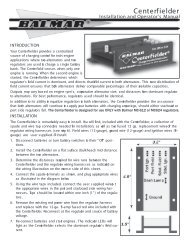
R<strong>Digital</strong> <strong>Duo</strong> <strong>Charge</strong><strong>Installation</strong>/<strong>Operation</strong>© Revised July, 2011IntroductionThe <strong>Digital</strong> <strong>Duo</strong> <strong>Charge</strong> provides a safe, intelligent alternative for the care of your vessel’s engine starting battery. Unlikeswitches, isolators and other charge splitting devices, the <strong>Duo</strong> <strong>Charge</strong> is mounted between the vessel’s house and startingbatteries rather than between the alternator and batteries. This allows the alternator and regulator to concentrate outputbased on the house battery’s needs. When the <strong>Duo</strong> <strong>Charge</strong> senses charging voltage at the house battery, it works like a DCto-DCbattery charger, providing up to 30 amps of regulated charging current to support the starting battery.In most installations, the <strong>Duo</strong> <strong>Charge</strong> requires just four wires for operation; a fused input wire, a fused output wire, a groundwire and an ON/OFF wire. In applications where the <strong>Duo</strong> <strong>Charge</strong> is used to supply a battery bank that may require morethan 30 amps of regulated charging current, the <strong>Duo</strong> <strong>Charge</strong> may be used to manually control an external solenoid. Pleasenote the section in the manual relating to solenoid control.The <strong>Duo</strong> <strong>Charge</strong> is designed specifically to enable its user to control charging voltage output -- making it possible tosafely mix house and starting battery technologies. The <strong>Duo</strong> <strong>Charge</strong> features four different programs based on four batterytechnologies: Standard Flooded, Deep Cycle Flooded, Gel and AGM battery types. In addition, the <strong>Duo</strong> <strong>Charge</strong> can beprogrammed for 12-volt or 24-volt operation. When used with an optional Battery Temperature Sensor cable (MC-TS-B), the<strong>Duo</strong> <strong>Charge</strong> responds to a battery over-temperature condition by automatically discontinuing charging output.Safety ConsiderationsBefore installing your <strong>Duo</strong> <strong>Charge</strong>, please take a moment to consider these guidelines for safe regulator installation. Failureto work safely could result in injury or damage to your electrical system.1. Always disconnect your battery banks and ensure that switches are “OFF” prior to installing your regulator.2. Remove loose-fitting clothing or jewelry, which could become entangled in your motor or other machinery.3. Wear ANSI-approved safety glasses.4. DO NOT attempt to modify the <strong>Duo</strong> <strong>Charge</strong>. Alterations could result in damage to your charging system, and will voidyour warranty.5. Do not attempt installation if tired or fatigued.6. Ensure the engine has cooled before initiating installation.7. Do not attempt installation while using alcohol or medication that could impair your judgment or reaction time.8. Always use the right tool for the job. Improper tool use may damage regulator or your boat, and could result in personalinjury.9. Take time to read the manual. Equipment damage and possible injuries may result from an incomplete understandingof the installation and operation of the <strong>Duo</strong> <strong>Charge</strong>. If you are unfamiliar with DC electrical systems, consult with alicensed marine electrician.Introduction.............................................................................1Safety Considerations............................................................1Unpacking The Box.................................................................2<strong>Installation</strong> Basics...................................................................2Wiring Basics/Ground Wire/Output Wire............................2Input Wire/ON-OFF Wire/Optional Connections...............3Battery Temperature Sensor/Solenoid Drive.....................4<strong>Duo</strong> <strong>Charge</strong> <strong>Operation</strong>...........................................................5Contents1Programming <strong>Duo</strong> <strong>Charge</strong>/System Voltage......................6Programming For Battery Type...........................................6Programming Lower/Upper Voltage Limits......................7Troubleshooting.....................................................................8<strong>Duo</strong> <strong>Charge</strong> Wiring Diagram................................................8<strong>Duo</strong> <strong>Charge</strong> Terminal Location Legend.............................9<strong>Balmar</strong> Contact Information................................................9
Unpacking The BoxPrior to installing the <strong>Duo</strong> <strong>Charge</strong>, we recommend that you inventory the contents of the packaging and ensure that the followingitems are included. Contact <strong>Balmar</strong> Customer Service at 360-435-6100 if any items listed below are missing.• <strong>Digital</strong> <strong>Duo</strong> <strong>Charge</strong>• Input Cable (Includes two ring terminal connectors and 30-amp ATC fuse and fuseholder)• Output Cable (includes one ring terminal and one butt connector, with a 30-amp ATC fuse and fuseholder)• Programming screwdriver (magnetic tip at end of screwdriver handle is used for programming, not the blade end)• Instructional manual<strong>Installation</strong> BasicsThe <strong>Duo</strong> <strong>Charge</strong> MUST be mounted within the length of the Input Cable from the house battery. Four mounting holes areincluded on the mounting tabs of the <strong>Duo</strong> <strong>Charge</strong>. Ensure that the mounting location is protected from moisture and temperaturesin excess of 120º F. The <strong>Duo</strong> <strong>Charge</strong> should be installed far enough from inverters, navigational, and communicationsequipment to ensure protection from radio frequency noise. The location of the <strong>Duo</strong> <strong>Charge</strong> should make it possible toeasily view its LED display. The short length of the Input Cable and longer Output Cable allow the wiring to act like an electricspring, enabling the <strong>Duo</strong> <strong>Charge</strong> to address high battery loads more efficiently.Wiring BasicsOnce installed as described above, the <strong>Duo</strong> <strong>Charge</strong> can be wired for proper operation. The following sections will describethe recommended connection points for optimal charging performance. The four following connections are required.Ground WireThe <strong>Duo</strong> <strong>Charge</strong> must be properly connected to system ground, which must be shared between the house and starting batterybanks, for proper operation. Failure to do so will result in non-operation and potential damage to the device. Connectionto system ground can be made at one of the following: house battery negative post, starting battery negative post, or systemground bus. User-supplied 14-gauge wire is recommended. To install the ground wire:1. Select a length of 14-gauge wire long enough to extend from the Ground Terminalon the <strong>Duo</strong> <strong>Charge</strong> to your intended ground source, such as a ground bus as shownat right.2. Crimp appropriately-sized ring terminal and 1/4” female spade connector to thewire ends.3. Connect the female spade terminal to the Ground Terminalon the <strong>Duo</strong> <strong>Charge</strong>.4. Connect the ring terminal to the desired ground source.Output CableThe <strong>Duo</strong> <strong>Charge</strong> includes a 30-amp, fused 10-gauge cable withone ring terminal and a butt connector terminal. The installermust supply the length of 10-gauge wire required to extend to the starting battery from thebutt connector end of the Output Cable. A minimum run of eight feet of wire from the OutputCable to the starting battery is recommended. Again, the reason for the extra wire lengthis to act like an electic spring which allows the <strong>Duo</strong> <strong>Charge</strong> to produce a higher current. Toinstall the Output Cable:1. Attach the Output Cable’s ring terminal to the starting battery positive post.2. Determine the correct length of 10-gauge wire to extend from the Output Cable to the<strong>Duo</strong> <strong>Charge</strong>. Connect at the butt connector. Attach a ring terminal connector at the end ofthe 10-gauge wire and connect to the <strong>Duo</strong> <strong>Charge</strong> output terminal.2
Input CableThe <strong>Duo</strong> <strong>Charge</strong> includes a 30-amp, fused 10-gauge cable with two ring terminals. To install the Input Cable:1. Connect the larger of the two ring terminal connections to the positive post of your house battery. Most marine batterieswill include a secondary stud on the battery lug that will provide a satisfactory connection point.2. Connect the smaller of the two ring terminal connections to the input terminal of the <strong>Duo</strong> <strong>Charge</strong>.While it may be more convenient to mount the <strong>Duo</strong> <strong>Charge</strong> a further distance than is allowed by the length of the InputCable, we strongly recommend limiting that distance to the length provided. Again, the shorter length of the input wireallows for a longer run of the output side of the <strong>Duo</strong> <strong>Charge</strong> wiring to add greater ability to address larger loads.ON/OFF WireThe fourth and final wire required for basic operation is the ON/OFF wire, which supplies either switched or constant powerto the <strong>Duo</strong> <strong>Charge</strong>. If automatic activation of the <strong>Duo</strong> <strong>Charge</strong> is desired whenever a source of charging is available at thehouse battery bank, the ON/OFF wire can be connected directly to the positive post of the house battery or at the Inputterminal of the <strong>Duo</strong> <strong>Charge</strong> (as shown in diagram at right).When connected directly to house battery voltage, the <strong>Duo</strong> <strong>Charge</strong> will remain in a sleep mode whenever input voltageremains below 13 volts in a 12-volt charging system, or 26 volts in a 24-volt charging system. When voltage at the Inputterminal exceeds that voltage threshold, the <strong>Duo</strong> <strong>Charge</strong> will provide charging current to the starting battery. When usedin this mode, the <strong>Duo</strong> <strong>Charge</strong> will require a nominal amount of current while asleep (approximately 500mA). If the vesselremains disconnected from a charge source for an extended period, the <strong>Duo</strong> <strong>Charge</strong> can be disabled by disconnecting theON/OFF wire from the ON/OFF terminal, or by installing and using an ON/OFF toggle in the ON/OFF wire.If the <strong>Duo</strong> <strong>Charge</strong> is only intended for use when the house battery is being charged bythe alternator and regulator, the ON/OFF wire can be connected to the same switchedvoltage source that’s used to supply the voltage regulator’s ignition circuit. To installthe ON/OFF wire:1. Determine the preferred method for <strong>Duo</strong> <strong>Charge</strong> activation, and the preferredsource for ON/OFF voltage.2. Provide a length of 14-gauge wire suitable for the intended voltage source and the<strong>Duo</strong> <strong>Charge</strong>.3. Attach one appropriately sized ring terminal or other suitable termination connector,and a 1/4” female spade connector to the ends of the wire.4. Plug the 1/4” spade terminal onto the <strong>Duo</strong> <strong>Charge</strong>’s ON/OFF connector pin.5. Connect the other end of the wire, as required, to the desired source of ON/OFFvoltage.Optional Wiring ConnectionsWhile the <strong>Duo</strong> <strong>Charge</strong> does provide full functionality with the basic four-wire connections discussed above, there are anumber of optional functions which may provide additional capacity or intelligence. These include battery temperaturesensing and solenoid control, which enables the manual bypass of the <strong>Duo</strong> <strong>Charge</strong>’s internal circuitry and activation of asolenoid drive circuit that can be used in conjunction with a higher capacity solenoid relay.3
Battery Temperature SensorWhen used in conjunction with the optional MC-TS-B Battery Temperature Sensor, the <strong>Duo</strong> <strong>Charge</strong> can automatically respondto a potential battery thermal runaway by discontinuing charging output to the starting battery — adding a level ofsafety to the charging system. To install the MC-TS-B Battery Temperature Sensor:1. Attach the lug that houses the sensor module to the negative post of the starting battery.2. Using care to match polarity between the temperature sensor positive and negative wires and the positive and negativetemperature sensor terminal pins on the <strong>Duo</strong> <strong>Charge</strong>, connect wires to the terminal pins.Solenoid DriveIn applications where the <strong>Duo</strong> <strong>Charge</strong> is used to support larger capacity starting batteries (such as 4D and 8D models) orwindlass and/or thruster batteries, there may be instances when the 30-amp capacity of the <strong>Duo</strong> <strong>Charge</strong>’s circuitry may notprovide sufficient current to satisfy demands. When used as a stand alone charge source, the <strong>Duo</strong> <strong>Charge</strong> is designed todiscontinue charging when demands exceed its capabilities. At that point, the <strong>Duo</strong> <strong>Charge</strong> will wait for a short period andquery if the demand has diminished to below its 30-amp capacity. If so, the <strong>Duo</strong> <strong>Charge</strong> will continue charging. If demandcontinues to exceed capacity, the <strong>Duo</strong> <strong>Charge</strong> will continue to shut down, while checking periodically to see if demand hasdiminished.If your application requires frequent charging levels in excess of 30 amps, it may be necessary to add a solenoid as a methodto manually bypass the <strong>Duo</strong> <strong>Charge</strong>’s internal circuitry. Keep in mind, the <strong>Duo</strong> <strong>Charge</strong> will not automatically activate the solenoidif the demand exceeds its capacity. As such, it is important to monitor charging voltage closely at the battery beingcharged by the <strong>Duo</strong> <strong>Charge</strong>. To utilize the <strong>Duo</strong> <strong>Charge</strong>’s solenoid drive function, it will be necessary for the user to supply anappropriate-capacity solenoid and a toggle or other ON/OFFswitching mechanism to control the bypass func tion.To install the external solenoid control circuit:1. Install solenoid between primary and secondary batterybanks. Ensure that solenoid is properly sized to handlemaximum current flow. Ensure that wire gauge is adequateto supply maximum current flow.2. Connect positive solenoid relay terminal to a source ofpositive system voltage.3. Connect the negative solenoid relay to the Solenoid Driveterminal on the <strong>Duo</strong> <strong>Charge</strong>.4. Create a switched circuit between system ground and theAuto/Manual terminal on the <strong>Duo</strong> <strong>Charge</strong>.Once installed, the <strong>Duo</strong> <strong>Charge</strong> will be in the Auto modewhenever the toggle switch is in the OFF position, and chargingwill occur via the <strong>Duo</strong> <strong>Charge</strong>’s internal circuitry. When thetoggle switch is in the ON position, the <strong>Duo</strong> <strong>Charge</strong> will revertto manual mode, allowing the solenoid to control charge flowto the secondary battery bank.4
<strong>Duo</strong> <strong>Charge</strong> <strong>Operation</strong>When the four required wires are connected to the <strong>Duo</strong> <strong>Charge</strong>, a start-up sequence will initiate on the <strong>Duo</strong> <strong>Charge</strong>’s six colorcodedLED display. When powered up, the LEDs will:1. Illuminate from right to left (amber to green) four times, indicating that the <strong>Duo</strong> <strong>Charge</strong> is set for 12-volt operation.2. Illuminate the #1 and #2 amber LEDs, followed by a green LED, indicating battery program type. The #3 green indicatesStandard Flooded; the #4 green indicates Deep Cycle Flooded; the #5 green indicates gel; and the #6 green indicatesAGM.3. Illuminate the #1 amber, followed by a combination of green LEDs, indicating low voltage activation. See the <strong>Balmar</strong> <strong>Duo</strong><strong>Charge</strong> web page for detailed values for low and high voltage settings.4. Illuminate the #2 amber, followed by a combination of green LEDs, indicatingmaximum voltage ouput.5. Illuminate the #3 green LED, indicating that the <strong>Duo</strong> <strong>Charge</strong> is in operation.If, upon start up, the <strong>Duo</strong> <strong>Charge</strong> display deviates from the sequence above, orif the #3 LED begins to blink, proceed to the troubleshooting instructions.The <strong>Duo</strong> <strong>Charge</strong> performs like a DC to DC battery charger. When the <strong>Duo</strong><strong>Charge</strong> recognizes 13 volt or greater on the input terminal the <strong>Duo</strong> <strong>Charge</strong> willturn on and start passing current to the start battery.The maximum output amperage of the <strong>Duo</strong> <strong>Charge</strong> is 30 amps. When used asa stand alone charge source, the <strong>Duo</strong> <strong>Charge</strong> is designed to discontinue chargingwhen demands exceed its capabilities. At that point, the <strong>Duo</strong> <strong>Charge</strong> willwait for a short period and query if the demand has diminished to below its30-amp capacity. If so, the <strong>Duo</strong> <strong>Charge</strong> will continue charging. If demand continuesto exceed capacity, the <strong>Duo</strong> <strong>Charge</strong> will continue to shut down, whilechecking periodically to see if demand has diminished. So, if you decided toinstall the <strong>Duo</strong> <strong>Charge</strong> to charge a bow thruster battery, windlass battery or abattery that can be highly discharged the <strong>Duo</strong> <strong>Charge</strong> may go into the overcurrent condition because the demand is greater than 30 amps. If you intendto use the <strong>Duo</strong> <strong>Charge</strong> to support charging at a larger battery with demandsgreater than a typical starting battery, please contact <strong>Balmar</strong> Customer Serviceat 360-435-6100 for technical support.If your application requires frequent charging levels in excess of 30 amps, it may be necessary to add a solenoid as a methodto manually bypass the <strong>Duo</strong> <strong>Charge</strong>’s internal circuitry. Keep in mind, the <strong>Duo</strong> <strong>Charge</strong> will not automatically activate the solenoidif the demand exceeds its capacity. As such, it is important to monitor charging voltage closely at the battery beingcharged by the <strong>Duo</strong> <strong>Charge</strong>.To utilize the <strong>Duo</strong> <strong>Charge</strong>’s solenoid drive function, it will be necessary for the user to supply an appropriate-capacity solenoidand a toggle or other ON/OFF switching mechanism to control the bypass function.NOTES:5
Programming The <strong>Duo</strong> <strong>Charge</strong>The <strong>Duo</strong> <strong>Charge</strong> features four selectable program types for the following battery types: standard flooded, deep cycle flooded,gel and absorbed glass mat (AGM). Program changes are made by activating a magnetic reed switch located on the <strong>Duo</strong><strong>Charge</strong> circuit board with the magnetic tipped programming tool provided. In addition to battery type, the <strong>Duo</strong> <strong>Charge</strong>can be programmed to support 12-volt or 24-volt charging systems.Programming For System Voltage - 12 to 24-VoltThe <strong>Duo</strong> <strong>Charge</strong> is preset at the factory for 12-volt operation. To adjust the <strong>Duo</strong> <strong>Charge</strong> for 24-volt charging:1. Remove the wire supplying the ON/OFF terminal from the ON/OFF pin.2. Place the magnetic end of the programming screwdriver on the RED dot (or against one or the other end of the reedswitch).3. Reconnect the wire to the ON/OFF terminal while continuing to hold the magnet against the RED dot. After a coupleof seconds, the #3 green LED will illuminate.. Continue to hold the magnet to the switch.4. After a few additional seconds, the #3 green and #4 green will both illuminate. Remove the magnet from the switch.Wait until the green LEDs go dark.5. After saving the program change, the display will indicate 24-volt mode by scrolling from left to right (green to amber)at start up.Programming For System Voltage - 24 to 12-Volt1. Remove the wire supplying the ON/OFF terminal from the ON/OFF pin.2. Place the magnetic end of the programming screwdriver on the RED dot (or against one or the other end of the reedswitch).3. Reconnect the wire to the ON/OFF terminal while continuing to activate the reed switch with the magnet. After acouple of seconds, the #3 green LED will illuminate.. Continue to hold the magnet to the switch.4. After another couple of seconds, the #3 green and #4 green will both be illuminated. Remove the magnet from theswitch. Wait until the green LEDs go dark.5. Re-activate and hold the magnet to the switch. After a couple of seconds, the #3 green LED will illuminate. Continueto hold. After several seconds, the #3 green and #5 green LEDs will illuminate. Release the magnet. After saving theprogram change, the display will indicate 12-volt mode by scrolling from right to left (amber to green) at start up.Programming For Battery TypeThe <strong>Duo</strong> <strong>Charge</strong>’s factory default program is suitable, right out of the box, for the majority of cranking-type batteries – andwill require no programming after installation. Some technologies, however, may benefit from some voltage adjustment.Four programs, based on standard flooded, deep cycle flooded, gel and AGM battery types are included in the <strong>Duo</strong> <strong>Charge</strong>’sprogramming mode. To select the program that’s best suited to your battery type:1. Ensure that the #3 green LED is illuminated. Place the magnetic end of the programming screwdriver on the RED dot(or against one or the other end of the reed switch).2. Continue to hold the magnet against the switch. After several seconds, the #3 green LED will go dark, and the #1 and#2 amber LEDs will illuminate.3. Continue to hold the magnet against the switch. After several seconds, the #1 and #2 amber and the #3 LEDs will beilluminated.4. Continue to hold the magnet to the switch. After a few more seconds, the #3 green light will go dark and the next greenLED will illuminate.5. When the green LED indicating your desired battery type is illuminated, release the switch by removing the magnet.6. Should you need to change the programming selection,activate and hold the switch until the #1and #2 amber and #6 green LEDs are illuminated.Release the switch until the LEDs go dark. Reactivatethe switch. The LEDs will illuminate, andthe green LEDs will scroll the opposite direction.6
Programming Lower And Upper Voltage LimitsIn addition to its ability to be programmed for specific battery type, the <strong>Digital</strong> <strong>Duo</strong> <strong>Charge</strong> offers the ability to adjust the upper andlower voltage limits for charging, enabling the <strong>Duo</strong> <strong>Charge</strong> to be used with battery types not included in the four selectable presetprograms.To program the lower voltage limit:1. With the <strong>Duo</strong> <strong>Charge</strong> powered up, place the magnetic end of the programming screwdriver against the RED dot on the epoxypotting (or against one or the other end of the reed switch). The #1 and #2 Amber LEDs will illuminate, followed by the #3 greenLED.2. Release the magnet from the RED dot. Once the reed switch is disengaged, the LEDs will go dark. Shortly thereafter, the #1Amber LED will illuminate.3. Re-activate the switch by returning the magnetic screwdriver to the RED dot.4. The 1# Amber LED will be joined by a number of sequenced Green LEDs as described in the chart below. Release the magnetfrom the switch when the desired value is indicated.5. The 1# Amber LED will re-illuminate, followed by the #2 Amber LED.6. If you choose to select the upper voltage value, continue to the following instructions.To program the lower voltage limit:7. Re-activate the switch by returning the magnetic screwdriver to the RED dot when the #2 Amber LED is illuminated.8. The 2# Amber LED will be joined by a number of sequenced Green LEDs as described in the chart below. Release the magnetfrom the switch when the desired value is indicated.9. The 2# Amber LED will re-illuminate, allowing you to change your programming choice, if needed.10. If the reed switch is not re-activated, the display will cycle between the #1 and #2 Amber LEDs two more times. Both #1 and #2LEDs will flash together a total of eight times, indicating that your program choices have been saved.
<strong>Duo</strong> <strong>Charge</strong> TroubleshootingSymptomNo Lights/No OutputInterference at radio,autopilot or navigationequipment when <strong>Duo</strong><strong>Charge</strong> is activeOutput voltage is not appropriatefor battery typeselectedNo Output. #4 LED blinksonce intermittentNo Output. #4 LED blinkstwice intermittentNo Output. #4 LED blinksthree times intermittentNo Output. #4 LED blinksfour times intermittentNo Output. #4 LED blinksfive times intermittentCause/Solution1.2.3.4.5.1.2.3.4.1.2.3.4.1.1.1.2.1.1.2.3.No voltage at input wire or ON/OFF wire – Check wiring and repair.Bad fusing on input wire – Replace 30A fuse in input cable.Voltage too low at house battery bank – Check house battery charging system.Starting battery demanding >30A – Install solenoid and manual over-ride switch. Check grounding.Bad <strong>Duo</strong> <strong>Charge</strong> unit – Contact <strong>Balmar</strong> Customer Service at 360-435-6100 or at balmar@balmar.net.Input, Output or ON/OFF wires causing interference – Re-route wiring. Check system grounding.Output wire is coiled – Uncoil any surplus wire and re-arrange to ensure noise is reduced.<strong>Duo</strong> <strong>Charge</strong> is mounted too close to electronics – Relocate <strong>Duo</strong> <strong>Charge</strong>.Frequency interference – Install noise reduction filter on electronics power wire.Wrong battery program selected – Verify program and re-program as described above.Voltage drop in output cable – Check wiring resistance and repair as needed.Voltage drop in input cable – Check wiring resistance and repair as needed.Voltage drop in output cable – Check wiring resistance and repair as needed.High system temperature – Determine source of overheating and repair.Start battery voltage too high – Inspect starting battery for secondary charge sources and correct.House battery voltage too low – Correct charging source for house battery bank.House battery voltage too low – Check wiring resistance in Input wire and repair as needed.House battery voltage too high – Correct charging source for house battery bank.Start battery temperature too high – Shut down system. CAREFULLY inspect starting battery for signs ofoverheating. Repair condition and/or replace starting battery.Bad Temperature Sensor cable – Check wiring resistance (approx. 34-40k). Repair or replace TemperatureSensor cable.Bad system grounding – Test ground-side resistance between batteries and charging system. Repair.No Output. #4 LED blinkssix times intermittent1. Voltage too low at ON/OFF terminal – Repair or relocate ON/OFF wire.<strong>Balmar</strong> warrants the <strong>Digital</strong> <strong>Duo</strong> <strong>Charge</strong> for one year against defects in material or worksmanship. The complete <strong>Balmar</strong> limited productwarranty statement is available at www.balmar.net. Please contact our Customer Service department at 360-435-6100 prior to return forwarranty evaluation. <strong>Balmar</strong> is not responsible for product returned without prior authorization. See website for detailed warranty info.<strong>Duo</strong> <strong>Charge</strong> Wiring DiagramThe following diagram illustrates a typical <strong>Duo</strong> <strong>Charge</strong> installation.Please note that the use of a separate solenoid and manual bypass isonly required in installations where the 30-amp limitation of the <strong>Duo</strong><strong>Charge</strong>’s internal circuitry is unable to support starting battery loads.The optional Battery Temperature Sensor cable allows the <strong>Duo</strong> <strong>Charge</strong>to monitor for unsafe temperatures at the starting battery, as is recommendedas an additional measure of safety.7
<strong>Duo</strong> <strong>Charge</strong> Terminal Locations1. Input Terminal - Connects to the positive terminal of the housebattery via the battery input cable supplied. THIS TERMINAL CON-NECTION MUST BE INSTALLED.2. Output Terminal - Connects to the positive terminal of the startingbattery via the battery output cable supplied. THIS TERMINALCONNECTION MUST BE INSTALLED.3. Magnetic Reed Switch - Used to program the <strong>Duo</strong> <strong>Charge</strong> for systemvoltage and battery type. A small screwdriver with a magnetat the end of the handle is provided for programming control.4. Ground Terminal - Connects to system ground via a user-supplied14-gauge wire. THIS TERMINAL CONNECTION MUST BE IN-STALLED.5. Temperature Sensor (Negative) - Used in conjunction with the MC-TS-B Battery Temperature Sensor. Connect sensor’s BLACK wire tothis terminal.6. Temperature Sensor (Positive) - Used in conjunction with the MC-TS-B Battery Temperature Sensor. Connect sensor’s RED wire tothis terminal.7. Auto/Manual Control (Negative) - Optional wiring connection allowsthe <strong>Duo</strong> <strong>Charge</strong> user to bypass the internal circuitry and supplya negative source to a solenoid relay via the <strong>Duo</strong> <strong>Charge</strong>’s SolenoidDrive (#9). This option is used in cases where larger batterybanks (such as thruster or windlass banks) may require a chargesource exceeding the <strong>Duo</strong> <strong>Charge</strong>’s 30-amp maximum output.This function is only required when a separate solenoid is used. Toutilize this function: connect the terminal to system ground via a14-gauge wire with an ON/OFF toggle inline.8. ON/OFF Control (Positive) - The ON/OFF terminal provides thevoltage that activates the <strong>Duo</strong> <strong>Charge</strong>. THIS TERMINAL CONNEC-TION MUST BE INSTALLED.9.Solenoid Drive (Negative) - Provides a connection to ground whenterminal #7 completes a pathway to ground.All information contained is assumed to be correct and accurate at time of publication. Ballard CommercialIndustries, Inc. and its employees assume no liability for damage or injury as a result of the use of this productor its documentation. No portion of this documentation may be copied or reprinted without expresspermission from Ballard Commercial Industries, Inc.©2008 Ballard Commercial Industries, Inc.18930 59th Ave. NE, Arlington, WA 98223Phone: 360-435-6100, Fax: 360-435-3210, Email: balmar@balmar.net8