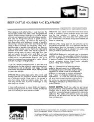
Short Portable Self-supporting Wall Leaflet
Short Portable Self-supporting Wall Leaflet
Short Portable Self-supporting Wall Leaflet

You also want an ePaper? Increase the reach of your titles
YUMPU automatically turns print PDFs into web optimized ePapers that Google loves.
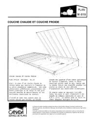
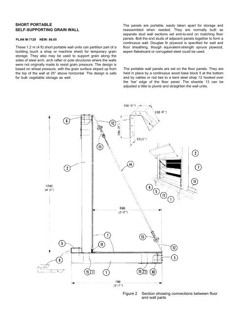
Grain pressure on the 'floor' part holds each panel in place.When panels are first set up, it is helpful to brace themtemporarily with pieces of wood tacked to the wall and floor.Figure 1 shows a perspective of the wall and corner sections.These units are framed with No. 2 S-P-F lumber and coveredwith Douglas fir plywood exterior sheathing with the face grainlaid across the floor joists and wall studs.Figure 2 shows the critical dimensions, the fastenings, thetie-down hardware and the end cap board 3 which makes thefloor sleepers load-sharing.Figure 3 gives the floor plans for a wall and a corner unit,showing the location of the studs, floor joists and corner wallblockings. Steel strap ties and steel joist hangers arehammer-bent to a tight tit and nailed in place wherever criticalconnections are required.1 38 x 89 mm (2x4) floor joists at 400 mm(16 in.) oc2 38 x 89 mm (2x4) studs at 400 mm (16 in.)oc, notched for 113 38 x 89 mm (2x4) end cap4 38 x 89 mm (2x4) blocking (at corner wallonly)5 38 x 89 mm (2x4) base block6 38 x 89 mm (2x4) plate7 9.5 mm (3/8 in.) exterior sheathingDouglas fir plywood or material withequivalent strength in bending8 0.9 x50 x300 mm (20 ga x 2 x 12 in.) galvsteel strap9 0.9 x 100 x 300 mm (20 ga. x 4 x 12 in.)galv steel strap10 galv. steel joist hangars11 3 x 38 x 38 mm (1/8 x 1½ x 1½ in.) steelangle, to prevent grain leakage12 steel strap, 4.8 x 50 x 450 mm (3/16 x 2 x18 in.), bend to suit at top and bottom13 shackle made from 2 - 4.8 x 38 x 100 mm(3/16 x 1½ x 4 in.) steel straps welded toM10 (3/8 in.) nut (tap end) and 14(bottom end), drill through for M10 (3/8 in.)machine bolt14 9.5 (3/8 in.) steel rod, thread top endfor 13; OR turnbuckle with closed eyes,steel cable, clamps and thimbles ratedsafe to 5 kN (1100 lb),15 4.5 x 75 mm concrete nails, numberindicated thus 316 2 - M12 x 100 mm (½ x 4 in.) machinebolts, nuts and washers17 OPTIONAL unloading port; cut plywoodopening smaller than space betweenstuds to stop the removable louver boardsFigure 3Floor plan of wall and corner units