600346027 DTW Dometic discharge pump manual - Waeco
600346027 DTW Dometic discharge pump manual - Waeco
600346027 DTW Dometic discharge pump manual - Waeco
Create successful ePaper yourself
Turn your PDF publications into a flip-book with our unique Google optimized e-Paper software.
Installation<br />
6.2 Replacing macerator <strong>discharge</strong> <strong>pump</strong><br />
6<br />
<strong>Dometic</strong> Waste Discharge Pump<br />
a vertical loop in the sanitation hose between the tank outlet and <strong>pump</strong> inlet that extends above the<br />
holding tank .<br />
2. Insert 38 mm ID duckbill valve in open end of <strong>pump</strong> body, and tighten valve nipple into <strong>pump</strong> body<br />
with counter-clockwise motion (fig . 4<br />
, page 2) .<br />
3 . In the four mounting feet locations on <strong>pump</strong> base (fig . 4 1, page 2), use 6 mm (#12) minimum diameter<br />
fasteners with 19 mm (0 .75 in .) maximum diameter washer to fasten <strong>pump</strong> to surface .<br />
4. Apply small amount of liquid dishwashing detergent or <strong>Dometic</strong> hose lubricant (not supplied with<br />
<strong>pump</strong>) around ends of <strong>pump</strong> inlet and <strong>discharge</strong> fittings and inside ends of 38 mm ID sanitation hose<br />
that will attach to these fittings .<br />
5 . Slip two hose clamps (not supplied) over each end of hose that attaches to <strong>pump</strong> . Push hose ends<br />
onto <strong>pump</strong> fittings and position the clamps screws so that they are 180° apart from each other .<br />
Tighten hose clamps to <strong>pump</strong> fittings (fig . 5 , page 2) .<br />
6 . With electrical power off, make proper wiring connections according to wiring diagram (fig . 3 , page<br />
2) . With <strong>pump</strong> switch in “off” position, if applicable, turn on electrical power .<br />
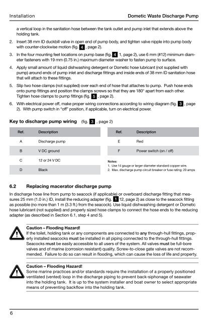
Key to <strong>discharge</strong> <strong>pump</strong> wiring (fig . 3 , page 2)<br />
Ref. Description<br />
A Discharge <strong>pump</strong><br />
B V DC ground<br />
C 12 or 24 V DC<br />
D Black<br />
Ref. Description<br />
E Red<br />
F Power switch (on / off)<br />
Notes:<br />
1. Use 14 gauge or larger diameter standard copper wire.<br />
2 . Max . <strong>discharge</strong> <strong>pump</strong> circuit breaker or fuse rating: 20 amps<br />
In <strong>discharge</strong> hose line from <strong>pump</strong> to seacock (if applicable) or overboard <strong>discharge</strong> fitting that measures<br />
25 mm (1.0 in.) ID, install the reducing adapter (fig. 1 12, page 2) as close to the seacock fitting<br />
as possible (no more than 1 m (3.3 ft.) from the seacock). Use liquid dishwashing detergent or <strong>Dometic</strong><br />
hose lubricant (not supplied) and properly sized hose clamps to connect the hose ends to the reducing<br />
adapter (as described in Section 6 .1, step 4 and 5) .<br />
Caution – Flooding Hazard!<br />
If the toilet, holding tank or any components are connected to any through-hull fittings, properly<br />
installed seacocks must be installed in all piping connected to the through-hull fittings .<br />
Seacocks must be easily accessible to all users of the system . All valves must be full-bore<br />
valves and of marine (corrosion resistant) quality. Screw-to-close gate valves are not recommended.<br />
Failure to do so can result in flooding, which can cause the loss of life and property.<br />
Caution – Flooding Hazard!<br />
Some marine practices and/or standards require the installation of a properly positioned<br />
ventilated (vented) loop in the <strong>discharge</strong> piping to prevent back-siphonage of seawater<br />
into the holding tank . It is up to the system installer and boat owner to select appropriate<br />
means of preventing backflow into the holding tank.


