manual de instalação da unidade de ar condicionado tipo split ...
manual de instalação da unidade de ar condicionado tipo split ...
manual de instalação da unidade de ar condicionado tipo split ...

Create successful ePaper yourself
Turn your PDF publications into a flip-book with our unique Google optimized e-Paper software.
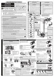
A 100 mm DA UNIDADE<br />
APENAS PARA TÉCNICOS DE MANUTENÇÃO<br />
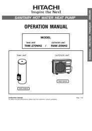
MANUAL DE INSTALAÇÃO DA UNIDADE<br />
DE AR CONDICIONADO TIPO SPLIT<br />
Uni<strong>da</strong><strong>de</strong> Interior<br />
RAK-50PPA<br />
Uni<strong>da</strong><strong>de</strong> Exterior<br />
RAC-50WPA<br />
PRECAUÇÕES DE SEGURANÇA<br />
● Leia cui<strong>da</strong>dosamente os procedimentos <strong>de</strong> instalação<br />
antes <strong>de</strong> inici<strong>ar</strong> qualquer trabalho.<br />
● O agente <strong>de</strong> ven<strong>da</strong>s <strong>de</strong>verá inform<strong>ar</strong> os clientes sobre<br />
os procedimentos <strong>de</strong> instalação correctos.<br />
Ferramentas Necessárias p<strong>ar</strong>a a Instalação<br />
● + – Chave <strong>de</strong> p<strong>ar</strong>afusos ● Fita métrica ● Faca<br />
● Serra ● Berbequim ø 65 mm ● Chave sextava<strong>da</strong><br />
( 4 mm) ● Chave inglesa (14, 17, 22, 26, 27 mm)<br />
● Detector <strong>de</strong> fugas <strong>de</strong> gás ● Corta tubos ● Mastique<br />
● Fita isoladora ● Alicate ● Mandril<br />
● Leia cui<strong>da</strong>dosamente as precauções <strong>de</strong> segurança antes <strong>de</strong> utiliz<strong>ar</strong> a uni<strong>da</strong><strong>de</strong>.<br />
● O conteúdo <strong>de</strong>sta secção é crucial p<strong>ar</strong>a assegur<strong>ar</strong> a segurança. Preste especial atenção aos símbolos seguintes.<br />
! AVISO ........ A utilização <strong>de</strong> métodos <strong>de</strong> instalação incorrectos po<strong>de</strong>rá caus<strong>ar</strong> morte ou<br />
ferimentos graves.<br />
! CUIDADO ......... A instalação incorrecta po<strong>de</strong>rá origin<strong>ar</strong> consequências graves.<br />
Certi que-se <strong>de</strong> que a uni<strong>da</strong><strong>de</strong> está a funcion<strong>ar</strong> correctamente após a instalação. Explique ao cliente como utiliz<strong>ar</strong> a uni<strong>da</strong><strong>de</strong>,<br />
conforme <strong>de</strong>scrito no <strong>manual</strong> do utilizador.<br />
!<br />
!<br />
AVISO<br />
● Solicite a instalação <strong>da</strong> uni<strong>da</strong><strong>de</strong> ao seu agente <strong>de</strong> ven<strong>da</strong>s ou a um técnico quali cado. Se a uni<strong>da</strong><strong>de</strong> não for instala<strong>da</strong> por<br />
um técnico qualicado, existe o risco <strong>de</strong> fuga <strong>de</strong> água, curto-circuito ou incêndio.<br />
● Durante o processo <strong>de</strong> instalação, respeite as instruções existentes no <strong>manual</strong> <strong>de</strong> instalação. A instalação incorrecta po<strong>de</strong>rá<br />
origin<strong>ar</strong> fuga <strong>de</strong> água, choque eléctrico e incêndio.<br />
● Certi que-se <strong>de</strong> que os locais seleccionados p<strong>ar</strong>a a montagem <strong>de</strong> ambas as uni<strong>da</strong><strong>de</strong>s po<strong>de</strong>m suport<strong>ar</strong> o peso integral<br />
<strong>de</strong>stas. Caso contrário, as uni<strong>da</strong><strong>de</strong>s po<strong>de</strong>rão cair e caus<strong>ar</strong> perigo.<br />
● Respeite as normas e os regulamentos locais relativos a instalações eléctricas, bem como os métodos <strong>de</strong>scritos no <strong>manual</strong><br />
<strong>de</strong> instalação, quando efectu<strong>ar</strong> a instalação eléctrica. Utilize cabos <strong>de</strong> alimentação aprovados pelas autori<strong>da</strong><strong>de</strong>s do seu país.<br />
● Certi que-se <strong>de</strong> que utiliza os cabos especicados p<strong>ar</strong>a ligação <strong>da</strong>s uni<strong>da</strong><strong>de</strong>s interior e exterior. Após inserir os condutores<br />
nos terminais, certique-se <strong>de</strong> que as ligações não têm folgas. A instalação incorrecta e a existência <strong>de</strong> folgas nos contactos<br />
po<strong>de</strong>rão caus<strong>ar</strong> sobreaquecimento e incêndio.<br />
● Utilize os componentes especicados p<strong>ar</strong>a a montagem. Caso contrário, po<strong>de</strong>rá existir o risco <strong>de</strong> que<strong>da</strong> <strong>da</strong>s uni<strong>da</strong><strong>de</strong>s, fuga<br />
<strong>de</strong> água, choque eléctrico e incêndio.<br />
● Certi que-se <strong>de</strong> que utiliza a tubagem a<strong>de</strong>qua<strong>da</strong> p<strong>ar</strong>a o R-410A. Caso contrário, po<strong>de</strong>rão ocorrer <strong>da</strong>nos nos tubos <strong>de</strong> cobre<br />
ou av<strong>ar</strong>ias.<br />
● Quando instal<strong>ar</strong> ou remover um ap<strong>ar</strong>elho <strong>de</strong> <strong>ar</strong> <strong>condicionado</strong>, utilize apenas o refrigerante especi cado (R410A); além disso,<br />
certi que-se <strong>de</strong> que o ciclo <strong>de</strong> refrigeração está isento <strong>de</strong> <strong>ar</strong> ou humi<strong>da</strong><strong>de</strong>. Caso contrário, a pressão no ciclo <strong>de</strong> refrigeração<br />
po<strong>de</strong>rá subir anormalmente e caus<strong>ar</strong> ruptura.<br />
● Ventile a área <strong>de</strong> trabalho se ocorrer uma fuga <strong>de</strong> gás refrigerante durante a montagem. O gás refrigerante po<strong>de</strong>rá torn<strong>ar</strong>se<br />
venenoso se entr<strong>ar</strong> em contacto com uma chama.<br />
● Quando a montagem estiver concluí<strong>da</strong>, certique-se <strong>de</strong> que não existem fugas <strong>de</strong> gás refrigerante. Se existir uma fuga <strong>de</strong><br />
gás refrigerante no interior <strong>da</strong> divisão, este po<strong>de</strong>rá torn<strong>ar</strong>-se venenoso ao entr<strong>ar</strong> em contacto com as chamas gera<strong>da</strong>s por<br />
um aquecedor ou outro ap<strong>ar</strong>elho <strong>de</strong> queima doméstico.<br />
● A execução <strong>de</strong> modicações não autoriza<strong>da</strong>s no ap<strong>ar</strong>elho <strong>de</strong> <strong>ar</strong> <strong>condicionado</strong> po<strong>de</strong> ser perigosa. Se ocorrer uma av<strong>ar</strong>ia,<br />
contacte um técnico <strong>de</strong> <strong>ar</strong> <strong>condicionado</strong> ou um electricista qualicado. A rep<strong>ar</strong>ação incorrecta po<strong>de</strong>rá origin<strong>ar</strong> fuga <strong>de</strong> água,<br />
choque eléctrico, incêndio, etc.<br />
CUIDADO<br />
● Tem <strong>de</strong> ser instalado um disjuntor ou fusível (16A <strong>de</strong> acção ret<strong>ar</strong><strong>da</strong><strong>da</strong>). A não instalação do disjuntor ou fusível po<strong>de</strong>rá<br />
origin<strong>ar</strong> perigo <strong>de</strong> choque eléctrico.<br />
Tem <strong>de</strong> ser instalado um interruptor principal com um intervalo <strong>de</strong> contacto superior a 3 mm na linha<br />
<strong>de</strong> alimentação p<strong>ar</strong>a a uni<strong>da</strong><strong>de</strong> exterior.<br />
● Não instale a uni<strong>da</strong><strong>de</strong> perto <strong>de</strong> um local on<strong>de</strong> exista gás inamável. A uni<strong>da</strong><strong>de</strong> exterior po<strong>de</strong>rá<br />
incendi<strong>ar</strong>-se se ocorrerem fugas <strong>de</strong> gás na sua proximi<strong>da</strong><strong>de</strong>.<br />
● Quando instal<strong>ar</strong> a mangueira <strong>de</strong> drenagem, certique-se <strong>de</strong> que a água ui livremente.<br />
● Os suportes <strong>da</strong> tubagem <strong>de</strong>verão ser montados a intervalos máximos <strong>de</strong> 1 metro.<br />
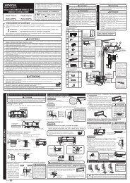
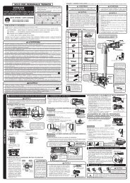
Escolha do Local <strong>de</strong> Montagem (Preste atenção às informações seguintes e obtenha a permissão do cliente antes <strong>de</strong> proce<strong>de</strong>r à instalação).<br />
! AVISO<br />
! AVISO<br />
UNIDADE INTERIOR<br />
● A uni<strong>da</strong><strong>de</strong> <strong>de</strong>ve ser monta<strong>da</strong> num local estável e isento<br />
<strong>de</strong> vibração, que possa suport<strong>ar</strong> o peso integral <strong>da</strong> uni<strong>da</strong><strong>de</strong>.<br />
!<br />
CUIDADO<br />
● Não <strong>de</strong>ve existir nenhuma fonte <strong>de</strong> calor nem obstruções perto<br />
<strong>da</strong> saí<strong>da</strong> <strong>de</strong> <strong>ar</strong>.<br />
● As distâncias <strong>da</strong>s folgas p<strong>ar</strong>a a p<strong>ar</strong>te superior, direita e esquer<strong>da</strong><br />
<strong>da</strong> uni<strong>da</strong><strong>de</strong> encontram-se especica<strong>da</strong>s na gura abaixo.<br />
● A localização tem <strong>de</strong> ser a<strong>de</strong>qua<strong>da</strong> p<strong>ar</strong>a a drenagem <strong>de</strong> água<br />
e ligação do tubo à uni<strong>da</strong><strong>de</strong> exterior.<br />
● P<strong>ar</strong>a evit<strong>ar</strong> interferências, coloque a uni<strong>da</strong><strong>de</strong> e o controlo remoto<br />
a uma distância mínima <strong>de</strong> 1 m <strong>de</strong> receptores <strong>de</strong> rádio, televisores<br />
e lâmpa<strong>da</strong>s uorescentes do <strong>tipo</strong> inversor.<br />
● P<strong>ar</strong>a evit<strong>ar</strong> erros na transmissão <strong>de</strong> sinais do controlo remoto,<br />
mantenha-o afastado <strong>de</strong> máquinas <strong>de</strong> alta frequência e sistemas<br />
<strong>de</strong> transmissão sem os <strong>de</strong> alta potência.<br />
● A altura <strong>de</strong> instalação <strong>da</strong> uni<strong>da</strong><strong>de</strong> interior <strong>de</strong>ve ser maior ou<br />
igual a 2,3 m.<br />
Nomes dos Componentes Interiores<br />
N.º<br />
Item<br />
Chapa <strong>de</strong> Montagem<br />
P<strong>ar</strong>afusos p<strong>ar</strong>a a Chapa<br />
<strong>de</strong> Montagem<br />
(4,1x32)<br />
Suporte do Controlo Remoto<br />
Pilha AAA<br />
P<strong>ar</strong>afuso p<strong>ar</strong>a o Suporte<br />
do Controlo Remoto<br />
Controlo Remoto<br />
Filtro <strong>de</strong> Puri cação do Ar<br />
Qtd<br />
Nomes dos Componentes Exteriores<br />
N.º<br />
Bucha<br />
Item<br />
Tubagem <strong>de</strong> Esgoto<br />
Bucha<br />
1<br />
6<br />
1<br />
2<br />
2<br />
1<br />
2<br />
Qtd<br />
3<br />
1<br />
1<br />
Direcção <strong>da</strong> Tubagem<br />
Ligação<br />
Existem 6 direcções permiti<strong>da</strong>s:<br />
horizontalmente <strong>de</strong> forma<br />
perpendicul<strong>ar</strong> à uni<strong>da</strong><strong>de</strong>,<br />
verticalmente a p<strong>ar</strong>tir do lado<br />
direito, horizontalmente a p<strong>ar</strong>tir<br />
do lado direito e horizontalmente<br />
a p<strong>ar</strong>tir do lado esquerdo.<br />
Não ligue a tubagem verticalmente<br />
ao lado esquerdo <strong>da</strong> uni<strong>da</strong><strong>de</strong>.<br />
Dimensões do Suporte<br />
<strong>de</strong> Montagem<br />
<strong>da</strong> uni<strong>da</strong><strong>de</strong> exterior<br />
(uni<strong>da</strong><strong>de</strong>: mm)<br />
chapa <strong>de</strong> montagem<br />
Horizontalmente<br />
perpendicul<strong>ar</strong><br />
à uni<strong>da</strong><strong>de</strong><br />
mais <strong>de</strong> 100 mm<br />
mais <strong>de</strong> 700 mm<br />
UNIDADE EXTERIOR<br />
● A uni<strong>da</strong><strong>de</strong> exterior tem <strong>de</strong> ser monta<strong>da</strong> num local que possa suport<strong>ar</strong><br />
peso elevado. Caso contrário, o ruído e vibrações aument<strong>ar</strong>ão.<br />
!<br />
CUIDADO<br />
● Não exponha a uni<strong>da</strong><strong>de</strong> directamente à luz sol<strong>ar</strong> ou à chuva. Deverá<br />
ain<strong>da</strong> existir uma boa ventilação e ausência <strong>de</strong> obstruções.<br />
● O <strong>ar</strong> que sai <strong>da</strong> uni<strong>da</strong><strong>de</strong> não <strong>de</strong>ve apont<strong>ar</strong> directamente p<strong>ar</strong>a animais ou<br />
plantas.<br />
● As folgas p<strong>ar</strong>a a p<strong>ar</strong>te superior, esquer<strong>da</strong>, direita e frontal <strong>da</strong> uni<strong>da</strong><strong>de</strong><br />
encontram-se especica<strong>da</strong>s na gura abaixo. Pelo menos 3 dos lados<br />
acima indicados têm <strong>de</strong> est<strong>ar</strong> bem ventilados.<br />
● Certi que-se <strong>de</strong> que o <strong>ar</strong> quente que sai <strong>da</strong> uni<strong>da</strong><strong>de</strong> e o ruído não<br />
perturbam os vizinhos.<br />
● Não instale a uni<strong>da</strong><strong>de</strong> num local on<strong>de</strong> exista gás inamável, vapor, óleo<br />
ou fumo.<br />
● A localização tem <strong>de</strong> ser a<strong>de</strong>qua<strong>da</strong> p<strong>ar</strong>a a drenagem <strong>da</strong> água.<br />
● Coloque a uni<strong>da</strong><strong>de</strong> interior e o cabo <strong>de</strong> ligação afastados pelo menos<br />
1 metro <strong>da</strong> antena ou <strong>da</strong> linha <strong>de</strong> sinal <strong>de</strong> televisão, rádio ou telefone.<br />
Serão assim evita<strong>da</strong>s interferências.<br />
● Não instale a uni<strong>da</strong><strong>de</strong> exterior vira<strong>da</strong> na direcção <strong>de</strong> ventos fortes.<br />
O motor do ventilador po<strong>de</strong>rá sofrer <strong>da</strong>nos.<br />
Figura que mostra a<br />
instalação <strong>da</strong> uni<strong>da</strong><strong>de</strong><br />
interior e exterior.<br />
Certi que-se<br />
<strong>de</strong> que cobre<br />
totalmente<br />
to<strong>da</strong>s as<br />
folgas com<br />
mastique.<br />
mais <strong>de</strong> 300 mm<br />
mais <strong>de</strong> 200 mm<br />
mais <strong>de</strong> 50 mm<br />
quando instala<strong>da</strong> no<br />
tecto <strong>da</strong> v<strong>ar</strong>an<strong>da</strong><br />
cerca <strong>de</strong> 400 mm<br />
não <strong>de</strong>ve dobr<strong>ar</strong><br />
Comprimento máximo do tubo 20 m<br />
Comprimento mínimo do tubo 3 m<br />
mais <strong>de</strong> 100 mm<br />
mais <strong>de</strong> 50 mm<br />
mais <strong>de</strong> 100 mm<br />
<strong>de</strong>ixe uma folga tão<br />
gran<strong>de</strong> quanto<br />
possível<br />
mais <strong>de</strong><br />
200 mm<br />
! CUIDADO<br />
No caso <strong>de</strong> o comprimento do tubo ser superior a 8<br />
m, acrescente 10 gramas <strong>de</strong> refrigerante R410A por<br />
ca<strong>da</strong> metro a mais. No entanto, o comprimento do<br />
tubo não <strong>de</strong>ve exce<strong>de</strong>r os 20 m.<br />
2.300 mm ou mais<br />
Bucha<br />
mais <strong>de</strong> 100 mm<br />
A tubagem interior <strong>de</strong>verá<br />
ser isola<strong>da</strong> com o tubo <strong>de</strong><br />
isolamento fornecido. (Se<br />
este tubo for insuficiente,<br />
utilize produtos disponíveis<br />
comercialmente).<br />
● A diferença <strong>de</strong> altura entre<br />
a uni<strong>da</strong><strong>de</strong> interior e exterior<br />
não <strong>de</strong>ve ser superior a 10<br />
metros.<br />
● O tubo <strong>de</strong> ligação tem<br />
<strong>de</strong> ser isolado com tubo<br />
<strong>de</strong> isolamento e coberto<br />
com fita isoladora,<br />
in<strong>de</strong>pen<strong>de</strong>ntemente do<br />
comprimento. (O isolamento<br />
irá <strong>de</strong>terior<strong>ar</strong>-se se não for<br />
revestido com ta isoladora).<br />
Ligação <strong>da</strong> mangueira<br />
<strong>de</strong> drenagem isola<strong>da</strong>.<br />
diâmetro interno ø 16 mm<br />
P<strong>ar</strong>a a tubagem interior, utilize<br />
mangueira <strong>de</strong> drenagem isola<strong>da</strong><br />
(disponível comercialmente).<br />
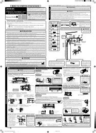
UNIDADE INTERIOR<br />
1<br />
Instalação <strong>da</strong> Chapa <strong>de</strong> Montagem, Perfuração <strong>da</strong> P<strong>ar</strong>e<strong>de</strong> e Instalação do Tubo <strong>de</strong> Protecção<br />
!<br />
CUIDADO<br />
● A drenagem do contentor <strong>de</strong> água existente <strong>de</strong>ntro <strong>da</strong> uni<strong>da</strong><strong>de</strong> interior po<strong>de</strong> ser<br />
efectua<strong>da</strong> a p<strong>ar</strong>tir do lado esquerdo. Consequentemente, a chapa <strong>de</strong> montagem<br />
tem <strong>de</strong> ser xa horizontalmente ou ligeiramente inclina<strong>da</strong> na direcção do tubo <strong>de</strong><br />
drenagem. Caso contrário, a água con<strong>de</strong>nsa<strong>da</strong> po<strong>de</strong>rá <strong>de</strong>rram<strong>ar</strong>.<br />
Montagem Directa na P<strong>ar</strong>e<strong>de</strong><br />
● Utilize as vigas ocultas na p<strong>ar</strong>e<strong>de</strong> p<strong>ar</strong>a x<strong>ar</strong> a chapa <strong>de</strong> montagem.<br />
30 mm<br />
133 mm<br />
65 mm<br />
45 mm<br />
P<strong>ar</strong>afusos p<strong>ar</strong>a a Chapa<br />
<strong>de</strong> Montagem<br />
Utilize mais<br />
<strong>de</strong> 4 p<strong>ar</strong>afusos.<br />
Perfuração <strong>da</strong> P<strong>ar</strong>e<strong>de</strong> e Instalação do Tubo <strong>de</strong> Protecção<br />
● Perfure um orifício<br />
<strong>de</strong> ø 65 mm com uma<br />
inclinação ligeira p<strong>ar</strong>a o lado<br />
exterior. Perfure a p<strong>ar</strong>e<strong>de</strong><br />
a um ângulo curto.<br />
● Corte o tubo <strong>de</strong> protecção<br />
<strong>de</strong> acordo com a espessura<br />
<strong>da</strong> p<strong>ar</strong>e<strong>de</strong>.<br />
● A folga existente no orifício<br />
<strong>de</strong> passagem do tubo<br />
<strong>de</strong> protecção <strong>de</strong>verá ser<br />
totalmente selado com<br />
mastique, p<strong>ar</strong>a impedir<br />
a entra<strong>da</strong> <strong>de</strong> água <strong>da</strong> chuva<br />
na divisão.<br />
100 mm<br />
790 mm<br />
M<strong>ar</strong>ca<br />
24 mm<br />
280 mm<br />
45 mm<br />
24 mm<br />
450 mm<br />
Linha<br />
Peso<br />
Nível<br />
! AVISO<br />
Chapa <strong>de</strong><br />
montagem<br />
Orifício p<strong>ar</strong>a<br />
tubo<br />
Procedimentos e Precauções <strong>de</strong> Instalação<br />
● Procedimentos p<strong>ar</strong>a x<strong>ar</strong> a chapa <strong>de</strong> montagem.<br />
1. Perfure o orifício 2. Coloque uma 3. Fixe a chapa <strong>de</strong> montagem<br />
na p<strong>ar</strong>e<strong>de</strong>. bucha no orifício. à p<strong>ar</strong>e<strong>de</strong> com um p<strong>ar</strong>afuso<br />
(Conforme ilustrado (Conforme ilustrado 4,1 x 32<br />
abaixo) abaixo) (Conforme mostrado na gura<br />
ø 4,8 mm<br />
P<strong>ar</strong>e<strong>de</strong><br />
ø 4,4 mm<br />
20 mm<br />
1 Chapa <strong>de</strong><br />
montagem<br />
2 P<strong>ar</strong>afuso<br />
32 mm<br />
P<strong>ar</strong>e<strong>de</strong><br />
P<strong>ar</strong>afuso 4,1 x 32<br />
● Procedimentos p<strong>ar</strong>a x<strong>ar</strong> o suporte do controlo remoto.<br />
1. Perfure o orifício na p<strong>ar</strong>e<strong>de</strong>. 2. Coloque uma bucha no orifício.<br />
(Conforme ilustrado abaixo) (Conforme ilustrado abaixo)<br />
P<strong>ar</strong>e<strong>de</strong><br />
Interior<br />
Sel<strong>ar</strong> com<br />
mastique<br />
Tubo <strong>de</strong><br />
protecção<br />
Bucha<br />
3 Suporte do<br />
Controlo<br />
Remoto<br />
PAREDE<br />
Exterior<br />
Sel<strong>ar</strong> com<br />
mastique<br />
abaixo)<br />
mais <strong>de</strong> 50 mm<br />
2 ~ 5 mm<br />
Manga do tubo<br />
<strong>de</strong> protecção<br />
5 P<strong>ar</strong>afuso<br />
Bucha<br />
Tecto<br />
Certique-se <strong>de</strong> que o cabo<br />
não está em contacto com<br />
qualquer material metálico<br />
existente na p<strong>ar</strong>e<strong>de</strong>. Utilize<br />
o tubo <strong>de</strong> protecção p<strong>ar</strong>a<br />
pass<strong>ar</strong> o cabo pela p<strong>ar</strong>e<strong>de</strong>,<br />
p<strong>ar</strong>a impedir que este seja<br />
<strong>da</strong>nicado por roedores.<br />
Certifique-se <strong>de</strong> que a<br />
selagem está <strong>de</strong>vi<strong>da</strong>mente<br />
estanque. Caso contrário,<br />
po<strong>de</strong>rá ocorrer a passagem<br />
<strong>de</strong> <strong>ar</strong> exterior com eleva<strong>da</strong><br />
percentagem <strong>de</strong> humi<strong>da</strong><strong>de</strong><br />
e a consequente que<strong>da</strong> <strong>de</strong><br />
gotículas <strong>de</strong> água.<br />
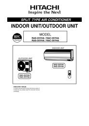
2 Instalação <strong>da</strong> Uni<strong>da</strong><strong>de</strong> Interior<br />
TUBAGEM VERTICAL<br />
Prep<strong>ar</strong>ação<br />
● Monte o cabo <strong>de</strong> ligação.<br />
● Puxe o tubo, o cabo <strong>de</strong> ligação e a mangueira <strong>de</strong> drenagem.<br />
Instalação<br />
● A p<strong>ar</strong>te superior <strong>da</strong> uni<strong>da</strong><strong>de</strong> interior é xa à chapa <strong>de</strong> montagem.<br />
● A projecção existente na p<strong>ar</strong>te inferior <strong>da</strong> uni<strong>da</strong><strong>de</strong> interior é encaixa<strong>da</strong> na chapa<br />
<strong>de</strong> montagem.<br />
Chapa <strong>de</strong> montagem<br />
Chapa <strong>de</strong> montagem<br />
Tubo <strong>de</strong><br />
Tubo <strong>de</strong> Levante o<br />
Refrigeração corpo <strong>da</strong><br />
uni<strong>da</strong><strong>de</strong> e,<br />
em segui<strong>da</strong>,<br />
empurre-o<br />
p<strong>ar</strong>a baixo.<br />
Protecção<br />
Mangueira Cabo <strong>de</strong><br />
<strong>de</strong> Drenagem Ligação<br />
TUBAGEM HORIZONTAL<br />
REMOÇÃO DA UNIDADE INTERIOR<br />
● Empurre as secções assinala<strong>da</strong>s com<br />
(PUSH) na p<strong>ar</strong>te inferior <strong>da</strong> uni<strong>da</strong><strong>de</strong> interior e<br />
puxe a placa inferior p<strong>ar</strong>a fora. Deste modo,<br />
os ganchos são libertados <strong>da</strong> placa xa.<br />
(As secções m<strong>ar</strong>ca<strong>da</strong>s com (PUSH) estão<br />
assinala<strong>da</strong>s com 2 setas na gura à direita)<br />
Projecção<br />
! CUIDADO<br />
Puxe a p<strong>ar</strong>te inferior <strong>da</strong> uni<strong>da</strong><strong>de</strong><br />
interior p<strong>ar</strong>a fora p<strong>ar</strong>a se certic<strong>ar</strong><br />
<strong>de</strong> que esta está encaixa<strong>da</strong><br />
na chapa <strong>de</strong> montagem.<br />
A instalação incorrecta po<strong>de</strong>rá<br />
origin<strong>ar</strong> vibração e ruído.<br />
Prep<strong>ar</strong>ação<br />
Procedimentos <strong>de</strong> Alteração e Instalação <strong>da</strong> Mangueira <strong>de</strong> Drenagem.<br />
● Troque a localização <strong>da</strong> mangueira <strong>de</strong> drenagem e do tampão <strong>de</strong> drenagem durante a montagem <strong>da</strong><br />
tubagem horizontal, conforme ilustrado na gura abaixo. Certique-se <strong>de</strong> que empurra a mangueira<br />
<strong>de</strong> drenagem até que o material <strong>de</strong> isolamento se dobre sobre si próprio.<br />
● Utilize um alicate p<strong>ar</strong>a pux<strong>ar</strong> o tampão <strong>de</strong> drenagem.<br />
(Este é um modo mais simples <strong>de</strong> remover o tampão <strong>de</strong> drenagem).<br />
Tampão <strong>de</strong><br />
drenagem<br />
Inserir até<br />
este ponto<br />
Tampão <strong>de</strong><br />
drenagem<br />
Mangueira<br />
<strong>de</strong> drenagem<br />
! CUIDADO A instalação incorrecta po<strong>de</strong>rá origin<strong>ar</strong> a fuga <strong>de</strong> água con<strong>de</strong>nsa<strong>da</strong>.<br />
Tubagem Horizontal e Vertical – Abertura <strong>de</strong> Orifícios<br />
● Durante a instalação <strong>da</strong> tubagem horizontal ou vertical, utilize<br />
uma faca p<strong>ar</strong>a cort<strong>ar</strong> as aberturas conforme ilustrado na<br />
gura. Em segui<strong>da</strong>, lime as extremi<strong>da</strong><strong>de</strong>s <strong>da</strong>s aberturas.<br />
Suporte<br />
dos tubos<br />
Puxe o tubo p<strong>ar</strong>a<br />
cima <strong>de</strong>pois <strong>de</strong> o<br />
dobr<strong>ar</strong> p<strong>ar</strong>a baixo<br />
Os cabos <strong>de</strong> ligação, o tubo e a<br />
mangueira <strong>de</strong> drenagem têm <strong>de</strong> ser<br />
unidos com ta isoladora.<br />
Posições <strong>da</strong>s m<strong>ar</strong>cas [Push]<br />
Mangueira <strong>de</strong> drenagem<br />
Inserir até<br />
este ponto<br />
Aberturas<br />
● Dobre os tubos enquanto segura na p<strong>ar</strong>te<br />
inferior do suporte dos tubos.<br />
MONTAGEM DOS TUBOS DE REFRIGERAÇÃO APÓS A LIGAÇÃO<br />
● Os tubos <strong>de</strong> refrigeração <strong>de</strong>vem ser ajustados <strong>de</strong> modo<br />
a caberem no orifício existente na p<strong>ar</strong>e<strong>de</strong> e, em segui<strong>da</strong>,<br />
prep<strong>ar</strong>ados p<strong>ar</strong>a a ligação.<br />
● Os terminais dos 2 tubos ligados <strong>de</strong>vem ser cobertos com<br />
isolador utilizado p<strong>ar</strong>a ligação <strong>de</strong> terminais. Em segui<strong>da</strong>,<br />
os tubos são passados por <strong>de</strong>ntro do tubo <strong>de</strong> isolamento.<br />
● Ligue o cabo <strong>de</strong> ligação <strong>de</strong>pois <strong>de</strong> remover a tampa do<br />
comp<strong>ar</strong>timento eléctrico. (Consulte “LIGAÇÃO DO CABO<br />
DE ALIMENTAÇÃO”)<br />
● Depois <strong>de</strong> efectu<strong>ar</strong> o ajustamento, coloque o cabo <strong>de</strong> ligação<br />
e os tubos no espaço disponível <strong>de</strong>baixo <strong>da</strong> uni<strong>da</strong><strong>de</strong> interior.<br />
Utilize um xador p<strong>ar</strong>a os pren<strong>de</strong>r.<br />
Suporte<br />
Tubo <strong>de</strong> isolamento (tem <strong>de</strong> ser envolvido<br />
com ta isoladora a intervalos <strong>de</strong> 120 mm).<br />
● O xador po<strong>de</strong> ser montado num dos 2 locais<br />
disponíveis. Seleccione a posição mais fácil.<br />
! CUIDADO<br />
● Não aperte <strong>de</strong>masiado o<br />
xador <strong>de</strong> borracha utilizado<br />
p<strong>ar</strong>a pren<strong>de</strong>r o isolador. Caso<br />
contrário, po<strong>de</strong>rá <strong>da</strong>ni c<strong>ar</strong> o<br />
isolamento térmico e origin<strong>ar</strong><br />
con<strong>de</strong>nsação <strong>de</strong> água.<br />
LIGAÇÃO DO TUBO DE REFRIGERAÇÃO DURANTE<br />
A INSTALAÇÃO DA UNIDADE INTERIOR<br />
Prep<strong>ar</strong>ação p<strong>ar</strong>a a Instalação dos<br />
! CUIDADO<br />
Tubos <strong>de</strong> Refrigeração<br />
● Pren<strong>da</strong> o núcleo <strong>de</strong> plástico<br />
● Una os tubos <strong>de</strong> refrigeração e o cabo <strong>de</strong> ligação.<br />
após a mandrilagem p<strong>ar</strong>a<br />
● As extremi<strong>da</strong><strong>de</strong>s dos tubos <strong>de</strong> refrigeração encontram-se nas<br />
evit<strong>ar</strong> a entra<strong>da</strong> <strong>de</strong> ap<strong>ar</strong>as <strong>de</strong><br />
localizações m<strong>ar</strong>ca<strong>da</strong>s com o símbolo “ ”.<br />
plástico nos tubos.<br />
Instalação<br />
Projecção<br />
Pendure a uni<strong>da</strong><strong>de</strong> interior na chapa <strong>de</strong> montagem. Utilize o apoio temporário<br />
existente na p<strong>ar</strong>te inferior <strong>da</strong> uni<strong>da</strong><strong>de</strong> interior p<strong>ar</strong>a a empurr<strong>ar</strong> 15 cm p<strong>ar</strong>a<br />
a frente.<br />
● Passe a mangueira <strong>de</strong> drenagem através do orifício existente na p<strong>ar</strong>e<strong>de</strong>.<br />
Gancho<br />
● Depois <strong>de</strong> lig<strong>ar</strong> o tubo <strong>de</strong> refrigeração, envolva-o com o tubo <strong>de</strong> isolamento.<br />
● Ligue o cabo <strong>de</strong> ligação <strong>de</strong>pois <strong>de</strong> remover a tampa do comp<strong>ar</strong>timento<br />
eléctrico. (Consulte “Ligação do Cabo <strong>de</strong> Alimentação”)<br />
● Depois <strong>de</strong> efectu<strong>ar</strong> o ajustamento, coloque o cabo <strong>de</strong> ligação e os tubos<br />
<strong>de</strong> refrigeração no espaço disponível <strong>de</strong>baixo <strong>da</strong> uni<strong>da</strong><strong>de</strong> interior.<br />
● A projecção existente na uni<strong>da</strong><strong>de</strong> interior tem <strong>de</strong> encaix<strong>ar</strong> na chapa<br />
cerca <strong>de</strong> 15 cm<br />
<strong>de</strong> montagem.<br />
3<br />
Tubo <strong>de</strong> isolamento térmico<br />
Tubo <strong>de</strong> refrigeração<br />
Instalação <strong>da</strong> Mangueira <strong>de</strong> Drenagem<br />
Dobragem<br />
p<strong>ar</strong>a cima<br />
!<br />
CUIDADO<br />
Cabo <strong>de</strong><br />
ligação<br />
Acumulação <strong>de</strong><br />
água con<strong>de</strong>nsa<strong>da</strong><br />
Puxe p<strong>ar</strong>a a frente<br />
p<strong>ar</strong>a facilit<strong>ar</strong> a<br />
ligação dos tubos <strong>de</strong><br />
refrigeração.<br />
Vala<br />
Dobre <strong>de</strong> modo<br />
a form<strong>ar</strong> um <strong>ar</strong>co<br />
Acumulação<br />
<strong>de</strong> água<br />
con<strong>de</strong>nsa<strong>da</strong><br />
Tubo<br />
Tubo <strong>de</strong> protecção<br />
Mangueira <strong>de</strong><br />
drenagem<br />
Cabo <strong>de</strong> ligação<br />
Mangueira<br />
<strong>de</strong> drenagem<br />
Tubo Fixador <strong>de</strong> borracha <strong>de</strong>masiado apertado<br />
Cabo <strong>de</strong> ligação<br />
Suporte<br />
Secção<br />
liga<strong>da</strong><br />
menos<br />
<strong>de</strong> 5 mm<br />
! CUIDADO<br />
Certifique-se <strong>de</strong><br />
que a mangueira<br />
<strong>de</strong> drenagem está<br />
rmemente liga<strong>da</strong> e<br />
não está dobra<strong>da</strong>.<br />
Po<strong>de</strong> escolher o lado (direito ou esquerdo) <strong>de</strong> instalação <strong>da</strong> mangueira <strong>de</strong><br />
drenagem. Durante a instalação, certique-se <strong>de</strong> que a água con<strong>de</strong>nsa<strong>da</strong> <strong>da</strong><br />
uni<strong>da</strong><strong>de</strong> interior ui livremente. (Caso contrário, po<strong>de</strong>rá ocorrer fuga <strong>de</strong> água.)<br />
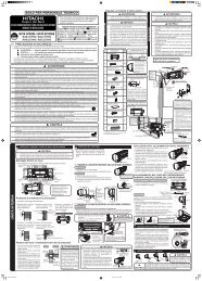
UNIDADE EXTERIOR<br />
● Monte a uni<strong>da</strong><strong>de</strong> exterior sobre uma superfície estável p<strong>ar</strong>a impedir<br />
vibrações e aumento do nível <strong>de</strong> ruído.<br />
● Deci<strong>da</strong> qual a localização <strong>da</strong> tubagem <strong>de</strong>pois <strong>de</strong> organiz<strong>ar</strong> os diferentes<br />
<strong>tipo</strong>s <strong>de</strong> tubagem disponíveis.<br />
● Quando remover a tampa lateral, puxe a pega <strong>de</strong>pois <strong>de</strong> <strong>de</strong>sencaix<strong>ar</strong><br />
o gancho puxando-a p<strong>ar</strong>a baixo.<br />
BASE<br />
Vire este lado (lado <strong>da</strong> sucção)<br />
<strong>da</strong> uni<strong>da</strong><strong>de</strong> p<strong>ar</strong>a a p<strong>ar</strong>e<strong>de</strong>.<br />
Remova a tampa lateral<br />
quando lig<strong>ar</strong> a tubagem<br />
e o cabo <strong>de</strong> ligação.<br />
Puxe p<strong>ar</strong>a baixo<br />
DRENAGEM DA ÁGUA CONDENSADA DA UNIDADE EXTERIOR<br />
● Existem orifícios na base <strong>da</strong> uni<strong>da</strong><strong>de</strong> externa p<strong>ar</strong>a escoamento <strong>da</strong><br />
água con<strong>de</strong>nsa<strong>da</strong>.<br />
● P<strong>ar</strong>a que a água con<strong>de</strong>nsa<strong>da</strong> seja escoa<strong>da</strong>, a uni<strong>da</strong><strong>de</strong> é instala<strong>da</strong> sobre um<br />
suporte ou bloco p<strong>ar</strong>a c<strong>ar</strong> 100 mm acima do solo, como é mostrado na gura.<br />
Ligue a tubagem <strong>de</strong> esgoto a um dos orifícios.<br />
● Primeiro insira uma p<strong>ar</strong>te do gancho na base (P<strong>ar</strong>te A), em segui<strong>da</strong> puxe a tubagem<br />
<strong>de</strong> esgoto na direcção indica<strong>da</strong> pela seta, inserindo simultaneamente o gancho<br />
na base. Após a instalação, verique se a tubagem <strong>de</strong> esgoto está rmemente<br />
segura na base.<br />
A<br />
100 mm ACIMA<br />
TUBAGEM<br />
BUCHA<br />
DE ESGOTO<br />
BUCHA<br />
TUBAGEM<br />
DE ESGOTO<br />
Utilização e Instalação em Zonas Frias<br />
Quando a uni<strong>da</strong><strong>de</strong> <strong>de</strong> <strong>ar</strong> <strong>condicionado</strong> é usa<strong>da</strong> em zonas on<strong>de</strong> ocorrem temperaturas<br />
baixas ou neve, a água do permutador <strong>de</strong> calor po<strong>de</strong>rá congel<strong>ar</strong> na superfície <strong>da</strong> base<br />
e impedir uma drenagem a<strong>de</strong>qua<strong>da</strong>. Quando us<strong>ar</strong> a uni<strong>da</strong><strong>de</strong> <strong>de</strong> <strong>ar</strong> <strong>condicionado</strong> nestas<br />
zonas, não instale as buchas. Deixe uma distância mínima <strong>de</strong> 250 mm entre o orifício<br />
<strong>de</strong> esgoto e o solo. Se utiliz<strong>ar</strong> a tubagem <strong>de</strong> esgoto, consulte o seu agente <strong>de</strong> ven<strong>da</strong>s.<br />
P<strong>ar</strong>a obter informações mais <strong>de</strong>talha<strong>da</strong>s, consulte o <strong>manual</strong> <strong>de</strong> instalação<br />
p<strong>ar</strong>a zonas frias.<br />
INSTALAÇÃO DOS TUBOS DE REFRIGERANTE E PURGA DE AR<br />
1<br />
Prep<strong>ar</strong>ação do Tubo<br />
● Utilize um corta tubos p<strong>ar</strong>a cort<strong>ar</strong><br />
o tubo <strong>de</strong> cobre.<br />
● A existência <strong>de</strong> extremi<strong>da</strong><strong>de</strong>s irregul<strong>ar</strong>es irá origin<strong>ar</strong> fugas.<br />
● Durante a operação <strong>de</strong> corte, vire a extremi<strong>da</strong><strong>de</strong> a cort<strong>ar</strong> p<strong>ar</strong>a baixo p<strong>ar</strong>a<br />
impedir a entra<strong>da</strong> <strong>de</strong> ap<strong>ar</strong>as <strong>de</strong> cobre no tubo.<br />
● Antes <strong>de</strong> proce<strong>de</strong>r à mandrilagem, coloque a porca <strong>de</strong> expansão.<br />
2<br />
!<br />
Matriz<br />
Diâmetro<br />
Exterior<br />
mm (pol.)<br />
6,35 (1/4")<br />
9,52 (3/8")<br />
12,70 (1/2")<br />
15,88 (5/8")<br />
Chave<br />
inglesa<br />
Ligação do Tubo<br />
CUIDADO<br />
Espessura<br />
(mm)<br />
!<br />
CUIDADO<br />
● É recomen<strong>da</strong><strong>da</strong><br />
a utilização <strong>de</strong> um<br />
mandril R410A.<br />
Quando proce<strong>de</strong>r à remoção <strong>de</strong> uma porca <strong>de</strong> expansão <strong>da</strong> uni<strong>da</strong><strong>de</strong> interior,<br />
remova primeiro uma porca <strong>de</strong> diâmetro inferior; caso contrário, po<strong>de</strong>rá origin<strong>ar</strong><br />
a expulsão <strong>de</strong> um tampão. Tome as precauções necessárias p<strong>ar</strong>a impedir<br />
a entra<strong>da</strong> <strong>de</strong> água na tubagem enquanto estiver a trabalh<strong>ar</strong>.<br />
Porca <strong>de</strong><br />
expansão<br />
0,8<br />
0,8<br />
0,8<br />
1,0<br />
Chave<br />
dinamométrica<br />
Matriz<br />
Mandril p<strong>ar</strong>a R410A<br />
Ripo <strong>de</strong> rami cação<br />
0,0 ~ 0,5<br />
0,0 ~ 0,5<br />
0,0 ~ 0,5<br />
0,0 ~ 0,5<br />
Lado com diâmetro menor<br />
Lado com diâmetro maior<br />
Tampão<br />
<strong>da</strong> cabeça<br />
<strong>da</strong> válvula<br />
Lado com<br />
diâmetro menor<br />
Lado com<br />
diâmetro maior<br />
Tampão <strong>da</strong> válvula central<br />
Tubo <strong>de</strong> cobre<br />
Tubo <strong>de</strong> cobre<br />
Ferramenta<br />
<strong>de</strong> corte<br />
A (mm)<br />
Mandril convencional<br />
Ripo <strong>de</strong> rami cação Tipo <strong>de</strong> porca<br />
<strong>de</strong> orelhas<br />
1,0 ~ 1,5 1,5 ~ 2,0<br />
1,0 ~ 1,5 1,5 ~ 2,0<br />
1,0 ~ 1,5 1,5 ~ 2,5<br />
1,0 ~ 1,5 1,5 ~ 2,5<br />
Diâmetro<br />
exterior do tubo<br />
6,35 (1/4")<br />
9,52 (3/8")<br />
12,70 (1/2")<br />
15,88 (5/8")<br />
6,35 (1/4")<br />
9,52 (3/8")<br />
12,7 (1/2")<br />
Binário (N·m)<br />
(kgf · cm)<br />
14,0 – 18,0 (140 – 180)<br />
33,0 – 42,0 (330 – 420)<br />
50,0 – 62,0 (500 – 620)<br />
63,0 – 77,0 (630 – 770)<br />
19,6 – 24,5 (200 ~ 250)<br />
19,6 – 24,5 (200 ~ 250)<br />
29,4 – 34,3 (300 – 350)<br />
12,3 – 15,7 (125 ~ 160)<br />
3<br />
PURGA DE AR<br />
Purga <strong>de</strong> Ar <strong>da</strong> Tubagem e Inspecção <strong>de</strong> Fugas <strong>de</strong> Gás<br />
Procedimentos <strong>de</strong> utilização <strong>da</strong> Bomba <strong>de</strong> Vácuo p<strong>ar</strong>a a Purga <strong>de</strong> Ar<br />
1<br />
2<br />
3<br />
4<br />
5<br />
Conforme mostrado na gura à direita, remova<br />
o tampão <strong>da</strong> válvula central. Em segui<strong>da</strong>, ligue<br />
a mangueira <strong>de</strong> c<strong>ar</strong>ga. Remova o tampão <strong>da</strong><br />
cabeça <strong>da</strong> válvula. Ligue o a<strong>da</strong>ptador <strong>da</strong> bomba<br />
<strong>de</strong> vácuo à bomba <strong>de</strong> vácuo e ligue a mangueira<br />
<strong>de</strong> c<strong>ar</strong>ga ao a<strong>da</strong>ptador.<br />
Aperte totalmente o manípulo “Hi” <strong>da</strong> válvula <strong>de</strong><br />
distribuição e <strong>de</strong>saperte totalmente o manípulo “Lo”.<br />
Deixe a bomba <strong>de</strong> vácuo funcion<strong>ar</strong> durante cerca<br />
<strong>de</strong> 10~15 minutos e, em segui<strong>da</strong>, aperte totalmente<br />
o manípulo “Lo” e <strong>de</strong>sligue a bomba <strong>de</strong> vácuo.<br />
Remova a mangueira <strong>de</strong> c<strong>ar</strong>ga e aperte o tampão<br />
<strong>da</strong> válvula central. Veri que se existem fugas <strong>de</strong><br />
gás na proximi<strong>da</strong><strong>de</strong> do tampão.<br />
Desaperte o fuso <strong>da</strong> válvula <strong>de</strong> serviço<br />
(em 2 locais), ro<strong>da</strong>ndo-o p<strong>ar</strong>a a esquer<strong>da</strong> com<br />
uma chave sextava<strong>da</strong>, p<strong>ar</strong>a permitir a passagem<br />
do refrigerante.<br />
Volte a coloc<strong>ar</strong> o tampão na válvula <strong>de</strong> serviço<br />
e aperte-o com uma chave inglesa. Veri que se<br />
existem fugas <strong>de</strong> gás na proximi<strong>da</strong><strong>de</strong> do tampão.<br />
Esta t<strong>ar</strong>efa está concluí<strong>da</strong>.<br />
Inspecção <strong>de</strong> Fugas <strong>de</strong> Gás<br />
Utilize o <strong>de</strong>tector <strong>de</strong> fugas <strong>de</strong> gás p<strong>ar</strong>a veric<strong>ar</strong> se existem fugas<br />
no ponto <strong>de</strong> ligação <strong>da</strong> porca <strong>de</strong> expansão, conforme ilustrado<br />
à direita.<br />
Se ocorrerem fugas <strong>de</strong> gás, aperte mais a ligação. (Utilize um<br />
<strong>de</strong>tector R410A)<br />
Quando o mostrador indic<strong>ar</strong> - 101KPa<br />
(-76cmHg) durante o funcionamento <strong>da</strong><br />
bomba, aperte totalmente o regulador.<br />
Mangueira<br />
<strong>de</strong> c<strong>ar</strong>ga<br />
Válvula<br />
Lo<br />
Quando a bomba começ<strong>ar</strong> a trabalh<strong>ar</strong>,<br />
<strong>de</strong>saperte ligeiramente a porca <strong>de</strong> expansão<br />
p<strong>ar</strong>a veric<strong>ar</strong> a saí<strong>da</strong> <strong>de</strong> <strong>ar</strong>. Em segui<strong>da</strong>,<br />
aperte a porca <strong>de</strong> expansão.<br />
Tampão <strong>da</strong> cabeça<br />
<strong>da</strong> válvula<br />
Indicador <strong>de</strong> pressão<br />
Hi<br />
Válvula<br />
A<strong>da</strong>ptador <strong>da</strong><br />
bomba<br />
<strong>de</strong> vácuo<br />
Corpo <strong>da</strong> válvula<br />
<strong>de</strong> serviço<br />
Chave<br />
Sextava<strong>da</strong><br />
Fechado<br />
R410A<br />
Válvula <strong>de</strong><br />
distribuição<br />
Tampão <strong>da</strong><br />
válvula central<br />
Tampão <strong>da</strong> cabeça<br />
<strong>da</strong> válvula<br />
Bomba<br />
<strong>de</strong> vácuo<br />
!<br />
AVISO<br />
● ESTE APARELHO TEM DE<br />
SER LIGADO À TERRA.<br />
A fonte <strong>de</strong> alimentação <strong>de</strong>ve ter a tensão nominal indica<strong>da</strong>; caso contrário,<br />
a uni<strong>da</strong><strong>de</strong> po<strong>de</strong>rá av<strong>ar</strong>i<strong>ar</strong> ou não alcanç<strong>ar</strong> a capaci<strong>da</strong><strong>de</strong> especica<strong>da</strong>.<br />
Procedimentos <strong>de</strong> Cablagem<br />
Uni<strong>da</strong><strong>de</strong> Interior<br />
Uni<strong>da</strong><strong>de</strong> Exterior<br />
Cablagem <strong>da</strong> Uni<strong>da</strong><strong>de</strong> Interior<br />
● P<strong>ar</strong>a lig<strong>ar</strong> os cabos <strong>da</strong> uni<strong>da</strong><strong>de</strong> interior, tem <strong>de</strong> remover<br />
o painel frontal e a tampa do comp<strong>ar</strong>timento eléctrico.<br />
Método <strong>de</strong> remoção do painel frontal<br />
● Consulte “FASE FINAL DE INSTALAÇÃO – Remoção<br />
do Painel Frontal”.<br />
Método <strong>de</strong> remoção do painel inferior<br />
Ligação dos Componentes Opcionais<br />
(A<strong>da</strong>ptador RAC, Controlo Remoto com Cabo)<br />
1,6 ou<br />
2,0<br />
● Puxe o painel 1 e 2 nas<br />
direcções indica<strong>da</strong>s pelas<br />
setas p<strong>ar</strong>a o remover.<br />
Ligação do<br />
cabo <strong>de</strong> terra<br />
Controlador remoto com cabo<br />
A<strong>da</strong>ptador RAC<br />
LIGAÇÃO DO CABO DE ALIMENTAÇÃO<br />
Uni<strong>da</strong><strong>de</strong> Exterior<br />
VERDE + AMARELO<br />
Uni<strong>da</strong><strong>de</strong> Interior<br />
30 mm<br />
10 mm<br />
10 mm<br />
70 mm<br />
Cabo <strong>de</strong> Ligação<br />
!<br />
AVISO<br />
● A p<strong>ar</strong>te <strong>de</strong>sc<strong>ar</strong>na<strong>da</strong> do o <strong>de</strong>ve ter 10 mm e entr<strong>ar</strong> no terminal<br />
sem folgas. Experimente pux<strong>ar</strong> ca<strong>da</strong> o p<strong>ar</strong>a veri c<strong>ar</strong> se este<br />
está correctamente introduzido. A ligação incorrecta po<strong>de</strong>rá<br />
queim<strong>ar</strong> o terminal.<br />
● Utilize apenas cabos <strong>de</strong> alimentação aprovados pelas autori<strong>da</strong><strong>de</strong>s<br />
do seu país. Por exemplo, na Alemanha: Tipo <strong>de</strong> cabo:<br />
NYM 3 x 1,5 mm 2 (Fusível = 16A <strong>de</strong> acção ret<strong>ar</strong><strong>da</strong><strong>da</strong>).<br />
● Consulte o <strong>manual</strong> <strong>de</strong> instalação p<strong>ar</strong>a obter informações sobre a<br />
ligação dos cabos aos terminais <strong>da</strong>s uni<strong>da</strong><strong>de</strong>s. Os cabos utilizados<br />
têm <strong>de</strong> cumprir as normas relativas a instalações eléctricas.<br />
● Existe uma tensão CA <strong>de</strong> 220-240V entre os terminais L e N.<br />
Consequentemente, antes <strong>de</strong> efectu<strong>ar</strong> qualquer trabalho <strong>de</strong><br />
manutenção, <strong>de</strong>sligue a cha <strong>da</strong> toma<strong>da</strong> <strong>de</strong> corrente ou <strong>de</strong>sligue<br />
o interruptor principal.<br />
2,0<br />
CA 220 – 240 V<br />
Fios <strong>de</strong>sc<strong>ar</strong>nados<br />
25 mm 25 mm<br />
10 mm<br />
10 mm<br />
10 mm<br />
35 mm<br />
Linha <strong>de</strong> alimentação<br />
VERDE +<br />
AMARELO<br />
Fios <strong>de</strong>sc<strong>ar</strong>nados<br />
Cabo <strong>de</strong> Ligação<br />
Linha <strong>de</strong> controlo<br />
Detalhe do corte do<br />
cabo <strong>de</strong> ligação<br />
Quando remover os<br />
cabos <strong>de</strong> ligação<br />
<strong>da</strong> uni<strong>da</strong><strong>de</strong> interior,<br />
remova o painel<br />
inferior na p<strong>ar</strong>te<br />
frontal <strong>da</strong> uni<strong>da</strong><strong>de</strong>.<br />
Cablagem <strong>da</strong> Uni<strong>da</strong><strong>de</strong> Exterior<br />
● Remova a placa lateral p<strong>ar</strong>a efectu<strong>ar</strong> a ligação dos cabos.<br />
!<br />
AVISO<br />
Verificação <strong>da</strong> fonte <strong>de</strong><br />
alimentação e <strong>da</strong> tensão nominal<br />
● Antes <strong>de</strong> proce<strong>de</strong>r à instalação, tem <strong>de</strong> veri c<strong>ar</strong> a fonte <strong>de</strong><br />
alimentação e efectu<strong>ar</strong> as ligações necessárias. P<strong>ar</strong>a que as<br />
ligações suportem a<strong>de</strong>qua<strong>da</strong>mente a corrente nominal do rotor,<br />
consulte a lista abaixo p<strong>ar</strong>a seleccion<strong>ar</strong> os cabos a<strong>de</strong>quados<br />
p<strong>ar</strong>a a ligação do disjuntor e <strong>da</strong> toma<strong>da</strong>.<br />
IMPORTANTE<br />
Comprimento do cabo<br />
até 16 m<br />
até 15 m<br />
até 25 m<br />
● Se não conseguir encaix<strong>ar</strong> a placa lateral <strong>de</strong>vido<br />
ao cabo <strong>de</strong> ligação, empurre o cabo <strong>de</strong> ligação<br />
em direcção ao painel frontal p<strong>ar</strong>a o x<strong>ar</strong>.<br />
● Certique-se <strong>de</strong> que os ganchos na placa lateral<br />
estão bem xados. Caso contrário, po<strong>de</strong>rão<br />
ocorrer fugas <strong>de</strong> água que dão origem a curtocircuitos<br />
ou av<strong>ar</strong>ias.<br />
● O cabo <strong>de</strong> ligação não <strong>de</strong>ve toc<strong>ar</strong> na<br />
válvula nem na tubagem <strong>de</strong> serviço. (Atinge<br />
temperaturas eleva<strong>da</strong>s quando a uni<strong>da</strong><strong>de</strong> está<br />
em modo <strong>de</strong> aquecimento.)<br />
Secção transversal<br />
1,5 mm 2<br />
2,5 mm 2<br />
4,0 mm 2<br />
L N C D<br />
Terminal <strong>de</strong> terra<br />
● Determine a capaci<strong>da</strong><strong>de</strong> <strong>da</strong> fonte <strong>de</strong> alimentação<br />
e outras condições eléctricas no local <strong>de</strong> instalação.<br />
Consoante o mo<strong>de</strong>lo <strong>da</strong> uni<strong>da</strong><strong>de</strong> <strong>de</strong> <strong>ar</strong> <strong>condicionado</strong><br />
que irá ser instalado, solicite ao cliente que proce<strong>da</strong><br />
ao trabalho eléctrico necessário.<br />
O trabalho eléctrico inclui as ligações dos cabos até à toma<strong>da</strong>.<br />
Em locais on<strong>de</strong> as condições eléctricas são <strong>de</strong> cientes,<br />
recomen<strong>da</strong>-se a utilização <strong>de</strong> um regulador <strong>de</strong> tensão.<br />
● Instale uma toma<strong>da</strong> p<strong>ar</strong>a a uni<strong>da</strong><strong>de</strong> <strong>de</strong> <strong>ar</strong> <strong>condicionado</strong><br />
<strong>de</strong>ntro do alcance o cabo <strong>de</strong> ligação.<br />
IMPORTANTE<br />
Capaci<strong>da</strong><strong>de</strong> do Fusível<br />
Fusível 16A <strong>de</strong> acção<br />
ret<strong>ar</strong><strong>da</strong><strong>da</strong><br />
Em segui<strong>da</strong>, remova<br />
o p<strong>ar</strong>afuso e o painel,<br />
ligue os cabos e pren<strong>da</strong><br />
o painel com o p<strong>ar</strong>afuso.<br />
CUIDADO<br />
Os cabos <strong>de</strong> fornecimento exterior não<br />
<strong>de</strong>verão ser mais leves que o cabo<br />
exível revestido com policloropreno com<br />
o código <strong>de</strong> referência 60245 IEC 57.<br />
Cabo do controlo<br />
remoto com cabo<br />
CN9<br />
CN7<br />
H-LINK<br />
[P<strong>ar</strong>a obter os números <strong>de</strong> peça dos componentes opcionais,<br />
consulte o catálogo]<br />
P<strong>ar</strong>a utiliz<strong>ar</strong> um H-Link, é necessário um A<strong>da</strong>ptador RAC<br />
adquirido sep<strong>ar</strong>a<strong>da</strong>mente.<br />
● Tem <strong>de</strong> abrir a tampa do comp<strong>ar</strong>timento eléctrico p<strong>ar</strong>a lig<strong>ar</strong><br />
os cabos.<br />
● Ligue o conector do a<strong>da</strong>ptador RAC a CN7.<br />
● Monte novamente a tampa do comp<strong>ar</strong>timento eléctrico.<br />
● Consulte o <strong>manual</strong> do utilizador do A<strong>da</strong>ptador RAC p<strong>ar</strong>a obter<br />
mais <strong>de</strong>talhes.<br />
● Quando lig<strong>ar</strong> os componentes opcionais, tome cui<strong>da</strong>do p<strong>ar</strong>a não<br />
<strong>da</strong>nic<strong>ar</strong> os cabos <strong>de</strong> ligação com a extremi<strong>da</strong><strong>de</strong> <strong>da</strong> placa.<br />
CONTROLADOR REMOTO COM CABO<br />
Cabo do A<strong>da</strong>ptador<br />
RAC<br />
[P<strong>ar</strong>a obter os números <strong>de</strong> peça dos componentes opcionais,<br />
consulte o catálogo]<br />
Ligação ao comp<strong>ar</strong>timento eléctrico:<br />
● Remova a tampa do comp <strong>ar</strong>timento eléctrico.<br />
● Ligue o conector do controlo remoto com cabo ao CN9.<br />
● Monte novamente a tampa do comp<strong>ar</strong>timento eléctrico.<br />
● Consulte o <strong>manual</strong> do utilizador do controlo remoto com cabo p<strong>ar</strong>a<br />
obter informações mais <strong>de</strong>talha<strong>da</strong>s.<br />
● Quando lig<strong>ar</strong> os componentes opcionais, tome cui<strong>da</strong>do p<strong>ar</strong>a não<br />
<strong>da</strong>nic<strong>ar</strong> os cabos <strong>de</strong> ligação com a extremi<strong>da</strong><strong>de</strong> <strong>da</strong> placa.<br />
1<br />
Isolamento e Manutenção <strong>da</strong> Ligação <strong>da</strong> Tubagem<br />
2<br />
Instalação do Controlo Remoto<br />
Remoção do Painel Frontal<br />
Montagem do Painel Frontal<br />
FASE FINAL DA INSTALAÇÃO<br />
● Os terminais ligados <strong>de</strong>vem ser totalmente revestidos com isolador<br />
térmico e presos com um xador <strong>de</strong> borracha.<br />
● Junte o tubo e o cabo <strong>de</strong> alimentação com ta isoladora, conforme<br />
ilustrado na gura relativa à instalação <strong>da</strong>s uni<strong>da</strong><strong>de</strong>s interior e exterior.<br />
Em segui<strong>da</strong>, pren<strong>da</strong>-os com xadores.<br />
● P<strong>ar</strong>a melhor<strong>ar</strong> o isolamento térmico e impedir a con<strong>de</strong>nsação <strong>de</strong><br />
água, revista a p<strong>ar</strong>te exterior <strong>da</strong> mangueira <strong>de</strong> drenagem e do tubo<br />
com um tubo <strong>de</strong> isolamento.<br />
● Tape totalmente to<strong>da</strong>s as folgas com mastique.<br />
3<br />
Teste <strong>da</strong> Fonte <strong>de</strong> Alimentação e Funcionamento<br />
Fonte <strong>de</strong> Alimentação<br />
Material <strong>de</strong> isolamento p<strong>ar</strong>a ligação <strong>da</strong> tubagem<br />
Manga do tubo<br />
<strong>de</strong> protecção<br />
Mastique<br />
!<br />
CUIDADO<br />
Mastique<br />
● Utilize uma toma<strong>da</strong> nova. A utilização <strong>de</strong> uma toma<strong>da</strong> antiga<br />
com contactos <strong>da</strong>nicados po<strong>de</strong>rá origin<strong>ar</strong> aci<strong>de</strong>ntes.<br />
● Ligue e <strong>de</strong>sligue a cha 2 a 3 vezes. Isto <strong>de</strong>stina-se a g<strong>ar</strong>antir<br />
que a cha está <strong>de</strong>vi<strong>da</strong>mente encaixa<strong>da</strong> na toma<strong>da</strong>.<br />
● Não <strong>de</strong>ixe o cabo <strong>de</strong> alimentação justo p<strong>ar</strong>a não forç<strong>ar</strong> a toma<strong>da</strong><br />
pois po<strong>de</strong>rá prejudic<strong>ar</strong> a ligação.<br />
● Não pren<strong>da</strong> o cabo <strong>de</strong> alimentação com um xador em U.<br />
● O controlo remoto po<strong>de</strong> ser colocado no respectivo suporte, que<br />
po<strong>de</strong> ser montado numa p<strong>ar</strong>e<strong>de</strong>.<br />
● P<strong>ar</strong>a utiliz<strong>ar</strong> o controlo remoto no respectivo suporte, certique-se <strong>de</strong><br />
que a uni<strong>da</strong><strong>de</strong> consegue receber os sinais transmitidos pelo controlo<br />
remoto a p<strong>ar</strong>tir do ponto on<strong>de</strong> preten<strong>de</strong> mont<strong>ar</strong> o suporte. A uni<strong>da</strong><strong>de</strong><br />
emite um sinal sonoro quando recebe um sinal do controlo remoto.<br />
A transmissão <strong>de</strong> sinais é prejudica<strong>da</strong> pela proximi<strong>da</strong><strong>de</strong> <strong>de</strong> lâmpa<strong>da</strong>s<br />
uorescentes. Consequentemente, quando proce<strong>de</strong>r à instalação do<br />
suporte do controlo remoto, ligue as luzes (mesmo durante o dia)<br />
p<strong>ar</strong>a <strong>de</strong>termin<strong>ar</strong> o ponto <strong>de</strong> montagem i<strong>de</strong>al.<br />
O controlo remoto<br />
<strong>de</strong>ve ser inserido no<br />
suporte na direcção<br />
indica<strong>da</strong> na gura até<br />
c<strong>ar</strong> encaixado na p<strong>ar</strong>te<br />
inferior do suporte.<br />
Teste <strong>de</strong> Funcionamento<br />
P<strong>ar</strong>afuso (2 uni<strong>da</strong><strong>de</strong>s)<br />
Controlo<br />
Remoto<br />
Suporte<br />
do Controlo<br />
Remoto<br />
● Certique-se <strong>de</strong> que o ap<strong>ar</strong>elho <strong>de</strong> <strong>ar</strong> <strong>condicionado</strong> está a funcion<strong>ar</strong><br />
normalmente durante o teste <strong>de</strong> funcionamento.<br />
● Explique ao cliente os procedimentos <strong>de</strong> funcionamento a<strong>de</strong>quados,<br />
conforme <strong>de</strong>scrito no <strong>manual</strong> do utilizador.<br />
●<br />
●<br />
●<br />
1 Remova o painel frontal.<br />
Puxe o painel frontal p<strong>ar</strong>a cima<br />
segurando-o <strong>de</strong> ambos os<br />
lados pela p<strong>ar</strong>te inferior<br />
com as duas mãos.<br />
Quando o painel frontal estiver<br />
totalmente aberto, puxe a p<strong>ar</strong>te<br />
interior do braço direito p<strong>ar</strong>a<br />
fora e puxe o painel p<strong>ar</strong>a a frente<br />
ao mesmo tempo que o fecha<br />
gradualmente.<br />
2 Remova os pré-ltros.<br />
Pré- ltro<br />
Painel frontal<br />
Empurre o pré- ltro p<strong>ar</strong>a cima, p<strong>ar</strong>a o libert<strong>ar</strong> <strong>da</strong>s patilhas,<br />
e remova-o.<br />
3 Depois <strong>de</strong> remover duas coberturas e dois p<strong>ar</strong>afusos, ro<strong>de</strong><br />
o <strong>de</strong> ector horizontal ligeiramente na sua direcção. Em segui<strong>da</strong>,<br />
empurre o centro do painel frontal p<strong>ar</strong>a libert<strong>ar</strong> as patilhas.<br />
4 Puxe as faces laterais (secções inferiores) do painel frontal na<br />
sua direcção como é mostrado na gura, e remova o painel.<br />
Deector horizontal<br />
Tampão<br />
P<strong>ar</strong>afuso<br />
Painel frontal<br />
1 Certifique-se <strong>de</strong> que o tabuleiro <strong>de</strong> drenagem está<br />
correctamente xo.<br />
2 P<strong>ar</strong>a instal<strong>ar</strong> o painel frontal na uni<strong>da</strong><strong>de</strong>, empurre dois pontos<br />
ao centro p<strong>ar</strong>a bloque<strong>ar</strong> as duas patilhas na direcção, como<br />
é mostrado na imagem abaixo. Em segui<strong>da</strong>, enganche rmemente<br />
as quatro patilhas na p<strong>ar</strong>te superior do painel frontal.<br />
Tampão<br />
P<strong>ar</strong>afuso<br />
3 Aperte os dois p<strong>ar</strong>afusos e volte a coloc<strong>ar</strong> as duas coberturas.<br />
4 Instale os pré- ltros.<br />
Patilhas<br />
Vista A<br />
Patilha<br />
Vista A<br />
Patilha<br />
5 Deslize as hastes primeiro no braço esquerdo e <strong>de</strong>pois no direito<br />
do painel frontal, ao longo do intervalo no painel frontal. Insira<br />
as hastes nos orifícios até p<strong>ar</strong><strong>ar</strong>em. Veri que se as hastes estão<br />
correctamente encaixa<strong>da</strong>s e feche o painel frontal.<br />
Haste<br />
Antes <strong>da</strong> inserção<br />
Após a inserção<br />
Orifício<br />